

Page 1
PIT gb
} Control and signal devices
Operating Manual-1004627-EN-04
Page 2

Preface
This document is the original document.
All rights to this documentation are reserved by Pilz GmbH & Co. KG. Copies may be made
for the user's internal purposes. Suggestions and comments for improving this documentation will be gratefully received.
Source code from third-party manufacturers or open source software has been used for
some components. The relevant licence information is available on the Internet on the Pilz
homepage.
Pilz®, PIT®, PMI®, PNOZ®, Primo®, PSEN®, PSS®, PVIS®, SafetyBUS p®,
SafetyEYE®, SafetyNET p®, the spirit of safety® are registered and protected trademarks
of Pilz GmbH & Co. KG in some countries.
SD means Secure Digital
Page 3

Contents
1 Introduction ............................................................................................................................ 5
1.1 Validity of documentation.......................................................................................................... 5
1.2 Using the documentation .......................................................................................................... 5
1.3 Definition of symbols................................................................................................................. 5
2 Overview ................................................................................................................................. 7
2.1 Unit features ............................................................................................................................. 7
2.2 Scope of supply ........................................................................................................................ 7
3 Safety ...................................................................................................................................... 8
3.1 Intended use ............................................................................................................................. 8
3.2 Safety regulations ..................................................................................................................... 8
3.2.1 Use of qualified personnel ........................................................................................................ 8
3.2.2 Warranty and liability ................................................................................................................ 8
3.2.3 Disposal .................................................................................................................................... 9
3.3 For your safety.......................................................................................................................... 9
4 Function description .............................................................................................................10
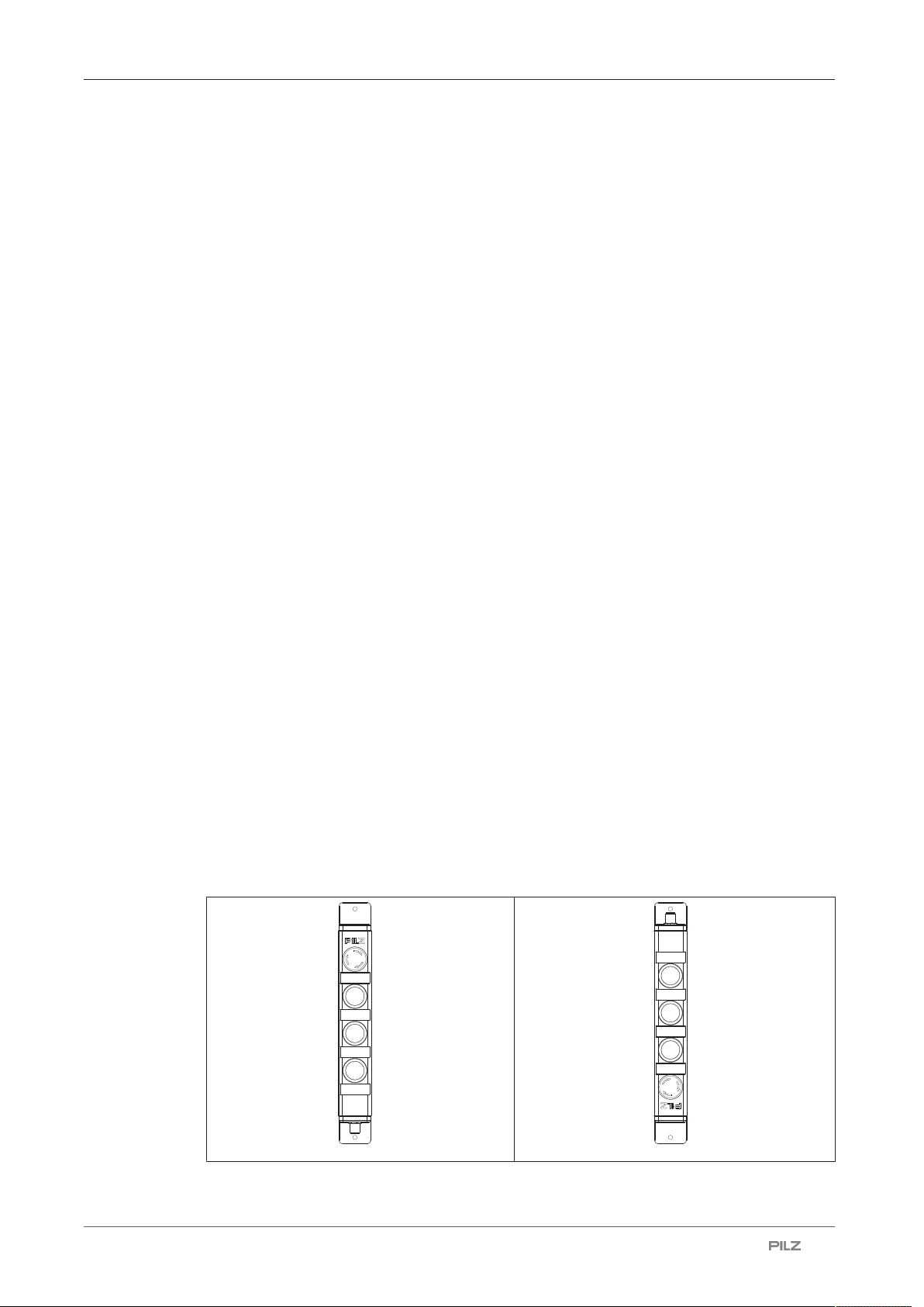
4.1 Design and device types........................................................................................................... 10
4.2 Assembly positions ................................................................................................................... 12
4.3 Block diagrams .........................................................................................................................14
5 Wiring ...................................................................................................................................... 19
5.1 Terminal assignment connectors.............................................................................................. 19
6 Installation .............................................................................................................................. 20
6.1 Installation of device ................................................................................................................. 20
6.2 Attach coloured caps ................................................................................................................ 21
6.3 Exchange of control elements .................................................................................................. 21
7 Commissioning ...................................................................................................................... 25
7.1 Connection to evaluation device............................................................................................... 25
7.2 Function test ............................................................................................................................. 25
8 Troubleshooting .................................................................................................................... 26
9 Checks and maintenance ...................................................................................................... 27
9.1 Checks...................................................................................................................................... 27
9.2 Cleaning.................................................................................................................................... 27
Operating Manual PIT gb
1004627-EN-04
| 3
Page 4

Contents
10 Dimensions ............................................................................................................................ 28
11 Technical details order no. G1000001-G1000002 ............................................................... 29
12 Technical details order no. G1000003-G1000004 ............................................................... 31
13 Technical details order no. G1000026-G1000028 ............................................................... 34
14 Technical details order no. G1000029-G1000031 ............................................................... 36
15 Technical details order no. G1000032-G1000034 ............................................................... 38
16 Safety characteristic data ..................................................................................................... 40
17 Order reference ...................................................................................................................... 41
17.1 Product ..................................................................................................................................... 41
17.2 Spare part ................................................................................................................................. 42
17.3 Accessories .............................................................................................................................. 42
18 EC declaration of conformity ................................................................................................ 44
Operating Manual PIT gb
1004627-EN-04
| 4
Page 5
Introduction
1 Introduction
1.1 Validity of documentation
This documentation is valid for the product PIT gb. It is valid until new documentation is
published.
This operating manual explains the function and operation, describes the installation and
provides guidelines on how to connect the product.
1.2 Using the documentation
This document is intended for instruction. Only install and commission the product if you
have read and understood this document. The document should be retained for future reference.
1.3 Definition of symbols
Information that is particularly important is identified as follows:
DANGER!
This warning must be heeded! It warns of a hazardous situation that poses
an immediate threat of serious injury and death and indicates preventive
measures that can be taken.
WARNING!
This warning must be heeded! It warns of a hazardous situation that could
lead to serious injury and death and indicates preventive measures that can
be taken.
CAUTION!
This refers to a hazard that can lead to a less serious or minor injury plus
material damage, and also provides information on preventive measures
that can be taken.
Operating Manual PIT gb
1004627-EN-04
NOTICE
This describes a situation in which the product or devices could be damaged and also provides information on preventive measures that can be
taken. It also highlights areas within the text that are of particular importance.
| 5
Page 6

Introduction
INFORMATION
This gives advice on applications and provides information on special features.
Operating Manual PIT gb
1004627-EN-04
| 6
Page 7

Overview
2 Overview
2.1 Unit features
} Slimline design
} Housing with 12-pin M12 male connector
} Control elements can be replaced with a new control element with the same design in the
event of repair
} Labelling option for individual marking of the control elements
} Control elements finally wired and installed
} Can be installed in 16 different directions (see Assembly positions [ 13])
} Coloured caps for marking the function of the control elements (see Order reference:
Accessories [ 41])
} Housing with E-Stop pushbutton, pushbutton and mushroom head pushbutton
The housing is available in three versions. In figures the version with E-Stop is displayed.
For further information see Design and device types [ 10].
2.2 Scope of supply
} PIT gb
} 2 washers M5
} Coloured caps (set), sorted by colour
Operating Manual PIT gb
1004627-EN-04
| 7
Page 8

Safety
3 Safety
3.1 Intended use
The unit PIT gb is intended for use in safety circuits in accordance with IEC/EN60947-5-5,
ENISO13850. Before using the device, a safety assessment of the overall system must be
performed in accordance with the Machinery Directive.
The PIT gb must be used in combination with a suitable evaluation device (see Connection
to evaluation device [ 25]).
The following is deemed improper use in particular:
} Any component, technical or electrical modification to the product
} Use of the product outside the areas described in this manual
} Use of the product outside the technical details (see chapter entitled "Technical
details [ 29]").
Foreseeable misuse
} Use of the PIT gb under corrosive environmental conditions (cooling emulsions, surface
treatment, gases, …)
Please contact Pilz.
} Use of a different object than the intended key when using the key-operated pushbutton
or the key switch.
} Blocking of the key-operated pushbutton or the key switch with a foreign body.
3.2 Safety regulations
3.2.1 Use of qualified personnel
The products may only be assembled, installed, programmed, commissioned, operated,
maintained and decommissioned by competent persons.
A competent person is a qualified and knowledgeable person who, because of their training, experience and current professional activity, has the specialist knowledge required. To
be able to inspect, assess and operate devices, systems and machines, the person has to
be informed of the state of the art and the applicable national, European and international
laws, directives and standards.
It is the company’s responsibility only to employ personnel who
} Are familiar with the basic regulations concerning health and safety / accident prevention,
} Have read and understood the information provided in the section entitled Safety
} Have a good knowledge of the generic and specialist standards applicable to the specific
application.
3.2.2 Warranty and liability
All claims to warranty and liability will be rendered invalid if
} The product was used contrary to the purpose for which it is intended,
} Damage can be attributed to not having followed the guidelines in the manual,
Operating Manual PIT gb
1004627-EN-04
| 8
Page 9
Safety
} Operating personnel are not suitably qualified,
} Any type of modification has been made (e.g. exchanging components on the PCB
boards, soldering work etc.).
3.2.3 Disposal
} When decommissioning, please comply with local regulations regarding the disposal of
electronic devices (e.g. Electrical and Electronic Equipment Act).
3.3 For your safety
WARNING!
Risk of injury due to loss of the safety function.
Manipulation of the control elements may lead to serious injury and death.
– You should prevent any possibility of the control elements being ma-
nipulated through the use of a spare control element.
– Keep the spare control element in a safe place and protect it from un-
authorised access.
– If spare control elements are used, these must be installed as de-
scribed under Exchange of control elements [ 21].
– Destroy any replaced control elements before disposal.
Operating Manual PIT gb
1004627-EN-04
| 9
Page 10
Function description
[1]
[2]
[3]
[4]
[5]
[6]
[6]
4 Function description
Depending on the version, PIT gb can provide the following pushbuttons/switches to control
the functions of the overall plant or machine:
} Emergency stop pushbutton
} Illuminated and unilluminated pushbuttons
} Key switch/key pushbutton
} Changeover switch
For each control element, PIT gb has an individual labelling option [5] and a rotatable
mounting bracket [6].
Dimensions labelling option: Width 35 mm, height 13 mm
} The control elements can be marked with coloured caps according to the function of the
control elements (see Order reference: Accessories [ 41])
4.1 Design and device types
Operating Manual PIT gb
1004627-EN-04
| 10
Page 11
Function description
PIT gb Pushbutton
[1]
LLLE Pushbutton
illuminated
Pushbutton
[2]
Pushbutton
illuminated
CLLE y Blind plug Pushbutton
illuminated
BLLE y Key
switch
KLLE Key
switch
LLLL Pushbutton
illuminated
LLUL Pushbutton
illuminated
LLTE Pushbutton
illuminated
Pushbutton
illuminated
Pushbutton
illuminated
Pushbutton
illuminated
Pushbutton
illuminated
Pushbutton
illuminated
Pushbutton
[3]
Pushbutton
illuminated
Pushbutton
illuminated
Pushbutton
illuminated
Pushbutton
illuminated
Pushbutton
illuminated
Pushbutton
(1NC) not il-
luminated,
with blanking
plate (red)
Pushbutton
(1NC) illu-
minated
Pushbutton
[4]
Emergency
stop
Emergency
stop
Emergency
stop
Emergency
stop
Pushbutton
illuminated
Pushbutton
illuminated
Emergency
stop
Signal contact
No
Yes
Yes
No
No
No
No
CSSE Blind plug Pushbutton
illuminated,
2NO
LLLP Pushbutton
illuminated
Pushbutton
illuminated
Pushbutton
illuminated,
2NO
Pushbutton
illuminated
Emergency
stop
Mushroom
head push-
button, black
CLLP y Blind plug Pushbutton
illuminated
Pushbutton
illuminated
Mushroom
head push-
button, black
WLLE Selector
switch
Pushbutton
illuminated
Pushbutton
illuminated
Emergency
stop
2x60°
DLLE y Pushbutton
unillumin-
Pushbutton
illuminated
Pushbutton
illuminated
Emergency
stop
ated
LLME Pushbutton
illuminated
Pushbutton
illuminated
Indicator
lamp
Emergency
stop
} Pushbutton
– The pushbutton is used to switch a signal and as the status display.
No
No
Yes
No
Yes
No
Operating Manual PIT gb
1004627-EN-04
– The pushbutton lights up if the corresponding input is connected.
| 11
Page 12
Function description
} Key switch
} Key-operated pushbutton
} E-STOP pushbutton
} Selector switch
– The key switch is used to switch two signals and secure this switching through re-
moval of the key.
– Three locking positions (90° to the left, start position, 90° to the right)
– The key can be removed in all three positions.
– The key-operated pushbutton is used to switch a signal and secure this switching
through removal of the key.
– The key can be removed in the start position.
The E-STOP pushbutton is used to shut down plant and machine sections in order to reduce or avert imminent or existing hazards to persons and damage to machinery or materials.
– The selector switch is used to switch a signal.
– Three locking positions (60° to the left, start position, 60° to the right)
} Pushbutton unilluminated
– The pushbutton is used to switch a signal.
} Indicator lamp
– The indicator lamp is used as a status display.
– The indicator lamp lights up if the corresponding input is connected.
} Mushroom head pushbutton black
– The mushroom head pushbutton is used to switch off plant sections.
} Pushbutton not illuminated, with protruding blanking plate red
– The pushbutton is used to switch a signal.
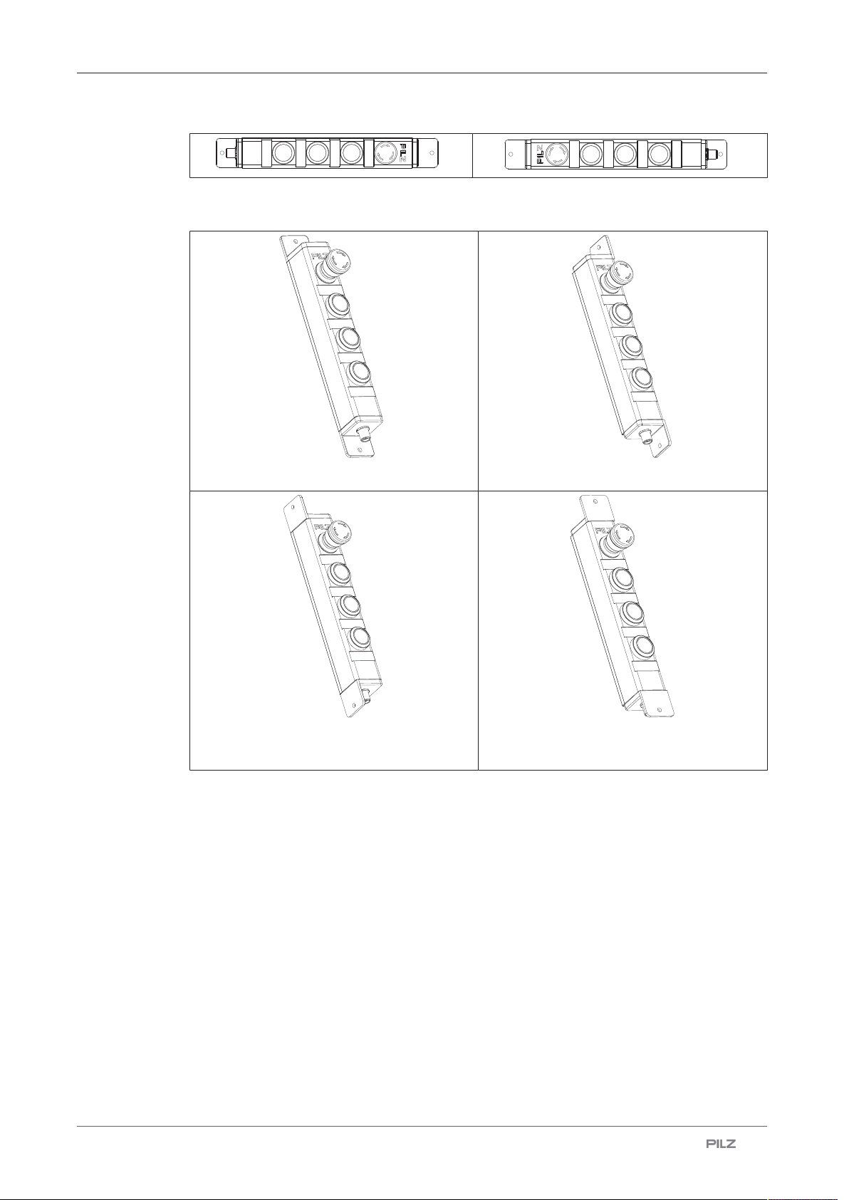
4.2 Assembly positions
Possible assembly positions for the PIT gb:
Operating Manual PIT gb
1004627-EN-04
| 12
Page 13
Function description
The mounting brackets with which the PIT gb is fastened to the mounting surface can be
turned before assembly PIT gb (see figures).
Without turning the mounting brackets Turning the mounting brackets 1x to the left
Turning the mounting brackets 1x to the
Turning the mounting bracket 2x to the right
right
Operating Manual PIT gb
1004627-EN-04
| 13
Page 14
Function description
3
5
6
10
12
7
9
8
4
12
11
H1
S1
S2
S3
S4.2
S4.1
H2
H3
2
3
5
6
10
7
9
8
12
4
S2
S3
S4.3
S4.2
S4.1
H2
H3
1
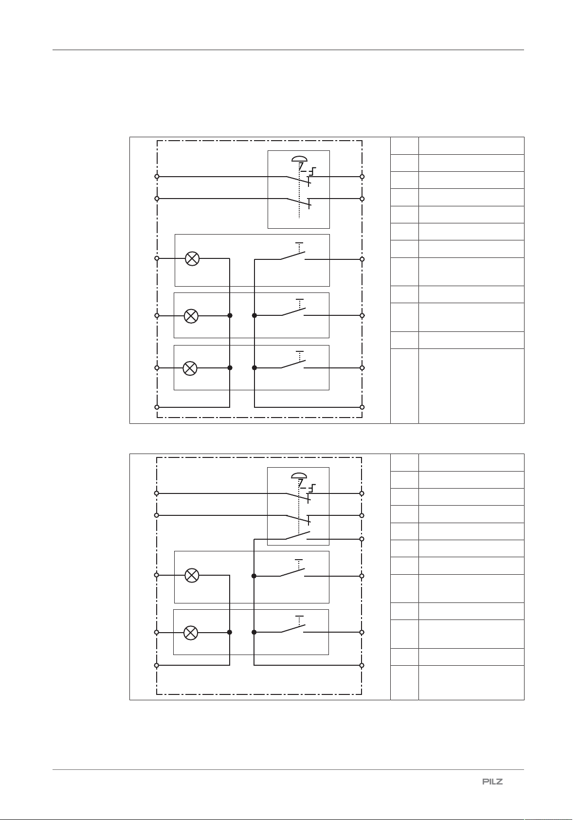
4.3 Block diagrams
PIT gb LLLE/PIT gb LLLP
1 +24 V UB
2 0 V UB
3 E-STOP channel 1
7 E-STOP channel 1
5 E-STOP channel 2
9 E-STOP channel 2
8 Pushbutton 3
10 LED pushbutton 3
(H3)
4 Pushbutton 2
6 LED pushbutton 2
(H2)
11 Pushbutton 1
12 LED pushbutton 1
(H1)
PIT gb CLLE y/PIT gb CLLP y
1 +24 V UB
2 0 V UB
3 E-STOP channel 1
7 E-STOP channel 1
5 E-STOP channel 2
9 E-STOP channel 2
8 Pushbutton 3
10 LED pushbutton 3
(H3)
4 Pushbutton 2
6 LED pushbutton 2
(H2)
11 Not connected
12 Signal contact
Operating Manual PIT gb
1004627-EN-04
| 14
Page 15

Function description
2
3
5
6
7
9
4
12
11
S1
S2
S4.2
S4.3
S4.1
H2
8
S3
10
H3
1
PIT gb BLLE y/PIT gb DLLE y
1 +24 V UB
2 0 V UB
3 E-STOP channel 1
7 E-STOP channel 1
5 E-STOP channel 2
9 E-STOP channel 2
8 Pushbutton 3
10 LED pushbutton 3
(H3)
4 Pushbutton 2
6 LED pushbutton 2
(H2)
11 Key-operated pushbut-
ton
12 Signal contact
Operating Manual PIT gb
1004627-EN-04
| 15
Page 16

Function description
3
5
6
7
9
4
12
11
S1.1
S2
S4.2
S1.2
S4.1
H2
10
H3
8
S3
12
3
6
10
12
7
8
4
12
11
H1
S1
S2
S3
H2
H3
S4
H4
PIT gb KLLE/PIT gb WLLE
1 +24 V UB +24 V UB
2 0 V UB 0 V UB
3 E-STOP channel1E-STOP channel
1
7 E-STOP channel1E-STOP channel
1
5 E-STOP channel2E-STOP channel
2
9 E-STOP channel2E-STOP channel
2
8 Pushbutton 3 Pushbutton 3
PIT gb LLLL
10 LED pushbutton
3 (H3)
LED pushbutton
3 (H3)
4 Pushbutton 2 Pushbutton 2
6 LED pushbutton
2 (H2)
11 Key switch chan-
nel 1 (key turned
90° to the right)
LED pushbutton
2 (H2)
Selector switch
channel 1 (key
turned 60° to the
left)
12 Key switch chan-
nel 2 (key turned
90° to the left)
Selector switch
channel 2 (key
turned 60° to the
right)
1 +24 V UB
2 0 V UB
3 LED pushbutton 4
(H4)
7 Pushbutton 4
5 Not connected
9 Not connected
8 Pushbutton 3
10 LED pushbutton 3
(H3)
4 Pushbutton 2
6 LED pushbutton 2
(H2)
11 Pushbutton 1
Operating Manual PIT gb
1004627-EN-04
12 LED pushbutton 1
(H1)
| 16
Page 17

Function description
3
6
12
7
8
4
12
11
H1
S1
S2
S3
H2
S4
H4
3
5
6
10
12
7
9
8
4
12
11
H1
S1
S2
S3
S4.2
S4.1
H2
H3
PIT gb LLUL
1 +24 V UB
2 0 V UB
3 LED pushbutton 4
(H4)
7 Pushbutton 4
5 Not connected
9 Not connected
8 Pushbutton 3
10 Not connected
4 Pushbutton 2
6 LED pushbutton 2
(H2)
11 Pushbutton 1
12 LED pushbutton 1
(H1)
PIT gb LLTE
1 +24 V UB
2 0 V UB
3 E-STOP channel 1
7 E-STOP channel 1
5 E-STOP channel 2
9 E-STOP channel 2
8 Pushbutton 3 (N/C)
10 LED pushbutton 3
(H3)
4 Pushbutton 2
6 LED pushbutton 2
(H2)
11 Pushbutton 1
12 LED pushbutton 1
(H1)
Operating Manual PIT gb
1004627-EN-04
| 17
Page 18

Function description
3
5
6
10
12
7
9
8
12
4
11
S2.1
S2.2
S3.1
S3.2
S4.2
S4.1
H2
H3
3
5
6
10
12
7
9
4
12
11
H1
S1
S2
S4.2
S4.1
H2
H3
PIT gb CSSE
1 +24 V UB
2 0 V UB
3 E-STOP channel 1
7 E-STOP channel 1
5 E-STOP channel 2
9 E-STOP channel 2
8 Pushbutton 3.1
10 LED pushbutton 3
(H3)
4 Pushbutton 2.1
6 LED pushbutton 2
(H2)
11 Pushbutton 2.2
12 Pushbutton 3.2
PIT gb LLME
1 +24 V UB
2 0 V UB
3 E-STOP channel 1
7 E-STOP channel 1
5 E-STOP channel 2
9 E-STOP channel 2
8 Not connected
10 LED pushbutton 3
(H3)
4 Pushbutton 2
6 LED pushbutton 2
(H2)
11 Pushbutton 1
12 LED pushbutton 1
(H1)
Operating Manual PIT gb
1004627-EN-04
| 18
Page 19

Wiring
1
2
3
4
5
6
7
8
9
10
11
12
5 Wiring
} The power supply must meet the regulations for extra low voltages with protective elec-
trical separation (SELV, PELV).
} Ensure the wiring and EMC requirements of EN 60204-1 are met.
} To connect the PIT gb to the evaluation devices, use a 12-pin cable with an A-coded M12
female connector (see Order reference: Accessories [ 42]).
Guidelines for UL certification
} Device rated Type 1, or equivalent.
} Use 75°C copper conductors 16-28 AWG only, or equivalent.
} Circuit protection shall be supplied by a fuse rated more than 4 A, or equivalent.
5.1 Terminal assignment connectors
NOTICE
The colour marking for the connection lead only applies for the cable that
Pilz supplies as an accessory
12-pin M12 male connector
PIN Wire colour
1 Brown
2 Blue
3 White
4 Green
5 Pink
6 Yellow
7 Black
8 Grey
9 Red
10 Purple
11 Grey-pink
12 Red-blue
Operating Manual PIT gb
1004627-EN-04
| 19
Page 20

Installation
5 mm
[2]
[2]
[3]
5 mm
[1]
6 Installation
6.1 Installation of device
} The mounting surface must have a max. unevenness of 0.5mm.
} The housing of the PIT gb must make contact with the mounting surface over at least
5mm on both ends (see figure).
Legend
[1] Mounting surface
[2] Mounting bracket
[3] Housing
} To fasten the PIT gb, use M5 screws and the provided washers M5.
} Torque setting: Please note the information provided under Technical details [ 29].
Procedure:
1. Provide the mounting surface with drill holes for fastening the PIT gb (see
Dimensions [ 28]).
2. Turn the housing of the PIT gb in the bracket to the correct position for installation.
3. Fasten the PIT gb to the mounting surface and tighten the screws (including washers)
with 4 Nm.
Operating Manual PIT gb
1004627-EN-04
| 20
Page 21

Installation
[1]
6.2 Attach coloured caps
Apply the coloured cap (provided) to the control element and press on the coloured cap until it noticeably engages.
Ensure that the alignment marking on the coloured cap (see figure) is aligned flush with the
PIT gb or at a 90° angle to this.
Legend
[1] Alignment marking
6.3 Exchange of control elements
Prerequisites
} The plant that is controlled by the PIT gb is not in operation and cannot be restarted
without an equivalent safety device.
} The new control element has the same design as the defective control element.
Required tool
} PIT gb fixing spanner (see Accessories [ 42]) for threaded ring of the control element
} Screwdriver for Torx Tx20
Procedure:
} Torque setting: Please note the information provided under Technical details [ 29].
1. Disconnect the connection of the PIT gb to the evaluation device.
2. Loosen the fixing screws of the PIT gb at the mounting surface.
3. Loosen the 6 fixing screws for the terminating plate of the PIT gb and remove the terminating plate.
Operating Manual PIT gb
1004627-EN-04
| 21
Page 22

Installation
[1]
Legend
[1] Terminating plate
4. Loosen the fixing screws of the printed circuit board and carefully lift off the printed cir-
Operating Manual PIT gb
1004627-EN-04
cuit board (see figures).
| 22
Page 23

Installation
5. Loosen the threaded ring of the control element that is to be exchanged and remove
the threaded ring (see figure).
1. Remove the control element on the front of the PIT gb and insert the part of the new
2. Screw the control element to the threaded ring again using 1,2 Nm (see figure) and ap-
3. Screw the printed circuit board to the fixing screws with 1,8 Nm (see figure).
Operating Manual PIT gb
1004627-EN-04
control element.
The control element has a stud on its side to secure it against twisting. The stud must
be positioned correctly when inserting the control element.
ply the printed circuit board again.
a Make sure that the strands are not damaged, crushed or twisted here.
| 23
Page 24

Installation
[1]
4. Screw the fixing screws for the PIT gbterminating plate in again and tighten the screws
with 1,8 Nm.
a Make sure that the strands are not damaged, crushed or twisted here.
Legend
5. Screw the PIT gb onto the mounting surface with the fixing screws with 4 Nm.
6. Connect the PIT gb to the evaluation device.
7. Perform a manual function test [ 25] on the unit.
8. Recommission the plant that is controlled by the PIT gb.
Apply the coloured cap (provided) to the control element and press on the coloured cap until it noticeably engages.
Ensure that the alignment marking on the coloured cap (see figure) is aligned flush with the
PIT gb or at a 90° angle to this.
Operating Manual PIT gb
1004627-EN-04
[1] Terminating plate
Only commission the plant that is controlled by the unit if the function test was successful.
| 24
Page 25

Commissioning
7 Commissioning
7.1 Connection to evaluation device
Suitable Pilz evaluation devices for the actuation of the LED and reading out all control elements include:
} PNOZmulti
} PSSuniversal PLC
Suitable Pilz evaluation devices for the evaluation of the E-STOP:
} PNOZelog
} PNOZsigma
} PNOZ X
The correct connection to the respective evaluation device is described in the operating
manual for the evaluation device. Make sure that the connection is made in accordance
with the specifications in the operating manual for the selected evaluation device.
7.2 Function test
Once the unit has been installed and aligned, final inspections must be carried out before it
can be put into service.
INFORMATION
This inspection may only be carried out by qualified personnel.
} Always test the function with a connected evaluation device.
} Check the function of the E-STOP.
} Check the function of the other control elements.
Operating Manual PIT gb
1004627-EN-04
| 25
Page 26

Troubleshooting
8 Troubleshooting
Error Cause Description/measure
LED off 0V voltage supply not
present and/or no signal
at corresponding input
No output signal with control
element operation
Control element damaged External force Exchange defective control ele-
Function of the unit impaired Connection cable dam-
24V voltage supply not
present
aged
Check the wiring of the inputs
and outputs and rectify wiring
errors
Check the wiring of the inputs
and outputs and rectify wiring
errors
ment
Check connection cable and exchange if necessary
Operating Manual PIT gb
1004627-EN-04
| 26
Page 27

Checks and maintenance
9 Checks and maintenance
It is not necessary to perform maintenance work on the product in normal operation. Please
return any faulty products to Pilz.
9.1 Checks
Monthly check
} Perform a manual function test [ 25] of the PIT gb every month.
INFORMATION
This inspection may only be carried out by qualified personnel.
Check after modifications
Check the PIT gb each time the plant/machine is modified. Changing the PIT gb or swapping PIT gb components should also be regarded as a modification.
9.2 Cleaning
Clean the unit every month with a soft cloth and a mild cleaning agent.
Operating Manual PIT gb
1004627-EN-04
| 27
Page 28

Dimensions
253,5
Ø 5,4
40
277
293
239
73,7
Ø 30
20
40
49,4
10 Dimensions
Front view Side view
Operating Manual PIT gb
1004627-EN-04
| 28
Page 29

Technical details order no. G1000001-G1000002
11 Technical details order no. G1000001-G1000002
General G1000001 G1000002
Certifications CE, EAC (Eurasian), UL/cUL CE, EAC (Eurasian), UL/cUL
Self-monitored No No
Lamp
Kind LED LED
Colour white white
Electrical data G1000001 G1000002
Supply voltage
Voltage 24 V 24 V
Kind DC DC
Voltage tolerance -20 %/+20 % -20 %/+20 %
Output of external power supply
(DC) 12 W 12 W
Duty cycle 100 % 100 %
Min. contact current 1 mA 1 mA
E-STOP G1000001 G1000002
Quantity 1 1
Number of N/C contacts 2 2
Number of signal contacts – 1
E-STOP release type Turn release Turn release
Utilisation category
In accordance with the standard EN 60947-5-1 EN 60947-5-1
DC13 at 24 V 24 V
Current 0,1 A 0,1 A
Contact material Ag Ag
Contact material signal contact – Au
Mechanical life 6050 cycles 6050 cycles
Signal output
Output voltage – 24 V
Max. current – 0,1 A
Pushbutton G1000001 G1000002
Quantity 3 2
Number of N/O contacts 3 2
Utilisation category
In accordance with the standard EN 60947-5-1 EN 60947-5-1
DC13 at 24 V 24 V
Max. current 0,1 A 0,1 A
Mechanical life 1,000,000 cycles 1,000,000 cycles
B10 1,300,000 cycles 1,300,000 cycles
Contact material Ag Ag
Environmental data G1000001 G1000002
Ambient temperature
Temperature range -20 - 60 °C -20 - 60 °C
Operating Manual PIT gb
1004627-EN-04
| 29
Page 30

Technical details order no. G1000001-G1000002
Environmental data G1000001 G1000002
Storage temperature
Temperature range -25 - 70 °C -25 - 70 °C
Climatic suitability
In accordance with the standard EN 60068-2-78 EN 60068-2-78
Humidity 93 % r. h. at 40 °C 93 % r. h. at 40 °C
Vibration
In accordance with the standard EN 60947-5-2 EN 60947-5-2
Frequency 10 - 55 Hz 10 - 55 Hz
Amplitude 1 mm 1 mm
Shock stress
In accordance with the standard EN 60947-5-2 EN 60947-5-2
Acceleration 30g 30g
Duration 11 ms 11 ms
Airgap creepage
In accordance with the standard EN 60947-1 EN 60947-1
Overvoltage category III III
Pollution degree 3 3
Protection type
Housing IP65 IP65
In accordance with UL Type 1 Type 1
Mechanical data G1000001 G1000002
Mounting position Any Any
Connection type M12, 12-pin male connector M12, 12-pin male connector
Material
Housing Zn Zn
Fixing screws torque settings 4 Nm 4 Nm
Torque setting terminating plate 1,8 Nm 1,8 Nm
Torque setting circuit board 1,8 Nm 1,8 Nm
Torque setting control element 1,2 Nm 1,2 Nm
Dimensions
Height 293 mm 293 mm
Width 40 mm 40 mm
Depth 40 mm 40 mm
Weight 800 g 800 g
Operating Manual PIT gb
1004627-EN-04
| 30
Page 31

Technical details order no. G1000003-G1000004
12 Technical details order no. G1000003-G1000004
General G1000003 G1000004
Certifications CE, EAC (Eurasian), UL/cUL CE, EAC (Eurasian), UL/cUL
Self-monitored No No
Lamp
Kind LED LED
Colour white white
Electrical data G1000003 G1000004
Supply voltage
Voltage 24 V 24 V
Kind DC DC
Voltage tolerance -20 %/+20 % -20 %/+20 %
Output of external power supply
(DC) 12 W 12 W
Duty cycle 100 % 100 %
Min. contact current 1 mA 1 mA
E-STOP G1000003 G1000004
Quantity 1 1
Number of N/C contacts 2 2
Number of signal contacts 1 –
E-STOP release type Turn release Turn release
Utilisation category
In accordance with the standard EN 60947-5-1 EN 60947-5-1
DC13 at 24 V 24 V
Current 0,1 A 0,1 A
Contact material Ag Ag
Contact material signal contact Au –
Mechanical life 6050 cycles 6050 cycles
Signal output
Output voltage 24 V –
Max. current 0,1 A –
Pushbutton G1000003 G1000004
Quantity 2 2
Number of N/O contacts 2 2
Utilisation category
In accordance with the standard EN 60947-5-1 EN 60947-5-1
DC13 at 24 V 24 V
Max. current 0,1 A 0,1 A
Mechanical life 1,000,000 cycles 1,000,000 cycles
B10 1,300,000 cycles 1,300,000 cycles
Contact material Ag Ag
Key-operated pushbutton G1000003 G1000004
Quantity 1 –
Number of N/O contacts 1 –
Operating Manual PIT gb
1004627-EN-04
| 31
Page 32

Technical details order no. G1000003-G1000004
Key-operated pushbutton G1000003 G1000004
Utilisation category
In accordance with the standard EN 60947-5-1 –
DC13 at 24 V –
Max. current 0,1 A –
Mechanical life 30,000 cycles –
Service life mechanical, key not removed 300,000 cycles –
B10 40,000 cycles –
B10 without key removal 400,000 cycles –
Contact material Ag
–
Key switch G1000003 G1000004
Quantity – 1
Number of N/O contacts – 2
Utilisation category
In accordance with the standard – EN 60947-5-1
DC13 at – 24 V
Max. current – 0,1 A
Mechanical life – 30,000 cycles
Service life mechanical, key not removed – 300,000 cycles
B10 – 40,000 cycles
B10 without key removal – 65,000 cycles
Contact material
–
Ag
Environmental data G1000003 G1000004
Ambient temperature
Temperature range -20 - 60 °C -20 - 60 °C
Storage temperature
Temperature range -25 - 70 °C -25 - 70 °C
Climatic suitability
In accordance with the standard EN 60068-2-78 EN 60068-2-78
Humidity 93 % r. h. at 40 °C 93 % r. h. at 40 °C
Vibration
In accordance with the standard EN 60947-5-2 EN 60947-5-2
Frequency 10 - 55 Hz 10 - 55 Hz
Amplitude 1 mm 1 mm
Shock stress
In accordance with the standard EN 60947-5-2 EN 60947-5-2
Acceleration 30g 30g
Duration 11 ms 11 ms
Airgap creepage
In accordance with the standard EN 60947-1 EN 60947-1
Overvoltage category III III
Pollution degree 3 3
Operating Manual PIT gb
1004627-EN-04
| 32
Page 33

Technical details order no. G1000003-G1000004
Environmental data G1000003 G1000004
Protection type
Housing IP65 IP65
In accordance with UL Type 1 Type 1
Mechanical data G1000003 G1000004
Mounting position Any Any
Connection type M12, 12-pin male connector M12, 12-pin male connector
Material
Housing Zn Zn
Fixing screws torque settings 4 Nm 4 Nm
Torque setting terminating plate 1,8 Nm 1,8 Nm
Torque setting circuit board 1,8 Nm 1,8 Nm
Torque setting control element 1,2 Nm 1,2 Nm
Dimensions
Height 293 mm 293 mm
Width 40 mm 40 mm
Depth 40 mm 40 mm
Weight 800 g 800 g
Operating Manual PIT gb
1004627-EN-04
| 33
Page 34

Technical details order no. G1000026-G1000028
13 Technical details order no. G1000026-G1000028
General G1000026 G1000027 G1000028
Certifications CE, EAC (Eurasian), UL/
cUL
Self-monitored No No No
Lamp
Kind LED LED –
Electrical data G1000026 G1000027 G1000028
Supply voltage
Voltage 24 V 24 V 24 V
Kind DC DC DC
Duty cycle 100 % 100 % 100 %
E-STOP G1000026 G1000027 G1000028
Quantity – – 1
Number of N/C contacts – – 2
E-STOP release type – – Turn release
Utilisation category
In accordance with the
standard – – EN 60947-5-1
DC13 at – – 24 V
Current – – 0,1 A
Contact material – – Ag
Mechanical life
Pushbutton G1000026 G1000027 G1000028
Quantity 4 3 3
Number of N/C contacts – – 1
Number of N/O contacts 4 3 2
Utilisation category
In accordance with the
standard EN 60947-5-1 EN 60947-5-1 EN 60947-5-1
DC13 at 24 V 24 V 24 V
Max. current 0,1 A 0,1 A 0,1 A
Mechanical life 1,000,000 cycles 1,000,000 cycles 1,000,000 cycles
Contact material Ag Ag Ag
Pushbutton with blanking plate (red)
Quantity – 1 –
Utilisation category
In accordance with the
standard – EN 60947-5-1 –
DC13 at – 24 V –
Max. current – 0,1 A –
Mechanical life – 1,000,000 cycles –
B10 – 1,300,000 cycles –
– –
G1000026 G1000027 G1000028
CE, EAC (Eurasian), UL/
cUL
CE, EAC (Eurasian), UL/
cUL
6050 cycles
Operating Manual PIT gb
1004627-EN-04
| 34
Page 35

Technical details order no. G1000026-G1000028
Pushbutton with blank-
G1000026 G1000027 G1000028
ing plate (red)
Contact material
–
Ag
–
Environmental data G1000026 G1000027 G1000028
Ambient temperature
Temperature range -20 - 60 °C -20 - 60 °C -20 - 60 °C
Storage temperature
Temperature range -25 - 70 °C -25 - 70 °C -25 - 70 °C
Vibration
Frequency 10 - 55 Hz 10 - 55 Hz 10 - 55 Hz
Amplitude 0,35 mm 0,35 mm 0,35 mm
Protection type
Housing IP65 IP65 IP65
In accordance with UL Type 1 Type 1 Type 1
Mechanical data G1000026 G1000027 G1000028
Mounting position Any Any Any
Connection type M12, 12-pin male con-
nector
M12, 12-pin male connector
M12, 12-pin male connector
Material
Housing Zn Zn Zn
Fixing screws torque settings 4 Nm 4 Nm 4 Nm
Torque setting terminating
plate 1,8 Nm 1,8 Nm 1,8 Nm
Torque setting circuit
board 1,8 Nm 1,8 Nm 1,8 Nm
Torque setting control element 1,2 Nm 1,2 Nm 1,2 Nm
Dimensions
Height 293 mm 293 mm 293 mm
Width 40 mm 40 mm 40 mm
Depth 40 mm 40 mm 40 mm
Weight 800 g 800 g 800 g
Operating Manual PIT gb
1004627-EN-04
| 35
Page 36

Technical details order no. G1000029-G1000031
14 Technical details order no. G1000029-G1000031
General G1000029 G1000030 G1000031
Certifications CE, EAC (Eurasian), UL/
cUL
Self-monitored No No No
Electrical data G1000029 G1000030 G1000031
Supply voltage
Voltage 24 V 24 V 24 V
Kind DC DC DC
Duty cycle 100 % 100 % 100 %
E-STOP G1000029 G1000030 G1000031
Quantity 1 – –
Number of N/C contacts 2 – –
E-STOP release type Turn release – –
Utilisation category
In accordance with the
standard EN 60947-5-1 – –
DC13 at 24 V – –
Current 0,1 A – –
Contact material Ag – –
Mechanical life 6050 cycles
Pushbutton G1000029 G1000030 G1000031
Quantity 2 3 2
Number of N/O contacts 4 3 2
Utilisation category
In accordance with the
standard EN 60947-5-1 EN 60947-5-1 EN 60947-5-1
DC13 at 24 V 24 V 24 V
Max. current 0,1 A 0,1 A 0,1 A
Mechanical life 1,000,000 cycles 1,000,000 cycles 1,000,000 cycles
Contact material Ag Ag Ag
Mushroom head pushbutton
Quantity – 1 1
Number of N/C contacts – 2 2
Release type – Turn release Turn release
Utilisation category
In accordance with the
standard – EN 60947-5-1 EN 60947-5-1
DC13 at – 24 V 24 V
Max. current – 0,1 A 0,1 A
Mechanical life – 50,000 cycles 50,000 cycles
Contact material
G1000029 G1000030 G1000031
–
CE, EAC (Eurasian), UL/
cUL
– –
Ag Ag
CE, EAC (Eurasian), UL/
cUL
Operating Manual PIT gb
1004627-EN-04
| 36
Page 37

Technical details order no. G1000029-G1000031
Environmental data G1000029 G1000030 G1000031
Ambient temperature
Temperature range -20 - 60 °C -20 - 60 °C -20 - 60 °C
Storage temperature
Temperature range -25 - 70 °C -25 - 70 °C -25 - 70 °C
Vibration
Frequency 10 - 55 Hz 10 - 55 Hz 10 - 55 Hz
Amplitude 0,35 mm 0,35 mm 0,35 mm
Protection type
Housing IP65 IP65 IP65
In accordance with UL Type 1 Type 1 Type 1
Mechanical data G1000029 G1000030 G1000031
Mounting position Any Any Any
Connection type M12, 12-pin male con-
nector
M12, 12-pin male connector
M12, 12-pin male connector
Material
Housing Zn Zn Zn
Fixing screws torque settings 4 Nm 4 Nm 4 Nm
Torque setting terminating
plate 1,8 Nm 1,8 Nm 1,8 Nm
Torque setting circuit
board 1,8 Nm 1,8 Nm 1,8 Nm
Torque setting control element 1,2 Nm 1,2 Nm 1,2 Nm
Dimensions
Height 293 mm 293 mm 293 mm
Width 40 mm 40 mm 40 mm
Depth 40 mm 40 mm 40 mm
Weight 800 g 800 g 800 g
Operating Manual PIT gb
1004627-EN-04
| 37
Page 38

Technical details order no. G1000032-G1000034
15 Technical details order no. G1000032-G1000034
General G1000032 G1000033 G1000034
Certifications CE, EAC (Eurasian), UL/
cUL
Self-monitored No No No
Electrical data G1000032 G1000033 G1000034
Supply voltage
Voltage 24 V 24 V 24 V
Kind DC DC DC
Duty cycle 100 % 100 % 100 %
E-STOP G1000032 G1000033 G1000034
Quantity 1 1 1
Number of N/C contacts 2 2 2
E-STOP release type Turn release Turn release Turn release
Utilisation category
In accordance with the
standard EN 60947-5-1 EN 60947-5-1 EN 60947-5-1
DC13 at 24 V 24 V 24 V
Current 0,1 A 0,1 A 0,1 A
Contact material Ag Ag Ag
Mechanical life 6050 cycles 6050 cycles 6050 cycles
Pushbutton G1000032 G1000033 G1000034
Quantity 2 3 2
Number of N/O contacts 2 3 2
Utilisation category
In accordance with the
standard EN 60947-5-1 EN 60947-5-1 EN 60947-5-1
DC13 at 24 V 24 V 24 V
Max. current 0,1 A 0,1 A 0,1 A
Mechanical life 1,000,000 cycles 1,000,000 cycles 1,000,000 cycles
Contact material Ag Ag Ag
Selector switch G1000032 G1000033 G1000034
Quantity 1 – –
Number of N/O contacts 2 – –
Utilisation category
In accordance with the
standard EN 60947-5-1 – –
DC13 at 24 V – –
Max. current 0,1 A – –
Mechanical life – – –
B10 – – –
Contact material Ag
CE, EAC (Eurasian), UL/
cUL
– –
CE, EAC (Eurasian), UL/
cUL
Operating Manual PIT gb
1004627-EN-04
| 38
Page 39

Technical details order no. G1000032-G1000034
Environmental data G1000032 G1000033 G1000034
Ambient temperature
Temperature range -20 - 60 °C -20 - 60 °C -20 - 60 °C
Storage temperature
Temperature range -25 - 70 °C -25 - 70 °C -25 - 70 °C
Vibration
Frequency 10 - 55 Hz 10 - 55 Hz 10 - 55 Hz
Amplitude 0,35 mm 0,35 mm 0,35 mm
Protection type
Housing IP65 IP65 IP65
In accordance with UL Type 1 Type 1 Type 1
Mechanical data G1000032 G1000033 G1000034
Mounting position Any Any Any
Connection type M12, 12-pin male con-
nector
M12, 12-pin male connector
M12, 12-pin male connector
Material
Housing Zn Zn Zn
Fixing screws torque settings 4 Nm 4 Nm 4 Nm
Torque setting terminating
plate 1,8 Nm 1,8 Nm 1,8 Nm
Torque setting circuit
board 1,8 Nm 1,8 Nm 1,8 Nm
Torque setting control element 1,2 Nm 1,2 Nm 1,2 Nm
Dimensions
Height 293 mm 293 mm 293 mm
Width 40 mm 40 mm 40 mm
Depth 40 mm 40 mm 40 mm
Weight 800 g 800 g 800 g
Operating Manual PIT gb
1004627-EN-04
| 39
Page 40

Safety characteristic data
16 Safety characteristic data
NOTICE
You must comply with the safety characteristic data in order to achieve the
required safety level for your plant/machine.
Safety characteristic data
B10d in accordance with EN ISO 13849-1:2015
and EN 62061
130.000
Operating Manual PIT gb
1004627-EN-04
| 40
Page 41

Order reference
17 Order reference
17.1 Product
Product type Features Order no.
PIT gb LLLE Housing with three illuminated push-
buttons, one E-STOP and coloured
caps
PIT gb CLLE y Housing with blind plug, two illumin-
ated pushbuttons, one E-STOP with
signal contact and coloured caps
PIT gb BLLE y Housing with key-operated pushbut-
ton, two illuminated pushbuttons, one
E-STOP with signal contact and coloured caps
PIT gb KLLE Housing with key switch, two illumin-
ated pushbuttons, one E-STOP and
coloured caps
PIT gb LLLL Housing with four illuminated push-
buttons and coloured caps
PIT gb LLUL Housing with three illuminated push-
buttons, one unilluminated pushbutton with protruding blanking plate
(red) and coloured caps
PIT gb LLTE Housing with three illuminated push-
buttons, one E-STOP and coloured
caps
M12, 12-pin male connector G1 000 001
M12, 12-pin male connector G1 000 002
M12, 12-pin male connector G1 000 003
M12, 12-pin male connector G1 000 004
M12, 12-pin male connector G1 000 026
M12, 12-pin male connector G1 000 027
M12, 12-pin male connector G1 000 028
PIT gb CSSE Housing with blind plug, two illumin-
ated pushbuttons, one E-STOP and
coloured caps
PIT gb LLLP Housing with three illuminated push-
buttons, one E-STOP and coloured
caps
PIT gb CLLP y Housing with blind plug, two illumin-
ated pushbuttons, one mushroom
head pushbutton with signal contact
and coloured caps
PIT gb WLLE Housing with selector switch, two illu-
minated pushbuttons, one E-STOP
and coloured caps
PIT gb DLLE y Housing with unilluminated pushbut-
ton, two illuminated pushbuttons, one
E-STOP with signal contact and coloured caps
PIT gb LLME Housing with three illuminated push-
buttons, one indicator lamp, one ESTOP and coloured caps
M12, 12-pin male connector G1 000 029
M12, 12-pin male connector G1 000 030
M12, 12-pin male connector G1 000 031
M12, 12-pin male connector G1 000 032
M12, 12-pin male connector G1 000 033
M12, 12-pin male connector G1 000 034
Operating Manual PIT gb
1004627-EN-04
| 41
Page 42

Order reference
17.2 Spare part
Product type Features Order no.
PIT gb es1 E-STOP without signal contact G1 000 005
PIT gb es2 E-STOP with signal contact G1 000 011
PIT gb push button Pushbutton, illuminated G1 000 006
PIT gb key button Key-operated pushbutton G1 000 007
PIT gb key switch Key switch with 2 locked positions G1 000 008
PIT gb color covers Colour covers for the illuminated pushbuttons (set) G1 000 009
PIT gb blind cover Blind plug G1 000 010
PIT gb push button
red
PIT gb push button
black
PIT gb push button
black plus 1
PIT gb selector
switch
PIT gb signal indicator
PIT gb spare part
key
Illuminated pushbutton, protruding blanking plate, round G1 000 035
Mushroom head pushbutton, black G1 000 036
Mushroom head pushbutton with signal contact, black G1 000 037
Selector switch, three positions, resting G1 000 038
Signal indicator with exchangeable blanking plate, white G1 000 039
Spare key for current key-operated pushbutton/key switch G1 000 040
17.3 Accessories
Product type Features Order no.
PIT gb fixing spanner
PIT gb color cover
wh s1
Fixing spanner for threaded rings G1 000 012
Colour covers for the illuminated pushbuttons, white, IEC symbol
Start
G1 000 013
PIT gb color cover
wh s2
PIT gb color cover
wh s3
PIT gb color cover
wh s4
PIT gb color cover
bl s5
PIT gb color cover
bl s6
PIT gb color cover
bl s4
Operating Manual PIT gb
1004627-EN-04
Colour covers for the illuminated pushbuttons, white, IEC symbol
ON
Colour covers for the illuminated pushbuttons, white, IEC symbol
Unlocking
Colour covers for the illuminated pushbuttons, white, IEC symbol
Locking
Colour covers for the illuminated pushbuttons, blue, IEC symbol Request
Colour covers for the illuminated pushbuttons, blue, IEC symbol Reset
Colour covers for the illuminated pushbuttons, blue, IEC symbol
Locking
G1 000 014
G1 000 015
G1 000 016
G1 000 017
G1 000 018
G1 000 019
| 42
Page 43

Order reference
Product type Features Connector X1 Connector X2 Connector X3 Order no.
PSEN cable
M12-12sf 2m
PSEN cable
M12-12sf 3m
PSEN cable
M12-12sf 5m
PSEN cable
M12-12sf 10m
PSEN cable
M12-12sf 20m
PSEN cable
M12-12sf 30m
PSEN cable
M12-12sf 50m
2 m M12, 12-pin fe-
male connector, straight
3 m M12, 12-pin fe-
male connector, straight
5 m M12, 12-pin fe-
male connector, straight
10 m M12, 12-pin fe-
male connector, straight
20 m M12, 12-pin fe-
male connector, straight
30 m M12, 12-pin fe-
male connector, straight
50 m M12, 12-pin fe-
male connector, straight
570 350
570 351
570 352
570 353
570 354
570 355
570 356
Operating Manual PIT gb
1004627-EN-04
| 43
Page 44

EC declaration of conformity
18 EC declaration of conformity
This product/these products meet the requirements of the directive 2006/42/EC for machinery of the European Parliament and of the Council. The complete EC Declaration of
Conformity is available on the Internet at www.pilz.com/downloads.
Authorised representative: Norbert Fröhlich, Pilz GmbH & Co. KG, Felix-Wankel-Str. 2,
73760 Ostfildern, Germany
Operating Manual PIT gb
1004627-EN-04
| 44
 Loading...