

Page 1

1002172-3FR-06
4 D Betriebsanleitung
4 GB Operating instructions
4 F Manuel d'utilisation
PIT en1.0/PIT en1.1
1002172-3FR-06PIT en1.0/PIT en1.1
Zustimmtaster PIT en1.0/PIT en1.1
1221882507
Der Zustimmtaster PIT en1.0p/PIT en1.0a/
PIT en1.1a ist ein handbetätigter Befehlsgeber,
der bei automatisierten Fertigungseinrichtungen im manuellen Betrieb als Zustimmeinrichtung eingesetzt werden kann. Autorisiertes
Personal kann bei geöffneten beweglich trennenden Schutzeinrichtungen den Gefahrenbereich betreten, um Arbeitsabläufe zu
beobachten oder Einricht- bzw. Wartungsarbeiten durchzuführen.
Jede Person, die den Gefahrenbereich betritt,
muss mit einem Zustimmtaster ausgestattet
sein.
Es dürfen ausschließlich Auswertegeräte mit
Querschlussüberwachung eingesetzt werden.
Wir empfehlen als Auswertegeräte die in Kapitel "Anschluss an Auswertegerät" beschriebenen Geräte.
Der Zustimmtaster darf nicht allein eingesetzt
werden, um gefahrbringende Zustände einzuschalten.
Der Zustimmtaster darf nicht als Ersatz für andere Sicherheitsmaßnahmen eingesetzt werden.
Enabling switch PIT en1.0/PIT en1.1
The enabling switch PIT en1.0p/PIT en1.0a/
PIT en1.1a is a manually operated control device, which can be used as an enabling device
when automated production equipment is used
in manual mode. Authorised personnel can access the danger zone while movable guards are
open, to monitor workflows or carry out setup
or maintenance work.
Each person accessing the danger zone must
be equipped with an enabling switch.
Only evaluation devices that monitor for shorts
across contacts may be used. As evaluation
devices we recommend the devices described
under "Connection to evaluation device".
The enabling switch may not be used on its
own to switch on a potentially hazardous condition.
The enabling switch may not be used in place
of other safety measures.
Poignée d'assentiment PIT en1.0/
PIT en1.1
La poignée d'assentiment PIT en1.0p/
PIT en1.0a/PIT en1.1a est un organe de commande manuel qui peut être utilisé comme dispositif de validation en fonctionnement manuel
dans des équipements de fabrication automatisés. Même lorsque les protecteurs mobiles
sont ouverts, le personnel autorisé peut pénétrer dans la zone dangereuse pour surveiller les
procédures ou effectuer des travaux de réglage
ou de maintenance.
Toute personne qui pénètre dans la zone dangereuse doit être équipée d'une poignée d'assentiment.
Seules des unités de contrôle avec surveillance
des courts-circuits peuvent être utilisées. Nous
recommandons d'utiliser les unités de contrôle
décrites dans le chapitre « Raccordement à
l'unité de contrôle ».
La poignée d'assentiment ne doit pas être utilisée seule pour activer des états dangereux.
La poignée d'assentiment ne doit pas être utilisée en remplacement d'autres mesures de sécurité.
Zu Ihrer Sicherheit
547263243
Installieren und nehmen Sie das Gerät nur
dann in Betrieb, wenn Sie diese Betriebsanleitung gelesen und verstanden haben und
Sie mit den geltenden Vorschriften über Arbeitssicherheit und Unfallverhütung vertraut
sind.
Beachten Sie die VDE- sowie die örtlichen
Vorschriften, insbesondere hinsichtlich
Schutzmaßnahmen
Durch Öffnen des Gehäuses oder eigen-
mächtige Umbauten erlischt jegliche Gewährleistung.
1227773451
Prüfen Sie die Funktion des Tasters vor der
ersten Inbetriebnahme und führen Sie regelmäßige Prüfungen (mind. jährlich) durch.
Gerätemerkmale
1221884811
Der Zustimmtaster ist in einem Kunststoffgehäuse untergebracht.
Merkmale:
3-stufiger Taster (Aus - Ein - Aus)
1 Meldekontakt
Anschluss PIT en1.0p: Kabel (5 m) mit 5-po-
ligem M12-Winkelstecker
Anschluss PIT en1.0a: 6-adriges Kabel (5 m)
mit offenem Ende
Anschluss PIT en1.1a: 6-adriges Spiralkabel
(5 m) mit offenem Ende
integrierter Haftmagnet zum Befestigen des
Zustimmtasters z. B. an der Maschine
For your safety
Only install and commission the unit if you
have read and understood these operating
instructions and are familiar with the applicable regulations for health and safety at work
and accident prevention.
Ensure VDE and local regulations are met,
especially those relating to safety.
Any guarantee is rendered invalid if the hous-
ing is opened or unauthorised modifications
are carried out.
Check the function of the pushbutton before
commissioning for the first time and then at
regular intervals (at least annually).
Unit features
The enabling switch is enclosed in plastic housing.
Features:
3-stage switch (off - on - off)
1 signal contact
Connection PIT en1.0p: Cable (5 m) with 5-
pin M12 angled connector
Connection PIT en1.0a: 6-core open-ended
cable (5 m)
Connection PIT en1.1a: 6-core open-ended
coiled cable (5 m)
Integrated magnetic clamp to attach the en-
abling switch to the machine, for example
Pour votre sécurité
Vous n'installerez l'appareil et ne le mettrez
en service qu'après avoir lu et compris le
présent manuel d'utilisation et vous être familiarisé avec les prescriptions en vigueur
sur la sécurité du travail et la prévention des
accidents.
Respectez les normes locales ou VDE, particulièrement en ce qui concerne la sécurité.
L'ouverture de l'appareil ou sa modification
annule automatiquement la garantie.
Vérifiez le fonctionnement du bouton-pous-
soir avant sa première mise en service et effectuez des contrôles réguliers (min. 1 fois
par an).
Caractéristiques de l'appareil
La poignée d'assentiment est logée dans un
boîtier en matière plastique.
Particularités :
Poignée à 3 positions (arrêt - marche - arrêt)
1 contact d'information
Raccordement de PIT en1.0p : câble (5 m)
avec connecteur coudé M12 à 5 broches
Raccordement de PIT en1.0a : câble à 6
brins (5 m) avec extrémité ouverte
Raccordement de PIT en1.1a : câble spiralé
à 6 brins (5 m) avec extrémité ouverte
Aimant adhérent intégré pour la fixation de la
poignée d'assentiment, par exemple, sur la
machine
- 1 -
Page 2
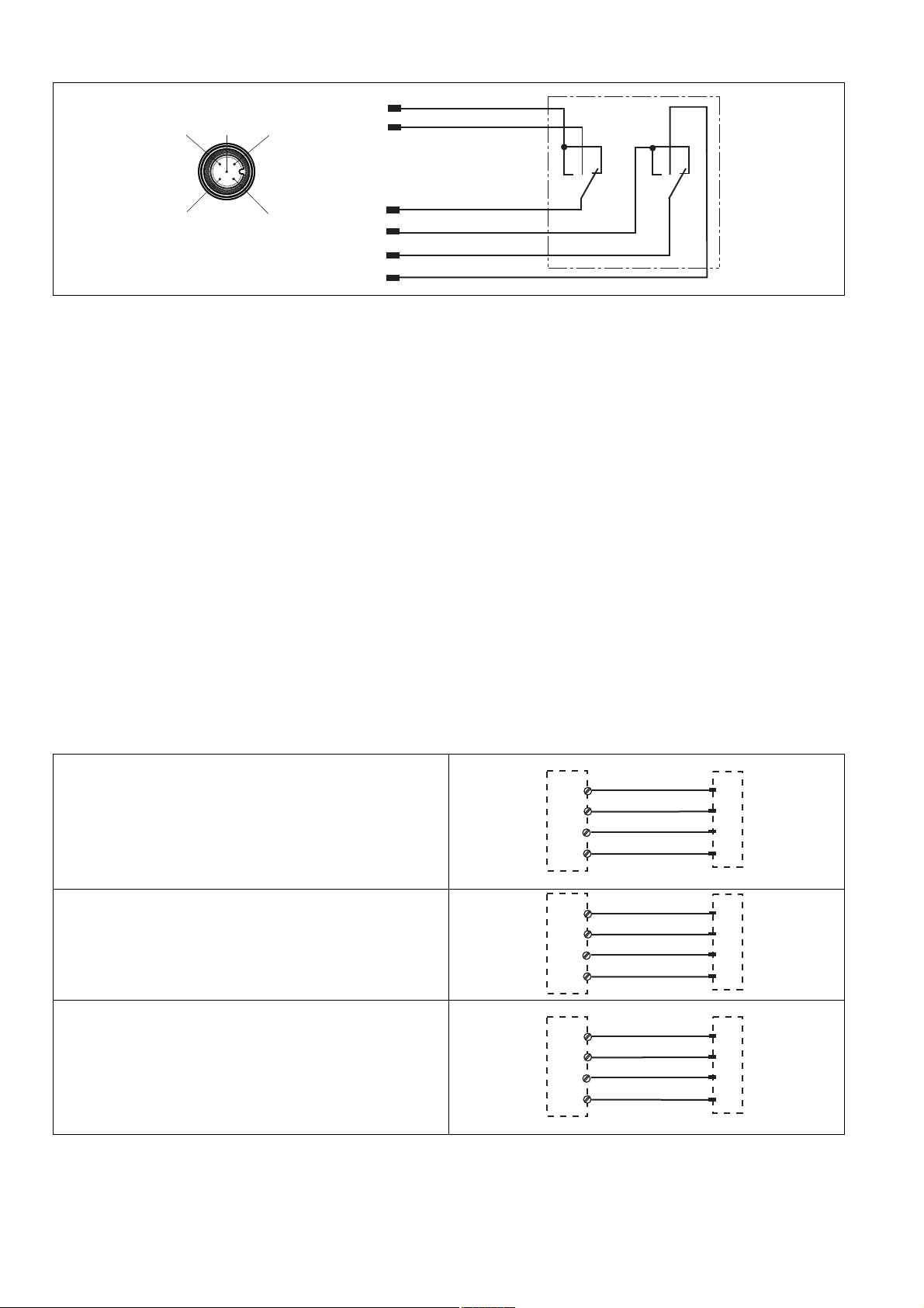
Blockschaltbild/Klemmenbelegung Block diagram/terminal configuration Schéma de principe / affectation des
1
2
3
4
5
grün/green/vert
weiß/white/blanc
gelb/yellow/jaune
braun/brown/marron
grau/grey/gris
2
3
4
1
5
rosa/pink/rose
n. c.
PNOZ e1p
PNOZ e1.1p
PNOZ e1vp
PNOZ e6.1p
PNOZ e6vp
PNOZ s3
PNOZ s4
PNOZ s5
PNOZ X2C
PNOZ X2
PNOZ X2.7P
PNOZ X2.8P
PNOZ X2.9P
S11
S12
S21
S22
weiß/white/blanc
gelb/yellow/jaune
grün/green/vert
braun/brown/marron
3
4
1
2
PNOZ e5.11p
A1
S32
A1
S24
weiß/white/blanc
gelb/yellow/jaune
grün/green/vert
braun/brown/marron
3
4
1
2
PNOZ X3.1
PNOZ X3P
PNOZ X3
PNOZ X3.10P
PNOZ XV2
PNOZ XV2P
PNOZ XV3
PNOZ XV3P
S31
S32
S21
S22
weiß/white/blanc
gelb/yellow/jaune
grün/green/vert
braun/brown/marron
3
4
1
2
bornes
Funktionsbeschreibung
1221887115
Der Zustimmtaster ist 3-stufig ausgeführt:
nicht gedrückt: kein Zustimmsignal (Aus)
gedrückt bis Mittelstellung: Zustimmsignal
aktiviert (Ein, Zustimmfunktion)
gedrückt bis Endanschlag: kein Zustimmsi-
gnal (Aus, Panikfunktion)
Dadurch ist gewährleistet, dass sowohl bei
Loslassen als auch bei Durchdrücken des Tasters das Zustimmsignal unterbrochen wird.
Wird der Zustimmtaster bis Endanschlag gedrückt und dann wieder losgelassen, bleibt er
auch während des Wechsels ausgeschaltet.
Verdrahtung
1221897611
Beachten Sie beim Verdrahten:
Schützen Sie die Leitungen vor Beschädi-
gung z. B. durch einen Schutzschlauch.
Verwenden Sie geschirmte Leitungen und
verbinden Sie den Schirm mit dem Schutzlei-
tersystem der Maschine/Anlage.
Function description
The switch is a 3-stage enabling switch:
Not operated: no enabling signal (off)
Operated as far as middle setting: enabling
signal activated (on, enabling function)
Operated as far as end stop: no enabling sig-
nal (off, panic function)
This guarantees that the enabling signal is interrupted not only when the switch is released
but also when it is fully operated.
If the enabling switch is fully operated as far as
the end stop and then released, it will remain
switched off during the changeover.
Wiring
When wiring, please note:
Protect the cables from damage, by using a
protective tube for example.
Use shielded cables and connect the shield
to the plant/machine's protective earth sys-
tem.
Description du fonctionnement
La poignée d'assentiment possède 3 positions
:
non appuyée : pas de signal d'assentiment
(éteint)
appuyée jusqu'en position centrale : signal
d'assentiment activé (allumé, fonction de validation)
appuyée jusqu'à la butée finale : pas de si-
gnal d'assentiment (éteint, fonction de pani-
que)
Cela garantit que le signal d'assentiment est interrompu à la fois en cas de relâchement et en
cas d'appui continu sur la poignée.
Si la poignée d'assentiment est appuyée jusqu'à la butée finale puis relâchée, elle reste à
l'arrêt même durant le changement.
Câblage
Lors du câblage, tenez compte des éléments
suivants :
Protégez les câbles contre les dommages,
par exemple, à l'aide d'un tube de protec-
tion.
Utilisez des câbles blindés et reliez le blinda-
ge au conducteur de protection (PE) de la
machine / installation.
Anschluss an Auswertegerät Connection to evaluation device Raccordement à l'unité de contrôle
Anschluss an PNOZ X, PNOZsigma und
PNOZelog
Connection to PNOZ X, PNOZsigma,
PNOZelog
Raccordement aux PNOZ X, PNOZsigma,
PNOZelog
Anschluss an PDP67 F 8DI ION
1485886731
Der Anschluss erfolgt über den Adapter
PSEN mag ad (s. Bedienungsanleitung PSEN
adapt PSS67/PDP67 4p).
Connection to PDP67 F 8DI ION
The connection is made via the adapter
PSEN mag ad (see operating manual PSEN
adapt PSS67/PDP67 4p).
- 2 -
Raccordement au PDP67 F 8DI ION
Le raccordement a lieu par l'adaptateur
PSEN mag ad (voir le manuel d'utilisation PSEN
adapt PSS67/PDP67 4p).
Page 3

Anschluss an PNOZmulti Connection to PNOZmulti Raccordement au PNOZmulti
Schutztür/safety gate/protecteur mobile
Schaltertyp 3/switch type 3/type du capteur 3
I0, I1: Eingänge/inputs/entrées
T0, T1: Testtaktausgänge/test pulse outputs/sorties
impulsionelles
T1
I1
T0
I0
weiß/white/blanc
gelb/yellow/jaune
grün/green/vert
braun/brown/marron
3
4
1
2
Schutztür/safety gate/protecteur mobile
Schaltertyp 3/switch type 3/type du capteur 3
I0, I1: Eingänge/inputs/entrées
O16, O17: Testtaktausgänge/test pulse outputs/sorties
impulsionelles
O17
I1
O16
I0
weiß/white/blanc
gelb/yellow/jaune
grün/green/vert
braun/brown/marron
3
4
1
2
Anschluss an PSS mit und ohne
SafetyBUS p
1268026379
Wir empfehlen, beim Anschluss an eine PSS
den Standardfunktionsbaustein SB064 oder
SB066 zu verwenden.
Connection to PSS with or without
SafetyBUS p
We recommend that you use the standard
function block SB064 or SB066 for connecting
to a PSS.
Raccordement au PSS avec ou sans
SafetyBUS p
Pour le raccordement à un PSS, nous recommandons d'utiliser le bloc fonction standard
SB064 ou SB066.
Abmessungen Dimensions Dimensions
Zustimmtaster Enabling switch Poignée d'assentiment
Halter Bracket Support
Technische Daten Technical details Caractéristiques techniques
Elektrische Daten Electrical data Données électriques
Gebrauchskategorie nach
EN 60947-5-1
Utilisation category in accordance
with EN 60947-5-1
AC15 bei 125 V AC15 bei 125 V AC15 bei 125 V 0,3 A
DC13 bei 30 V (6 Schaltspiele/min) DC13 bei 30 V (6 cycles/min) DC13 bei 30 V (6 manœuvres/min) 0,7 A
DC12 bei 30 V DC12 bei 30 V DC12 bei 30 V 1,0 A
Umweltdaten Environmental data Données sur l'environnement
Bemessungsisolationsspannung Rated insulation voltage Tension assignée d'isolement 125 V
Umgebungstemperatur Ambient temperature Température d'utilisation 0 - 50 °C
Lagertemperatur Storage temperature Température de stockage -20 - 50 °C
Schutzart Protection type Indice de protection IP65
Mechanische Daten Mechanical data Données mécaniques
Gehäusematerial Housing material Matériau du boîtier
Gehäuse Housing Boîtier PP
Catégorie d'utilisation selon
EN 60947-5-1
- 3 -
Page 4

Mechanische Daten Mechanical data Données mécaniques
Abmessungen Dimensions Dimensions
Höhe Height Hauteur 125,0 mm
Breite Width Largeur 45,0 mm
Tiefe Depth Profondeur 45,0 mm
Gewicht Weight Poids 361 g No. 401111
383 g No. 401110
470 g No. 401112
Sicherheitstechnische Kenndaten
B10d nach EN ISO 13849-1 und
EN IEC 62061
Safety-related characteristic
data
B10d in accordance with
EN ISO 13849-1 and EN IEC 62061
Caractéristiques techniques de
sécurité
B10d selon l'EN ISO 13849-1 et
l'EN CEI 62061
100.000
Bestelldaten Order reference Références
Typ/Typ/Modèle Merkmale/Features/Caractéristiques Bestell-Nr./Order no./ Référence
PIT en1.0p-5m-s Kabel (5 m) mit 5-poligem M12-Winkelstecker/
Cable (5 m) with 5-pin M12 angled connector/
Câble (5 m) avec connecteur coudé M12 à 5
broches
PIT en1.0a-5m-s 6-adriges Kabel (5 m) mit offenem Ende/6-
core open-ended cable (5 m)/Câble à 6 brins (5
m) avec extrémité ouverte
PIT en1.1a-5m-s 6-adriges Spiralkabel (5 m) mit offenem Ende/
6-core open-ended coiled cable (5 m)/Câble
spiralé à 6 brins (5 m) avec extrémité ouverte
PIT en1.0 holder Halter für Zustimmtaster/Bracket for enabling
switch/Support pour poignée d'assentiment
401 110
401 111
401 112
401 201
EG-Konformitätserklärung
1244927115
Diese(s) Produkt(e) erfüllen die Anforderungen
der Niederspannungsrichtlinie 2006/95/EG. Die
vollständige EG-Konformitätserklärung finden
Sie im Internet unter www.pilz.com.
Bevollmächtigter: Norbert Fröhlich, Pilz GmbH
& Co. KG, Felix-Wankel-Str. 2, 73760 Ostfildern, Deutschland
1002172-3FR-062013-06Printed in Germany
EC declaration of conformity
This/(These) product(s) fulfil the requirements
of the low voltage directive 2006/95/EG. The
complete EC Declaration of Conformity is available on the Internet at www.pilz.com..
Representative: Norbert Fröhlich, Pilz GmbH &
Co. KG, Felix-Wankel-Str. 2, 73760 Ostfildern,
Germany
Déclaration de conformité CE
Ce(s) produit(s) satisfait (satisfont) aux exigences de la directive basses tensions 2006/95/
CE. Vous trouverez la déclaration de conformité CE complète sur notre site internet
www.pilz.com.
Mandataire : Norbert Fröhlich, Pilz GmbH & Co.
KG, Felix-Wankel-Str. 2, 73760 Ostfildern, Allemagne
Originalbetriebsanleitung/Original instructions/Notice originale
1002172-3FR-06, 2013-06 Printed in Germany
 Loading...