

Page 1
Safe Monitoring Relays
Speed
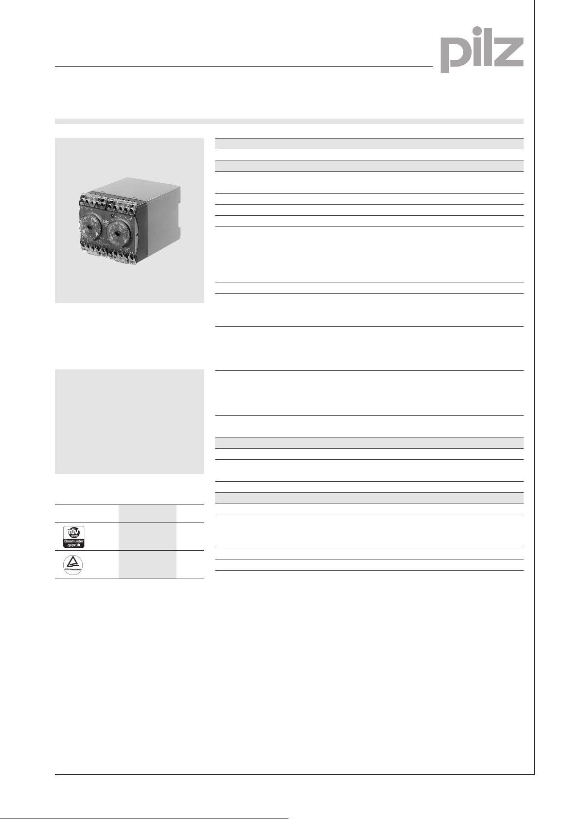
PDWZ
Technical Details PDWZ
Electrical Data
Supply Voltage AC: 110, 230 V
Tolerance 85 ... 110 %
Residual Ripple DC 20 %
Power Consumption Approx. 3.5 W/3.5 VA
Switching Capability in accordance with
EN 60947-4-1, 10/91 AC1: 240 V/6 A/1500 VA
EN 60947-5-1, 10/91 AC15: 230 V/4 A; DC13: 24 V/3 A
(DC13: 6 cycles/min.)
Output Contacts 2 safety contacts (N/O)
Hysteresis per channel
Response value Uon: 10 ... 100 % U
Speed monitor in accordance with
VDE 0113-1, 11/98, EN 60204-1,
12/97, EN 1088, 12/95 and
IEC 204-1, 11/98.
Features
● Monitors safe reduced speed
● Single or dual-channel
operation via tachogenerator
● Simultaneity monitoring
● Cable break detection
● Automatic self-test
Approval
PDWZ
●
●
Release value U
Measuring Ranges 25 ... 250 mV; 50 ... 500 mV; 0.5 ... 5 V
Maximum overload (100 % CD) 50 V; 50 V; 200 V
Impedance 21 kW; 21 kW; 180 kW
Frequency 30 ... 400 Hz
Meas. Ranges (positive voltage only) 25 ... 250 V; 0.5 ... 5 V
Maximum overload (100 % CD) 300 V DC; 500 V DC
Impedance 300 kW; 460 kW
Frequency 30 ... 400 Hz
Contact Fuse Protection 6 A quick or 4 A slow
(EN 60947-5-1, 10/91)
Times
Delay-on De-energisation Approx. 50 ms
Delay-on Energisation after Approx. 0.3 s
supply voltage is applied
Simultaneity channel 1/2 Approx. 0.5 s
Mechanical Data
Torque Setting on Connection Terminals 1.2 Nm (screws)
Maximum Cross Section of 2 x 2.5 mm
External Conductors Single-core or multi-core with
Dimensions (H x W x D) 87 x 90 x 115 mm
Weight AC: 600 g, DC: 500 g
DC: 24 V
DC1: 24 V/6 A/150 W
: 0.8 x U
off
crimp connectors
N
on
2
5
Description
● 90 mm P-75 housing, DIN-Rail
mounting
● Positive-guided relay outputs:
– 2 safety contacts (N/O)
Operating Modes
● Single-channel operation
● Dual-channel operation
● Automatic reset
● Manual reset
● LEDs for power, fault at
channel 1/2
● Versions available with different
tacho voltages
● Increase in the number of
safety contacts available by
connecting expander modules.
Pilz GmbH & Co., Felix-Wankel-Straße 2, 73760 Ostfildern, Deutschland NSG-D-2-088-01/01
Telefon +49 (7 11) 34 09-0, Telefax +49 (7 11) 34 09-1 33, E-Mail: pilz.gmbh@pilz.de
5-1
Page 2
Safe Monitoring Relays
Speed
PDWZ
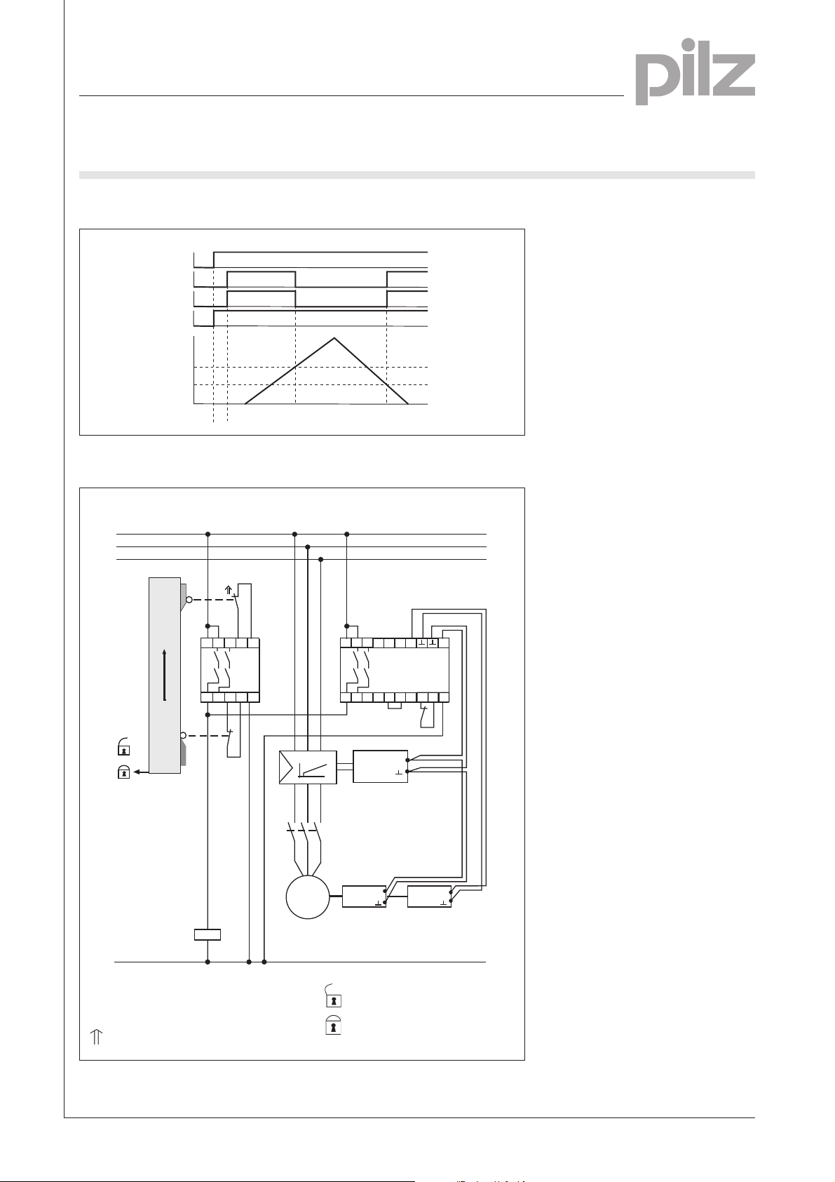
Function Diagram
U
B
13-14
22-24
Y1-Y2
U1/U2
U
an
U
ab
t
s
Connection Example
5
L1
L2
L3
S1
S14
S13
A1
23
13
PST1
S24
A2
S23
24
14
S2
n
K1
K1
N
speed regulation
M
A1 13 23
24
14
Tacho
N C
U2
U1
PDWZ
A2
Y1 Y2
Y3
N
K1
O
O
Tacho
O
S1/S2: E-STOP or safety gate switch
Gate open
Gate closed
Switch operated
Pilz GmbH & Co., Felix-Wankel-Straße 2, 73760 Ostfildern, Deutschland NSG-D-2-088-01/01
Telefon +49 (7 11) 34 09-0, Telefax +49 (7 11) 34 09-1 33, E-Mail: pilz.gmbh@pilz.de
Page 3

Safe Monitoring Relays
Speed
PDWZ
General Technical Data
Unless stated otherwise in the technical details for the specific unit
Electrical Data
Frequency Range AC 50 ... 60 Hz
Residual Ripple DC 160 %
Contact Material AgSnO
Continuous Duty 100 %
Environmental Data
EMC EN 50081-1, 01/92, EN 50082-2, 03/95
Vibration in accordance with Frequency: 10 ... 55 Hz,
EN 60068-2-6, 04/95 Amplitude: 0.35 mm
Climatic Suitability DIN IEC 60068-2-3, 12/86
Airgap Creepage DIN VDE 0110 part 1, 04/97
Ambient Temperature -10 ... +55 °C
Storage Temperature -40 ... +85 °C
Mechanical Data
Torque Setting on Connection Terminals 0.6 Nm (screws)
Mounting Position Any
Housing Material Thermoplast Noryl SE 100
Protection Mounting: IP 54
2
Housing: IP 40
Terminal Range: IP 20
The units were tested in accordance with the relevant standards current at
the time of development.
Order References
Type U
PDWZ UB 110 V AC / UM 250 V DC 407 793
PDWZ UB 110 V AC / UM 5 V DC 407 785
PDWZ UB 230 V AC / UM 5 V DC 407 789
PDWZ UB 230 V AC / UM 250 V DC 407 790
PDWZ UB 24 V DC / UM 250 mV DC 407 798
PDWZ UB 24 V DC / UM 250 V DC 407 792
PDWZ UB 24 V DC / UM 500 mV DC 407 797
PDWZ UB 24 V DC / UM 5 V DC 407 799
PDWZ UB 24 V DC / UM 5 V DC P500 407 795
B
Order No.
5
Pilz GmbH & Co., Felix-Wankel-Straße 2, 73760 Ostfildern, Deutschland NSG-D-2-088-01/01
Telefon +49 (7 11) 34 09-0, Telefax +49 (7 11) 34 09-1 33, E-Mail: pilz.gmbh@pilz.de
5-3
 Loading...