

Page 1

Operating Manual PDP67 F 8DI ION HP
Operating Manual PDP67 F 8DI ION HP
PDP67 F 8DI ION HP
Decentralised periphery
Operating Manual — No. 1002225-EN-03
Page 2

This document is a translation of the original document.
All rights to this documentation are reserved by Pilz GmbH & Co. KG. Copies may be made
for internal purposes.
Suggestions and comments for improving this documentation will be gratefully received.
Pilz®, PIT®, PMI®, PNOZ®, Primo®, PSEN®, PSS®, PVIS®, SafetyBUS p®, SafetyEYE®,
SafetyNET p®, the spirit of safety® are registered and protected trademarks of
Pilz GmbH & Co. KG in some countries.
SD means Secure Digital.
Preface
Page 3

Contents
Contents
Contents Page
Chapter 1 Introduction
1.1 Validity of documentation 1-1
1.1.1 Retaining the documentation 1-1
1.2 Overview of documentation 1-2
1.3 Definition of symbols 1-3
Chapter 2 Overview
2.1 Unit structure 2-1
2.1.1 Scope of supply 2-1
2.1.2 Unit features 2-1
2.2 Front view 2-2
Chapter 3 Safety
3.1 Intended use 3-1
3.2 Safety regulations 3-2
3.2.1 Use of qualified personnel 3-2
3.2.2 Warranty and liability 3-2
3.2.3 Disposal 3-2
Chapter 4 Function description
4.1 Unit properties 4-1
4.1.1 Operation 4-1
4.1.1.1 Inputs 4-1
4.1.1.2 Outputs 4-1
4.1.2 Data download 4-1
4.1.3 Diagnostics 4-2
Chapter 5 Installation
5.1 General installation guidelines 5-1
5.1.1 Dimensions 5-1
Chapter 6 Supply Voltage
Chapter 7 Wiring
7.1 General wiring guidelines 7-1
7.2 Connector pin assignment 7-2
7.3 Wiring examples 7-4
7.3.1 Example: Single-channel, failsafe input device, without test pulse
7.3.2 Example: Dual-channel input devices,
without test pulses
7.3.3 Example: Single-channel, failsafe input device, with test pulse
Pilz GmbH & Co. KG, Felix-Wankel-Straße 2, 73760 Ostfildern, Germany
Telephone: +49 711 3409-0, Telefax: +49 711 3409-133, E-Mail: pilz.gmbh@pilz.de
7-4
7-5
7-7
1
Page 4

Contents
7.3.4 Example: Dual-channel, failsafe input device, with test pulse
Chapter 8 Operation
8.1 Messages 8-1
8.1.1 Display elements for device diagnostics 8-1
Chapter 9 Technical details
9.1 Technical details 9-1
9.2 Order reference 9-4
7-8
Pilz GmbH & Co. KG, Felix-Wankel-Straße 2, 73760 Ostfildern, Germany
2
Telephone: +49 711 3409-0, Telefax: +49 711 3409-133, E-Mail: pilz.gmbh@pilz.de
Page 5

1 Introduction
1.1 Validity of documentation
11000IntroductionIntroduction1-1.1Validity of docume ntation1100Validity of documenta tion1-Einf Gltigkeit der Dokumentati onPDP67_VA
This documentation is valid for the products PDP67 F 8DI ION HP,
PDP67 F 8DI ION HP VA. It is valid until new documentation is pub-
Einf Einleitung
1.1.1 Retaining the documentation
Retaining the documentation1-Einf Aufbewahren
lished.
This operating manual explains the function and operation, describes
the installation and provides guidelines on how to connect the product.
This documentation is intended for instruction and should be retained
for future reference.
Pilz GmbH & Co. KG, Felix-Wankel-Straße 2, 73760 Ostfildern, Germany
Telephone: +49 711 3409-0, Telefax: +49 711 3409-133, E-Mail: pilz.gmbh@pilz.de
1-1
Page 6

1 Introduction
1.2 Overview of documentation
1.2Overview of documentation1200Overview of documentation1-][BA Einf Übersicht PDP
1 Introduction
The introduction is designed to familiarise you with the contents, structure and specific order of this manual.
2 Overview
This chapter provides information on the product's most important features.
3 Safety
This chapter must be read as it contains important information on intended use.
4 Function Description
This chapter describes the product's individual components.
5 Installation
This chapter explains how to install the product.
6 Supply Voltage
This chapter explains what you need to consider when connecting the
supply voltage.
7 Wiring
This chapter describes the product's wiring.
8 Operation
This chapter explains the display elements and advises on what to do if
a fault occurs.
1-2
9 Technical Details
This chapter contains the product's technical details and order reference.
Pilz GmbH & Co. KG, Felix-Wankel-Straße 2, 73760 Ostfildern, Germany
Telephone: +49 711 3409-0, Telefax: +49 711 3409-133, E-Mail: pilz.gmbh@pilz.de
Page 7
1 Introduction
1.3 Definition of symbols
1.3Definition of symbols1300Definition of symbols1-Einfhrung Zeichen
Information that is particularly important is identified as follows:
DANGER!
This warning must be heeded! It warns of a hazardous situation
that poses an immediate threat of serious injury and death and
indicates preventive measures that can be taken.
WARNING!
This warning must be heeded! It warns of a hazardous situation
that could lead to serious injury and death and indicates preventive measures that can be taken.
CAUTION!
This refers to a hazard that can lead to a less serious or minor
injury plus material damage, and also provides information on
preventive measures that can be taken.
NOTICE
This describes a situation in which the unit(s) could be damaged
and also provides information on preventive measures that can
be taken. It also highlights areas within the text that are of particular importance.
INFORMATION
This gives advice on applications and provides information on
special features.
Pilz GmbH & Co. KG, Felix-Wankel-Straße 2, 73760 Ostfildern, Germany
Telephone: +49 711 3409-0, Telefax: +49 711 3409-133, E-Mail: pilz.gmbh@pilz.de
1-3
Page 8

1 Introduction
1-4
Pilz GmbH & Co. KG, Felix-Wankel-Straße 2, 73760 Ostfildern, Germany
Telephone: +49 711 3409-0, Telefax: +49 711 3409-133, E-Mail: pilz.gmbh@pilz.de
Page 9

2 Overview
2.1 Unit structure
22000OverviewOverview2-2.1Unit structure2100Unit structure2-
2.1.1 Scope of supply
Scope of supply2-Eigenschaften
2.1.2 Unit features
Unit features2-Gerätemerkmale_Verwendung_PDP_VA
Verwendung/Bildunterschrift_PDP_DI
Geraetemerkmale_Zusatz BA Einleitung
Decentralised input module PDP67 F 8DI ION HP/PDP67 F 8DI ION
HP VA
4 blind plugs 380 324
Application of the products PDP67 F 8DI ION HP, PDP67 F 8DI ION
HP VA:
Decentralised input module for connection to a Pilz control system, for
use in a rugged industrial environment up to protection type IP67.
Gertemerkmale_PDP_IP67
The product has the following features:
Protection type IP67
8 inputs for connecting 8 single-channel or 4 dual-channel sensors
8 outputs, which can be configured as
– Standard outputs
– test pulse outputs
– 24 V outputs
Separate output supply for applications with higher current consump-
tion
Module is galvanically isolated from CAN bus
LED for:
– Operating state
– Errors
– Connection status
– Supply voltage
– Input status at each input
Pilz GmbH & Co. KG, Felix-Wankel-Straße 2, 73760 Ostfildern, Germany
Telephone: +49 711 3409-0, Telefax: +49 711 3409-133, E-Mail: pilz.gmbh@pilz.de
2-1
Page 10
2 Overview
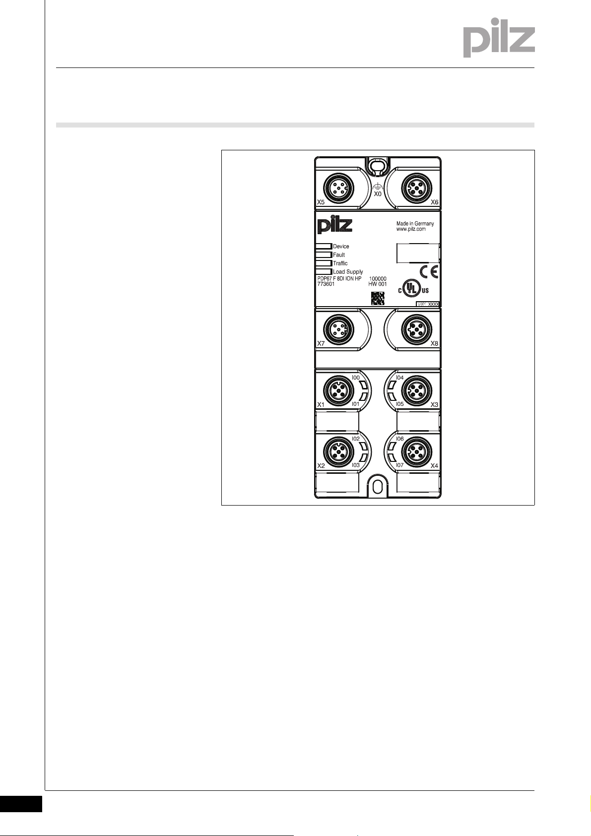
2.2 Front view
2.2Front view2200Front view2-Klemmenbelegung PDP67 8DI ION HP
2-2
Legende PDP IP67
Legend:
X1 ... X4:
Inputs
X5:
Interface to the control system or to X6 on the upstream module
X6:
Interface to X5 on the downstream module
X7:
Interface to the 24 V supply or to X8 on the upstream module
X8:
Interface to the 24 V supply or to X7 on the downsteam module
LEDs:
–Device
–Fault
–Traffic
– Load Supply
– IO0 ... IO7
Pilz GmbH & Co. KG, Felix-Wankel-Straße 2, 73760 Ostfildern, Germany
Telephone: +49 711 3409-0, Telefax: +49 711 3409-133, E-Mail: pilz.gmbh@pilz.de
Page 11

3 Safety
3.1 Intended use
33000SafetySafety3-3.1Intended use3100Intended use3-Bestimmung/Gertebeschreibung_PDP_DI
Bestimmung/Gertebeschreibung_PDP_DI_HP_Anschluss_Multi
Bestimmung/Gerätebeschreibung_EMV+Ausschluss
The products PDP67 F 8DI ION HP, PDP67 F 8DI ION HP VA are decentralised input modules designed for use in a rugged industrial environment up to protection type IP67.
The module can be connected to a link module PNOZ ml2p or PNOZ
mml2p from the configurable control system PNOZmulti.
Intended use includes making the electrical installation EMC-compliant.
The product is designed for use in an industrial environment. It is not
suitable for use in a domestic environment, as this can lead to interference.
The following is deemed improper use in particular:
Any component, technical or electrical modification to the product
Use of the product outside the areas described in this manual
Use of the product outside the technical details (see chapter entitled
“Technical Details”)
Pilz GmbH & Co. KG, Felix-Wankel-Straße 2, 73760 Ostfildern, Germany
Telephone: +49 711 3409-0, Telefax: +49 711 3409-133, E-Mail: pilz.gmbh@pilz.de
3-1
Page 12

3 Safety
3.2 Safety regulations
3.2Safety regulations3200Safety regulations3-
3.2.1 Use of qualified personnel
Use of qualified personnel3-Sich Qualif. Personal
The products may only be assembled, installed, programmed, commissioned, operated, maintained and decommissioned by competent persons.
A competent person is someone who, because of their training, experience and current professional activity, has the specialist knowledge required to test, assess and operate the work equipment, devices,
systems, plant and machinery in accordance with the general standards
and guidelines for safety technology.
It is the company's responsibility only to employ personnel who:
Are familiar with the basic regulations concerning health and safety /
accident prevention
Have read and understood the safety guidelines given in this descrip-
tion
Have a good knowledge of the generic and specialist standards ap-
plicable to the specific application.
3.2.2 Warranty and liability
Warranty and liability3-Sich Gewhrleistung_ohne_Veränderungen...
3.2.3 Disposal
Disposal3-Si ch Entsorgung
All claims to warranty and liability will be rendered invalid if:
The product was used contrary to the purpose for which it is intended
Damage can be attributed to not having followed the guidelines in the
manual or
Operating personnel are not suitably trained.
In safety-related applications, please comply with the mission time t
M
in the safety-related characteristic data.
When decommissioning, please comply with local regulations regard-
ing the disposal of electronic devices (e.g. Electrical and Electronic
Equipment Act).
3-2
Pilz GmbH & Co. KG, Felix-Wankel-Straße 2, 73760 Ostfildern, Germany
Telephone: +49 711 3409-0, Telefax: +49 711 3409-133, E-Mail: pilz.gmbh@pilz.de
Page 13

4 Function description
4.1 Unit properties
44000Function descriptionFunction description4-4.1Unit properties4100Unit properties4-
4.1.1 Operation
Operation4-Funktionen_PDP_DI_Konfiguration
The functions of the inputs and outputs are configured in the system
software.
4.1.1.1 Inputs
Inputs4-Funktionen_PDP_DI_Eingänge
Single and dual-channel sensors can be connected to the inputs, with
or without test pulses.
Input signals must show a “High” (“1” signal) of 15 VDC (+15 ... +30 VDC)
and a “Low” (“0” signal) of 0 VDC (-3 ... +5 VDC).
4.1.1.2 Outputs
Outputs4-Funktionen_PDP_DI_Ausgänge
The input status is signalled to the control system via the bus.
Green LEDs indicate the status of the inputs.
Test pulses can be used to check the inputs for shorts across contacts
and correct functionality.
The outputs can be used as standard outputs, as test pulse outputs or
as 24 VDC outputs.
The test pulse outputs are suitable for testing the sensor wiring. All safety-related inputs must operate in accordance with the failsafe principle
(on switching off).
Two test pulses are available on each plug-in connector; these test pulses are permanently assigned to the inputs. The assignment of the test
pulses to the inputs cannot be changed in the system software's configurator.
If the test pulse outputs are not being used, they can be configured as
standard outputs or 24 VDC outputs in the system software's configurator.
Pilz GmbH & Co. KG, Felix-Wankel-Straße 2, 73760 Ostfildern, Germany
Telephone: +49 711 3409-0, Telefax: +49 711 3409-133, E-Mail: pilz.gmbh@pilz.de
4-1
Page 14

4 Function description
4.1 Unit properties
4.1.2 Data download
Data download4-Funktionen_PDP_Datenübertragung
Communication with the control system is via a safe data link. Data is
exchanged cyclically.
4.1.3 Diagnostics
Diagnostics4-Funktionen_PDP_DI_Diagnose
The status and error messages shown by the LEDs are saved in an error
stack. The system software can read this error stack.
4-2
Pilz GmbH & Co. KG, Felix-Wankel-Straße 2, 73760 Ostfildern, Germany
Telephone: +49 711 3409-0, Telefax: +49 711 3409-133, E-Mail: pilz.gmbh@pilz.de
Page 15

5 Installation
29,6
5,6
22,1
60
162
37
125
58
29
5.1 General installation guidelines
55000InstallationInstallation5-5.1General installation guidelines5100General installation guidelines5-Montagefläche_PDP
The product must be fastened to a flat mounting surface, so that there
is no strain on the housing when the module is screwed down. The
mounting distances will depend on which plug-in connectors are used
and on the bending radius of the cables.
Montage_PDP - Vorgehensweise
Montage_PDP - Vorgehensweise_Funktionserde an Schraube
Unused connectors should be sealed using blind plugs.
To install the system, proceed as follows:
Fit 2 x M4 internal threads on the mounting surface.
Use two fixing screws to attach the product to the mounting plate.
With shielded cables, connect the functional earth to the upper fixing
screw X0.
5.1.1 Dimensions
Dimensions5-Abmessungen_PDP 67_8DI ION_HP
Pilz GmbH & Co. KG, Felix-Wankel-Straße 2, 73760 Ostfildern, Germany
Telephone: +49 711 3409-0, Telefax: +49 711 3409-133, E-Mail: pilz.gmbh@pilz.de
5-1
Page 16

5 Installation
5-2
Pilz GmbH & Co. KG, Felix-Wankel-Straße 2, 73760 Ostfildern, Germany
Telephone: +49 711 3409-0, Telefax: +49 711 3409-133, E-Mail: pilz.gmbh@pilz.de
Page 17

6 Supply Voltage
66000Supply VoltageSupply Voltage6-Versorgungsspannung PDP
Please note the following:
When selecting the power supply, please refer to the requirements
Overvoltage or interference voltage can damage or even destroy the
stated under “Technical Details”.
electronics on the products PDP67 F 8DI ION HP, PDP67 F 8DI ION
HP VA. The affected outputs on the control system are shut down.
You should therefore take note of the relevant EMC measures.
WARNING!
Safe electrical isolation must be ensured for the 24 V supply.
Failure to do so could result in electric shock. Power supplies
must conform to EN 60950, section 2.3, EN 60742 or EN 50178.
To achieve the lowest possible residual ripple, we recommend
that you install a three-phase bridge rectifier or regulated supply.
The “Ground” connection to the earth bar or earth fault moni-
tor must be in accordance with the relevant national regulations (e.g. EN 60204-1, NFPA 79:17-7, NEC: Article 250).
Anschluss_Weiterl PDP
INFORMATION
The module's output circuits have been designed to guarantee
maximum safety. To achieve this, extensive tests are carried out
internally. Momentary interruptions to the “Supply” voltage during a test procedure can falsify the test result, causing the following malfunction: If the “Supply” voltage is interrupted
momentarily, the unbuffered test pulse outputs will transmit a
“0” signal. The buffered module electronics reads this signal at
the pulsed inputs, thereby triggering the user's configured reaction.
Example: The system reacts as though an E-STOP button has
been operated, although this is not the case: there has been a
supply interruption.
Remedy: The “Supply” must be buffered.
Pilz GmbH & Co. KG, Felix-Wankel-Straße 2, 73760 Ostfildern, Germany
Telephone: +49 711 3409-0, Telefax: +49 711 3409-133, E-Mail: pilz.gmbh@pilz.de
6-1
Page 18

6 Supply Voltage
Supply
Supply
Use a 5-pin M12 plug-in connector to connect the module to the external supply voltage.
The module also has an M12 socket which is physically adjacent to the
M12 connector; this is used to distribute the supply voltage to other
modules.
Anschluss_Weiterl_Zeichnung PDP
Anschluss_Weiterl_Warnung PDP
Anschluss_Weiterl_Funktionserde PDP
Pinbelegung PDP
Fig. 6-1: Example for connecting and distributing the supply voltage
WARNING!
The current load capacity of the M12 plug-in connector is 4 A
per connector. You must ensure that this value is not exceeded.
Exceeding the permitted current load capacity can damage the
plug-in connector. Please note that the connection of the additional supply voltage is not monitored for overload.
INFORMATION
We recommend that you connect the functional earth to the
upper fixing screw.
6-2
Pilz GmbH & Co. KG, Felix-Wankel-Straße 2, 73760 Ostfildern, Germany
Telephone: +49 711 3409-0, Telefax: +49 711 3409-133, E-Mail: pilz.gmbh@pilz.de
Page 19

6 Supply Voltage
2
3
4
1
5
X7 (male connector)
X8 (female connector)
4
1
2
3
5
Fig. 6-2: Pin assignment for the supply voltage
Key:
1: + 24 VDC
2: + 24 VDC
3: 0 V
4: 0 V
5: n.a.
Pilz GmbH & Co. KG, Felix-Wankel-Straße 2, 73760 Ostfildern, Germany
Telephone: +49 711 3409-0, Telefax: +49 711 3409-133, E-Mail: pilz.gmbh@pilz.de
6-3
Page 20

6 Supply Voltage
6-4
Pilz GmbH & Co. KG, Felix-Wankel-Straße 2, 73760 Ostfildern, Germany
Telephone: +49 711 3409-0, Telefax: +49 711 3409-133, E-Mail: pilz.gmbh@pilz.de
Page 21

7 Wiring
7.1 General wiring guidelines
77000WiringWiring7-7.1General wiring g uidelines7100Ge neral wiring guidelin es7-Verdrahtung_PDP_DI
Please note:
Information given in the “Technical details” must be followed.
In safety-related applications, it is essential that short circuits and
open circuits are unable to cause a hazardous condition within a
plant. The way in which this is done will depend on the degree of hazard from the plant section, the switching frequency of the sensors and
the level of safety of the sensors and actuators.
Please refer to the link module's operating instructions for details of
the maximum cable length.
Pilz pre-assembled cable can be used to connect the inputs and out-
puts (see order reference).
We recommend you use pre-assembled Pilz connectors to connect
the inputs and test pulse outputs (see order reference).
CAUTION!
The supply voltages for an external device must be extra low
voltages with safe electrical separation (PELV or SELV) in
accordance with VDE 0100, Part 410.
CAUTION!
In order to guarantee protection type IP67, unused connectors
should be sealed using the blind plugs supplied.
CAUTION!
Make sure that the plug-in connectors are connected to the sensors correctly. Once you have run a function test to check that
the connectors are connected to the sensors correctly, the
inputs should be labelled. If the inputs are connected to the sensors incorrectly, life-threatening situations may arise on the
plant.
Pilz GmbH & Co. KG, Felix-Wankel-Straße 2, 73760 Ostfildern, Germany
Telephone: +49 711 3409-0, Telefax: +49 711 3409-133, E-Mail: pilz.gmbh@pilz.de
7-1
Page 22

7 Wiring
2
3
4
1
5
2
3
4
1
5
2
3
4
1
5
4
1
2
3
5
7.2 Connector pin assignment
7.2Connector pin assignment7200Connector pin assignment7-Anschluss_PDP_DI_Schnittstellenbelegung mit Versorungsspannung
Inputs/outputs
X1 to X4
5-pin M12 female connector
A-coded
Assignment
1: Test pulse x / 24 VDC / ST output.
2: Input X
3: 0 V
4: Input X + 1
5: Test pulse X + 1 / 24 VDC / ST output
Interface to the link module: X5
5 pin M12 male connector
A-coded
Interface to the next decentralised module: X6
5-pin M12 female connector
A-coded
Interface to the 24 V supply or to previous decentralised module: X7
5 pin M12 male connector
B-coded
Assignment
1: VCC
2: CAN3: GND
4: CAN+
5: Shield
Assignment
1: VCC
2: CAN3: GND
4: CAN+
5: Shield
Assignment
1: + 24 VDC
2: + 24 VDC
3: 0 V
4: 0 V
5: n.a.
7-2
Pilz GmbH & Co. KG, Felix-Wankel-Straße 2, 73760 Ostfildern, Germany
Telephone: +49 711 3409-0, Telefax: +49 711 3409-133, E-Mail: pilz.gmbh@pilz.de
Page 23

7 Wiring
2
3
4
1
5
7.2 Connector pin assignment
Interface to the 24 V supply or to next decentralised module: X8
5-pin M12 female connector
B-coded
Assignment
1: + 24 VDC
2: + 24 VDC
3: 0 V
4: 0 V
5: n.a.
Pilz GmbH & Co. KG, Felix-Wankel-Straße 2, 73760 Ostfildern, Germany
Telephone: +49 711 3409-0, Telefax: +49 711 3409-133, E-Mail: pilz.gmbh@pilz.de
7-3
Page 24

7 Wiring
7.3 Wiring examples
7.3Wiring examples7300Wiring examples7-
7.3.1 Example: Single-channel, failsafe input device, without test pulse
Example: Single-channel, failsafe input device, without test pulse7-Bsp 1: einkan fehlersich Sensor ungetaktet
Features:
Depending on the application area and its respective regulations, this
connection diagram is suitable for input devices with frequent and
infrequent operation in accordance with EN ISO 13849-1 up to PL
d and EN IEC 62061 up to SIL CL 2.
The input device must be approved for failsafe applications.
Bsp: WARNUNG Kurzschluss Bsp. 1
Please read the instructions provided with the input device.
WARNING!
Short circuits between the cable to the input device and the 24 V
line or between cables to various input devices will not be
detected. Depending on the application, serious injury or death
may result.
Avoid short circuits by
Appropriate wiring
Wiring in accordance with the requirements of IEC 61076-2-
101 and IEC 60204-1, clause 14.1.1 and 14.1.2
Bsp 1: einkan fehlersich Sensor ungetaktet_Zeichnung HP
7-4
Pilz GmbH & Co. KG, Felix-Wankel-Straße 2, 73760 Ostfildern, Germany
Telephone: +49 711 3409-0, Telefax: +49 711 3409-133, E-Mail: pilz.gmbh@pilz.de
Page 25

7 Wiring
24 V
L+
L-
24 V
Single-channel, failsafe input device
Please ensure safety regulations and EMC guidelines are met!
7.3 Wiring examples
Pilz GmbH & Co. KG, Felix-Wankel-Straße 2, 73760 Ostfildern, Germany
Telephone: +49 711 3409-0, Telefax: +49 711 3409-133, E-Mail: pilz.gmbh@pilz.de
7-5
Page 26

7 Wiring
7.3 Wiring examples
7.3.2 Example: Dual-channel input devices, without test pulses
Example: Dual-channel input devices, without test pulses7-Bsp 2: zweikan Sensor ungetaktet
Features:
This type of connection is mainly used for signal inputs with frequent
operation.
Depending on the application area and its respective regulations, this
connection diagram is suitable for input devices with frequent operation and diverse channels in accordance with EN ISO 13849-1 up
to PL e and EN IEC 62061 up to SIL CL 3, provided the functionality
of both input device channels is monitored in the user program via a
feasibility check.
The input device must be approved for failsafe applications.
If you are using input devices with different (diverse) channels, adja-
cent inputs may be used. The user program will detect short circuits
Bsp: WARNUNG Kurzschluss Bsp. 2
via the feasibility check.
Bsp 2: zweikan Sensor ungetaktet_Zeichnung HP
WARNING!
On input devices with identical channels, short circuits between
the cable to the input device and the 24 V line or between cables
to both input devices will not be detected. Depending on the
application, serious injury or death may result.
Avoid short circuits by
Appropriate wiring
Wiring in accordance with the requirements of IEC 61076-2-
101 and IEC 60204-1, clause 14.1.1 and 14.1.2
7-6
Pilz GmbH & Co. KG, Felix-Wankel-Straße 2, 73760 Ostfildern, Germany
Telephone: +49 711 3409-0, Telefax: +49 711 3409-133, E-Mail: pilz.gmbh@pilz.de
Page 27

7 Wiring
24 V
L+
L-
Dual-channel input device
with different
(diverse) channels
Please ensure safety regulations and EMC guidelines are met!
24 V
24 V
7.3 Wiring examples
7.3.3 Example: Single-channel, failsafe input device, with test pulse
Example: Single-channel, failsafe input device, with test pulse7-Bsp 3: einkan fehlersich Sensor getaktet
Bsp: ACHTUNG Kurzschluss Bsp. 3
Pilz GmbH & Co. KG, Felix-Wankel-Straße 2, 73760 Ostfildern, Germany
Telephone: +49 711 3409-0, Telefax: +49 711 3409-133, E-Mail: pilz.gmbh@pilz.de
Features:
Depending on the application area and its respective regulations, this
connection diagram is suitable in accordance with EN ISO 13849-1
up to PL d and EN IEC 62061 up to SIL CL 2.
The input device must be approved for failsafe applications.
Test pulses can be used to check the inputs for short circuit to 24 V
and correct functionality. Short circuits that short out the input device
(cable from the test pulse to the input device and cable from the input
device to the input) will not be detected.
Please read the instructions provided with the input device.
Only input devices with N/C contacts can be tested.
7-7
Page 28

7 Wiring
24 V
L+
L-
Test pulse T0
Single-channel, failsafe input device
Please ensure safety regulations and EMC guidelines are met!
7.3 Wiring examples
Bsp 3: einkan fehlersich Sensor getaktet_Zeichnung HP
CAUTION!
Short circuits between the cable to the input device and the 24 V
line or between cables to various input devices will not be
detected.
Avoid short circuits by
Appropriate wiring
Wiring in accordance with the requirements of IEC 61076-2-
101 and IEC 60204-1, clause 14.1.1 and 14.1.2
7-8
Pilz GmbH & Co. KG, Felix-Wankel-Straße 2, 73760 Ostfildern, Germany
Telephone: +49 711 3409-0, Telefax: +49 711 3409-133, E-Mail: pilz.gmbh@pilz.de
Page 29

7 Wiring
24 V
L+
L-
Dual-channel input device
with diverse channels
Please ensure safety regulations and EMC guidelines are met!
Test pulse T1
Test pulse T0
Test pulse T1
Test pulse T0
Dual-channel input device
with identical channels
7.3 Wiring examples
7.3.4 Example: Dual-channel, failsafe input device, with test pulse
Example: Dual-channel, failsafe input device, with test pulse7-Bsp 4: zweikan fehlersich Sensor getaktet
Features:
Depending on the application area and its respective regulations, this
connection diagram is suitable in accordance with EN ISO 13849-1
up to PL e and EN IEC 62061 up to SIL CL 3.
The input device must be approved for failsafe applications.
This type of connection is mainly used for signal inputs with infrequent
operation.
As the test pulses are permanently assigned to the inputs, all short
circuits will be detected, with the exception of short circuits that short
out the input device (cable from the test pulse to the input device and
Bsp 4: zweikan fehlersich Sensor getaktet_Zeichnung HP
cable from the input device to the input).
Pilz GmbH & Co. KG, Felix-Wankel-Straße 2, 73760 Ostfildern, Germany
Telephone: +49 711 3409-0, Telefax: +49 711 3409-133, E-Mail: pilz.gmbh@pilz.de
7-9
Page 30

7 Wiring
7-10
Pilz GmbH & Co. KG, Felix-Wankel-Straße 2, 73760 Ostfildern, Germany
Telephone: +49 711 3409-0, Telefax: +49 711 3409-133, E-Mail: pilz.gmbh@pilz.de
Page 31

8 Operation
8.1 Messages
88000OperationOperation8-8.1Messages81 00Messages8-Betr ieb_Meldungen_PDP _DI
The module is ready for operation when the "Ready" LED on the link
module is lit continuously.
8.1.1 Display elements for device diagnostics
Display elements for device diagnostics 8-Anzeige Legende 3x
Legend:
Betrieb_Anzeige_PDP_DI_ HP
LED on
LED flashes
LED off
LED LED status Meaning
Device Green The unit is ready for operation
The unit is not ready for operation
FAULT Red Internal error
No error
Traffic Yellow Connection to control system established
Yellow Error in the connection to the control system. Flashing stops a max. of 1 min.
after the fault has been rectified.
No connection to control system established
Input LEDs Green 1 signal is present
Green Link module has detected a pulse error.
Once the fault has been rectified, the decentralised input module will continue
to work normally after a wait of just a few seconds.
0 signal is present
Load Supply Yellow Voltage is present
Yellow The supply voltage is/was too low.
Once the fault has been rectified, the LED will not stop flashing until the system
has been switched off and then on again.
Voltage is missing
Pilz GmbH & Co. KG, Felix-Wankel-Straße 2, 73760 Ostfildern, Germany
Telephone: +49 711 3409-0, Telefax: +49 711 3409-133, E-Mail: pilz.gmbh@pilz.de
8-1
Page 32

8 Operation
8-2
Pilz GmbH & Co. KG, Felix-Wankel-Straße 2, 73760 Ostfildern, Germany
Telephone: +49 711 3409-0, Telefax: +49 711 3409-133, E-Mail: pilz.gmbh@pilz.de
Page 33

9 Technical details
9.1 Technical details
99000Technical detailsTechnical details9-9.1Technical details9100Technical details9-][Technische Daten_PDP_DI
Technical details
Application range Standard/Failsafe
Electrical data
Internal supply voltage Supply
Supply voltage U
Voltage tolerance -30 %/+25 %
Power consumption at U
Inputs
Number 8
Input voltage 24 V DC
Input current 3.0 mA
Potential isolation between input and internal bus voltage yes
Outputs (configurable as semiconductor outputs or
test pulse outputs)
Infeed for Load Supply
Voltage 24 V DC
Voltage tolerance -30 %/+25 %
Max. continuous current that the external power supply
must provide
Max. unit fuse protection F1 4 A
Max. unit fuse protection F1 in according with UL508 4 A
Number of positive-switching single-pole semiconductor
outputs
Short circuit-proof yes
Potential isolation between semiconductor output and in-
ternal bus voltage
Potential isolation between semiconductor output and input
Typ. output current at “1” signal and rated voltage of sem-
iconductor output
Permitted current range 0.00 - 0.60 A
Residual current at “0” signal 0.02 mA
Permitted loads inductive, capacitive, resistive
Max. internal voltage drop 200 mV
Terminal voltage when switching off inductive loads -45 V
Number of test pulse outputs 8
Number of outputs that can be configured as test pulses 8
Max. output current at “1” signal 0.50 A
Short circuit-proof yes
Max. cable runs between test pulse output and input 20 m
Hardware processing times
Max. processing time for input when signal changes from
“1” to “0”
Max. processing time for input when signal changes from
“0” to “1”
Min. processing time for input when signal changes from
“1” to “0”
Min. processing time for input when signal changes from
“0” to “1”
DC 24 V
B
B
1.2 W
4.0 A
8
yes
no
0.50 A
1.000 ms
1.200 ms
0.50 ms
0.70 ms
Pilz GmbH & Co. KG, Felix-Wankel-Straße 2, 73760 Ostfildern, Germany
Telephone: +49 711 3409-0, Telefax: +49 711 3409-133, E-Mail: pilz.gmbh@pilz.de
9-1
Page 34

9 Technical details
9.1 Technical details
Environmental data
Climatic suitability EN 60068-2-78
Ambient temperature in accordance with EN 60068-2-14 -30 - 60 °C
Storage temperaturein accordance withEN 60068-2-1/-2 -40 - 70 °C
Climatic suitability in accordance with EN 60068-2-78 93 % r. h. at 40 °C
Condensation temporary No. 773601
EMC EN 55011: class A, EN 61000-4-11, EN 61000-4-2, EN
61000-4-3, EN 61000-4-4, EN 61000-4-5, EN 61000-4-6,
EN 61000-4-8, EN 61000-4-9
Vibration to EN 60068-2-6
Frequency 10 - 55 Hz
Max. acceleration 1g
Shock stress
EN 60068-2-27 15g
11 ms
EN 60068-2-29 10g
16 ms
Protection typein accordance withEN 60529
Housing IP67
Terminals IP67
Airgap creepage in accordance with IEC 60664-1
Overvoltage category III
Pollution degree 2
Mechanical data
Connection type M12 No. 773601
Stainless steel 1.4305 No. 773615
Housing material
Top Valox 855
Labelling bracket (accessories) PC
Dimensions
Height 162.0 mm
Width 60.0 mm
Depth 30.0 mm
Weight 375 g
Si-Kennzahlen_alle
Safety characteristic data
9-2
Unit Operating mode EN ISO 13849-
1: 2006
EN 954-1
Category
EN IEC 62061
SIL CL
PFH [1/h] EN ISO
PL
Input
SC inputs single-channel PL d (Cat. 2) Cat. 2 SIL CL 2 9.06E-09 20
SC inputs dual-channel PL e (Cat. 4) Cat. 4 SIL CL 3 1.24E-09 20
Bus interface
Bus interface PL e (Cat. 4) Cat. 4 SIL CL 3 1.94E-09 20
Si_Kennzahlen_Erläuterung_1
All the units used within a safety function must be considered when cal-
Technische Daten_Satz No rmen
culating the safety characteristic data.
The standards current on 2010-03 apply.
Pilz GmbH & Co. KG, Felix-Wankel-Straße 2, 73760 Ostfildern, Germany
Telephone: +49 711 3409-0, Telefax: +49 711 3409-133, E-Mail: pilz.gmbh@pilz.de
13849-1:
2006
[year]
T
M
Page 35

9 Technical details
9.2 Order reference
9.2Order reference9200Order reference9-Bestelldaten PDP67 F 8DI ION HP
Order reference
Product type Features Order no.
PDP67 F 8DI ION HP Decentralised input module 773 601
PDP67 F 8DI ION HP VA Decentralised input module, V2A ring nut 773 615
Bestelldaten Zubehör PD P67 F 8DI ION HP
Order reference: Accessories for PDP67 F 8DI ION HP
Product type Features Order no.
Caps for IP67 modules Blind plugs 380 324
Order reference: Cable
Product type Features Order no.
PSS SB BUSCABLE LC Cable, shielded 1 - 100 m 311 074
PSS67 I/O Cable Cable 1 - 30 m 380 320
PSS67 Cable M8sf M12sm Cable, straight M12 connector, straight M8 socket, 4-pin 3 m 380 200
PSS67 Cable M8sf M12sm Cable, straight M12 connector, straight M8 socket, 4-pin 5 m 380 201
PSS67 Cable M8sf M12sm Cable, straight M12 connector, straight M8 socket, 4-pin 10 m 380 202
PSS67 Cable M8sf M12sm Cable, straight M12 connector, straight M8 socket, 4-pin 30 m 380 203
PSS67 Cable M8sf M12sm Cable, straight M12 connector, angled M8 socket, 4-pin 3 m 380 204
PSS67 Cable M8sf M12sm Cable, straight M12 connector, angled M8 socket, 4-pin 5 m 380 205
PSS67 Cable M8sf M12sm Cable, straight M12 connector, angled M8 socket, 4-pin 10 m 380 206
PSS67 Cable M8sf M12sm Cable, straight M12 connector, angled M8 socket, 4-pin 30 m 380 207
PSS67 Cable M12sf
M12sm
PSS67 Cable M12sf
M12sm
PSS67 Cable M12sf
M12sm
PSS67 Cable M12sf
M12sm
PSS67 Cable M12sf
M12sm
PSS67 Cable M12sf
M12sm
PSS67 Cable M12sf
M12sm
PSS67 Cable M12sf
M12sm
PSS67 Supply Cable IN sf
OUT sm
PSS67 Supply Cable IN sf
OUT sm
PSS67 Supply Cable IN sf
OUT sm
PSS67 Supply Cable IN af
OUT am
Cable, straight M12 connector, straight M12 socket, 5-pin 3 m 380 208
Cable, straight M12 connector, straight M12 socket, 5-pin 5 m 380 209
Cable, straight M12 connector, straight M12 socket, 5-pin 10 m 380 210
Cable, straight M12 connector, straight M12 socket, 5-pin 30 m 380 211
Cable, angled M12 connector, angled M12 socket, 5-pin 3 m 380 212
Cable, angled M12 connector, angled M12 socket, 5-pin 5 m 380 213
Cable, angled M12 connector, angled M12 socket, 5-pin 10 m 380 214
Cable, angled M12 connector, angled M12 socket, 5-pin 30 m 380 215
Cable, IN socket straight, OUT connector straight, B-coded 3 m 380 250
Cable, IN socket straight, OUT connector straight, B-coded 5 m 380 251
Cable, IN socket straight, OUT connector straight, B-coded 10 m 380 252
Cable, IN socket angled, OUT connector angled, B-coded 3 m 380 253
Pilz GmbH & Co. KG, Felix-Wankel-Straße 2, 73760 Ostfildern, Germany
Telephone: +49 711 3409-0, Telefax: +49 711 3409-133, E-Mail: pilz.gmbh@pilz.de
9-3
Page 36

9 Technical details
9.2 Order reference
Product type Features Order no.
PSS67 Supply Cable IN af
OUT am
PSS67 Supply Cable IN af
OUT am
PSS67 Supply Cable IN sf Cable, IN socket straight, B-coded 3 m 380 256
PSS67 Supply Cable IN sf Cable, IN socket straight, B-coded 5 m 380 257
PSS67 Supply Cable IN sf Cable, IN socket straight, B-coded 10 m 380 258
PSS67 Supply Cable IN af Cable, IN socket angled, B-coded 3 m 380 259
PSS67 Supply Cable IN af Cable, IN socket angled, B-coded 5 m 380 260
PSS67 Supply Cable IN af Cable, IN socket angled, B-coded 10 m 380 261
Order reference: Adapters
Cable, IN socket angled, OUT connector angled, B-coded 5 m 380 254
Cable, IN socket angled, OUT connector angled, B-coded 10 m 380 255
Product type Features Order no.
PSEN ma adapter Adapter for connection to safety switch PSENmag 380 300
PSEN cs adapter Adapter for connection to safety switch PSENcode 380 301
Order reference: Connectors
Product type Features Order no.
PSS67 M12 connector Connector, M12, straight, 5-pin, A-coded 380 308
PSS67 M12 connector Socket, M12, straight, 5-pin, A-coded 380 309
PSS67 M12 connector Connector, M12, angled, 5-pin, A-coded 380 310
PSS67 M12 connector Socket, M12, angled, 5-pin, A-coded 380 311
PSS67 M8 connector Connector, M8, straight, 4-pin 380 316
PSS67 M8 connector Socket, M8, straight, 4-pin 380 317
PSS67 M8 connector Connector, M8, angled, 4-pin 380 318
PSS67 M8 connector Socket, M8, angled, 4-pin 380 319
PSS67 M12 connector Connector, M12, straight, 5-pin, B-coded 380 312
PSS67 M12 connector Socket, M12, straight, 5-pin, B-coded 380 313
PSS67 M12 connector Connector, M12, angled, 5-pin, B-coded 380 314
PSS67 M12 connector Socket, M12, angled, 5-pin, B-coded 380 315
9-4
Pilz GmbH & Co. KG, Felix-Wankel-Straße 2, 73760 Ostfildern, Germany
Telephone: +49 711 3409-0, Telefax: +49 711 3409-133, E-Mail: pilz.gmbh@pilz.de
Page 37

...
1002225-EN-03, 2012-03 Printed in Germany
© Pilz GmbH & Co. KG, 2011
+49 711 3409-444
support@pilz.com
Pilz GmbH & Co. KG
Felix-Wankel-Straße 2
73760 Ostfildern, Germany
Telephone: +49 711 3409-0
Telefax: +49 711 3409-133
E-Mail: pilz.gmbh@pilz.de
Internet: www.pilz.com
Technical support
In many countries we are
represented by our subsidiaries
and sales partners.
Please refer to our homepage
for further details or contact our
headquarters.
InduraNET p
®
, Pilz
®
, PIT
®
, PMCprotego
®
, PMI
®
, PNOZ
®
, Primo
®
, PSEN
®
, PSS
®
, PVIS
®
, SafetyBUS p
®
, SafetyEYE
®
, SafetyNET p
®
, the spirit of safety
®
are registered and protected trademarks
of Pilz GmbH & Co. KG in some countries. We would point out that product features may vary from the details stated in this document, depending on the status at the time of publication and the scope
of the equipment. We accept no responsibility for the validity, accuracy and entirety of the text and graphics presented in this information. Please contact our Technical Support if you have any questions.
Contact address
 Loading...