

Page 1

Operating Manual PDP67 F 4 code
Operating Manual PDP67 F 4 code
PDP67 F 4 code
Decentralised periphery
Operating Manual — No. 1001531-EN-05
Page 2

This document is a translation of the original document.
All rights to this documentation are reserved by Pilz GmbH & Co. KG. Copies may be made
for internal purposes.
Suggestions and comments for improving this documentation will be gratefully received.
Pilz
®
, PIT®, PMI®, PNOZ®, Primo®, PSEN®, PSS®, PVIS®, SafetyBUS p®, SafetyEYE®,
SafetyNET p®, the spirit of safety® are registered and protected trademarks of
Pilz GmbH & Co. KG in some countries.
SD means Secure Digital.
Preface
Page 3

Contents
Contents
Contents Page
Chapter 1 Introduction
1.1 Validity of documentation 1-1
1.1.1 Retaining the documentation 1-1
1.2 Overview of documentation 1-2
1.3 Definition of symbols 1-3
Chapter 2 Overview
2.1 Unit structure 2-1
2.1.1 Range 2-1
2.1.2 Unit features 2-1
2.2 Front view 2-2
Chapter 3 Safety
3.1 Intended use 3-1
3.2 Safety regulations 3-2
3.2.1 Use of qualified personnel 3-2
3.2.2 Warranty and liability 3-2
3.2.3 Disposal 3-2
Chapter 4 Function description
4.1 Operation 4-1
4.1.1 Internal wiring diagram 4-1
4.1.2 Diagnostics 4-1
Chapter 5 Installation
5.1 General installation guidelines 5-1
5.1.1 Dimensions 5-1
Chapter 6 Wiring
6.1 General wiring guidelines 6-1
6.2 Assignment of female connectors 6-2
6.3 Preparing for operation 6-4
6.3.1 Connection 6-4
6.3.1.1 Independent circuit 6-4
6.3.1.2 Series connection of modules 6-6
Chapter 7 Operation
7.1 Messages 7-1
7.1.1 Display elements for device diagnostics 7-1
Chapter 8 Technical details
8.1 Technical details 8-1
8.2 Order reference 8-3
Pilz GmbH & Co. KG, Felix-Wankel-Straße 2, 73760 Ostfildern, Germany
Telephone: +49 711 3409-0, Telefax: +49 711 3409-133, E-Mail: pilz.gmbh@pilz.de
1
Page 4

Contents
Pilz GmbH & Co. KG, Felix-Wankel-Straße 2, 73760 Ostfildern, Germany
2
Telephone: +49 711 3409-0, Telefax: +49 711 3409-133, E-Mail: pilz.gmbh@pilz.de
Page 5

1 Introduction
1.1 Validity of documentation
11000IntroductionIntroduction1-1.1Validity of docume ntation1100Validi ty of document ation1-Einf Gltigkeit der Dokumentati onPDP67_VA
This documentation is valid for the products PDP67 F 4 code, PDP67 F
Einf Einleitung
1.1.1 Retaining the documentation
Retaining the documentation1-Einf Aufbewahren
4 code VA. It is valid until new documentation is published.
This operating manual explains the function and operation, describes
the installation and provides guidelines on how to connect the product.
This documentation is intended for instruction and should be retained
for future reference.
Pilz GmbH & Co. KG, Felix-Wankel-Straße 2, 73760 Ostfildern, Germany
Telephone: +49 711 3409-0, Telefax: +49 711 3409-133, E-Mail: pilz.gmbh@pilz.de
1-1
Page 6

1 Introduction
1.2 Overview of documentation
1.2Overview of documentation1200Overview of documentation1-Einf_Uebersicht_über_die_Doku_6_Inbetriebnahme
1 Introduction
The introduction is designed to familiarise you with the contents, structure and specific order of this manual.
2 Overview
This chapter provides information on the product's most important features.
3 Safety
This chapter must be read as it contains important information on intended use.
4 Function Description
This chapter describes the product's mode of operation.
5 Installation
This chapter explains how to install the product.
6 Commissioning
This chapter describes the product's commissioning and wiring.
7 Operation
This chapter describes how to operate the product and gives tips in the
case of a fault.
8 Technical Details
This chapter contains the product's technical details and order reference.
1-2
Pilz GmbH & Co. KG, Felix-Wankel-Straße 2, 73760 Ostfildern, Germany
Telephone: +49 711 3409-0, Telefax: +49 711 3409-133, E-Mail: pilz.gmbh@pilz.de
Page 7
1 Introduction
1.3 Definition of symbols
1.3Definition of symbols1300Definition of symbols1-Einfhrung Zeichen
Information that is particularly important is identified as follows:
DANGER!
This warning must be heeded! It warns of a hazardous situation
that poses an immediate threat of serious injury and death and
indicates preventive measures that can be taken.
WARNING!
This warning must be heeded! It warns of a hazardous situation
that could lead to serious injury and death and indicates preventive measures that can be taken.
CAUTION!
This refers to a hazard that can lead to a less serious or minor
injury plus material damage, and also provides information on
preventive measures that can be taken.
NOTICE
This describes a situation in which the unit(s) could be damaged
and also provides information on preventive measures that can
be taken. It also highlights areas within the text that are of particular importance.
INFORMATION
This gives advice on applications and provides information on
special features.
Pilz GmbH & Co. KG, Felix-Wankel-Straße 2, 73760 Ostfildern, Germany
Telephone: +49 711 3409-0, Telefax: +49 711 3409-133, E-Mail: pilz.gmbh@pilz.de
1-3
Page 8

1 Introduction
1-4
Pilz GmbH & Co. KG, Felix-Wankel-Straße 2, 73760 Ostfildern, Germany
Telephone: +49 711 3409-0, Telefax: +49 711 3409-133, E-Mail: pilz.gmbh@pilz.de
Page 9

2 Overview
2.1 Unit structure
22000OverviewOverview2-2.1Unit structure2100Unit structure2-
2.1.1 Range
Range2-Eigenschaften
2.1.2 Unit features
Unit features2-Gerätemerkmale_Verwendung_PDP_VA
Module PDP67 F 4 code/PDP67 F 4 code VA
1 adapter PDP67 Connector cs/PDP67 Connector cs VA for con-
necting the power supply for the module and sensors
5 labels
4 blind plugs for sealing unused female connectors
Verwendung/Bildunterschrift_PDP_PSEN
Geraetemerkmale_Zusatz BA Einleitung
Gertemerkmale_PDP_PSEN
Application of the products PDP67 F 4 code, PDP67 F 4 code VA:
Decentralised passive distributor for use in rugged industrial environments up to protection type IP67 for connecting PSENcode, PSENslock
and PSENini sensors to a Pilz control system.
The product has the following features:
Protection type IP67
M12 female connectors
A maximum of 4 sensors can be connected to each module
Female connectors for series connection
LED indicator for:
– Supply voltage
– Status of sensors
Pilz GmbH & Co. KG, Felix-Wankel-Straße 2, 73760 Ostfildern, Germany
Telephone: +49 711 3409-0, Telefax: +49 711 3409-133, E-Mail: pilz.gmbh@pilz.de
2-1
Page 10
2 Overview
2.2 Front view
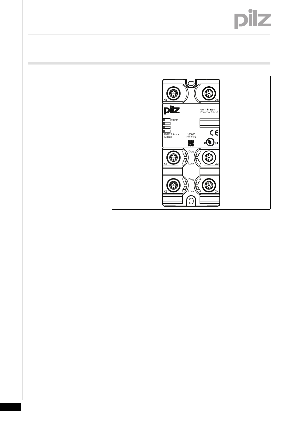
2.2Front view2200Front view2-BA_bersicht
Legende PDP PSEN
Key:
X1 ... X4:
Female connectors for connecting the sensors
X5:
Female connectors for connecting to the evaluation device (for connecting the sensors to X1 ... X4)
X6:
Female connectors for connecting signal outputs (Diag) and inputs for
control commands for magnetic guard locking (Lock)
LEDs:
–Power
–Diag
–Lock
2-2
Pilz GmbH & Co. KG, Felix-Wankel-Straße 2, 73760 Ostfildern, Germany
Telephone: +49 711 3409-0, Telefax: +49 711 3409-133, E-Mail: pilz.gmbh@pilz.de
Page 11

3 Safety
3.1 Intended use
33000SafetySafety3-3.1Intended use3100Intended use3-Verwendung/Bildunterschrift_PDP_PSEN
Bestimmung/Gerätebeschreibung_EMV+Ausschluss
Decentralised passive distributor for use in rugged industrial environments up to protection type IP67 for connecting PSENcode, PSENslock
and PSENini sensors to a Pilz control system.
Intended use includes making the electrical installation EMC-compliant.
The product is designed for use in an industrial environment. It is not
suitable for use in a domestic environment, as this can lead to interference.
The following is deemed improper use in particular:
Any component, technical or electrical modification to the product
Use of the product outside the areas described in this manual
Use of the product outside the technical details (see chapter entitled
“Technical Details”)
Pilz GmbH & Co. KG, Felix-Wankel-Straße 2, 73760 Ostfildern, Germany
Telephone: +49 711 3409-0, Telefax: +49 711 3409-133, E-Mail: pilz.gmbh@pilz.de
3-1
Page 12

3 Safety
3.2 Safety regulations
3.2Safety regulations3200Safety regulations3-
3.2.1 Use of qualified personnel
Use of qualified personnel3-Sich Qualif. Personal
The products may only be assembled, installed, programmed, commissioned, operated, maintained and decommissioned by competent persons.
A competent person is someone who, because of their training, experience and current professional activity, has the specialist knowledge required to test, assess and operate the work equipment, devices,
systems, plant and machinery in accordance with the general standards
and guidelines for safety technology.
It is the company's responsibility only to employ personnel who:
Are familiar with the basic regulations concerning health and safety /
accident prevention
Have read and understood the safety guidelines given in this descrip-
tion
Have a good knowledge of the generic and specialist standards ap-
plicable to the specific application.
3.2.2 Warranty and liability
Warranty and liability3-Sich Gewhrleistung
3.2.3 Disposal
Disposal3-Si ch Entsorgung
All claims to warranty and liability will be rendered invalid if:
The product was used contrary to the purpose for which it is intended
Damage can be attributed to not having followed the guidelines in the
manual
Operating personnel are not suitably qualified
Any type of modification has been made (e.g. exchanging compo-
nents on the PCB boards, soldering work etc.).
In safety-related applications, please comply with the mission time t
M
in the safety-related characteristic data.
When decommissioning, please comply with local regulations regard-
ing the disposal of electronic devices (e.g. Electrical and Electronic
Equipment Act).
3-2
Pilz GmbH & Co. KG, Felix-Wankel-Straße 2, 73760 Ostfildern, Germany
Telephone: +49 711 3409-0, Telefax: +49 711 3409-133, E-Mail: pilz.gmbh@pilz.de
Page 13

4 Function description
6 I1
1 I2
2 24 V
7 0 V
5 Diag
8 Lock
3 O1
4 O2
6 I1
1 I2
2 24 V
7 0 V
5 Diag
8 Lock
3 O1
4 O2
6 I1
1 I2
2 24 V
7 0 V
5 Diag
8 Lock
3 O1
4 O2
6 I1
1 I2
2 24 V
7 0 V
5 Diag
8 Lock
3 O1
4 O2
4 n.c.
3 n.c.
8 n.c.
5 n.c.
7 0 V
2 24 V
1 I2
6 I1
1 Diag 1
5 Lock 1
2 Diag 2
6 Lock 2
3 Diag 3
7 Lock 3
4 Diag 4
8 Lock 4
X1
X2
X3
X4
X5 X6
4.1 Operation
44000Function descriptionFunction description4-4.1Operation4100Operation4-Funktionen_PDP_PSEN
Using the module PDP67 F 4 code/PDP67 F 4 code VA, up to four
PSENcode, PSENslock and/or PSENini sensors can be connected in
series and connected to an evaluation device.
4.1.1 Internal wiring diagram
Internal wiring diagram4-Funktionsbeschreibung
Pilz GmbH & Co. KG, Felix-Wankel-Straße 2, 73760 Ostfildern, Germany
Telephone: +49 711 3409-0, Telefax: +49 711 3409-133, E-Mail: pilz.gmbh@pilz.de
4-1
Page 14

4 Function description
4.1 Operation
4.1.2 Diagnostics
Diagnostics4-Funktionen_PDP_PSEN_Diagnose
The LEDs indicate the statuses of the signal outputs (Diag) and the inputs for control commands for magnetic guard locking (Lock).
4-2
Pilz GmbH & Co. KG, Felix-Wankel-Straße 2, 73760 Ostfildern, Germany
Telephone: +49 711 3409-0, Telefax: +49 711 3409-133, E-Mail: pilz.gmbh@pilz.de
Page 15

5 Installation
60
4,3
123
133
4,3
22,1
5,6
5.1 General installation guidelines
55000InstallationInstallation5-5.1General installation guidelines5100General installation guidelines5-Montagefläche_PDP
The product must be fastened to a flat mounting surface, so that there
is no strain on the housing when the module is screwed down. The
mounting distances will depend on which plug-in connectors are used
and on the bending radius of the cables.
Montage_PDP - Vorgehensweise
5.1.1 Dimensions
Dimensions5-Abmessungen_PDP
Unused connectors should be sealed using blind plugs.
To install the system, proceed as follows:
Fit 2 x M4 internal threads on the mounting surface.
Use two fixing screws to attach the product to the mounting plate.
Pilz GmbH & Co. KG, Felix-Wankel-Straße 2, 73760 Ostfildern, Germany
Telephone: +49 711 3409-0, Telefax: +49 711 3409-133, E-Mail: pilz.gmbh@pilz.de
5-1
Page 16

5 Installation
5-2
Pilz GmbH & Co. KG, Felix-Wankel-Straße 2, 73760 Ostfildern, Germany
Telephone: +49 711 3409-0, Telefax: +49 711 3409-133, E-Mail: pilz.gmbh@pilz.de
Page 17

6 Wiring
6.1 General wiring guidelines
66000WiringWiring6-6.1General wirin g guidelines6100General wiring guidelines6-Verdrahtun g_PDP_PSEN
Please note:
Information given in the “Technical details” must be followed.
Where safety-related applications are concerned, it is essential that
short circuits and open circuits are unable to cause a hazardous condition within a plant. The way in which this is done will depend on the
degree of hazard from the plant, the switching frequency of the sensors and the level of safety of the sensors and actuators.
You can use prefabricated sensor cables from Pilz for connecting the
sensors.
CAUTION!
In order to guarantee protection type IP67, unused plug-in connectors should be sealed using the blind plugs supplied.
Pilz GmbH & Co. KG, Felix-Wankel-Straße 2, 73760 Ostfildern, Germany
Telephone: +49 711 3409-0, Telefax: +49 711 3409-133, E-Mail: pilz.gmbh@pilz.de
6-1
Page 18

6 Wiring
2
1
7
6
8
5
4
3
2
1
7
6
8
5
4
3
6.2 Assignment of female connectors
6.2Assignment of female connectors6200Assignment of female connectors6-Anschluss_PDP_PSEN_Schnittstellenbelegung
Inputs/outputs
X1 to X4
8-pin M12 female connectors for connecting the sensors
Inputs/outputs
X5
8-pin M12 female connector for connecting to the safety inputs of an evaluation device
Layout
1: input I2 (S21)
2: 24 V DC (A1)
3: Output O1 (12)
4: Output O2 (22)
5: Signal output (Y32)
6. Input I1 (S11)
7. 0 V (A2)
8. input for control command for magnetic guard locking (S31)
Layout
1: Input I2
2: 24 VDC
3: n.c.
4: n.c.
5: n.c.
6. Input I1
7. 0 V
8. n.c.
6-2
Pilz GmbH & Co. KG, Felix-Wankel-Straße 2, 73760 Ostfildern, Germany
Telephone: +49 711 3409-0, Telefax: +49 711 3409-133, E-Mail: pilz.gmbh@pilz.de
Page 19

6 Wiring
2
1
7
6
8
5
4
3
6.2 Assignment of female connectors
Inputs/outputs
X6
8-pin M12 female connector for connecting to the standard inputs and
outputs of an evaluation device
Layout
1: Signal output X1
2: Signal output X2
3: Signal output X3
4: Signal output X4
5: "Lock_Unlock" X1 (input for control
command for magnetic guard locking)
6. "Lock_Unlock" X2 (input for control
command for magnetic guard locking)
7. "Lock_Unlock" X3 (input for control
command for magnetic guard locking)
8. "Lock_Unlock" X4 (input for control
command for magnetic guard locking)
Pilz GmbH & Co. KG, Felix-Wankel-Straße 2, 73760 Ostfildern, Germany
Telephone: +49 711 3409-0, Telefax: +49 711 3409-133, E-Mail: pilz.gmbh@pilz.de
6-3
Page 20

6 Wiring
6.3 Preparing for operation
6.3Preparing for operation6300Preparing for operation6-
6.3.1 Connection
Connection6-Anschluss_PDP_PSEN_Allgemein
Please note:
A maximum of 4 sensors per module can be connected to female
connectors X1 ... X4. Note the current load capacity of the modules
(see current load capacity for UB)
The evaluation device is always connected to the last non-assigned
female connector X2 ... X5.
The adapter PDP67 Connector cs/PDP67 Connector cs VA must
be used for connecting the evaluation device and for connecting the
modules in series. The adapter requires the use of a female connector
for connecting the supply voltage. This prevents the risk of a short circuit from contact with the contacts of a male connector.
The signal outputs (Diag) of the connected sensors are connected to
pins 1 to 4 of the X6 female connector.
The control commands for magnetic guard locking ("Lock_Unlock")
for PSENslock are connected to pins 5 to 8 of the X6 female connector.
The sensors must always be connected to the module in consecutive
order.
Example:
– Correct: Sensor to female connector X1, X2, X3
Anschlussbeispiele_Achtung
– Wrong: Sensor to female connector X1, X2, X4
Verdrahtung_PDP_SEN_ Rückfallverzögeru ng_Hinweis
CAUTION!
When several units are connected in series, the delay-on deenergisation time increases in direct proportion to the number of
interconnected safety switches.
Please refer to the chapter entitled “Technical details” in the operating
manual for the sensors used for the delay-on de-energisation times.
6-4
Pilz GmbH & Co. KG, Felix-Wankel-Straße 2, 73760 Ostfildern, Germany
Telephone: +49 711 3409-0, Telefax: +49 711 3409-133, E-Mail: pilz.gmbh@pilz.de
Page 21

6 Wiring
PLC
Auswertegerät/
ST
FS
ST: Standard
FS: Fail-Safe
Adapter
*
Evaluation device
PSEN
PSEN
PSEN
PSEN
6.3 Preparing for operation
6.3.1.1 Independent circuit
Independent circuit6-
6.3.1.2 Examples of independent circuit
Examples of independent circuit6-Anschluss_PDP_PSEN_Einzelschaltung_4_Sensoren
Connection example 1: Connection of four sensors (X1 ... X4)
Anschluss_PDP_PSEN_Einzelschaltung_3_Sensoren
*Adapter: PDP67 Connector cs/PDP67 Connector cs VA
Pilz GmbH & Co. KG, Felix-Wankel-Straße 2, 73760 Ostfildern, Germany
Telephone: +49 711 3409-0, Telefax: +49 711 3409-133, E-Mail: pilz.gmbh@pilz.de
6-5
Page 22

6 Wiring
PLC
ST
FS
ST: Standard
FS: Fail-Safe
Adapter
*
Evaluation device
PSEN
PSEN
PSEN
6.3 Preparing for operation
Connection example 2: Connection of three sensors (X1 ... X3)
*Adapter: PDP67 Connector cs/PDP67 Connector cs VA
6-6
Pilz GmbH & Co. KG, Felix-Wankel-Straße 2, 73760 Ostfildern, Germany
Telephone: +49 711 3409-0, Telefax: +49 711 3409-133, E-Mail: pilz.gmbh@pilz.de
Page 23

6 Wiring
**
FS: Fail-Safe
ST
ST
ST
FS
Adapter
Adapter
Adapter
Evaluation device
PLC
ST: Standard
*
PSEN PSEN
PSEN
PSEN
PSEN
PSEN
PSEN
PSEN PSEN
PSEN
6.3 Preparing for operation
6.3.1.3 Series connection of modules
Series connection of modules6-Anschluss_PDP_PSEN_Reihenschaltung_Info
Please note:
The series connection of the modules is always created with the last
free female connector X2 ... . X5 and the X1 female connector of the
next module. The adapter PDP67 Connector cs/PDP67 Connector
cs VA must be used for connecting the modules in series.
The voltage at the last module must not fall below the permitted sup-
ply voltage level. Please refer to the operating manual for the sensors
used for the permissible values for the supply voltage (see "Voltage
tolerance" in the chapter entitled "Technical details"). An example of
how the voltage drop is calculated can be found in the chapter entitled "Voltage drop".
6.3.1.4 Examples of series connection
Examples of series connection6-Anschluss_PDP_PSEN_Reihenschaltung_4_Sensoren
Connection example 1: Series connection for connecting four sensors
(X1 ... X4) to the first module
Anschluss_PDP_PSEN_Reihenschaltung_3_Sensoren
Pilz GmbH & Co. KG, Felix-Wankel-Straße 2, 73760 Ostfildern, Germany
Telephone: +49 711 3409-0, Telefax: +49 711 3409-133, E-Mail: pilz.gmbh@pilz.de
*Adapter: PDP67 Connector cs/PDP67 Connector cs VA
6-7
Page 24

6 Wiring
*
ST
ST
ST
FS
Adapter
Adapter
Adapter
**
FS: Fail-Safe
Evaluation device
PLC
ST: Standard
PSEN
PSEN
PSEN
PSEN
PSEN
PSEN
PSEN
PSEN
6.3 Preparing for operation
Connection example 2: Series connection for connecting three sen-
sors (X1 ... X3) to the first module
6.3.1.5 Voltage drop
Voltage drop6-Verdrahtung_PNOZ ml2p_Leitungslänge-Spannungsabfall
*Adapter: PDP67 Connector cs/PDP67 Connector csVA
The max. cable length depends on the voltage drop in the supply voltage
cables. The level of voltage drop is determined by the:
Cable resistance on the supply voltage cables
Operating current of the modules
Load on the modules
To increase the max. cable length, the input voltage can be permanently
increased by the voltage tolerance (see Technical Details).
6-8
Pilz GmbH & Co. KG, Felix-Wankel-Straße 2, 73760 Ostfildern, Germany
Telephone: +49 711 3409-0, Telefax: +49 711 3409-133, E-Mail: pilz.gmbh@pilz.de
Page 25

6 Wiring
PNOZmulti Base Unit
4*I0+I1+I2+I3+I4
865 mA
U = 1,3 V
I0+I4 =
205 mA
U = 0,923 V
2*I0+I3+I4
410 mA
U = 0,3 V
3*I0+I2+I3+I4
615 mA
U = 0,92 V
10 m
5 m
10 m
30 m
I4
» 200 mA
I3
» 200 mA
I2
» 200 mA I1 » 250 mA
PSEN
PSEN
PSEN
PSEN
PSEN
PSEN
PSEN
PSEN
PSEN
PSEN
PSEN
PSEN
PSEN
PDP67 F 4 code
I0=5 mA
PDP67 F 4 code
I0=5 mA
PDP67 F 4 code
I0=5 mA
PDP67 F 4 code
I0=5 mA
6.3 Preparing for operation
6.3.1.6 Example of calculation
Example of calculation6-Verdrahtung_PDP_PSEN_Leitungslänge-Spannungsabfall-Beispiel
A 0.25 mm² sensor cable is used.
Voltage drop per 10 m and per 100 mA: 0.15 V
6.3.1.7 Standard values for a range of cable types
Standard values for a range of cable types6-Verdrahtung_PNOZ ml2p_Leitungslänge-Spannungsabfall-Richtwerte
Guidelines for calculating the voltage drop on various cable types
Cable type Voltage drop per 10 m and per 100
PSS SB BUSCABLE LC 0.1 V
Sensor cable 0.25 mm
Pilz GmbH & Co. KG, Felix-Wankel-Straße 2, 73760 Ostfildern, Germany
Telephone: +49 711 3409-0, Telefax: +49 711 3409-133, E-Mail: pilz.gmbh@pilz.de
Sensor cable 0.34 mm
Sensor cable 0.5 mm
2
2
2
mA
0.15 V
0.11 V
0.07 V
6-9
Page 26

6 Wiring
6-10
Pilz GmbH & Co. KG, Felix-Wankel-Straße 2, 73760 Ostfildern, Germany
Telephone: +49 711 3409-0, Telefax: +49 711 3409-133, E-Mail: pilz.gmbh@pilz.de
Page 27
7 Operation
7.1 Messages
77000OperationOperation7-7.1Messages71 00Messages7-Betrieb_Meldungen_PDP_PSEN
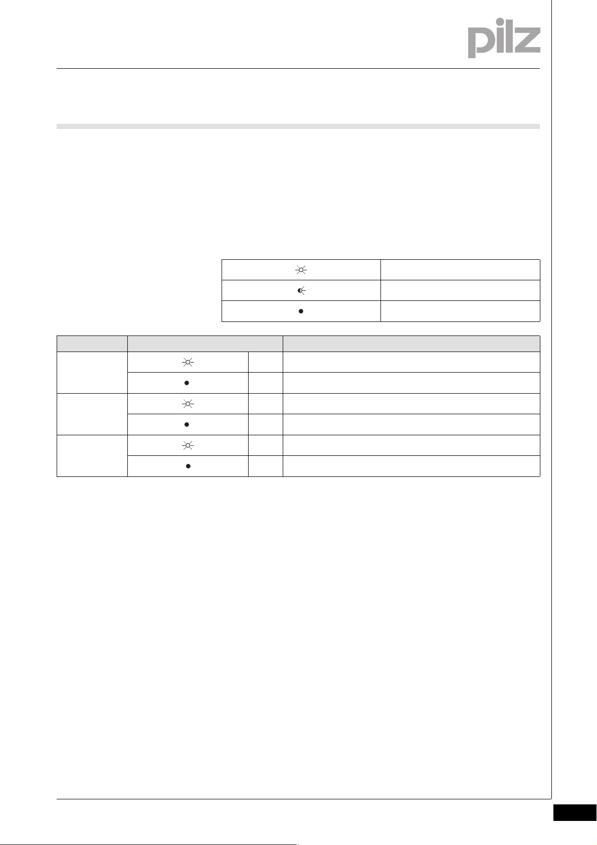
The module is ready for operation when the "Power" LED is lit continuously.
7.1.1 Display elements for device diagnostics
Display elements for device diagnostics 7-Anzeige Legende 3x
Legend:
Betrieb_Anzeige_PDP_PSE N
LED on
LED flashes
LED off
LED LED status Meaning
Power green The unit is ready for operation
The unit is not ready for operation
Diag green The actuator is within the response range
The actuator is not within the response range
Lock green Control command for magnetic guard locking available
Control command for magnetic guard locking not available
Pilz GmbH & Co. KG, Felix-Wankel-Straße 2, 73760 Ostfildern, Germany
Telephone: +49 711 3409-0, Telefax: +49 711 3409-133, E-Mail: pilz.gmbh@pilz.de
7-1
Page 28

7 Operation
7-2
Pilz GmbH & Co. KG, Felix-Wankel-Straße 2, 73760 Ostfildern, Germany
Telephone: +49 711 3409-0, Telefax: +49 711 3409-133, E-Mail: pilz.gmbh@pilz.de
Page 29
8 Technical details
8.1 Technical details
88000Technical detailsTechnical details8-8.1Technical details8100Technical details8-][Technische Daten_PDP
Technical details
Electrical data
Supply voltage UB DC 24 V
Current load capacity at UB 2.0 A
Environmental data
EMC EN 61000-4-2, EN 61000-4-3, EN 61000-4-4, EN 61000-
4-5, EN 61000-4-6, EN 61000-6-2, EN 61000-6-4
Vibration to EN 60068-2-6
Frequency 10 - 55 Hz
Amplitude 0.35 mm
Climatic suitability EN 60068-2-14, EN 60068-2-1, EN 60068-2-2
Airgap creepage in accordance with EN 60664-1
Pollution degree 2
Ambient temperature -40 - 60 °C
Storage temperature -40 - 70 °C
Shock stress
11 ms
16 ms
Climatic suitability in accordance with EN 60068-2-78 93 % r. h. at 40 °C
Condensation temporary No. 773603
Mechanical data
Protection type
Housing IP67
Terminals IP67
Housing material
Top PBT
Connection type M12 No. 773603
Stainless steel 1.4305 No. 773613
Dimensions
Height 120.0 mm
Width 60.0 mm
Depth 20.0 mm
Weight 211 g
Technische Daten_Satz No rmen
Pilz GmbH & Co. KG, Felix-Wankel-Straße 2, 73760 Ostfildern, Germany
Telephone: +49 711 3409-0, Telefax: +49 711 3409-133, E-Mail: pilz.gmbh@pilz.de
8-1
Page 30

8 Technical details
8.2 Order reference
.8.2Order reference82 00Order reference8-Bestelldaten
Order reference
Type Features Order no.
PDP67 F 4 code Decentralised passive junction 773 603
PDP67 F 4 code VA Decentralised passive junction, V2A ring nut 773 613
PDP67 Connector cs Adapter 773 610
PDP67 Connector cs VA Adapter, V4A union screw 773 612
PSEN cable M12-8sf M12-8sm 2 m 540 340
PSEN cable M12-8sf M12-8sm 5 m 540 341
PSEN cable M12-8sf M12-8sm 10 m 540 342
PSEN cable M12-8sf M12-8sm 20 m 540 343
PSEN cable M12-8sf M12-8sm 30 m 540 344
8-2
Pilz GmbH & Co. KG, Felix-Wankel-Straße 2, 73760 Ostfildern, Germany
Telephone: +49 711 3409-0, Telefax: +49 711 3409-133, E-Mail: pilz.gmbh@pilz.de
Page 31

...
1001531-EN-05, 2012-03 Printed in Germany
© Pilz GmbH & Co. KG, 2011
+49 711 3409-444
support@pilz.com
Pilz GmbH & Co. KG
Felix-Wankel-Straße 2
73760 Ostfildern, Germany
Telephone: +49 711 3409-0
Telefax: +49 711 3409-133
E-Mail: pilz.gmbh@pilz.de
Internet: www.pilz.com
Technical support
In many countries we are
represented by our subsidiaries
and sales partners.
Please refer to our homepage
for further details or contact our
headquarters.
InduraNET p
®
, Pilz
®
, PIT
®
, PMCprotego
®
, PMI
®
, PNOZ
®
, Primo
®
, PSEN
®
, PSS
®
, PVIS
®
, SafetyBUS p
®
, SafetyEYE
®
, SafetyNET p
®
, the spirit of safety
®
are registered and protected trademarks
of Pilz GmbH & Co. KG in some countries. We would point out that product features may vary from the details stated in this document, depending on the status at the time of publication and the scope
of the equipment. We accept no responsibility for the validity, accuracy and entirety of the text and graphics presented in this information. Please contact our Technical Support if you have any questions.
Contact address
 Loading...