

Page 1
User's Manual
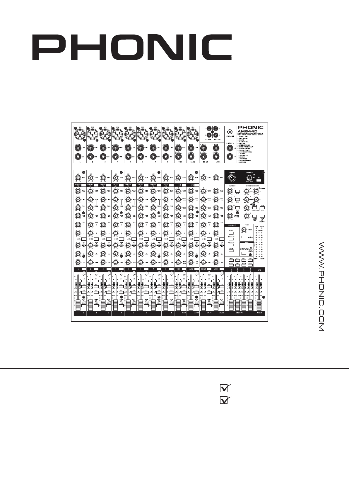
AM844D
Manual del Usuario
Page 2

English Español
AM844D
COMPACT MIXERS
MEZCLADORAS COMPACTAS
ENGLISH .....................................I
ESPAÑOL .....................................II
V1.1 05/05/2014
Page 3

USER'S MANUAL
CONTENTS
INTRODUCTION.....................................................................1
FEATURES..............................................................................1
SYSTEM REQUIREMENTS....................................................1
BASIC SETUP..........................................................................1
MAKING CONNECTIONS.......................................................2
CONTROLS AND SETTINGS..................................................4
DIGITAL EFFECT ENGINE..................................................5
SPECIFICATIONS...................................................................8
APPENDIX
DIGITAL EFFECT TABLE.........................................................1
English
APPLICATION.........................................................................2
DIMENSION.............................................................................3
BLOCK DIAGRAM...................................................................4
Phonic preserves the right to improve or alter any information within this
document without prior notice.
Page 4
IMPORTANT SAFETY INSTRUCTIONS
The apparatus shall not be exposed to dripping or splashing and that no objects
English
shall be placed on the apparatus. The MAINS plug is used as the disconnect device, the disconnect device shall
remain readily operable.
Warning: the user shall not place this apparatus in the
can be easily accessible.
1. Read these instructions before operating this
apparatus.
2. Keep these instructions for future reference.
3. Heed all warnings to ensure safe operation.
4. Follow all instructions provided in this document.
5. Do not use this apparatus near water or in locations
where condensation may occur.
6. Clean only with dry cloth. Do not use aerosol or liquid
cleaners. Unplug this apparatus before cleaning.
7. Do not block any of the ventilation openings. Install
in accordance with the manufacturer
8. Do not install near any heat sources such as radiators,
heat registers, stoves, or other apparatus (including
9. Do not defeat the safety purpose of the polarized or
grounding-type plug. A polarized plug has two blades
with one wider than the other. A grounding type plug
has two blades and a third grounding prong. The wide
blade or the third prong is provided for your safety. If
the provided plug does not
an electrician for replacement of the obsolete outlet.
’
s instructions.
.
into your outlet, consult
with liquids, such as vases,
area during the operation so that the mains switch
CAUTION
RISK OF ELECTRIC SHOCK
DO NOT OPEN
CAUTION: TO REDUCE THE RISK OF ELECTRIC SHOCK,
DO NOT REMOVE COVER (OR BACK)
NO USER SERVICEABLE PARTS INSIDE
REFER SERVICING TO QUALIFIED PERSONNEL
The lightning flash with arrowhead symbol, within an
equilateral triangle, is intended to alert the user to the
“
presence of uninsulated
product
’
magnitude to constitute a risk of electric shock to persons.
The exclamation point within an equilateral triangle is in-
tended to alert the user to the presence of important operat-
ing and maintenance (servicing) instructions in the literature
accompanying the appliance.
WARNING: To reduce the risk of or electric shock, do
not expose this apparatus to rain or moisture.
dangerous voltage” within the
10. Protect the power cord from being walked on or
pinched particularly at plug, convenience receptacles,
and the point where they exit from the apparatus.
11. Only use attachments/accessories
by the
manufacturer.
12. Use only with a cart, stand, tripod, bracket, or
table
by the manufacturer, or sold with
the apparatus. When a cart is used, use caution
when moving the cart/apparatus
combination to avoid injury from tipover.
13. Unplug this apparatus during lighting
storms or when unused for long
periods of time.
14. Refer all servicing to
service personnel.
Servicing is required when the apparatus has been
damaged in any way, such as power-supply cord or
plug is damaged, liquid has been spilled or objects
have fallen into the apparatus, the apparatus has
been exposed to rain or moisture, does not operate
normally, or has been dropped.
CAUTION: Use of controls or adjustments or performance
of procedures other than those
may result in
hazardous radiation exposure.
Page 5

INTRODUCTION
Thank you for choosing one of Phonic’s many quality compact
mixers. The brand new AM844D mixers – designed by the
ingenious engineers that have created a variety of mixers
fantastic in style and performance in the past – display similar
prociency that previous Phonic products have shown; with more
than a few renements, of course. Featuring full gain ranges,
amazingly low distortion levels, and incredibly wide dynamic
ranges, these amazing mixers are bound to make a big splash in
the World of mixing.
We know how eager you are to get started – wanting to get the
mixer out and hook it all up is probably your number one priority
right now – but before you do, we strongly urge you to take a
look through this manual. Inside, you will nd important facts and
gures on the set up, use and applications of your brand new
mixer. If you do happen to be one of the many people who atly
refuse to read user manuals, then we just urge you to at least
glance at the Instant Setup section. After glancing at or reading
through the manual (we applaud you if you do read the entire
manual), please store it in a place that is easy for you to nd,
because chances are there’s something you missed the rst time
around.
FEATURES
● Audiophile-Quality & ultra low noise
● 8 Mic/Line channels with inserts and phantom power
● 4 stereo channels with 4-band EQ
● 4 true subgroups with main L and R routing switches and
double-bused outs
● 10 mic preamps with +48V phantom power
● Direct outputs for multi-track recording
● 3-band EQ with swept mid-range plus low cut on each mono
channel
● 18dB/oct, 75Hz low cut lter on each mic channels
● 4 aux sends, aux 1 & 2 with Pre/Post switch
● 4 stereo aux returns, 2 with effect to monitor
● +4/-10 level matching on Ch9/10, Ch11/12 stereo line in for
expanded applications.
● 32/40-bit digital effect processor with 16 effects
● Control Room and Phones outputs with multi-input sources
select function
● Built-in switching power supply with universal connector,
100-240VAC, 50/60Hz
● Rack-mounting kit included
GETTING STARTED
1. Ensure all power is turned off on the AM844D Mixer. To
totally ensure this, the AC cable should not be connected to
the unit.
2. All faders and level controls should be set at the lowest
level and all channels switched off to ensure no sound is
inadvertently sent through the outputs when the device
is switched on. All levels should be altered to acceptable
degrees after the device is turned on.
3. Plug all necessary instruments and equipment into the
device’s various inputs as required. This may include line
signal devices, as well as microphones and/or guitars,
keyboards, etc.
4. Plug any necessary equipment into the device’s various
outputs. This could include Ampliers, active speakers or
monitors, signal processors, and/or recording devices. 5.
Plug the supplied AC cable into the AC inlet on the back of
the device ensuring the local voltage level is identical to that
required on your device.
6. Plug the supplied AC cable into a power outlet of a suitable
voltage.
7. Turn the power switch on.
CHANNEL SETUP
1. To ensure the correct audio levels of each input channel is
selected, every channel should rst be switched off and all
faders set to 0.
2. Choose the channel that you wish to set the level of, and
ensure that channel has a signal sent to it similar to the
signal that will be sent when in common use. For example, if
the channel is using a microphone, then you should speak or
sing at the same level the performer normally would during a
performance. If a guitar is plugged into that channel, then the
guitar should also be used as it normally would be.
3. Press the Solo button of the channel, and engage the “level
set” button next to the level meter, allowing you to see the
PFL audio signal level in the level meter.
4. Set the gain of the selected channel to a level that ensures
the audio level is around 0 dB, as indicated by the level
meter.
5. This channel is now ready to be used; you can stop making
the audio signal.
6. To activate the channel, release the Solo button and engage
the channel’s on button and press the 1/2, 3/4 or L/R routing
buttons, allowing the signal to be sent to the corresponding
destinations.
7. You should now select the next channel to set and go back to
follow steps 1 through 6.
English
AM844D
1
Page 6
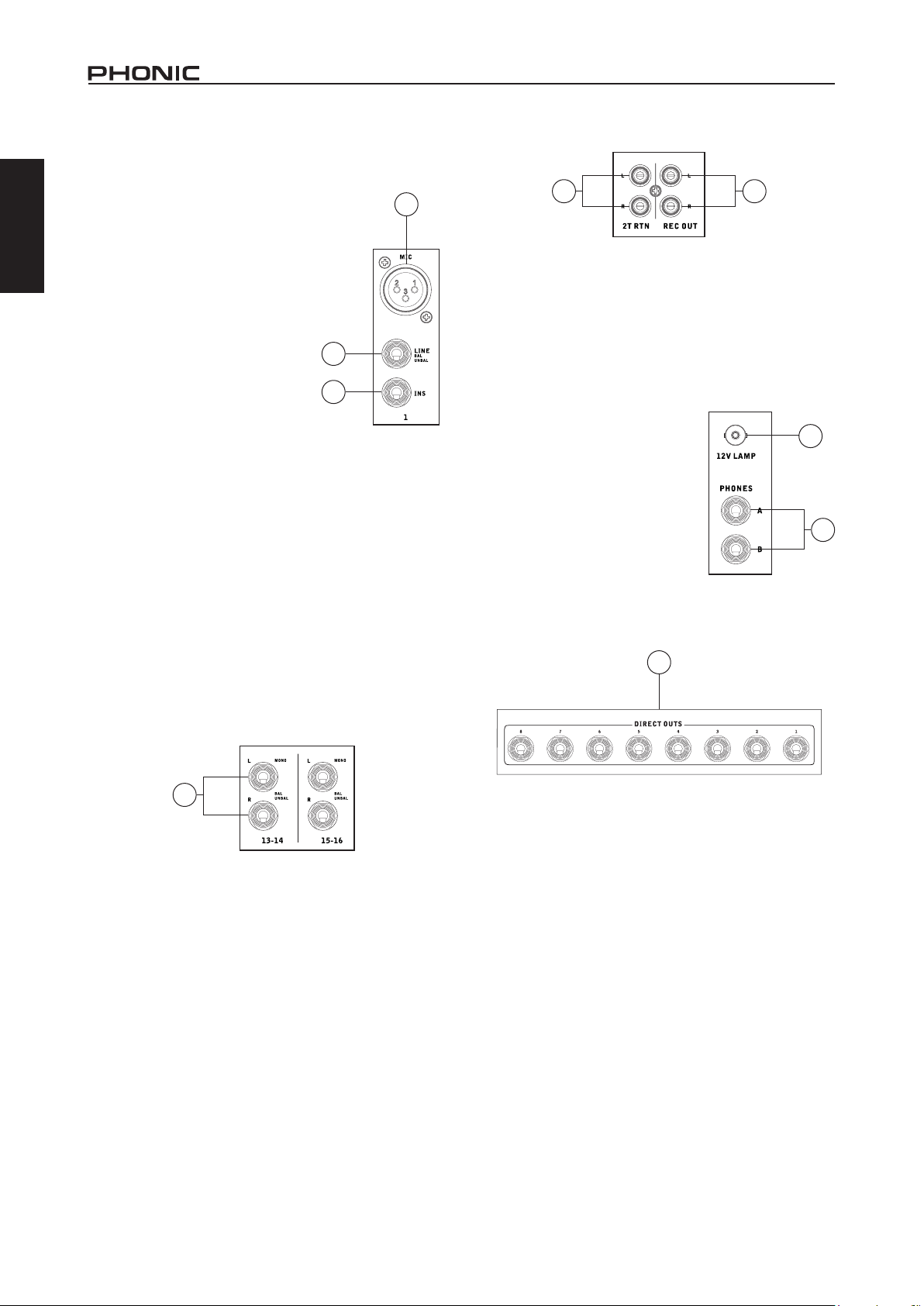
MAKING CONNECTIONS
Channel Inputs
English
1. XLR Jacks
These jacks accept XLR inputs for
balanced signals. They can be used
in conjunction with microphones such
as professional condenser, dynamic
or ribbon microphones - with standard
XLR male connectors. With low noise
preampliers, these inputs serve for
crystal clear sound replication.
NB. When using an unbalanced microphone,
please ensure phantom power is switched off.
However, when using condenser microphones
the phantom power should be activated.
2. Line In Jacks
These inputs accept 1/4” TRS and 1/4”
TS line inputs for the addition of various
music instruments – such as keyboards,
drum machines, electric guitars, as well
as a variety of other electric instruments.
3. INS (External Device Insert Jack)
The primary use for these TRS phone jacks is for the addition of
external devices, such as dynamic processors or equalizers, to
the corresponding mono input channel. This will require a Y cord
that can send and receive signals of the mixer to and from an
external processor.
4. Stereo Channel Inputs
The AM 844D features 4 stereo input channels (channels 9
through to 16), the inputs of which differ slightly to the mono
channels. The 3-pin XLR inputs on the rst two stereo inputs
are for the addition of microphones with typical XLR male inputs,
where the Line 1/4” TRS jacks are for the addition of various
stereo line level input devices, such as keyboards. If you wish
to use a monaural device on a stereo return input, simply plug
the device’s 1/4” phone jack into the left (mono) stereo input and
leave the right input bare. The signal will be duplicated to the
right due to the miracle of jack normalizing.
MASTER SECTION
5 6
1
5. 2T Return
These inputs accommodate RCA connectors from such devices
as tape and CD players, PCs and other sources. The level of this
input can just adjusted using the 2T Return control on the face
of the Mixer.
6. Record Outputs
2
3
As with the 2T Inputs, these outputs will accommodate RCA
connectors, able to be fed to a variety of recording devices.
7. Phones Outputs
These output ports are suited for
use with headphones or headphone
ampliers, allowing monitoring of the
mix. The audio level of this output is
controlled using the Control Room
/ Phones control on the front panel’s
master section.
8. 12V Lamp
This BNC socket allows you to attach
a 12 Volt gooseneck lamp, allowing
better visibility in areas with poor light.
8
7
REAR PANEL
9
4
2
9. Direct Outs
These connections are for the direct output of the signals
received by mono channels 1 through to 8, post-fader, post-EQ,
post-HPF, post-mute. They are most commonly used to connect
Multi-track recorders and they can be also used to connect your
multichannel audio to your DAW, AM 844D can also be used as
an 8-track studio mixer.
AM844D
Page 7
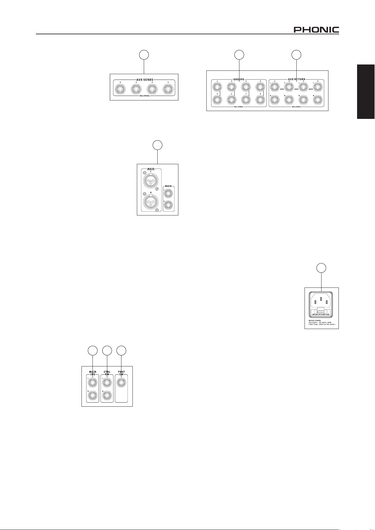
10. Auxiliary (AUX) Sends
These 1/4” phone jacks are the
nal output of line-level signal
fed from the corresponding
auxiliary send mixing buses,
and are best suited for use
with stage monitors. Feeding
the output from the Auxiliary
outs to an amplier - and
possibly an equalizer - and
then to a oor monitor speaker allows artists to monitor their
own instruments or vocals whilst performing. There are four AUX
Sends at the AM 844D.
11 Main Outputs
These outputs will output the nal stereo
line level signal sent from the main
mixing bus. The primary purpose of the
two XLR jacks is to send the main output
to external devices, which may include
power ampliers (and in-turn, a pair of
speakers), other mixers, as well as a wide
range of other possible signal processors
(equalizers, crossovers, etcetera). The two
1/4” phone jacks are able to send the Main
output to external devices that may run in
parallel with the mixer. This may include
additional power ampliers, mixers, PA
systems, as well as a wide range of other
possible signal processors.
12. Main Insert
Located on the rear of the AM 844D, the primary use for these
TRS phone jacks is for the addition of external devices, such
as dynamic processors or equalizers, to the main L and main R
signals. This will require a Y cord that can send (pre-fader) and
receive signals to and from an external processor.
13. CTRL RM Control Room Outputs
These two 1/4” Phone Jack outputs feed the signal altered by the
Control Room level control on the face of the mixer. This output
has extensive use, as it can be used to feed the signal from the
mixer to an active monitor, for the monitoring of the audio signal
from within a booth, among many other possible uses.
14. Foot Switch Jack
The foot switch port is for the inclusion of a foot switch, used for
remote activation and deactivation of the built-in Digital Effect
processor.
10
11
15 16
15. Group Outs
These 1/4” phone jacks output the nal feed from the Group 1/5,
2/6, 3/7 and 4/8 Faders on the main panel of the mixer. These
outputs can be sent to the Left or Right Main channels using the
corresponding selector, they can also be used to feed multi-track
records, as well as an amplier and speakers to be used along
with the Main Speakers. Since the signal of Group 1 is mimicked
to the Group 5 output, Group 2 to Group 6 – and so forth – these
outputs can easily be used to feed an 8 track recorder by simply
connecting the Group outputs to the corresponding Multi-track
input channels. Similar to if a Y-cord was built into your AM
844D!
16. AUX Returns
The 1/4” TRS AUX Return inputs are for the return of audio to
the AM 844D mixers, processed by an external signal processor.
If really needed, they can also be used as additional inputs. The
feed from these inputs can be adjusted using the AUX Return
controls on the face of the mixer. When connecting a monaural
device to the AUX Return 1, 2 and 4 inputs, simply plug a 1/4”
phone jack into the left (mono) input, and the signal will appear in
the right as well. You can use balanced and unbalanced signals.
NB. When any device is plugged into the mixer’s corresponding EFX
Return inputs (AUX Return 3), the mixer’s internal digital effect engine is
then disabled.
17. Power Connector and Fuse Holder
Used for the addition of a power cable and
supply, allowing power to be supplied to the
mixer. Please use the power cable that is
included with this mixer only. The Fuse holder,
located above the AC Power connector, is,
of course, for the AM 884D’s fuse. If the fuse
happens to blow, open the holder cover, and
replace the fuse with a suitable replacement
(as indicated on the fuse holder’s cover).
17
English
AM844D
12 13 14
3
Page 8

CONTROLS AND SETTINGS
Rear Panel
English
18. Power Switch
You can use it to turn the mixer on
and off. Ensure you turn all level
controls down before activating.
19. Phantom Power Switch
When this switch is in the on position,
it activates +48V of phantom power
for all microphone inputs, allowing
condenser microphones (well, the
ones that don’t use batteries) to
be used on these channels. Activating Phantom Power will be
accompanied by an illuminated LED above the left channel Level
Meter. Before turning Phantom Power on, turn all level controls
to a minimum to avoid the possibility of a ghastly popping sound
from the speakers.
NB. Phantom Power should be used in conjunction with balanced
microphones. When Phantom Power is engaged, single ended
(unbalanced) microphones and instruments should not be used on the
Mic inputs. Phantom Power will not cause damage to most dynamic
microphones, however if unsure, the microphone’s user manual should
be consulted.
Channel Controls
20. Line/Mic Gain Control
This controls the sensitivity of the input signal of
the Line/Microphone input of mono channels, the
gain should be adjusted to a level that allows the
maximum use of the audio, while still maintaining
the quality of the feed. This can be accomplished
by adjusting it to a level that will allow the peak
indicator occasionally illuminate. On channels
9-10 and 11-12, the gain control affects the
microphone input only, and on channels 13-14
and 15-16, this only affects line inputs (as there
are no microphone inputs on these channels).
21. Low Cult Filter (75 Hz)
Located on channels 1 through to 8, will activate
a high-pass lter that reduces all frequencies
below 75 Hz at 18 dB per Octave, helping to remove any
unwanted ground noise or stage rumble. Stereo channels does
not feature this low cut lter.
22. +4/-10dB Buttons
Located on stereo channels 9-10
and 11-12, these buttons select the
input signal level, allowing the mixer
to better adapt to different operating
levels. If the input source is -10 dBu
(consumer audio standard), it is best to
engage the switch, allowing the signal
to be heard. If the input source is +4
dbV (professional audio standard) the
corresponding input channel’s button
should be disengaged to ensure the
integrity of the Mixer’s circuitry. If you
are unsure of the source’s operating
level, we suggest leaving the switch
disengaged until you test the source’s signal. You can then
engage if necessary (if the level of input is obviously too low).
18
20
19
21
22
23. High Frequency Control
Use it to give a shelving boost or cut
of ±15 dB to high frequency (12 kHz)
sounds. This will adjust the amount
of treble included in the audio of
the channel, adding strength and
crispness to sounds such as guitars,
cymbals, and synthesizers.
24. Middle Frequency Control
You can provide a peaking style of
boost and cut to the level of middle
frequency sounds at a range of ±15
dB with this control. The AM 844D
mixer also provides a sweep control,
allowing you to select a center
frequency between 100 Hz and 8
kHz. Changing middle frequencies of
an audio feed can be rather difcult when used in a professional
audio mix, as it is usually more desirable to cut middle frequency
sounds rather than boost them, soothing overly harsh vocal and
instrument sounds in the audio. The stereo channels of the AM
844D mixer feature a High-Mid and Low-Mid control instead of the
typical controls described above. They provide a peaking style of
boost and cut to middle frequencies, where the frequencies are
set at 3 kHz and 800 Hz for the High- and Low-Mids respectively.
25. Low Frequency Control
This control is used to give a shelving boost or cut of ±15 dB
to low frequency (80 Hz) sounds. This will adjust the amount of
bass included in the audio of the channel, and bring more warmth
and punch to drums and bass guitars.
26. AUX Controls
These four AUX controls alters the
signal level that is being sent to
the auxiliary 1 to 4 mixing buses,
the signal of which is suitable for
connecting stage monitors, allowing
artists to listen to the music that is
being played. AUX 1 and 2 feature a
Pre/Post button, which alternates the
feed to the AUX mixing bus between
a post and pre-fader feed. AUX 3, on
the other hand, acts as an EFX send,
the signal of which can be used in
conjunction with external signal
processors (which can be returned to
the mixer via the AUX return input),
or simply as an Auxiliary output. Both
the AUX 3 (EFX) and AUX 4 controls
are post fader and are sent directly
to the corresponding outputs.
27. Pan / Balance Controls
This alternates the degree or level of
audio that the left and right side of the main mix should receive.
On mono channels, the PAN control will adjust the level that the
left and right should receive (pan), where as on a stereo channel,
adjusting the BAL control will attenuate the left or right audio
signals accordingly (balance).
23
24
25
26
27
4
AM844D
Page 9

28. On Button and Indicator
This turns the channel on, allowing the user to use the feed
from the channel’s inputs to supply the MAIN L/R, GROUP 1/2,
GROUP 3/4, AUX and EFX buses (as specied by the user, of
course). The corresponding indicator will be illuminated when
turned on.
29. 1-2, 3-4 and L-R Buttons
These handy buttons allow you to decide the audio path of the
corresponding channel. Pushing the “1/2” or “3/4” buttons allows
the signal to be sent to the Group 1/2 or 3/4 mixes respectively,
where the “L-R” allows it to be sent to the Main L/R mix.
30. Peak Indicator
This LED indicator will illuminate when the channel hits high
peaks, 6 dB before overload occurs. It is best to adjust the
channel level control so as to allow the PEAK indicator to light
up on regular intervals only. This will ensure a greater dynamic
range of audio. This indicator also doubles as a Solo indicator,
when the SOLO button is engaged.
31. Solo Button
The Solo button is pushed to allow the signal of the corresponding
channel to be sent to the Control Room / Phones mixing bus
(pre or post fader, depending on the properties selected by the
pre / post button, located by the Control Room / Phones source
buttons), for use with either headphones or studio monitors.
This button also allows for easier isolation of individual channel
signals, ensuring setting of the input gain or tracking of audio by
sound engineers is made simpler. The Peak indicator above the
Solo button also doubles as a Peak Indicator, illuminating when
the signal reaches high peaks.
32. Channel Level Control (Fader)
This control will alter the signal level that is sent from the
corresponding channel to the corresponding mixing buses.
DIGITAL EFFECT ENGINE
33
34
35
33. Program Control
This rotary control allows users to select the digital effect program
of your choice. There are 16 points on the rotary control, each of
which corresponds with an effect type. See the digital effect table
for more information.
34. Parameter Control
Turning this control will adjust the one main parameter of the
selected effect. Each effect’s parameter can be found on the
digital effect table.
35. Effect On Button
This button is pushed to turn the corresponding effect panel on
or off. Effects can also be disabled by using a footswitch with the
jack on the rear of the mixer. Please note: this button will not lock
down as similar buttons on the mixer do.
English
32
28
29
30
31
AM844D
5
Page 10

MASTER SECTION
English
36
36
41
42
37
38
40
39
36. AUX Return 1 and 2 Controls
These controls adjust the signal level of audio fed through to the
stereo AUX Return inputs. The “To AUX Send 1” and “To AUX
Send 2” controls adjust the pre-fader level of the signal from the
AUX Return controls to the corresponding AUX mixing buses for
effect-to-monitor sends.
37. EFX Return Control
This control adjusts the signal level of audio fed through to stereo
AUX Return 3 inputs. If no device is plugged into the AUX Return
3 inputs, it then acts as the nal level control of the built-in Digital
Effect Engine.
38. Main L/R - Group Buttons
The rst of these buttons changes the destination of the signal
sent from the AUX Return 3 mixing buses between the Main L/R
and Group mixing buses. The second button works when the
user selects to send the signal “To Group”, allowing the signal to
be sent to either Group 1-2 or Group 3-4.
39. AUX Return 4 Control
This control adjusts the signal level of audio fed through to the
stereo AUX Return 4 inputs. The accompanying “C-R Phones
Only” button allows users to send the signal to the Control Room
/ Phones mixing bus for monitoring purposes.
40. Solo Returns Button
Pushing this buttons allows you to send the signal from all AUX
Returns to solo mixing bus (which is, intern, send to the Control
Room / Phones mixing bus). When the Solo is activated, the
corresponding LED indicator will illuminate.
41. AUX Send Master Controls
These controls adjust the nal level of the AUX 1, 2 and 3/4
signals (as taken from the AUX 1, 2, 3 and 4 level controls on each
channel strip), the audio of which is sent to the corresponding
AUX send outputs. The SOLO buttons accompanying these
controls allow you to send the AUX send signals to the Control
Room / Phones mixing bus for monitoring purposes.
42. AUX Solo Buttons
Pushing one or more of these buttons allows you to send the
signals from the AUX 1, 2 or 3/4 mixing buses to the Control
Room / Phones mixing bus.
43. Solo Mode Button and Indicator
This button alternates the solo source signals between those of
post-fader (normal) and pre-fader feeds (level set), to be sent to
the Control Room / Phones mixing bus. When the Solo indicator,
located beside the Level Meter, is illuminated, one or more Solo
buttons has been pushed; therefore the Level meter will display
properties of the Solo signal, which is helpful with setting of
channel properties. If the Solo indicator illuminates green, this
means the Solo feed is a pre-fader signal. If the solo indicator
illuminates red, the feed is post-fader. If no Solo buttons are
activated, the Control Room / Phones selected sources (Main
L-R, Group 1-2, Group 3-4 and/or 2T Return) signal properties
are displayed by the Level Meter. In this case, the Level meter
will display the sum of the selected signals.
44. 2T Return Controls
Turning the 2T Return level control adjusts the signal level of
the feed from the 2T Return inputs. The “to Main L/R” button
that accompanies this control allows users to send the 2T return
signal to the Main L-R mixing bus. When this is done, the 2T
return signal is not sent to the Rec Out, as to avoid producing a
feedback loop when recorded signals are fed back into the 2T
return.
45
44
46
43
6
AM844D
Page 11
45. Control Room / Phones Control
This control is used to adjust the audio level of the Control Room
and Phones feeds, for use in the monitoring and tracking of
audio. The signal of the control Room / Phones mixing bus is
decided by the Source Selection buttons located immediately
below this control. If no buttons are selected, the solo signal will
be used instead.
46. Control Room / Phones Source Selection
These four buttons allow users to select the various possible
sources for the Control Room and Phones outputs. By simply
pushing one of these buttons, users have the ability to monitor
the Group 1-2, Group 3-4, Main L-R and 2T return signals, either
together or individually.
Priority Signal
High From Solo
Low Selected Source(s)
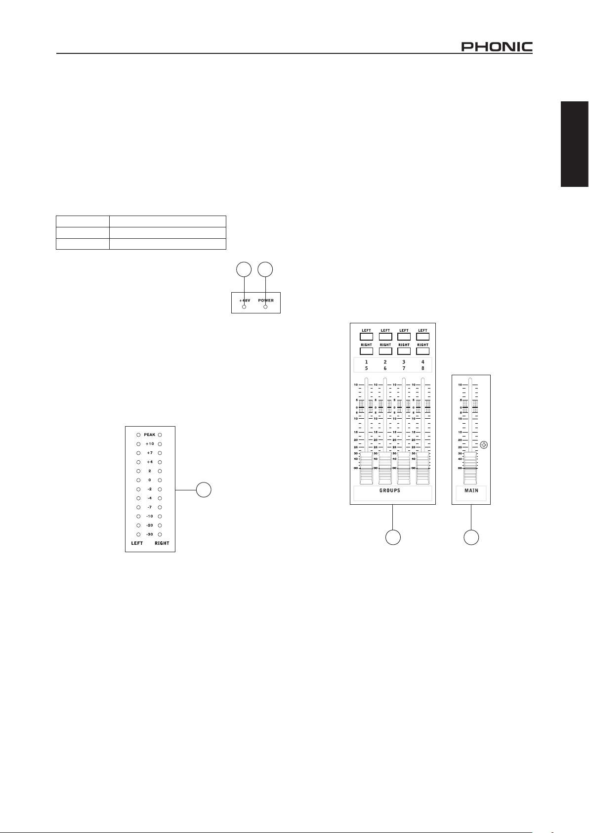
47. +48V Indicator
The internal Phantom Power will be activated
when you turn on this switch.
48. Power Indicator
The Power Indicator will light up when the power
of the mixer is on; in case you weren’t too sure.
49. Level Meter
The dual 12 segment level meter gives an accurate indication
of when audio levels of the Main L/R signal reach certain levels.
The 0 dB indicator illuminates is approximately equal to an output
level of +4 dBu (balanced), and the PEAK indicator illuminates
about 1.5 dB before the signal is dynamically clipped. To make
the maximum use of audio, set the various level controls so that
it sits steadily around 0 dB to make full use of audio, while still
maintaining fantastic clarity.
47
48
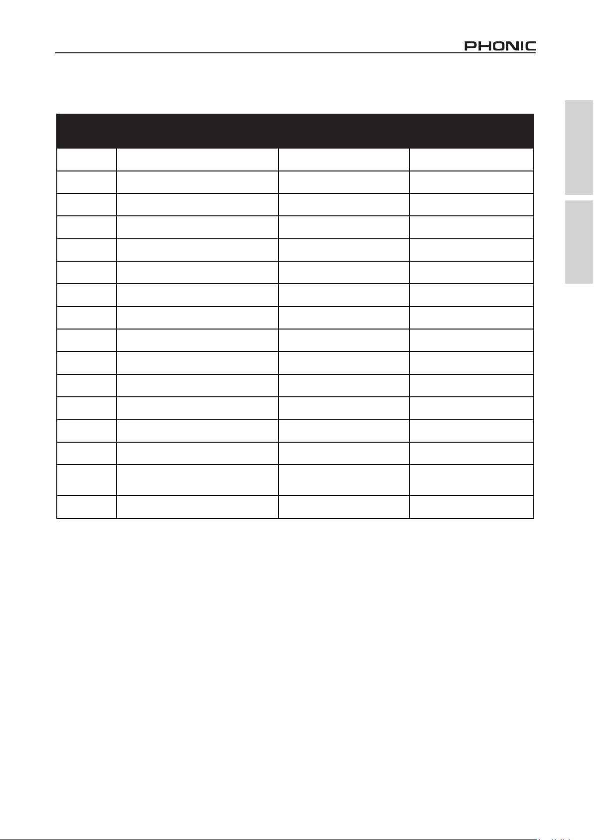
50. Group 1/5, 2/6, 3/7 and 4/8 Controls
These four faders are the nal level control for the Group 1 to 4
audio feeds (the signals of which are doubled in the 5 – 8 Group
outputs), sent to the corresponding Group outputs on the rear of
the AM844D to feed external devices such as effect processors,
and, most commonly, multi-track recorders. These faders can
be fed a signal from the various mono and stereo channels, as
well as the AUX Return 3, depending on your selections. When
pushed all the way
up, these faders provide 10 dB of gain to the signal, and, when
set all the way down, effectively mute the signal. The Group
Controls also feature individual left and right buttons, which allow
you to send the various Group signals to the Main Left and Right.
This can be handy when wanting to combine the signals from
different signals and control their input levels simultaneously,
then send them to the Main L/R signal (eg. when multiple inputs
are used for, say, drums, you can combine these inputs together
to be controlled much simpler by a single fader).
51. Main L/R Fader
The Left and Right main mix is controlled with this fader – the
nal level control for the Main Left and Right audio feeds, sent to
the Main L and R outputs. When pushed all the way up, the Main
L/R fader provides 10 dB of gain to the signal, and when set all
the way down, the signal is effectively muted.
English
49
51
50
5
51
AM844D
7
Page 12

SPECIFICATIONS
English
Inputs
Total Channels 12
Balanced Mono Mic / Line channel 8
Balanced Mic / Stereo Line channel 2
Balanced Stereo Line Channel 2
Aux Return 4 stereo
2T Input Stereo RCA
Outputs
Main L/R Stereo 2 x 1/4” TRS, Bal. & 2 x XLR
Main out with inserts Yes
Rec Out Stereo RCA
CTRL RM L/R 2 x 1/4” TS
Phones 2
Direct Out Mic/Line Ch1~ Ch8
Channel Strips 12
Aux Sends 4
Pan/Balance Control Yes
Channel Insert Ch 1 ~ Ch 8
Volume Controls 60mm fader
Master Section
Aux Send Masters 3
Master Aux Send Solo Stereo Aux Returns 3 4
Aux Return Assign to Subgroup 1
Effects Return to Monitor 2
Global AFL/PFL Solo Mode Yes
Faders 4 subgroups, Main L & R
Metering
Number of Channels 2
Segments 12
Phantom Power Supply +48V DC
Switches Master
32/40-bit Digital Effect Processor
Frequency Response (Mic input to any output)
20Hz ~ 60KHz +0/-1 dB
20Hz ~ 100KHz +0/-3 dB
16 effects with parameter control and
foot switch jack (effect on/off)
Crosstalk (1KHz @ 0dBu, 20Hz to 20KHz bandwidth, channel in to main L/R outputs)
Channel fader down, other channels at unity <-90 dB
8
AM844D
Page 13

Noise (20Hz~20KHz; measured at main output, Channels 1-4 unit gain; EQ at; all channels on main mix; channels 1/3
as far left as possible, channels 2/4 as far right as possible. Reference=+6dBu)
Master @ unity, channel fader down -86.5 dBu
Master @ unity, channel fader @ unity -84 dBu
S/N ratio, ref to +4 >90 dB
Microphone Preamp E.I.N. (150 ohms terminated,
max gain)
THD (Any output, 1KHz @ +14dBu, 20Hz to 20KHz,
channel inputs)
CMRR (1 KHz @ -60dBu, Gain at maximum) 80dB
Maximum Level
Mic Preamp Input +10dBu
All Other Input +21dBu
Balanced Output +28dBu
Impedance
Mic Preamp Input All Other Input (except insert) 2 K ohms 10 K ohms
RCA 2T Output Ch Equalization 1.1 K ohms 3-band, +/-15dB (4-band on Stereo Ch)
Low EQ 80Hz
Mid EQ (mono channel) LMid EQ (stereo channel) 100-8k Hz, sweepable 800 Hz
<-129.5 dBm
<0.005%
English
HMid EQ (stereo channel) 3 kHz
Hi EQ 12 kHz
Low cut lter 75 Hz (-18 dB/oct)
Built-in Power Supply 100-240 VAC, 50/60 Hz
Net Weight 5.9 kg (13 lbs)
Dimensions (WxHxD) 418x140x438 mm (16.5”x5.5”x17.25”)
AM844D
9
Page 14

English
SERVICE AND REPAIR
For replacement parts, service and repairs please contact the Phonic distributor in your
country. Phonic does not release service manuals to consumers, and advice users to not
attempt any self repairs, as doing so voids all warranties. You can locate a dealer near you at
http://www.phonic.com/where/.
WARRANTY INFORMATION
Phonic stands behind every product we make with a no-hassles warranty. Warranty coverage
may be extended, depending on your region. Phonic Corporation warrants this product for a
minimum of one year from the original date of purchase against defects in material and
workmanship under use as instructed by the user’s manual. Phonic, at its option, shall repair
or replace the defective unit covered by this warranty. Please retain the dated sales receipt as
evidence of the date of purchase. You will need it for any warranty service. No returns or repairs
will be accepted without a proper RMA number (return merchandise authorization). In order to
keep this warranty in effect, the product must have been handled and used as prescribed in the
instructions accompanying this warranty. Any tampering of the product or attempts of self repair
voids all warranty. This warranty does not cover any damage due to accident, misuse, abuse,
or negligence. This warranty is valid only if the product was purchased new from an authorized
Phonic dealer/distributor. For complete warranty policy information, please visit
http://www.phonic.com/warranty/.
CUSTOMER SERVICE AND TECHNICAL SUPPORT
We encourage you to visit our online help at http://www.phonic.com/support/. There you can find
answers to frequently asked questions, tech tips, driver downloads, returns instruction and other
helpful information. We make every effort to answer your questions within one business day.
support@phonic.com
http://www.phonic.com
10
AM844D
Page 15

Manual del Usuario
CONTENIDO
INTRODUCCIÓN.....................................................................1
CARACTERÍSTICAS...............................................................1
COMENZANDO..................................................1
CONFIGURACIÓN DEL CANAL..............................................1
HACER CONEXIONES ...........................................................2
CONTROL Y CONFIGURACIONES........................................4
MOTOR DE EFECTO DIGITAL........................................5
ESPECIFICACIONES............................................................8
APÉNDICE
TABLA DE EFECTO DIGITAL..................................................1
APLICACIÓN...........................................................................2
English Español
DIMENSION.............................................................................3
DIAGRAMA DE BLOQUE........................................................4
Phonic se reserva el derecho de mejorar o alterar cualquier información
provista dentro de este documento sin previo aviso.
AM844D
1
Page 16

English Español
2
AM844D
Page 17

INTRODUCCIÓN
Gracias por elegir una de las muchas mezcladoras compactas
de calidad de Phonic. Las nuevas Mezcladoras AM844D
– diseñadas por ingenieros brillantes que han creado una
variedad de fantásticas mezcladoras en estilo y funcionamiento
en el pasado – lucen capacidad similar que han demostrado
los productos de Phonic anteriormente, con un poco más de
renamiento por supuesto. Presentando rango de ganancia
completo, niveles de distorsión sorprendentemente bajos y
rangos dinámicos increíblemente amplios, estas mezcladoras
asombrosas seguramente harán un gran impacto en el mundo
de la mezcla.
Sabemos que está ansioso de comenzar –queriendo sacar
la mezcladora e instalar todo es probablemente su primer
prioridad en este momento- pero antes de hacerlo, le sugerimos
encarecidamente que eche un vistazo a este manual. En su
contenido, usted encontrará hechos importantes e ilustraciones
sobre conguración, uso y aplicaciones de su nueva mezcladora.
Si usted es una de esas personas que se rehusa rotundamente
a leer los manuales de usuario, entonces solo le pedimos que
por lo menos hojea las primeras páginas. Luego de hojear o leer
el manual (le aplaudimos si usted leyó el manual entero), por
favor guardelo en un lugar de fácil acceso ya que se le puede
haber escapado algo en la primera leída.
CARACTERÍSTICAS
● Calidad audiólo & ruido ultra bajo
● 8 canales de Mic/Línea con inserts y fuente fantasma
● 4 canales de estéreo con EQ de 4 bandas
● 4 subgrupos verdaderos con interruptores de ruteo principal
I y D y salidas de doble bus
● 10 preamplicadores mic con fuente fantasma +48V
● Salidas directas para grabación de multi-pista
● EQ de 3 bandas con barrido de rango medio más corte bajo
en cada canal mono
● 18dB/oct, 75Hz ltro de corte bajo en cada canal mic
● 4 envíos aux, aux 1 & 2 con interruptor Pre/Post
● 4 retornos aux estéreo, 2 con efecto a monitor
● Nivel +4/-10 en entrada de línea de estéreo de Canal 9/10,
Canal 11/12 para aplicaciones expandidas
● Procesador de efectos estéreo digital de 32/40-bit con 16
programas
● Salidas de Sala de Control y Audífonos con función de
selección de fuentes de multiple entrada
● Fuente de alimentación intercambiable integrada con
conector universal, 100-240VAC, 50/60Hz
● Kit de montaje en rack incluido
COMENZANDO
1. Asegúrese que toda la energía de la Mezcladora AM884D
esté apagada. Para estar completamente seguro de ésto, el
cable AC no debería estar conectado a la unidad.
2. Todos los faders y controles de nivel deberían estar
seteados en el nivel más bajo y todos los canales apagados
para asegurar que el sonido no se envíe inadvertidamente
a las salidas cuando se enciende el dispositivo. Todos los
niveles pueden ser alterados a grados aceptables una vez
encendido el dispositivo.
3. Enchufe todos los instrumentos y equipos necesarios en
las varias entradas de dispositivo. Estos podrían incluir
dispositivos de señal de línea, micrófonos y/o guitarras,
teclados, etc.
4. Enchufe todos los equipos necesarios en las varias salidas
de dispositivo. Estos podrían incluir amplicadores, altavoces
activos o monitores, procesadores de señal y/o dispositivos
de grabación.
5. Enchufe el cable AC suministrado en la entrada AC en la
parte dorsal del dispositivo asegurando que el nivel de
voltaje local es idéntico al que se requiere su dispositivo.
6. Enchufe el cable AC suministrado en una salida de energía
de voltaje compatible.
7. Encienda el interruptor de energía.
CONFIGURACIÓN DEL CANAL
1. Para asegurar que el nivel de audio de cada canal de entrada
sea correcto, cada canal debería primero estar apagado y
todos los faders seteados a 0.
2. Elija el canal que usted desea setear el nivel y, asegúrese
de que ese canal tenga una señal de envío similar a la señal
que será enviada en uso común. Por ejemplo, si el canal
está utilizando un micrófono, entonces usted debería hablar
o cantar al mismo nivel que el cantante usaría durante su
presentación. Si se conecta una guitarra en ese canal,
entonces la guitarra también debería ser tocada como es
normalmente.
3. Presione el botón Solo de canal y emplea el botón “seteo de
nivel” (level set) al lado de medidor de nivel, permitiendole
ver el nivel de señal de audio PFL en el medidor de nivel.
4. Setee la ganancia de canal seleccionado a un nivel que
asegura que el nivel de audio es alrededor de 0dB, como
indicado por el medidor de nivel.
5. Este canal está ahora listo para usarse; usted puede dejar
de hacer la señal de audio.
6. Para activar el canal, libere el botón Solo y emplea el botón
encendido de canal y presione los botones de ruteo 1/2, 3/4
o I/D, permitiendo que la señal sea enviada a los destinos
correspondientes.
7. Ahora debería seleccionar el siguiente canal para congurar
y repita los pasos de 1 a 6.
English Español
AM844D
1
Page 18

HACIENDO CONEXIONES
SECCIÓN MASTER
Entradas de Canal
English Español
1. Jacks XLR
Estos jacks aceptan entradas XLR
para señales balanceadas. Pueden ser
utilizados junto con micrófonos tales
como de condensador profesional,
dinámicos o de cinta –con conectores
machos XLR estándares. Con
preamplicadores de bajo ruido, estas
entradas sirven para reproducción de
audio limpio cristalino.
Nota: Cuando se utiliza un micrófono
desbalanceado, por favor asegure que
la Fuente Fantasma esté apagada. Sin
embargo, cuando se emplea mocrófonos de
condensador la Fuente Fantasma debería
estar activada.
2. Jacks de Entrada de Línea
Estas entradas aceptan entradas de
línea de 1/4” TRS y 1/4” TS, para
agregar varios instrumentos musicales - como teclados,
máquinas de batería, guitarras eléctricas y una variedad de otros
instrumentos eléctricos.
3. INS (Jack de Inserción de Dispositivo Externo)
El uso primario para estos jacks audífono TRS es para agregar
dispositivos externos, como procesadores dinámicos o
ecualizadores, a canal de entrada mono correspondiente. Esto
requerirá un cable Y que puede enviar y recibir señales de la
mezcladora a y desde un procesador externo.
4. Entradas de Canal de Estéreo
La AM 844D presenta 4 canales de entrada de estéreo (canales
9 a 16), cuyas entradas dieren un poco de las de canales mono.
Las entradas XLR de 3 pines en las dos primeras entradas
de estéreo son para agregar micrófonos con entradas típicas
macho XLR, donde jacks de línea 1/4” TRS son para adición
de varios dispositivos de entrada de nivel de línea, tales como
teclados. Si desea usar un dispositivo monoaural en una entrada
de retorno de estéreo, simplemente enchufe el jack audífono
1/4” de dispositivo en la entrada izquierda de estéreo (mono) y
deje la entrada derecha desenchufado. La señal se duplicará a
la derecha, debido al milagro de la normalización de jack.
2
3
1
5 6
5. Retorno 2T
Estas entradas acomodan conectores RCA desde dispositivos
como reproductores de CD y tape, PCs y otras fuentes. El nivel
de esta entrada puede ajustar utilizando el control de Retorno 2T
en la cara de la Mezcladora.
6. Salidas de Grabación
Como con las Entradas 2T, estas salidas acomodarán a los
conectores RCA, para ser alimentadas a una variedad de
dispositivos de grabación.
7. Salidas de Audífonos
Estos puertos de salida es
para utilizarse con auriculares
o amplicadores de audífonos,
permitiendo monitorear la mezcla.
El nivel de audio de esta salida es
controlado usando el control de
Control Room / Audífonos en la
sección master de panel frontal.
8. Lámpara de 12V
Este enchufe BNC le permite anexar
una lámpara de brazo, permitiendo
una mejor visibilidad en áreas con poca luz.
8
7
PANEL DE DORSO
9. Salidas Directas
Estas conexiones son para salida directa de señales recibidas
por canales mono 1 a 8, post-fader, post-EQ, post-HPF, postmute.
Son utilizados más comunmente para conectar grabadoras de
multi-pista y pueden ser utilizados también para conectar su
audio de multicanal a su DAW, la AM844D también puede ser
usada como una mezcladora de estudio de 8 pistas.
9
4
2
AM844D
Page 19

10. Envíos Auxiliares (AUX)
Estos jacks audífonos 1/4”
son salidas nales de la señal
de nivel de línea alimentada
desde correspondientes
buses auxiliares de mezcla de
envío, y son más adecuados
para usar con monitores de
escenario. Alimentando la
salida desde salidas auxiliares
a un amplicador –y posiblemente a un ecualizadory luego a un
altavoz de monitor de piso permite a los artistas a monitorear sus
propios instrumentos o vocales mientras ejecuata. Hay cuatro
Envíos AUX en AM844D.
11. Salidas Principales
Estas salidas generarán la señal nal
estéreo de nivel de línea enviada desde bus
de mezcla principal. El propósito primario
de los dos jacks XLR es el de enviar la
salida principal a dispositivos externos,
que pueden ser amplicadores de potencia
(alternadamente, un par de altavoces),
otras mezcladoras y también un rango
amplio de otros posibles procesadores de
señal (ecualizadores, crossovers, etc.). Los
dos jacks audífonos de 1/4” son capaces
de enviar la salida Principal a dispositivos
externos que pueden funcionar en paralela
con la mezcladora. Ésto podría incluir
amplicadores de potencia adicionales, mezcladoras, sistemas
PA y un rango amplio de otros posibles procesadores de señal.
12. Inserción Principal
Localizados en el dorso de AM 844D, el uso primario para estos
jacks audífono TRS es para agregar dispositivos externos, como
procesadores dinámicos o ecualizadores, a señales de principal
I y principal D. Requerirá un cable Y que puede enviar (pre-fader)
y recibir señales a y desde un procesador externo.
13. Salidas de CTRL RM Control Room (Sala de Control)
Estas dos salidas de Jack Audífono 1/4” alimenta la señal
alterada por el control de nivel de Control Room en el panel
frontal de la mezcladora. Esta salida tiene uso extensivo, como
puede ser usada para alimentar la señal desde la mezcladora a
un monitor activo, para el monitoreo de la señal de audio desde
una cabina, entre muchos otros posibles usos.
14. Jack de Interruptor de Pie
El puerto de interruptor de pie es para la inclusión de un
interruptor de pie, utilizado para la activación y desactivación
remota de procesador de Efecto Digital incorporado.
10
11
15 16
English Español
15. Salidas de Grupo
Estos jacks audífonos de 1/4” generan la alimentación nal
desde Faders de Grupo 1/5, 2/6, 3/7 y 4/8 en el panel principal
de la mezcladora. Estas salidas pueden ser enviadas a
canales Principal Izquierdo o Derecho utilizando el selector
correspondiente, también pueden ser utilizadas para alimentar
a grabaciones de multi-pista y como un amplicador y altavoces
para ser utilizados junto con los altavoces principales. Como
la señal de Grupo 1 es copiada a la salida de Grupo 5, Grupo
2 a Grupo 6 –y así sucesivamente- estas salidas pueden
fácilmente ser utilizadas para alimentar una grabadora de
8 pistas, simplemente conectando las salidas de Grupo a los
correspondientes canales de entrada multi-pista. De manera
similar si un cable Y está integrado en su AM 844D!
16. Retornos AUX
Las entradas de Retorno AUX de 1/4” TRS son para el retorno de
audio a las mezcladoras AM 844D, procesado por un procesador
de señal externo. Si realmente se necesita, pueden ser utilizadas
también como entradas adicionales. La alimentación de estas
entradas puede ser ajustada por los controles de Retorno AUX
en el panel frontal de la mezcladora. Cuando se conecta un
dispositivo monoaural a las entradas de Retorno AUX 1, 2 y 4,
simplemente enchufe un jack audífono de 1/4” en la entrada
izquierda (mono), y la señal aparecerá en la derecha también.
Usted puede utilizar señales balanceadas y desbalanceadas.
Nota. Cuando algún dispositivo está enchufado en las entradas
correspondientes de Retorno EFX de la mezcladora (Retorno AUX
3), el motor de efecto digital interno de la mezcladora es entonces
desactivado.
17. Conector de Energía y Portafusible
Utilizado para agregar un cable de energía y suministro,
permitiendo que la energía sea suministrada a la mezcladora.
Por favor utilice el cable de energía que está incluído con esta
mezcladora solamente. El portafusible, localizado arriba de
conector de Energía AC es por supuesto para el fusible de AM
884D. Si el fusible explota, abra la cubierta y reemplacelo con
otro compatible (como indicado en la cubierta de portafusible).
17
AM844D
12 13 14
3
Page 20

CONTROLES Y CONFIGURACIONES
Panel de Dorso
English Español
18. Interruptor de Energía
Se usa para encender o apagar la mezcladora. Asegúrese de
bajar todos los controles de nivel antes de la activación.
19. Interruptor de Fuente Fantasma
Cuando este interruptor está en la posición de encendido, se
activa +48V de fuente fantasma para todas las entradas de
micrófono, permitiendo que los micrófonos de condensador
(bueno, los que no utilizan baterías) sean usados en estos
canales. La activación de Fuente Fantasma será acompañada
por un LED iluminado sobre el canal izquierdo de Medidor de
Nivel. Antes de encender la Fuente Fantasma, regule todos
los controles de nivel al mínimo para evitar la posibilidad de un
sonido súbito horroroso saliendo de los altavoces.
Nota: La Fuente Fantasma debería
ser utilizada junto con los micrófonos
balanceados. Cuando se emplea la
Fuente Fantasma, los micrófonos de
simple terminación (desbalanceados) e
instrumentos no deberían ser utilizados
en entradas Mic. La Fuente Fantasma
no causará daño a la mayoría de los
micrófonos dinámicos, sin embargo, si
está inseguro debería consultar el manual
del usuario.
18
19
Controles de Canal
20. Control de Ganancia de Línea/Mic
Controla la sensibilidad de la señal de entrada de
Línea/Micrófono de los canales mono, la ganancia
debería ser ajustada a un nivel que permite el uso
máximo de audio, mientras siga manteniendo
la calidad de la alimentación. Ésto puede ser
logrado ajustandolo a un nivel que permite que el
indicador de pico se ilumine ocasionalmente. En
los canales 9-10 y 11-12, el control de ganancia
afecta solamente a las entradas de micrófono, y
en los canales 13-14 y 15-16, afecta solamente a
las entradas de línea (ya que no hay entradas de
micrófono en estos canales).
21. Filtro de Corte Bajo (75Hz)
Localizado en los canales 1 a 8, activará un ltro de paso-alto
que reduce todas las frecuencias debajo de 75Hz en 18dB
por Octava, ayudando a eliminar cualquier ruido de suelo o de
escenario no deseado. Los canales de estéreo no presentan
este ltro de corte bajo.
22. Botones +4/-10dB
Localizados en los canales de
estereo 9-10 y 11-12, estos botones
seleccionan el nivel de senal
de entrada, permitiendo que la
mezcladora adapta mejor a diferentes
niveles de operacion. Si la fuente
de entrada es -10dBu (estandar
audio de consumidor), es mejor
emplear el interruptor, permitiendo
que la senal sea escuchada. Si
la fuente de entrada es de +4dbV
(estandar audio profesional) el
boton de correspondiente canal de
entrada deberia ser soltado para
asegurar la integridad de circuito de
la mezcladora. Si usted esta inseguro de nivel de operacion de
la fuente, le sugerimos que deje el interruptor desenganchado
hasta que testee la senal de fuente. Puede engancharlo luego en
caso necesario (si el nivel de entrada es obviamente demasiado
bajo).
20
21
22
23. Control de Frecuencia Alta
Usado para dar un aumento o recorte
pendiente de ±15 dB a los sonidos
de frecuencia alta (12 kHz). Ajustara
la cantidad de agudo incluido en el
audio del canal, agregando fuerza y
claridad a sonidos como guitarras,
cimbalos y sintetizadores.
24. Control de Frecuencia Media
Usted puede proveer un estilo
de pico de aumento y recorte a
nivel de los sonidos de frecuencia
media en un rango de ±15 dB con
este control. La mezcladora AM
844D provee tambien un control de
barrido, permitiendole seleccionar
una frecuencia central entre 100 Hz
y 8 kHz. Cambiando las frecuencias medias de una alimentacion
de audio puede ser un poco dicil cuando se usa en una mezcla
de audio profesional, ya que generalmente se quiere mas
recortar los sonidos de frecuencia media mas que aumentarlos,
calmando demasiado voces asperas y sonidos de instrumentos
en el audio. Los canales de estereo de la mezcladora AM 844D
presentan un control de Alto-Medio y Bajo-Medio en lugar de los
controles tipicos descriptos anteriormente. Proveen un estilo de
pico de aumento y recorte a las frecuencias medias, donde las
frecuencias son seteadas en 3 kHz y 800 Hz para Alto-Medio y
Bajo-Medio respectivamente.
25. Control de Frecuencia Baja
Este control es usado para dar un aumento o recorte pendiente
de ±15 dB a los sonidos de frecuencia baja (80 Hz). Ajustara la
cantidad de grave incluido en el audio de canal y dando mas
calidez y fuerza a las baterias y guitarras bass.
26. Controles AUX
Estos cuatro controles alteran el
nivel de la senal que esta siendo
enviada a buses de mezcla auxiliar
1 a 4, su senal es apta para conectar
monitores de escenario, permitiendo
a los artistas a escuchar la musica
que esta siendo ejecutada. AUX 1
y 2 presentan un boton Pre/Post,
que alterna la alimentacion a bus de
mezcla AUX entre una alimentacion
post y pre-fader. Por otra parte,
AUX 3 actua como un envio EFX,
la senal de cual puede ser utilizada
junto con procesadores externos
de senal (que puede retornada a la
mezcladora via entrada de retorno
AUX), o simplemente como una
salida Auxiliar. Ambos controles AUX
3 (EFX) y AUX 4 son post fader y
enviados directamente a las salidas
correspondientes.
27. Controles de Pan/Balanceo
Alterna el grado o nivel de audio que los lados izquierdo y derecho
de la mezcla principal deberian de recibir. En los canales Mic, el
control PAN ajustara el nivel que el izquierdo y derecho deberian
de recibir (paneo). Mientras que en un canal estereo, ajustando
el control BAL atenuara las senales de audio izquierda o derecha
(balanceo).
23
24
25
26
27
4
AM844D
Page 21

28. Boton Encendido e Indicador
Este enciende el canal, permitiendo al usuario utilizar la
alimentacion desde las entradas de canal para suministrar
los buses PRINCIPAL I/D, GRUPO 1/2, GRUPO 3/4, AUX
y EFX (como especicado por el usuario, por supuesto). El
correspondiente indicador se iluminara cuando se enciende.
29. Botones 1-2, 3-4 e I-D
Estos botones practicos le permite decidir el camino de audio
de canal correspondiente. Pulsando los botones “1/2” o “3/4”
permite que la senal sea enviada a las mezclas de Grupo 1/2 o
3/4 respectivamente, mientras que “I-D” permite que sea enviada
a la mezcla Principal I/D.
30. Indicador de Pico
Este indicador LED se iluminara cuando el canal alcanza a picos
altos, 6dB antes de la sobrecarga. Es mejor ajustar el control de
nivel de canal que permite que el indicador de PICO se ilumina
en intervalos regulares solamente. Esto asegurara mayor rango
dinamico de audio. Este indicador tambien sirve como indicador
Solo cuando se emplea el boton SOLO.
31. Boton Solo
El boton Solo es pulsado para permitir que la senal de canal
correspondiente sea enviada a bus de mezcla de Control Room/
Phones (pre o post fader, dependiendo de las propiedades
seleccionadas por el boton pre/post, localizado por los botones
de fuente Control Room / Phones), para utilizar con audifonos o
monitores de estudio. Este boton tambien permite aislamiento
mas facil para senales de canal individual, asegurando que
sea mas simple la conguracion de la ganancia de entrada o
seguimiento de audio por ingenieros de sonido. El indicador de
Pico sobre el boton Solo tambien sirve como Indicador de Pico,
se ilumina cuando la senal llega a los picos altos.
32. Control de Nivel de Canal (Fader)
Este control alterara el nivel de la senal que es enviado desde
canal correspondiente a los buses de mezcla correspondientes.
MOTOR DE EFECTO DIGITAL
33
34
35
33. Control de programas
Este control giratorio permite al usuario seleccionar el programa
de efectos digitales de su elección. Hay 16 puntos en el control
rotativo cada uno de los cuales corresponde con un tipo de
efecto. Consulte la tabla de efectos digitales para obtener más
información.
34. Parámetro de control
Al girar este control ajustará el parámetro principal del efecto
seleccionado. El parámetro de cada efecto se puede encontrar
en la tabla de efectos digitales.
35. Efecto a botón
Se empuja este botón para activar el panel correspondiente
de efecto en encendido o apagado. Los efectos también se
pueden desactivar mediante el uso de un interruptor de pie
con la conexión de entrada en la parte posterior de la mesa
de mezclas. Atención: este botón no se bloqueara como otros
botones similares la parte delantera de la mezcladora.
English Español
32
28
31
30
29
37
38
37
39
41
40
AM844D
5
Page 22

SECCIÓN MASTER
English Español
36
36
37
38
40
39
36. Controles de Retorno AUX 1 y 2
Estos controles ajustan el nivel de la señal de audio alimentada
a las entradas de Retorno AUX estéreo. Los controles “A
Envío AUX 1” y “A Envío AUX 2” ajustan el nivel de pre-fader
de la señal desde los controles de Retorno AUX a los buses
correspondientes de mezcla AUX para envíos de efecto-amonitor.
37. Control de Retorno EFX
Este control ajusta el nivel de señal de audio alimentada a
las entradas de Retorno AUX 3 estéreo. Si no hay dispositivo
enchufado en las entradas de Retorno AUX 3, este control se
actúa entonces como el control de nivel nal de Motor de Efecto
Digital integrado.
38. Botones de Principal I/D - Grupo
El primero de estos botones cambia el destino de envío de
señal desde los buses de mezcla de Retorno AUX 3 entre los
buses Principal I/D y Grupo. El segundo botón trabaja cuando el
usuario selecciona enviar la señal “A Grupo”, permitiendo que la
señal sea enviada a Grupo 1-2 o Grupo 3-4.
39. Control de Retorno AUX 4
Este control ajusta el nivel de la señal de audio alimentado a las
entradas estéreo Retorno AUX 4. El botón acompañado “C-R
Audífonos Solamente” permite a los usuarios a enviar la señal
a bus de mezcla de Control Room / Phones para propósitos de
monitoreo.
40. Botón de Retornos Solo
Pulsando este botón le permite enviar la señal desde todos los
Retornos AUX a bus de mezcla solo (que es interno, envía a bus
de mezcla de Control Room / Phones). Cuando Solo es activado,
el indicador LED correspondiente se iluminará.
41
41. Controles Master de Envío AUX
Estos controles ajustan el nivel nal de las señales AUX 1, 2 y 3/4
(tomado desde los controles de nivel AUX 1, 2, 3 en cada tira de
canal), el audio de cual es enviado a las salidas correspondientes
de envío AUX. Los botones de SOLO acompañados a estos
controles le permite enviar las señales de envío AUX a bus de
mezcla Contrl Room / Phones para propósitos de monitoreo.
42. Botones Solo AUX
Pulsando uno o más de estos botones le permite enviar las
señales desde los buses de mezcla AUX 1, 2 o 3/4 a bus de
mezcla Control Room / Phones.
43. Botón Modo Solo e Indicador
Este botón alterna las señales de fuente solo entre las
alimentaciones post- fader (normal) y pre-fader (seteo de nivel),
para ser enviada a bus de mezcla de Control Room / Phones.
Cuando el indicador de Solo, localizado al lado de Medidor de
Nivel, es iluminado, uno o más botones de Solo ha sido pulsado;
por lo tanto, el medidor de nivel mostrará las propiedades de la
señal Solo, que es útil en la conguración de las propiedades
de canal. Si el indicador Solo ilumina verde, signica que la
alimentación de Solo es una señal pre-fader. Si el indicador Solo
ilumina rojo, la alimentacióm es post-fader. Si no hay ningún
botón Solo activado, las propiedades de la señal de fuentes
seleccionadas de Control Room / Phones (Pincipal I-D, Grupo
1-2, Grupo 3-4 y/o Retorno 2T) son mostradas por el Medidor de
Nivel. En este caso, el medidor de nivel mostrará la suma de las
señales seleccionadas.
44. Controles de Retorno 2T
Girando el control de nivel de Retorno 2T ajusta el nivel de señal
de la alimentación desde entradas de Retorno 2T. El botón “a
Principal I/D” que acompaña a este control permite a los usuarios
a enviar la señal de retorno 2T a bus de mezcla Principal I/D.
Cuando ésto está hecho, la señal de retorno 2T no es enviada a
la Salida Rec, para evitar producir un lazo de retroalimentación
cuando las señales grabadas son retroalimentadas en retorno
2T.
42
45
44
46
43
6
AM844D
Page 23

45. Control de Control Room / Phones
51
5
Este control es utilizado para ajustar el nivel de audio de las
alimentaciones de Control Room (Sala de Control) y Phones
(Audífonos), para utilizar en monitoreo y seguimiento de audio.
La señal de bus de mezcla de Control Room / Phones es decidida
por los botones de Selección de Fuente ubicados inmediatamente
debajo de este control. Si no hay botón seleccionado, se utilizará
la señal solo en su lugar.
46. Selección de Fuente de Control Room / Phones
Estos cuatro botones permiten a los usuarios a seleccionar
varias posibles fuentes para las salidas de Control Room y
Phones. Simplemente pulsando uno de estos botones, los
uauarios pueden monitorear las señales de Grupo 1-2, Grupo
3-4, Principal I-D y Retorno 2T, juntas o individualmente.
Prioridad Señal
Alta Desde Solo
Baja Fuente(s) Seleccionada
47. Indicador +48V
La Fuente Fantasma interna será activada
cuando usted enciende este interruptor.
48. Indicador de Energía
El Indicador de Energía se iluminará cuando la
energía de la mezcladora está encendida, por si
usted no está tan seguro.
49. Medidor de Nivel
El medidor de nivel dual de 12 segmentos brinda una
indicación precisa de cuándo los niveles de audio de la señal
PRINCIPAL I/D llegan a ciertos niveles. El indicador 0 dB
se ilumina aproximadamente igual a un nivel de salida de +4
dBu (balanceada) y, el indicador de PICO se ilumina cerca de
1.5dB antes de que la señal sea recortada dinámicamente. Para
hacer de uso máximo de audio, setee los controles de niveles
de tal manera que el medidor de nivel se sitúa constantemente
alrededor de 0 dB para hacer uso completo de audio mientras
siga manteniendo claridad fantástica.
47
48
50. Controles de Grupo 1/5, 2/6,3/7 y 4/8
Estos cuatro faders son control de nivel nal para alimentaciones
de audio de Grupo 1 a 4 (las señales de los cuales son
dobladas a las salidas de Grupo 5-8), enviado a las salidas
correspondientes de Grupo en la pate dorsal de AM844D para
alimentar dispositivos externos como procesadores de efecto
y más comunmente grabadoras de multi-pista. Estos faders
pueden ser alimentados una señal desde varios canales mono
y estéreo, también de Retorno AUX 3, dependiendo de sus
elecciones. Cuando se pulsa todo hacia arriba, estos faders
proveen 10 dB de ganancia a la señal y, cuando setea todo
hacia abajo, enmudecen efectivamente la señal. Los Controles
de Grupo también presentan botones izquierdo y derecho, que
le permite enviar varias señales de Grupo a Principal Izquierdo y
Derecho. Ésto puede ser práctico cuando se quiere combinar las
señales desde las diferentes señales y controlar sus niveles de
entrada simultáneamente, luego enviarlas a señal Principal I/D
(ej. cuando las entradas multiples son utilizadas para, digamos,
baterías, usted puede combinar estas entradas juntas para ser
controladas mucho más simple por un fader simple).
51. Fader Principal I/D
La mezcla principal Izquierda y Derecha es controlada con este
fader –el control de nivel nal para alimentaciones de audio
Principal Izquierdo y Derecho, enviado a las salidas de Principal
I y D. Cuando está pulsado todo hacia arriba, los faders Principal
I/D proveen 10dB de ganancia a la señal y, cuando está seteado
todo hacia abajo, la señal es silenciada efectivamente.
English Español
AM844D
49
50
51
7
Page 24

ESPECIFICACIONES
English Español
Entradad
Total de Canales 12
Balanceado Mono Mic / Línea Canal 8
Balanceado Mic / Estéreo Línea Canal 2
Balanceado Estéreo Línea Canal 2
AUX Retorno 4 estéreo
2T Entradas Mini estéreo y estéreo RCA
Salidas
Estéreo Principal I/D 2 x 1/4” TRS, Bal. & 2 x XLR
Salida Principal con inserciones Sí
Salida Rec Estéreo RCA
CTRL RM I/D 2 x 1/4” TS
Audífonos 2
Salida Directa Mic/Línea Canal 1~ Canal 8
Tiras de Canal 12
Envíos Aux 4
Control Pan/Balanceado SI
Inserción de Canal Canal 1 a Canal 8
Control de Volumen 60mm deslizador
Sección Master
Envío Aux Masters 3
Envío Aux Master Solo 3
Retornos Aux Estéreo 4
Retorno Aux Asignado a Subgrupo 1
Retorno de Efectos a Monitor 2
Modo Global AFL/PFL Solo SI
Faders 4 subgrupos, Principal I & D
Medición
Número de Canales 2
Segmentos 12
Suministro de Potencia Fantasma +48V DC
Interruptores Master
Procesador de Efecto Digital de 32/40 bits 16 programas
8
AM844D
Page 25

Respuesta en Frecuencia (entradaMic a cualquier salida)
20Hz ~ 60KHz +0/-1 dB
20Hz ~ 100KHz +0/-3 dB
Diafonía (1KHz @ 0dBu, 20Hz to 20KHz ancho de banda, canal a salida de central I/D)
Canal delizador abajo, otros canales en la unidad <-90 dB
Ruido (20Hz~20KHz; medido en salida central, Canales 1-4 unidad de ganancia; EQ plano; todo los canales en fusión central; canales 1/3 todo izquierdo posible, canales 2/4 todo derecho posible. Referencia=+6dBu)
Master @ unidad, canales deslizado abajo -86.5 dBu
Master @ unidad, canal deslizado @ unidad -84 dBu
S/N relación, ref. a +4 >90 dB
Microfono Preamp E.I.N. (150 ohms determinado, ganacia
máxima)
THD (Cualquier salida, 1KHz @ +14dBu, 20Hz a 20KHz, entra-
das de canales)
CMRR (1 KHz @ -60dBu, Ganacia al Máximo) 80dB
Nivel Máximo
Entrada de Mic Preamp +10dBu
Todo las otras Entradas +22dBu
Salidas Balanceadas +28dBu
<-129.5 dBm
<0.005%
English Español
Impedancia
Entrada Mic Preamp 2 K ohms
Todas las otras Entradas (excluyendo inserción) 10 K ohms
Salida RCA 2T 1.1 K ohms
Equalización 3-band, +/-15dB
Bajo EQ 80Hz
Medio EQ 100-8k Hz,barrible
Medio-bajo EQ 800 Hz
Medio-alto EQ 3 kHz
Alto EQ 12 kHz
Filtro de Paso Alto (Low Cut) 75 Hz (-18 dB/oct)
Requistos de Fuente 100-240 VAC, 50/60 Hz
Peso 5.9 kg (13 lbs)
Dimensiones (AnxAltxD) 418 x 140 x 438 mm (16.5” x 5.5” x 17.25”)
AM844D
9
Page 26

English Español
SERVICIO Y REPARACIÓN
Para refacciones de reemplazo y reparaciones, por favor póngase en contacto con nuestro
distribuidor de Phonic en su país. Phonic no distribuye manuales de servicio directamente a los
consumidores y, avisa a los usuarios que no intenten hacer cualquier reparación por si mismo,
haciendo ésto invalidará todas las garantías del equipo. Puede encontrar un distribuidor cerca
de usted en http://www.phonic.com/where/.
INFORMACIÓN DE LA GARANTIA
Phonic respalda cada producto que hacemos con una garantía sin enredo. La cobertura de
garantía podría ser ampliada dependiendo de su región. Phonic Corporation garantiza este
producto por un mínimo de un año desde la fecha original de su compra, contra defectos en
materiales y mano de obra bajo el uso que se instruya en el manual del usuario. Phonic, a su
propia opinión, reparará o cambiará la unidad defectuosa que se encuentra dentro de esta
garantía. Por favor, guarde los recibos de venta con la fecha de compra como evidencia de la
fecha de compra. Va a necesitar este comprobante para cualquier servicio de garantía. No se
aceptarán reparaciones o devoluciones sin un número RMA apropiado (return merchandise
autorization). En orden de tener esta garantía válida, el producto deberá de haber sido
manejado y utilizado como se describe en las instrucciones que acompañan esta garantía.
Cualquier atentado hacia el producto o cualquier intento de repararlo por usted mismo,
cancelará completamente esta garantía. Esta garantía no cubre daños ocasionados por
accidentes, mal uso, abuso o negligencia. Esta garantía es válida solamente si el producto fue
comprado nuevo de un representante/distribuidor autorizado de Phonic. Para la información
completa acerca de la política de garantía, por favor visite http://www.phonic.com/warranty/.
SERVICIO AL CLIENTE Y SOPORTE TÉCNICO
Le invitamos a que visite nuestro sistema de ayuda en línea en www.phonic.com/support/. Ahí
podrá encontrar respuestas a las preguntas más frecuentes, consejos técnicos, descarga de
drivers, instrucciones de devolución de equipos y más información de mucho interés. Nosotros
haremos todo el esfuerzo para contestar sus preguntas lo antes posible.
support@phonic.com
http://www.phonic.com
Page 27
DIGITAL EFFECT TABLE TABLA DE EFECTO DIGITAL
Appendix Apéndice
Program
Number
1 Small Hall Reverb Time (S) 0.3 to 1.1
2 Mid Room Reverb Time (S) 0.1 to 0.45
3 Plate Reverb Time (S) 0.9 to 1.45
4 Cathedral Reverb Time (S) 1.1 to 3.8
5 Mid Hall Reverb Time (S) 0.5 to 1.66
6 Jazz Lounge Reverb Time (S) 0.15 to 0.9
7 Ping Pong Delay Delay Average (S) 0.08 to 0.55
8 Short Delay Delay Average (S) 0.05 to 0.4
9 Vocal Plate Reverb Time (S) 0.2 to 2.2
10 Concert Hall Reverb Time (S) 0.3 to 2.45
11 Stage Reverb Time (S) 0.6 to 1.6
12 Doubler Feedback Ratio 20% to 90%
Program
Name
Parameter
Parameter
Range
13 Echo Delay Average (S) 0.12~0.55
14 Chorus LFO 0.66~9.6
15 Chorus + Rev
16 Spring LFO 0.16 to 1.33
Reverb Time (S)
LFO
0.8 to 8.8
0.4 to 0.8
AM844D
1
Page 28

Appendix Apéndice
COMPRESOR / LIMI
APPLICATION
There are potentially hundreds of ways to connect instruments and devices to the AM Mixers. It is advisable that you explore the functions
and nd the best setup possible for your needs, which may depend on what instruments you wish to connect, as well as how many external
devices you wish to connect and your required monitoring applications. Combining the use of different instruments with the mixer’s special
functions will ensure that your audio sounds exactly the way you want it.
APLICACIÓN
Existen cientos de maneras posibles de conectar instrumentos y dispositivos a las Mezcladoras AM. Se recomienda que explore las
funciones y encuentre la mejor conguración posible para sus necesidades, que dependerá de qué instrumentos y cuántos dispositovos
externos se quiere conectar y sus aplicaciones de monitoreo requeridas. Combinando el uso de diferentes instrumentos con las funciones especiales de la mezcladora asegurará que su audio se escucha exactamente como usted quiere.
IZQUIERD O DERECH O
AMPLIFICADO R
AMPLIFICADO R
Ꮊে
(RELLENO LA TERAL)
MICRÓFONO S
FOH AL TAV OCES
PA AL TA VOCE S
EQ
MONIT ORES
ACTIVOS
REPRODUCT OR
INTERRUP TO R
DE PEDAL
DE CD
COMPRESO R
GRABADORA DE DA T
COMPU TA DORA PO RT ÁTIL
MÁQUIN A DE BA TERÍ A
COMPRESOR / LIMI TA DO R
EFEC TO S DE
TA DO R
GUIT ARRA
GUIT ARR A
GUIT ARR A BASS
TECLADO
2
AU D Í FONO S
AM844D
Page 29

DIMENSION DIMENSION
Appendix Apéndice
AM844D
All measurements are shown in mm/inches.
Todas las medidas están mostradas en mm/pulgadas.
3
Page 30

Appendix Apéndice
BLOCK DIAGRAM DIAGRAMA DE BLOQUE
PSD
MARGORP
16
PARAMETER
4
AM844D
Page 31

MEMO
Appendix Apéndice
AM844D
5
Page 32

 Loading...