

Page 1
LIGHTOLIIÈR*
Lighting Systems
MMB & MFB
Page 1 of 2 Multi-Lyte Direct/Indirect 2-Light T8 or T5
2
Ordering Information
Type Style No.of
Lamps
Length Ballast
Type
Lamp
Type
Voltage
Type
M B
F
M
= Multi-Lyte
system
= LightlngFIxture
for individual
mounting
M
= Lighting module
for channel
attachment
2
Specifications
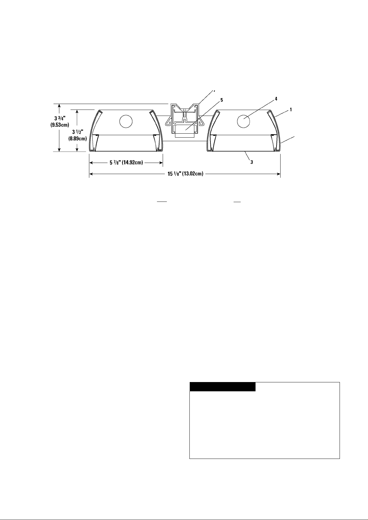
1. Housing: 20 gauge die-formed steel. Finish is white baked enamel.
2. End Plate: Die-formed 20 gauge steel spot-welded to the housing. Finished to
match housing.
3. Parabolic Louver: Low iridescent semi-specular anodized aluminum, 37°
shielding lengthwise, blades are 1-1/4" (3.18cm) high and 2" (5.08cm) O.C.
Concealed spring clips retain louver in housing.
4. Lamps: 17or32 watt T-8 fluorescent or 14,28 or 54 watt T-5 linearfluorescent.
All lamps provided by others.
5. Ballast: T8: Pre-Heat Rapid Start with a ballast factor .87. All ballasts have
a Total Harmonic Distortion (THD) <10% and are available in120 or277 volt.
Dimming is available with a dimming range of 15% to 100% in 120v only. T5:
All ballasts have "end of life" circuit protection, a Total Harmonic Distortion
(THD) <10%, a ballast factor of .87 and are available in 120 or 277 volt. Factory
installed ballast disconnect allows the ballast to be disconnected from and
reconnected to incoming power under load without turning the entire circuit off.
6. Suspension: (not shown) The Multi-Lyte Channel and the Fixture are suspended
from the ceilingby stem or aircraft cable. The stem set is finished to match the
housing and contains a 1/2" (1.27cm) diameter steel stem which can be cut
to length at the job and a 4-1/2" (11.43cm) diameter canopy. Attached to the
stem at the ceiling end is a self-aligning swivel that provides adjustment up to
38°. The cable set contains a 1/16" (0.16cm) diameter stainless steel aircraft
cable and a 1-1/2" (3.81cm) diameter or4-1/2" (11.43cm) diametercanopy. The
cable is adjustable from 6" (15.24cm) to 36" (91.44cm) with a Grip-Lock cable
adjustment. Fixtures are mounted directlyto the ceiling with independent stems
or aircraft cables and cord.
7. Module Mounting: Modules are mounted to the Multi-Lyte Channel by means
of slide clips. They are energized by insulation-displacement couplings to the
Channel's through-wiring system.
E
2
= 2-foot
nominal
4
= 4-foot
nominal
8. Fixture Mounting: (not shown) The individual Fixture mounting points are
= Electronic
D
= Dimming(120v
T8 0nly)
4
= 2-foot14W T5
5
= 4-foot28WT5
6
= 4-foot54WT8
7
= 2-foot17WT8
8
= 4-foot32WT8
1
= 120v
2
= 277v
located 30" (76.20cm) and 60" (152.40cm) centers. Referto the backfor more
information.
Performance
Efficiency: 83.6%
Distribution: 58% Indirect 42% Direct
Labels
UL, cULandIBEW.
Warranty
Multi-Lyte Complete system is covered by Lightolierthree-year limited warranty.
The electronic ballast is covered by ballast manufacturer's limited warranty.
Job Information
Job Name:
Cat. No.:
Lamp(s):
Notes:
1 Type:
Lightolier is a Philips group brand
631 Airport Road, Eall River, MA 02720 • (508) 679-8131 • Eax (508) 674-4710
We reserve the right to change details of design, materials and finish.
www.lightolier.com © 2008 Philips Group • C1008
PHILIPS
Page 2

LIGHTOLIIËR*
Lighting Systems
MMB & MFB
Page 2of 2
Performance
Report Number
: LRL797-3C
Lamps
: 2-F32T8/TL80
Suspension Mounting Detail
Lumens
125
115
90
: 3050
IES Spacing Criterion
90 70
50 3010 50 3010
0
96 96 96 80 80 80 66 66 66 53 53 53 40 40 40 35
105 1
85 82 79 71 69 67 59 57 56 48 47 46 37 37 36 31
2
76 70 66 64 60 57 53 51 48 44 42 40 34 33 32 28
95 3
67 61 56 57 53 49 48 45 42 40 37 36 32 30 29 26
60 53 48 51 46 42 43 40 37 36 33 31 29 27 26 23
85 ^
5
54 47 41 46 41 37 39 35 32 32 29 27 26 24 23 20
75 6
48 41 36 41 36 32 35 31 28 29 26 24 24 22 20 18
7
43 36 31 37 32 28 31 27 24 26 23 21 21 19 18 15
65 8
39 32 27 33 28 24 28 24 21 24 20 18 19 17 15 13
9
35 28 24 30 25 21 26 21 18 21 1816 17 15 13 12
31 24 20 26 21 18 22 18 15 19 15 13 15 13 11 9
55 10
:5
-Max S/MH
:PARA:5,PERP:5
% Effective Ceiling
Cavity Reflectance
%WallRef
50 30 10
50 1 30 10
ectance
50 3010 50 30 10 0
BF
= 1.0
Multi-Lyte Direct/Indirect 2-Light T8 or T5
Candle Power Summary
Zone 0 22 45 67 90
0
Deg. Candelas
180 738 738 738 738 738
175 740 744 745 756 754
165 728 752 783 819 840
155 669 724 789 846 856
145 594 684 772 816 825
135 474 589 656 727 754
125 380 498 600 720 767
115 238 350 532 602 601
105 127 258 320 300 290
95 33 67 51 47 44
90 0 4 8 8 10
85 2 3 4 6 6
75 6 9 11 14 13
65 24 33 49 79 66
55 85 179 356 531 592
45 307 542 758 888 919
35 488 640 889 1172 1226
25 585 644 766 991 1041
15 657 674 704 762 789
5 677 682 682 679 686
0 678 678 678 678 678
Zonal Lumens and Percentages
Zone .umens % Barelamps % Luminaires
0-90 2128 84.8 41.6
90-180 2976 48.8 58.4
0-180 5099 88.6 100.0
Footcandles
Channel Luminaire Luminaire
Spacing
Footcandles are average, initial, include a
ballast factor of 0.87 and are at a work plane
height of 30" above fhefloor.The luminaires are
suspended 8' above fhefloorin a 50'x70' room
(ceiling height is 8' plus luminaire suspension.)
Room reflectances are: 80% ceiling, 50% walls
and20%floor.
Spacing
O.C.
O' O' 112 111
8' O' 84 83
10 6' 67 66
Suspension
O.C.
5' 167 166
8' 84 83
5' 100 99
8' 63 02
5' 80 79
8' 50 50
18" 24"
Module Dimensions Detail
25-5/8‘
K|65.09cm|-H
1
18-7/16'
|46.83cm|
Fixture Mounting Detail
16'(40.64cm)
K 25-l/2'^
|64.77cm|
Lightolier is a Philips group brand
- 49-5/8'|126.05cm| -
\<
-- -- --
41-13/16'
-- - -- - - - -
|196.29cm|
t^39'|76.29cm|-
-49-l/2'|125.73cm|-
*\
Job Information Type:
631 Airport Road, Fall River, MA 02720 • (508) 679-8131 • Fax (508) 674-4710
We reserve the right to change details of design, materials and finish.
www.lightolier.com © 2008 Philips Group • C1008
PHILIPS
 Loading...