

Philips MCB-275 Service Manual
Micro System
MCB275/05
TABLE OF CONTENTS
Page
Location of PC Boards & Versions Variation ........................1-2
Specifi cations .......................................................................1-3
Measurement Setup .............................................................1-4
Service Aids, Safety Instruction, etc .....................................1-5
CD Playability Check ..................................................1-6 to 1-8
Disassembly Instructions & Service positions .........................2
Service Test Program ...........................................................3-1
Set Block Diagram ................................................................4-1
Set Wiring Diagram ..............................................................5-1
Main Board ..............................................................................6
Key & LCD Board ....................................................................7
CD & MCU Board ....................................................................8
Mechanical Exploded View & Parts List ..................................9
Revision list ...........................................................................10
©
Copyright 2009 Philips Consumer Electronics B.V. Eindhoven, The Netherlands
All rights reserved. No part of this publication may be reproduced, stored in a retrieval system or
transmitted, in any form or by any means, electronic, mechanical, photocopying, or otherwise without
the prior permission of Philips.
Published by SL0913 Service Audio Printed in The Netherlands Subject to modifi cati
Version 1.4
CLASS 1
LASER PRODUCT
GB
3141 785 31774
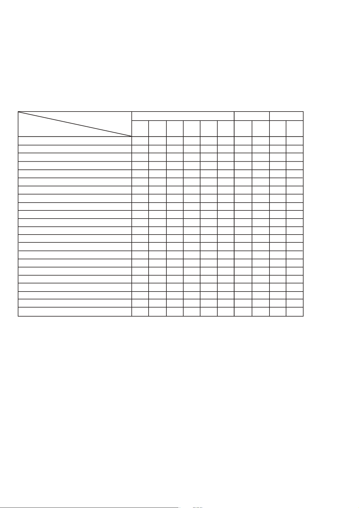
VERSION VARIATIONS
VERSION VARIATIONS:
Type /Versions: MCB275
Features &
Board in used:
Line Out
Video Out
Surround Out
Subwoofer Out
Power Booster Out
Digital Out
Digital in
Matrix Surround
Dolby Pro Logic (DPL)
Incredible Surround
Karaoke Features
Voltage Selector
ECO Power Standby (LCD Display Off) x
ECO6 Tuner Board - Systems Non-Cenelec
ECO6 Tuner Board - Systems Cenelec
USB Direct
1-2
/05
xni RDC / ni xuA
xSDR
xsweN
x
x

SPECIFICATIONS
GENERAL:
Mains voltage : 127/240V -15%+10% Switchable for /98
120V ± 10% for /37
230V ± 10% for /05/12
Mains frequency : 50/60Hz
Clock accuracy : < 4 seconds per day
Dimension centre unit :194(W)x269(H)x90(D) (mm)
1-3
Dynamic Bass Boost (DBB) : ON / OFF
Input sensitivity
Aux in (at 1kHz) : 500mV at 600 Ω
USB : Host
Output sensitivity
Headphone output at 32 Ω : 10mW ± 2dB (Max. vol.)
Power consumption
Active : 20W
Standby : < 5.5W (DEMO mode)
ECO Power Standby : < 0.5W for /05/12/37
TUNER:
FM
Tuning range : 87.5-108MHz
Grid : 50kHz for /98/12/05
100kHz for /98/55/37
IF frequency : 10.7MHz ± 20kHz
Aerial input : 75 Ω coaxial /05/12/98
300 Ω for /37
Sensitivity at 26dB S/N : < 22µf
Selectivity at 300kHz bandwidth : > 25dB
Image rejection : > 25dB [> 75dB]
IF rejection : > 60B [> 80dB]
Distortion at RF=1mV, dev. 75kHz : < 3%
-3dB Limiting point : < 23.5dBf
Crosstalk at RF=1mV, dev. 40kHz : > 18dB
COMPACT DISC:
Frequency response within ± 3dB : 125Hz - 16kHz
Output level (in Vrms) : 500mV, Z
= 100Ω
out
Signal/Noise ratio (unw.) : > 65dB
Signal/Noise ratio (A-weighted) : > 76dB
Distortion at 1kHz : < 0.02%
Channel unbalance (-40dB) : < ±2dB
Channel separation at 1kHz : > 30dB
Emphasis : 15/50 µS (switched
automatically by CD10)
THD Noise(1kHz,500mW) : < 1.0%
Volume attenuation(1kHz) : > 60dB
MP3 CD WMA:
MP3 : MPEG 1 (ISO/IEC 11172-3)
Layer3
MP3-CD Bit Rate : 8-320 kbps
WMA-CD Bit Rate
: 64-192 kbps
Sampling Rate : 8, 11.025, 12, 16, 22.05,
24, 32, 44.1, 48 kHz
Format
: ISO9660, Joliet,UDF
ID3 : V1 tag/V2 2.0/V2 3.0
Language Support : English
MW
Tuning range : 531-1602kHz for /05/12/55/98
530-1700kHz for /37/98
Grid : 9kHz for /05/12/55/98
10kHz for /37/98
IF frequency : 450kHz ± 1kHz
Aerial input : Frame aerial 18.1µH
Sensitivity at 26dB S/N : < 4.4mV/M
Selectivity at 300kHz bandwidth : > 18dB
IF rejection : > 45dB
Image rejection : > 28dB
Distortion at RF=50mV, M=80% : < 5%
AMPLIFIER:
Output power
L & R : 2 x 5.0W (4Ω, 1kHz, 10% THD)
:2 x 4.5W (4Ω, 1kHz, 10% THD) /98
:2 x 4.5W (FTC Power, 4Ω, 1kHz, 10% THD
63Hz-12.5kHz) /37
Frequency response within -3dB : 50Hz-16kHz
Digital Sound Control (DSC) : Jazz / Rock / Pop / Classic
[....] Values indicated are for /05/12 only.
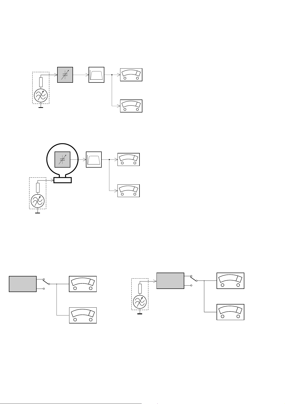
MEASUREMENT SETUP
Tuner FM
1-4
Bandpass
LF Voltmeter
e.g. PM2534
RF Generator
e.g. PM5326
DUT
250Hz-15kHz
e.g. 7122 707 48001
Ri=50Ω
S/N and distortion meter
e.g. Sound Technology ST1700B
Use a bandpass filter to eliminate hum (50Hz, 100Hz) and disturbance from the pilottone (19kHz, 38kHz).
Tuner AM (MW,LW)
RF Generator
e.g. PM5326
Ri=50Ω
DUT
Frame aerial
e.g. 7122 707 89001
Bandpass
250Hz-15kHz
e.g. 7122 707 48001
LF Voltmeter
e.g. PM2534
S/N and distortion meter
e.g. Sound Technology ST1700B
To avoid atmospheric interference all AM-measurements have to be carried out in a Faraday´s cage.
Use a bandpass filter (or at least a high pass filter with 250Hz) to eliminate hum (50Hz, 100Hz).
CD
Use Audio Signal Disc
(replaces test disc 3)
DUT
L
R
SBC429 4822 397 30184
S/N and distortion meter
e.g. Sound Technology ST1700B
LEVEL METER
e.g. Sennheiser UPM550
with FF-filter
Recorder
Use Universal Test Cassette CrO2 SBC419 4822 397 30069
or Universal Test Cassette
LF Generator
e.g. PM5110
Fe SBC420 4822 397 30071
DUT
L
R
S/N and distortion mete
e.g. Sound Technology ST1700B
LEVEL METER
e.g. Sennheiser UPM550
with FF-filter
SERVICE AIDS
1-5
Service Tools:
Universal Torx driver holder .................................4822 395 91019
Torx bit T10 150mm ...........................................4822 395 50456
Torx driver set T6-T20 .........................................4822 395 50145
Torx driver T10 extended .....................................4822 395 50423
GB
All ICs and many other semi-conductors are
susceptible to electrostatic discharges (ESD).
Careless handling during repair can reduce life
drastically.
When repairing, make sure that you are
connected with the same potential as the mass
of the set via a wrist wrap with resistance.
Keep components and tools also at this
potential.
WARNING
GB
Safety regulations require that the set be restored to its original
condition and that parts which are identical with those specified,
be used
Safety components are marked by the symbol
!
.
Compact Disc:
SBC426/426A Test disc 5 + 5A ...........................4822 397 30096
SBC442 Audio Burn-in test disc 1kHz .................4822 397 30155
SBC429 Audio Signals disc .................................4822 397 30184
Dolby Pro-logic Test Disc ....................................4822 395 10216
ESD
CLASS 1
LASER PRODUCT
Lead free
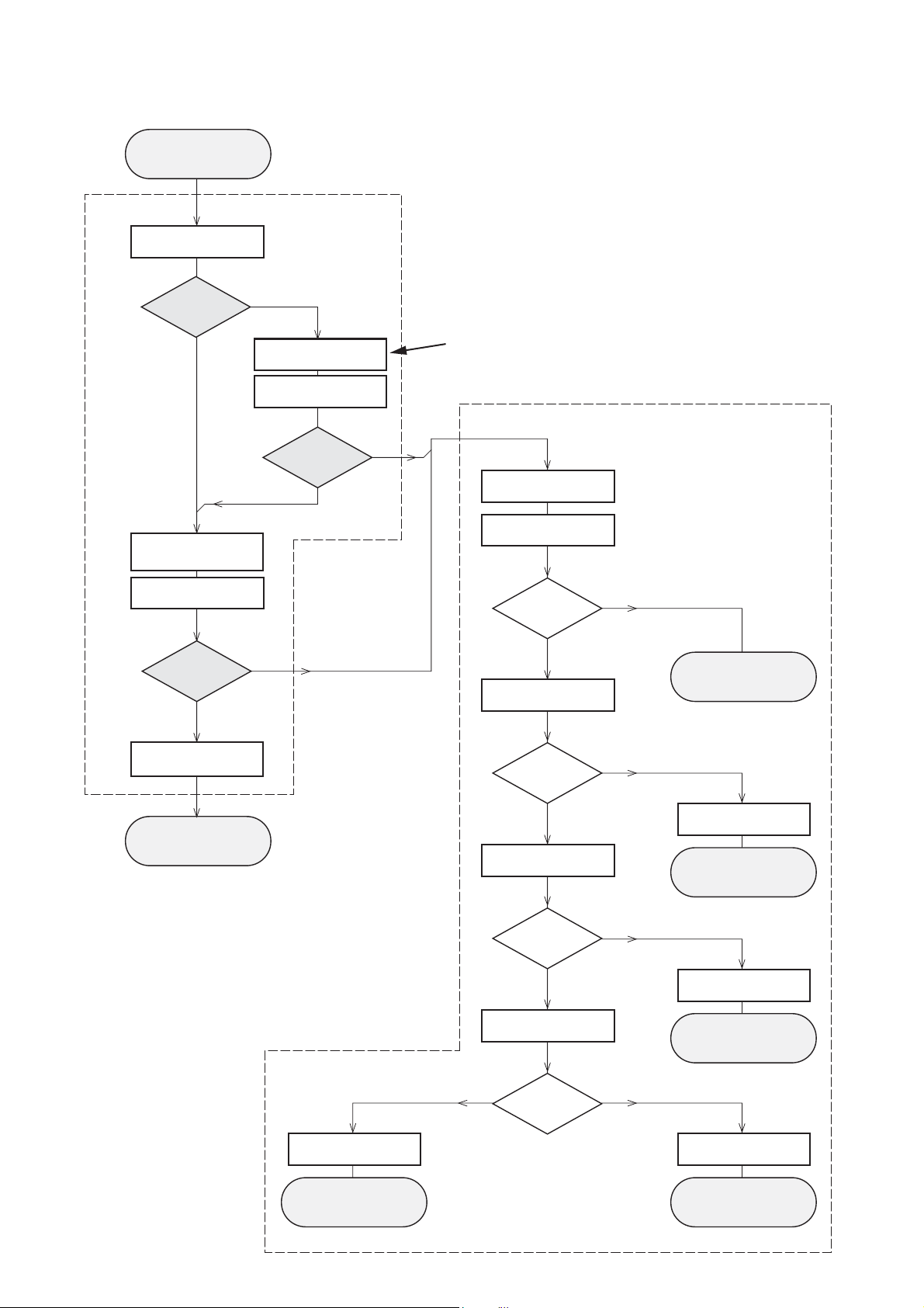
CD PLAYABILITY CHECK
Customer complaint
"CD related problem"
check playability
1-6
Set remains closed!
1
playability
ok ?
Y
Play a CD
for at least 10 minutes
check playability
playability
ok ?
Y
N
"fast" lens cleaning
check playability
playability
ok ?
N
3
For flap loaders (= access to CD drive possible)
cleaning method
4 is recommended
Standard repair procedure
N
Y
clean the lens
check playability
playability
ok ?
check "EYE-Pattern"
4
Y
N
5
return set
add Info for customer
"SET OK"
return set
1 - 7
For description - see following pages
2
replace Signal Processor
return set
EYE-Pattern
ok ?
Y
check Laser current
Laser current
ok ?
Y
check CD Drive offsets
Y
CD Drive offsets
ok ?
N
replace CD Drive
6
return set
N
replace CD Drive
7
return set
N
replace CD Drive
return set
CD PLAYABILITY CHECK
1-7
1
PLAYABILITY CHECK
For sets which are compatible with CD-RW discs
use CD-RW Printed Audio Disc....................7104 099 96611
TR 3 (Fingerprint)
TR 8 (600µ Black dot) maximum at 01:00
• playback of these two tracks without audible disturbance
playing time for: Fingerprint ≥10seconds
Black dot from 00:50 to 01:10
• jump forward/backward (search) within a reasonable time
For all other sets
use CD-DA SBC 444A..................................4822 397 30245
TR 14 (600µ Black dot) maximum at 01:15
TR 19 (Fingerprint)
TR 10 (1000µ wedge)
• playback of all these tracks without audible disturbance
playing time for: 1000µ wedge ≥10seconds
Fingerprint ≥10seconds
Black dot from 01:05 to 01:25
• jump forward/backward (search) within a reasonable time
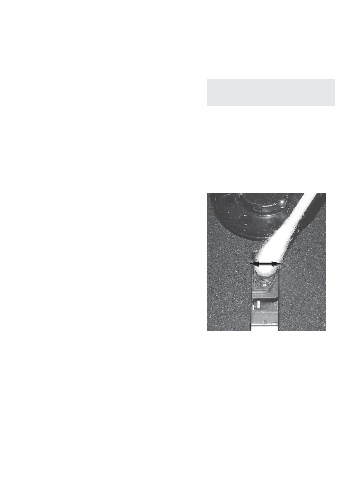
4
LIQUID LENS CLEANING
Before touching the lens it is advised to clean the
surface of the lens by blowing clean air over it.
This to avoid that little particles make scratches on
the lens.
Because the material of the lens is synthetic and coated
with a special anti-reflectivity layer, cleaning must be done
with a non-aggressive cleaning fluid. It is advised to use
“Cleaning Solvent B4-No2”, available with codenumber
4822 389 10026.
The actuator is a very precise mechanical component and
may not be damaged in order to guarantee its full function.
Clean the lens gently (don’t press too hard) with a soft and
clean cotton bud moistened with the special lens cleaner.
The direction of cleaning must be in the way as indicated in
the picture below.
2
CUSTOMER INFORMATION
It is proposed to add an addendum sheet to the set which
informs the customer that the set has been checked
carefully - but no fault was found.
The problem was obviously caused by a scratched, dirty or
copy-protected CD. In case problems remain, the customer
is requested to contact the workshop directly.
The lens cleaning (method 3) should be mentioned in the
addendum sheet.
The final wording in national language as well as the printing
is under responsibility of the Regional Service Organizations.
3
FAST LENS CLEANING (dry brush)
Use lens cleaning CD
SBC AC300...........................................9082 100 00043
Insert the lens cleaning CD, press PLAY and follow the
voice guide´s instructions on the CD.
Sanyo DA12T3
CD Drive
A
A
F
C
B
E
C
D
E
VCC
B
VREF
F
D
9
10
11
12
13
14
15
16
1800
+5V_HF
VrefCD10
A
D
E
B
C
F
GND
8
E
D
A
B
C
F
Laser power control
100n
2878
470n
2876
3821
1R
1K
3823
2880
33p
+5V
BC807-40
7879
3817
47R
3820
4R7
47R
3819
1n
2879
2877
47u
1
8
4
7811-A
LM358D
3
2
10K
3822
47R
3818
2841
100n
47n
2869
+5V_HF
LASER DIODE
U >250mV
->Laser damaged !
4,6V
3V
3,3V
3,9V
2V
0,17V
0,17V
Sanyo
DA12T3
HF-Amplifier
D3
D2
D1
680R
3905
3903
3K3
BC847B
7877
47n
2818
1K5
3902
5
7
4
2
1
6
3
64
8
9
10
11
470R
3893
+3.3V
2K2
3908
10K
3923
BC847B
7878
BC847B
7876
4n7
2813
3896
100R
220u
2885
2881
560p
47n
2887
560R
3901
2883
470n
2817
4u7
3n3
2814
3898
220R
3895
27K
470n
2884
+3.3V
3909
820R
3907
100R
3920
33K
3897
2882
82p
3K3
3904
2K7
3899
3906
470R
+5V_HF
HFIN
VrefCD10
100p
28152816
22n
LDON
to 3826,3827
VREF GE
VDDA1
VRIN
VSSA1
ISLICE
LD
ON
D1
D2
D3
D4
HFIN
HFREF
IREF
CD_DA: 0V / CD_RW: 3V
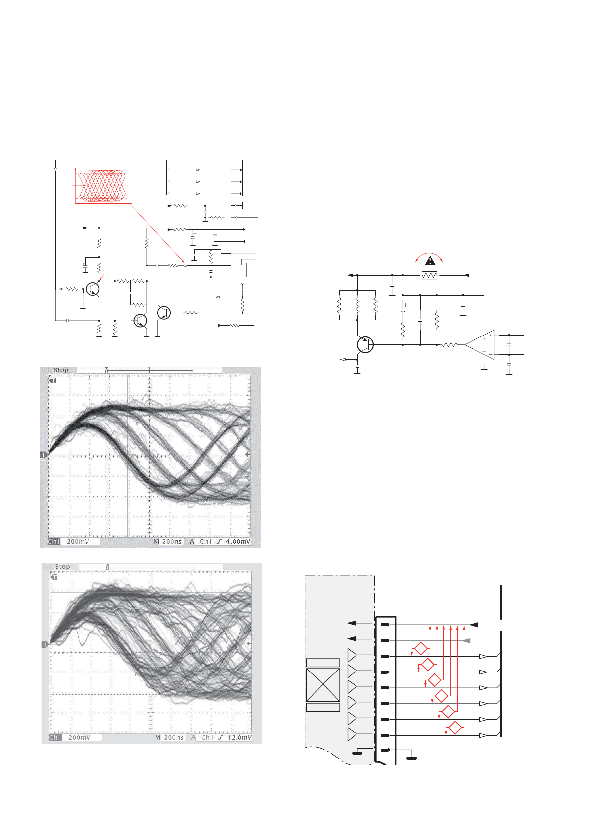
Σ (A-D)
800mVpp
TB = 0.5µs/div
EYE-PATTERN
1,8V
1,2V
2,4V
2,6V
0,65V
CD PLAYABILITY CHECK
1-8
5
EYE-PATTERN SIGNAL – JITTER MEASUREMENT
Measure the signal on the input of the Signal processor
using an analog oscilloscope. Please find the exact
measuring point in your Service Manual.
See below examples of the signal. Amplitude should read at
least 700mVpp using SBC444A.
6
CD DRIVE – LASER CURRENT MEASUREMENT
The laser current can be measured as a voltage drop on a
resistor. The resistor is marked in every Service Manual.
The value depends on the type of CD drive.
typical value most probably defect
VAMxxxx : 150-230mV ≥350mV
MCDxx : 170-230mV ≥300mV
DA1x : 210-250mV ≥350mV
DA2x : 175-200mV ≥250mV
Use SBC444A (CD-DA) for measurement.
If the oscilloscope shows a signal like the ‘bad’ one, and/or
the amplitude decreases within 1 minute - the CD drive has
to be replaced.
good
bad
7
CD DRIVE – OFFSET MEASUREMENT
The photodiodes of the CD-drive may have an offset. These
offsets have to be compensated by the signal processor.
High offsets can lead to poor playability of some CDs
(skipping tracks).
To measure the offset values, start the Service Test
Program - section “Focus Test” without a CD.
The offsets can be measured with a DC Millivoltmeter
directly on the connector (see drawing below). Pin
numbering varies from drive to drive.
The values from diode A-D should read 0±10mV.
Diodes E and F are less critical.
If one of the offsets is higher than ±10mV the CD drive has
to be replaced. Otherwise replace the Signal Processor.
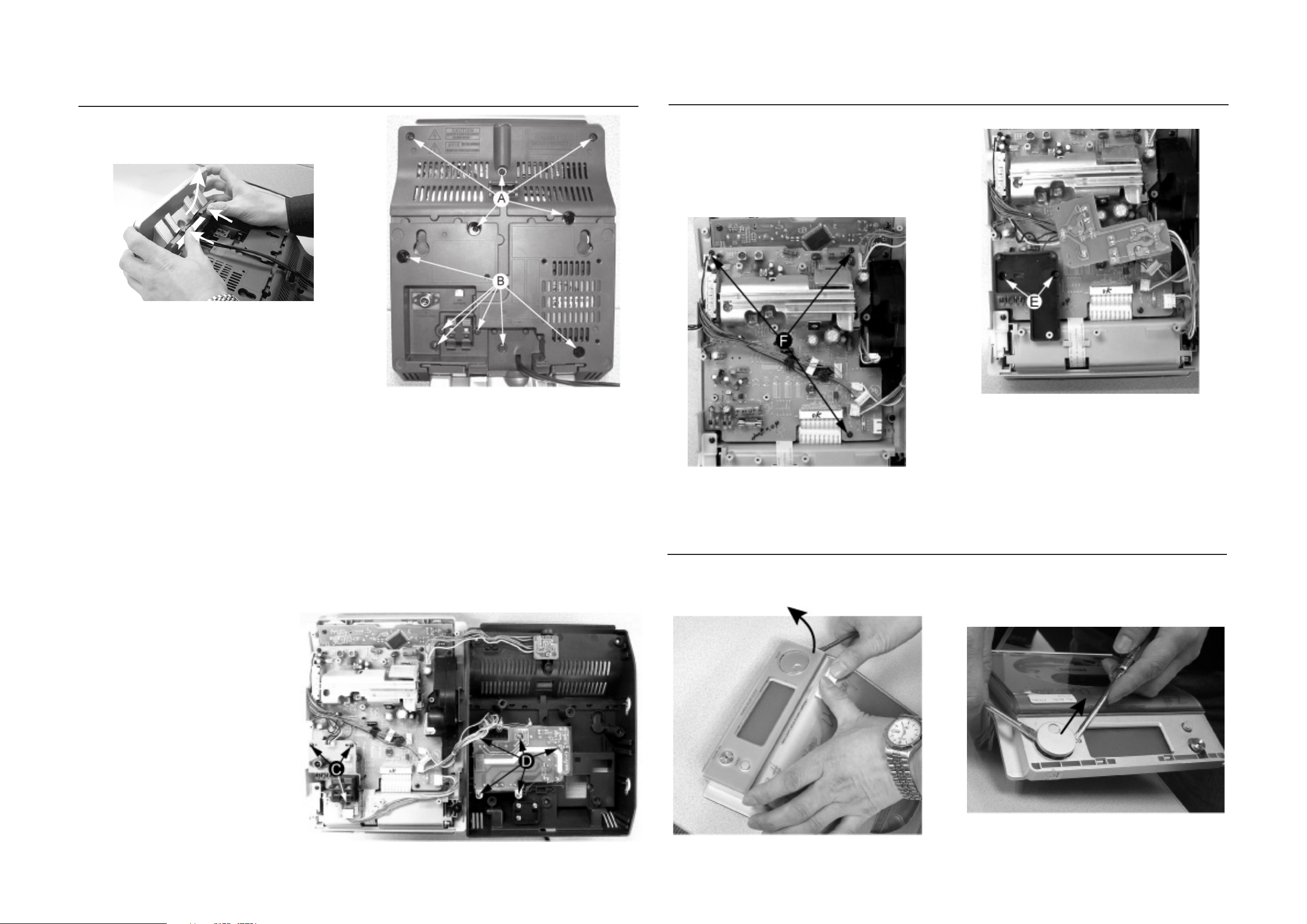
DISMANTLING INSTRUCTIONS
2-1 2-1
Dismantling the Rear Portion and PCBs
1) Press the 2 juts and pull out the Stand as shown in figure
1.
Figure 1
Figure 2
Dismantling the Rear Portion and PCBs
5) Loosen 2 screws E to remove the Bracket Jack Board as
shown in Figure 4.
6) Loosen 3 screws F to remove the Main Board as shown
in figure 5.
Figure 4
2) Loosen 5 screws A and 6 screws B to remove the Rear
Cabinet as shown in figure 2.
3) Loosen 3 screws C to remove the SP & ANT Jack Board
as shown in figure 3.
4) Loosen 5 screws D to remove the Power Module as
shown in figure 3.
Figure 5
Dismantling of the Display Lens & the Volume knob
1) Use a flat head screw driver to give a push in the direction
as shown in figure 6.
2) Place two small screw drivers in between the front cabinet
& knob to give more leverage in pulling out the Volume
Knob as shown in figure 7.
Figure 3
Figure 7
Figure 6
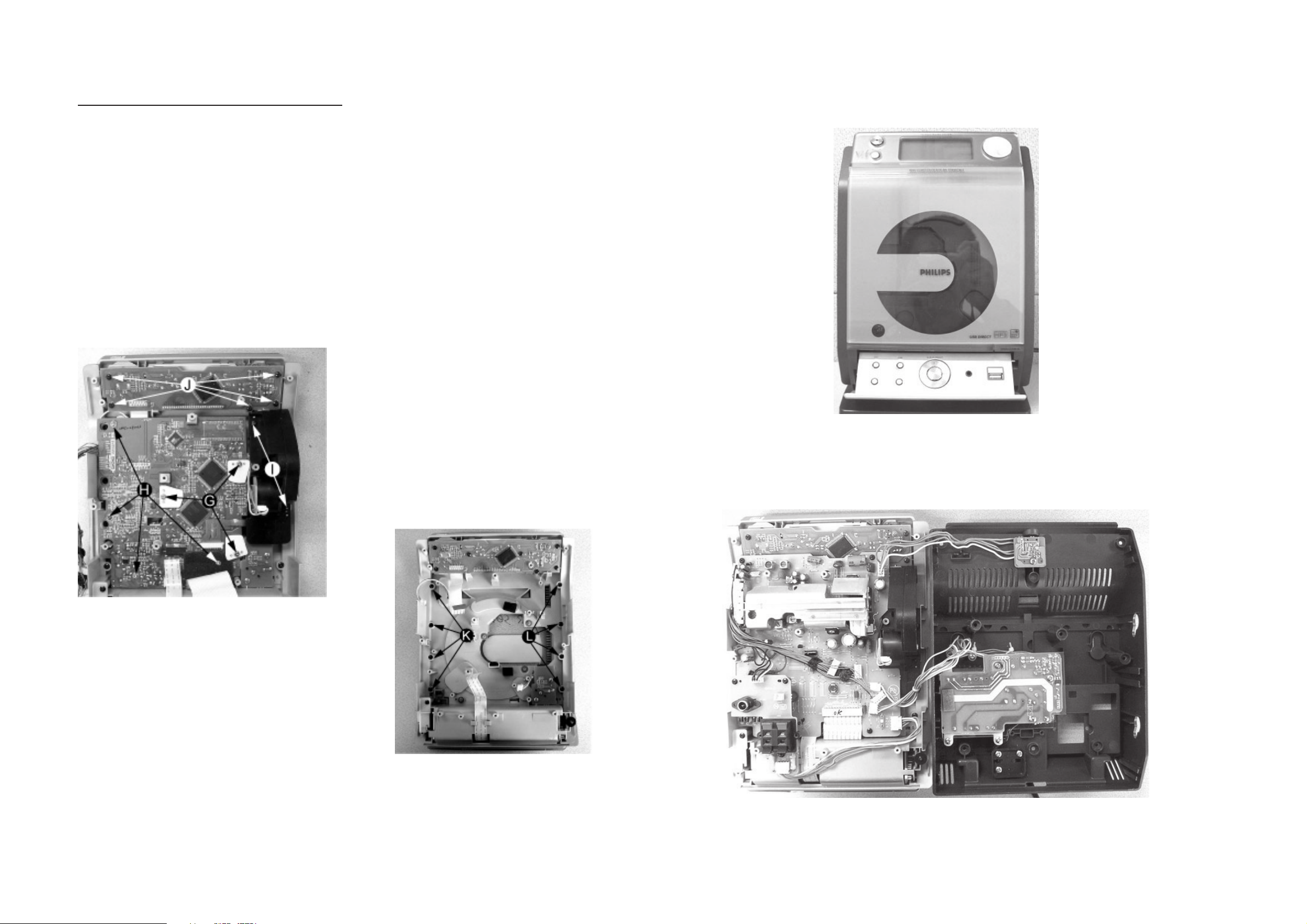
Dismantling of the CD Module & CD Door Carrier
1) Loosen 5 screws J mounting the Key Board to the Front
Cabinet to remove the Key Board as shown in figure 8.
2) Loosen 4 screws H and 3 screws G to CD Module as
shown in figure 8.
3) Loosen 2 screws I to remove the Servo Motor Mechanism
as shown in figure 8.
2-2
2-2
Service pos A
Figure 8
4) Loosen 4 screws K to remove the Right CD Door Carrier
and 4 screws L to remove the Left CD Door Carrier as
shown in figure 9.
Service pos B
Figure 9
Note: After re-assembly, it is very important to ensure all
wires are routed properly to ensure that they do not
touch/obstruct all moving parts.
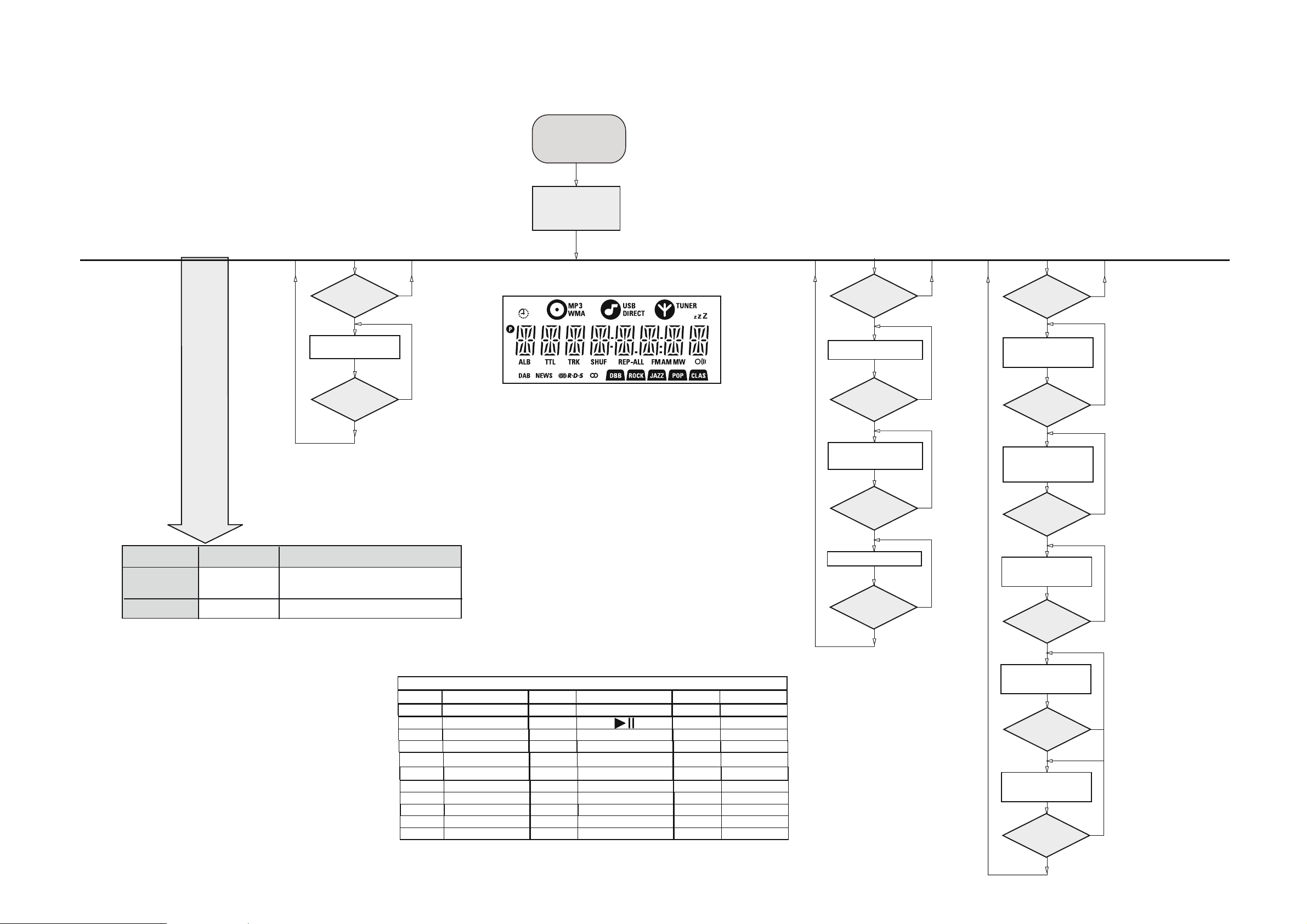
SERVICE TEST PROGRAM
3-1
3-1
KEY
TEST
Button pressed?
Button pressed?
NEXT
Y
Display shows
Table 1
9
Y
To enter Service
Testprogram hold
DBB & Source buttons
depressed for 3 sec.
at USB mode (no USB).
Display shows the
MCU version
“ V. yy ”
(Main menu)
N
N
Figure 1
Door switch is ignored →
*
V refers to Version
yy refers to Software version number of the uProcessor
(counting up from 01 to 99)
CD door can be opened.
DISPLAY
TEST
PREV
Button pressed?
Y
Display shows Figure 1
All display flags on.
PREV
Button pressed?
Y
Display shows alternate
segment display from SEG0
to SEG64.
ADC
TEST
N
N
DBB
Button pressed?
Y
Display shows "ADC0 Value"
for ADC0
(Input Line - For key scanning)
DBB
Button pressed?
Y
Display shows "ADC1 Value"
for ADC1
(Input Line - ioNTC Heat
detection for transformer)
N
N
TEST
E
E
LEAVE SERVICE
TEST PROGRAM
other Tests
RAELC MORP
Various
Activated with
PROGRAM
9
to Exit
Disconnect
mains cord
ACTION
A
set
"EEP CLR" is displayed while the erase processing.
Caution! All presets from the customer will be lost!!
.MORPEE eht ot tnes eb lliw nrettap t
KeyNr Set key KeyNr Set key KeyNr Set key
0 CD 10 RDS 20 PROGRAM
1 AUX 11
2 TUNER 12 CLOCK/DISP
3 SOURCE 13 ALBUM + SLEEP
4
STANDBY/ON
5
OPEN/CLOSE
6
VOLUME DOWN
7 VOLUME UP 17 NULL 27 MUTE
8 NULL 18 NULL 28 USB
9 NULL 19 REPEAT
Key test table
21 SHUFFLE
LAY
14 ALBUM - TIMER
15
SKIP PREV 25 DBB
16 SKIP NEXT 26 DSC
Table 1
22 NULL
23
24
PREV
Button pressed?
Y
No Display shows
9
Button pressed?
Y
ADC Test is used for checking the
ADC inputs to the microprocessor.
The display shows an ADC value
between 0 and 255 for an input
signal between 0 and 5V.
N
N
DBB
Button pressed?
Y
Display shows "ADC2 Value"
for ADC2
(Input Line - Rotary volume)
DBB
Button pressed?
Y
Display shows "ADC3 Value"
for ADC3
(Input Line - Door switch status)
DBB
Button pressed?
Y
Display shows "ADC4 Value"
for ADC4
(Input Line - Version detection)
9
Button pressed?
Y
N
N
N
N
 Loading...