

Page 1

IntuiKey Series
Digital Keyboard
Philips
Communication,
Security & Imaging
Instructions for Use
Eng
Page 2

3
IMPORTANT SAFEGUARDS
1. Read Instructions - All the safety and operating instructions should be read
before the unit is operated.
2. Retain Instructions - The safety and operating instructions should be
retained for future reference.
3. Heed Warnings - All warnings on the unit and in the operating instructions
should be adhered to.
4. Follow Instructions - All operating and use instructions should be followed.
5. Cleaning - Unplug the unit from the outlet before cleaning. Do not use
liquid cleaners or aerosol cleaners. Use a damp cloth for cleaning.
6. Attachments - Do not use attachments not recommended by the product
manufacturer as they may cause hazards.
7. Water and Moisture - Do not use this unit near water - for example, in a
wet basement, near a swimming pool, in an unprotected outdoor
installation, or in any area which is classified as a wet location.
8. Accessories - Do not place this unit on an unstable stand, tripod, bracket,
or mount. The unit may fall, causing serious injury to a person and serious
damage to the unit. Use only with a stand, tripod, bracket, or mount
recommended by the manufacturer or sold with the product. Any
mounting of the unit should follow the manufacturer’s instructions and
should use a mounting accessory recommended by the manufacturer.
An appliance and cart combination should be moved with care.
Quick stops, excessive force, and uneven surfaces may cause the appliance
and cart combination to overturn.
9. Ventilation - Openings in the enclosure, if any, are provided for ventilation,
to ensure reliable operation of the unit, and to protect it from overheating.
These openings must not be blocked or covered. This unit should not be
placed in a built-in installation unless proper ventilation is provided or the
manufacturer’s instructions have been adhered to.
10. Power Sources - This unit should be operated only from the type of power
source indicated on the marking label. If you are not sure of the type of
power supply you plan to use, consult your dealer or local power company.
For units intended to operate from battery power or other sources, refer to
the operating instructions.
11. Grounding or Polarization - This unit may be equipped with a polarized
alternating-current line plug (a plug having one blade wider than the other).
This plug will fit into the power outlet only one way. This is a safety
feature. If you are unable to insert the plug fully into the outlet, try
reversing the plug. If the plug should still fail to fit, contact your electrician
to replace your obsolete outlet. Do not defeat the safety purpose of the
polarized plug.
Alternately, this unit may be equipped with a 3-wire grounding-type plug, a
plug having a third (grounding) pin. This plug will only fit into a
grounding-type power outlet. This is a safety feature. If you are unable to
insert the plug into the outlet, contact your electrician to replace your
obsolete outlet. Do not defeat the safety purpose of the grounding-type
plug.
12. Power Cord Protection - Power supply cords should be routed so that they
are not likely to be walked on or pinched by items placed upon or against
them, paying particular attention to cords and plugs, convenience
receptacles, and the point where they exit from the appliance.
13. Power Lines - An outdoor system should not be located in the vicinity of
overhead power lines or other electric light or power circuits or where it
can fall into such power lines or circuits. When installing an outdoor
system, extreme care should be taken to keep from touching such power
lines or circuits as contact with them might be fatal. U.S.A. models only refer to the National Electrical Code Article 820 regarding installation of
CATV systems.
14. Overloading - Do not overload outlets and extension cords as this can result
in a risk of fire or electric shock.
15. Object and Liquid Entry - Never push objects of any kind into this unit
through openings, as they may touch dangerous voltage points or short out
parts that could result in a fire or electric shock. Never spill liquid of any
kind on the unit.
16. Servicing - Do not attempt to service this unit yourself as opening or
removing covers may expose you to dangerous voltage or other hazards.
Refer all servicing to qualified service personnel.
17. Damage Requiring Service - Unplug the unit from the outlet and refer
servicing to qualified service personnel under the following conditions:
a. When the power supply cord or plug is damaged.
b. If liquid has been spilled or objects have fallen into the unit.
c. If the unit has been exposed to water and/or inclement weather
(rain, snow, etc).
d. If the unit does not operate normally by following the operating
instructions. Adjust only those controls that are covered by the
operating instructions, as an improper adjustment of other controls
may result in damage and will often require extensive work by a
qualified technician to restore the unit to its normal operation.
e. If the unit has been dropped or the cabinet has been damaged.
f. When the unit exhibits a distinct change in performance—this
indicates a need for service.
18. Replacement Parts - When replacement parts are required, be sure the
service technician has used replacement parts specified by the manufacturer
or have the same characteristics as the original part. Unauthorized
substitutions may result in fire, electric shock, or other hazards.
19. Safety Check - Upon completion of any service or repairs to this unit, ask
the service technician to perform safety checks to determine that the unit is
in proper operating condition.
20. Coax Grounding - If an outside cable system is connected to the unit, be
sure the cable system is grounded. U.S.A. models only—Section 810 of the
National Electrical Code, ANSI/NFPA No.70-1981, provides information
with respect to proper grounding of the mount and supporting structure,
grounding of the coax to a discharge unit, size of grounding conductors,
location of discharge unit, connection to grounding electrodes, and
requirements for the grounding electrode.
21. Lightning - For added protection of this unit during a lightning storm, or
when it is left unattended and unused for long periods of time, unplug it
from the wall outlet and disconnect the cable system. This will prevent
damage to the unit due to lightning and power line surges.
FCC & ICES INFORMATION
(U.S.A. and Canadian Models Only)
WARNING - This equipment has been tested and found to comply with the
limits for a Class A digital device, pursuant to Part 15 of the FCC Rules and
ICES-003 of Industry Canada. These limits are designed to provide reasonable
protection against harmful interference when the equipment is operated in a
commercial environment. This equipment generates, uses, and radiates radio
frequency energy and, if not installed and used in accordance with the
instruction manual, may cause harmful interference to radio communications.
Operation of this equipment in a residential area is likely to cause harmful
interference in which case the user will be required to correct the interference at
his own expense. Intentional or unintentional changes or modifications not
expressly approved by the party responsible for compliance shall not be made.
Any such changes or modifications could void the user's authority to operate the
equipment.
If necessary, the user should consult the dealer or an experienced radio/television
technician for corrective action . The user may find the following booklet
prepared by the Federal Communications Commission helpful: "How to
Identify and Resolve Radio-TV Interference Problems." This booklet is
available from the U.S. Government Printing Office, Washington, DC 20402,
Stock No.004-000-00345-4.
For additional information or to speak to a representative,
please contact the Philips Communication, Security &
Imaging location nearest you:
The Americas: 1 800 326 3270
Europe & Middle East: +31 40 278 1222
Asia Pacific Region: +65 350 1859
or visit our Web site at www.philipscsi.com.
Wa rning: This is a Class A product. In a domestic
environment, this product may cause radio interference in
which case the user may be required to take adequate measures.
Page 3
4
SAFETY PRECAUTIONS
The lightning flash with an arrowhead symbol within
an equilateral triangle is intended to alert the user to
the presence of uninsulated “dangerous voltage” within
the product’s enclosure that may be of sufficient
magnitude to constitute a risk of electric shock to
persons.
The exclamation point within an equilateral triangle is
intended to alert the user to presence of important
operating and maintenance (servicing) instructions in
the literature accompanying the appliance.
Attention: Installation should be performed by
qualified service personnel only in accordance with the
National Electrical Code or applicable local codes.
Power Disconnect. Units with or without ON-OFF
switches have power supplied to the unit whenever the
power cord is inserted into the power source; however,
the unit is operational only when the ON-OFF switch
is in the ON position. The power cord is the main
power disconnect for all units.
Battery Replacement Caution
Use only the Recommended Power Supplies. Power
supplies must comply with the requirements of the
latest version of IEC 65/VDE 0860. Substitutions may
damage the unit or cause a fire or shock hazard.
SECURITE
L’éclair fléché dans un triangle équilatéral avertit
l’utilisateur de la présence d’une “tension dangereuse” non
isolée à l’intérieur de l’appareil et d’une valeur suffisante
pour présenter un risque d’électrocution aux personnes.
Le point d’exclamation contenu dans un triangle
équilatéral avertit l’utilisateur de la présence de
consignes d’utilisation et de maintenance importantes
dans la documentation qui accompagne l’appareil.
Attention. L’installation ne doit être effectuée que par
un personnel technique qualifié conformément à la
réglementation du Code Électrique National ou à la
réglementation locale pertinente.
Disjonction de l’alimentation. Les appareils avec ou
sans commutateurs ON-OFF sont alimentés à chaque
fois que le cordon d’alimentation est branché à la source
d’alimentation; toutefois, les appareils disposant de
commutateurs ON-OFF ne fonctionnent que lorsque le
commutateur ON-OFF est dans la position ON. Le
cordon d’alimentation constitue le moyen de disjonction
de l’alimentation principale de tous les appareils.
Mise en garde pour le remplacement de la pile
Utiliser uniquement les alimentations préconisées.
Les alimentations doivent être conformes aux exigences
de la dernière version de la norme IEC 65/VDE
0860. Toute substitution peut endommager l’appareil
et présenter un risque d’incendie ou d’électrocution.
CAUTION:TO REDUCE THE RISK OF
ELECTRICAL SHOCK, DO NOT OPEN
COVERS.NO USER SERVICEABLE PARTS
INSIDE. REFER SERVICING TO QUALIFIED
SERVICE PERSONNEL.
WARNING
TO PREVENT FIRE OR SHOCK HAZARD, DO
NOT EXPOSE UNITS NOT SPECIFICALLY
DESIGNED FOR OUTDOOR USE TO RAIN OR
MOISTURE.
DANGER : POUR ÉVITER TOUT RISQUE
D’ÉLECTROCUTION,VEUILLEZ NE PAS
OUVRIR LE BOÎTIER. IL N’Y A PAS DE PIÈCES
REMPLAÇABLES PAR L’UTILISATEUR À
L’INTÉRIEUR DU BOÎTIER. POUR TOUTE
MAINTENANCE,VEUILLEZ VOUS ADRESSER
À UN TECHNICIEN SPÉCIALISÉ.
ATTENTION
POUR ÉVITER TOUT RISQUE
D’ÉLECTROCUTION OU D’INCENDIE,
VEUILLEZ NE PAS EXPOSER À LA PLUIE OU
À L’HUMIDITÉ UN APPAREIL NON CONÇU
POUR UNE UTILISATION EXTÉRIEURE.
Page 4
5
SICHERHEITSHINWEISE
Das Blitzsymbol im gleichseitigen Dreieck soll den
Benutzer auf nicht isolierte “gefährliche Spannung” im
Produkt hinweisen, die ausreichend stark sein kann,
um die Gefahr von elektrischen Schlägen für
Menschen darzustellen.
Das Ausrufungszeichen im gleichseitigen Dreieck soll
den Benutzer auf wichtige Bedienungs- und
Wartungsanweisungen in der Dokumentation
hinweisen, die dem Gerät beiliegt.
Achtung: Die Installation darf nur von qualifiziertem
Wartungspersonal gemäß dem National Electrical
Code oder den gültigen örtlichen Vorschriften
durchgeführt werden.
Abtrennen der Spannungsversorgung: Die
Spannungsversorgung zu Geräten mit und ohne
Ein/Aus-Schalter ist hergestellt, wenn das Netzkabel an
eine Netzsteckdose angeschlossen ist. Das Gerät ist
jedoch nur betriebsbereit, wenn der Ein/Aus-Schalter
eingeschaltet ist. Bei allen Geräten erfolgt das Abtrennen
der Spannungsversorgung über das Netzkabel.
Zur Beachtung beim Batteriewechsel
Nur empfohlene Netzteile verwenden. Netzteile
müssen den Anforderungen der neuesten Version von
IEC 65/VDE 0860 genügen. Durch die Verwendung
anderer Netzteile kann das Gerät beschädigt oder ein
Feuer oder Stromschlag verursacht werden.
SEGURIDAD
El símbolo de flecha en forma de rayo situado dentro
de un triángulo equilátero pretende alertar al usuario
de la presencia de “voltaje peligroso” sin aislamiento
dentro de la caja del producto, el cual podría resultar
de una magnitud suficiente como para presentar un
riesgo de descarga eléctrica para las personas.
El punto de exclamación dentro de un triángulo equilátero
pretende alertar al usuario de la existencia de instrucciones
de funcionamiento y mantenimiento (reparación) en la
documentación suministrada con el aparato.
Atención: La instalación debe realizarla personal
cualificado en cumplimiento estricto del código
eléctrico nacional (en el caso de los EE.UU.) o de los
códigos locales aplicables.
Para Desconectar la Alimentación: Unidades no
equipadas con interruptores ON/OFF, son alimentadas
cuando el cable de alimentación es conectado a la
corriente eléctrica. Las unidades equipadas con
interruptores son alimentadas de igual forma, pero
adicionalmente requieren que el interruptor esté
posicionado en ON. El cable de alimentación es el
medio principal de desconexión del equipo.
Aviso para la sustitución de baterías
Utilice únicamente las fuentes de alimentación
recomendadas. Las fuentes de alimentación deben
cumplir los requisitos de la versión más moderna de
IEC 65/VDE 0860. Las sustituciones pueden dañar la
unidad o causar incendios e incluso exponer al
usuario al peligro de electrocución.
VORSICHT: DAS GEHÄUSE ZUR VERMEIDUNG
VON ELEKTRISCHEN SCHLÄGEN NICHT
ÖFFNEN. DAS GERÄT ENTHÄLT KEINE VOM
BENUTZER ZU WARTENDEN TEILE.
REPARATUREN NUR VON FACHPERSONAL
AUSFÜHREN LASSEN.
WARNUNG
ZUR VERMEIDUNG VON FEUER UND
ELEKTRISCHEN SCHLÄGEN DAS GERÄT
NICHT REGEN ODER FEUCHTIGKEIT
AUSSETZEN.
PRECAUCIÓN: PARA REDUCIR EL RIESGO DE
DESCARGA ELÉCTRICA, NO ABRA LAS
TA PAS. EN EL INTERIOR NO HAY NINGÚN
COMPONENTE REPARABLE POR EL USUARIO.
LAS REPARACIONES DEBE REALIZARLAS
PERSONAL CUALIFICADO.
AVISO
PARA IMPEDIR EL RIESGO DE INCENDIO O
DESCARGA, NO EXPONGA EL APARATO A
LLUVIA O HUMEDAD
VORSICHT
ELEKTRISCHE SPANNUNG.
NICHT ÖFFNEN!
PRECAUCIÓN
RIESGO DE DESCARGA ELÉCTRICA
¡NO ABRIR!
Page 5
6
VEILIGHEIDSMAATREGELEN
Het symbool ‘Bliksemflits met pijlkop’ in een
gelijkzijdige driehoek wijst de gebruiker op de
aanwezigheid in de kast van het apparaat van nietgeïsoleerde spanningen die voldoende sterk zijn om
het gevaar van elektrische schokken op te leveren.
Het uitroepteken in een gelijkzijdige driehoek maakt
de gebruiker attent op de aanwezigheid in de bij het
apparaat behorende documentatie van belangrijke
aanwijzingen voor bediening en onderhoud.
Let op: Het apparaat mag uitsluitend door bevoegde
technici geïnstalleerd worden en wel in overeenstemming
met de National Electrical Code of de daarvoor
plaatselijk geldende richtlijnen.
Afsluiten voeding. Apparaten met of zonder
ON-OFF-schakelaar krijgen voeding zodra het
netsnoer in de wandcontactdoos wordt gestoken; het
apparaat is echter alleen operationeel als de ON-OFFschakelaar op ON staat. Het netsnoer kan bij alle
apparaten worden gebruikt om deze uit te schakelen.
Let op als u de batterij vervangt!
Gebruik uitsluitend de geadviseerde spanningsbronnen.
Spanningsbronnen moeten voldoen aan de meest
recente uitgave van de IEC 65/VDE 0860
voorschriften. Spanningsbronnen die hieraan niet
voldoen, kunnen het apparaat beschadigen of gevaar
opleveren voor brand en elektrische schokken.
SICUREZZA
Il simbolo triangolare di un fulmine con la punta a
freccia intende mettere in allerta l’utente riguardo alla
presenza di tensioni pericolose non isolate all’interno
del guscio dell’unità, che potrebbero essere di intensità
sufficiente per costituire pericolo di elettrocuzione.
Il punto esclamativo racchiuso in un triangolo equilatero
intende avvisare l’utente in merito alla presenza di
importanti istruzioni operative e di manutenzione nella
documentazione di accompagnamento all’unità.
Precauzione: affidare l’installazione al solo personale
qualificato e nel rispetto del Codice elettrico nazionale
(USA) o dei codici locali pertinenti.
Scollegamento dell’alimentazione. Gli apparecchi con
o senza commutatori ON-OFF ricevono corrente tutte
le volte che il cavo di alimentazione è inserito nella presa
di forza; tuttavia, gli apparecchi muniti di commutatore
ON-OFF funzionano solo se quest’ultimo è in posizione
ON. Il cavo di alimentazione serve a scollegare dalla
corrente tutti gli apparecchi.
Precauzione per la sostituzione della batteria
Utilizzare esclusivamente uno degli alimentatori
consigliati. Gli alimentatori devono essere conformi ai
requisiti della versione più recente delle norme IEC
65/VDE 0860. L’uso di un adattatore non conforme
potrebbe arrecare danni all’unità o costituire un
pericolo d’incendio o scossa elettrica.
VOORZICHTIG:MAAK HET APPARAAT NIET
OPEN OM DE KANS OP ELEKTRISCHE
SCHOKKEN TE VERMIJDEN. BEVAT GEEN
ONDERDELEN DIE DOOR DE GEBRUIKER
MOETEN WORDEN ONDERHOUDEN. LAAT
ONDERHOUD EN REPARATIES UITVOEREN
DOOR BEVOEGDE TECHNICI.
WAARSCHUWING
TER VOORKOMING VAN BRANDGEVAAR EN
ELEKTRISCHE SCHOKKEN MAG DIT
ARMATUUR NIET AAN REGEN EN VOCHT
WORDEN BLOOTGESTELD.
ATTENZIONE: PER RIDURRE IL PERICOLO DI
SCOSSA ELETTRICA, NON APRIRE LE
COPERTURE.L’INTERNO NON CONTIENE
COMPONENTI CHE L’UTENTE PUÒ RIPARARE
PERSONALMENTE. RIVOLGERSI AL
PERSONALE DI ASSISTENZA QUALIFICATO
PER QUALSIASI INTERVENTO DI
RIPARAZIONE.
AVVERTENZA
PER IMPEDIRE INCENDI O SCOSSA
ELETTRICA, NON ESPORRE L’UNITÀ ALLA
PIOGGIA O ALL’UMIDITÀ.
VOORZICHTIG
GEVAAR VOOR ELEKTRISCHE SCHOK.
NIET OPENEN!
ATTENZIONE
PERICOLO DI SCOSSA ELETTRICA.
NON APRIRE.
Page 6
7
O símbolo do raio com a cabeça de uma seta dentro
de um triângulo equilátero serve para alertar o utilizar
para a presença de "corrente eléctrica perigosa" não
isolada no interior da caixa do produto que pode ser
suficiente para dar origem a choques eléctricos.
O ponto de exclamação dentro de um triângulo equilátero
serve para alertar o utilizador para a presença de instruções
de funcionamento e manutenção importantes na documentação fornecida com o aparelho.
Atenção: A instalação deve ser efectuada por pessoal de
assistência técnica qualificado, de acordo com o
National Electrical Code (Normas de Electricidade
Nacionais) ou a legislação local aplicável.
Desconexão da electricidade. Unidades com ou sem
interruptores ON-OFF são activadas sempre que o
cabo eléctrico for ligado a uma fonte de alimentação.
No entanto, a unidade fica operacional apenas quando
o interruptor ON-OFF se encontrar na posição ON.
Para desligar a electricidade em qualquer uma das
unidades deve ser utilizado o cabo eléctrico.
Precauções a ter durante a substituição da bateria
Use apenas fontes de alimentação recomendadas. As
fontes de alimentação devem cumprir os requisitos da
da versão mais recente de IEC 65/VDE 0860.
Qualquer substituição pode causar danos na unidade
ou dar origem a incêndios ou choques eléctricos.
CUIDADO: PARA REDUZIR O RISCO DE
CHOQUE ELÉCTRICO, NÃO ABRA AS TAMPA S. O INTERIOR NÃO CONTÉM PEÇAS QUE
NECESSITEM DE MANUTENÇÃO.A
MANUTENÇÃO DEVE SER EFECTUADA POR
PESSOAL DE ASSISTÊNCIA TÉCNICA QUALIFICADO.
AVISO
PARA EVITAR INCÊNDIOS OU CHOQUES
ELÉCTRICOS, NÃO EXPONHA À CHUVA OU
HUMIDADE UNIDADES NÃO ESPECIFICAMENTE CRIADAS PARA UTILIZAÇÃO NO
EXTERIOR.
ZASADY BESPIECZE ´NSTAWA
MEDIDAS DE SEGURANÇA
UWAGA
NIEBEZPIECZEŃSTWO PORAŻENIA PRĄDEM
ELEKTRYCZNYM. NIE OTWIERAĆ!
UWAGA: ZE WZGLĘDU NA
NIEBEZPIECZEŃSTWO PORAŻENIA PRĄDEM
NIE WOLNO OTWIERAĀ POKRYWY.W
ŚRODKU NIE MA ŻADNYCH ELEMENTÓW,
KTÓRE MOGĄ BYĀ NAPRAWIANE PRZEZ
UŻYTKOWNIKA. NAPRAWĘ NALEŻY
POWIERZYĀ AUTORYZOWANEMU PUNKTOWI SERWISOWEMU.
Błyskawica ze strzałką wewnątrz trójkąta równobocznego
ma za zadanie zwrócić uwagę użytkownika na obecność
nieizolowanego "niebezpiecznego napięcia" wewnątrz
obudowy urządzenia, o wielkości stwarzającej niebezpieczeństwo porażenia prądem.
Wykrzyknik wewnątrz trójkąta równobocznego ma za
zadanie zwrócić uwagę użytkownika na ważne czynności,
związane z obsługą i konserwacją urządzenia, zamieszczone w Instrukcji obsługi.
OSTRZEŻENIE
ABY UNIKNĄĀ POŻARU LUB PORAŻENIA
PRĄDEM NIE WOLNO WYSTAWIAĀ NA
DZIAŁANIE DESZCZU LUB WILGOCI
URZĄDZEŃ, KTÓRE NIE ZOSTAŁY SPECJALNIE
ZAPROJEKTOWANE DO UŻYWANIA NA
OTWA RTYM POWIETRZU.
Uwaga: Instalację urządzenia powinien wykonać tylko
wykwalifikowany personel, zgodnie z przepisami NEC lub
odpowiednimi przepisami miejscowymi.
Odłączanie zasilania. Urządzenia zarówno nie posiadające, jak i posiadające wyłączniki ON-OFF znajdują się
pod napięciem, jeżeli tylko przewód zasilający jest
połączony ze źródłem zasilania. Jednakże urządzenie
działa tylko wtedy, gdy wyłącznik znajduje się w położeniu
ON. Przewód zasilający jest głównym odłącznikiem zasilania dla wszystkich rodzajów urządzeń.
Wymiana baterii
Stosuj tylko zalecane baterie. Muszą one spełniać wymagania najnowszej wersji IEC 65/VDE 0860. Zamienniki
mogą uszkodzić urządzenie lub spowodować pożar czy
porażenie prądem.
CUIDADO
RISCO DE CHOQUE ELÉCTRICO.
NÃO ABRIR!
Page 7

8
TABLE OF CONTENTS
1 INTRODUCTION TO THE INTUIKEY DIGITAL KEYBOARD SERIES..............................................10
1.1 Guide to This Manual ......................................................................................................................................10
1.2 Unpacking ........................................................................................................................................................10
1.3 Service ..............................................................................................................................................................10
1.4 Understanding the IntuiKey ..............................................................................................................................10
2 INSTALLING THE INTUIKEY DIGITAL KEYBOARD..........................................................................11
2.1 Determining the IntuiKey System Configuration ..............................................................................................11
2.2 Mounting the IntuiKey......................................................................................................................................12
2.3 Connecting the IntuiKey ..................................................................................................................................12
3OPERATING THE INTUIKEY DIGITAL KEYBOARD ..........................................................................14
3.1 Learning the IntuiKey Components ..................................................................................................................14
3.1.1 The Status Display ........................................................................................................................................................14
3.1.2 The Keypad ..................................................................................................................................................................14
3.1.3 The Softkeys and the Softkey Display..............................................................................................................................14
3.1.4 The Joystick ..................................................................................................................................................................14
3.2 Navigating the System with the IntuiKey Keyboard ........................................................................................15
3.2.1 General Guidelines for Navigating the IntuiKey Menus ..................................................................................................15
3.2.2 The Product Selection Menu..........................................................................................................................................15
3.2.3 Selecting a Device for Control........................................................................................................................................15
3.2.4 Easy Switching Between Devices ....................................................................................................................................15
3.2.5 Using the Keypad for Numeric Entry (Camera Control)..................................................................................................15
3.2.6 Using the Quick Selection Softscreen Feature ..................................................................................................................15
3.3 Alarm/Alert/Action Indication ..........................................................................................................................16
3.4 Configuring the IntuiKey Keyboard ..................................................................................................................16
3.4.1 Accessing the Keyboard Control Menu ............................................................................................................................16
3.4.2 Keyboard Control Menu Options ..................................................................................................................................16
4CONTROLLING ALLEGIANT®SERIES VIDEO SWITCHERS ............................................................17
4.1 The Allegiant Main Control Menu....................................................................................................................17
4.1.1 Accessing the Allegiant Main Control Menu ..................................................................................................................17
4.2 Programming/Controlling Allegiant Functions ..................................................................................................17
4.2.1 Allegiant Main Control Menu Command Descriptions ..................................................................................................17
4.3 Allegiant Error Messages....................................................................................................................................22
4.4 ADIM Error Messages ......................................................................................................................................24
5CONTROLLING Divar SERIES DIGITAL VIDEO RECORDERS ........................................................25
5.1 The Divar Main Control Menu ........................................................................................................................25
5.1.1 Accessing the Divar Main Control Menu ......................................................................................................................25
5.2 Programming/Controlling DVR Functions........................................................................................................25
5.2.1 The DVR Main Control Menu......................................................................................................................................25
5.2.2 DVR On-Screen Menu Controls ....................................................................................................................................26
5.2.3 DVR Control Menu ......................................................................................................................................................27
5.3 DVR Error Messages..........................................................................................................................................28
6CONTROLLING System4
®
VIDEO MULTIPLEXERS ............................................................................29
6.1 The Mux Main Control Menu ..........................................................................................................................29
6.1.1 Accessing the Mux Main Control Menu..........................................................................................................................29
6.2 Programming/Controlling Mux Functions ........................................................................................................29
Page 8

9
6.2.1 Password Entry..............................................................................................................................................................29
6.2.2 Mux Main Control Menu Command Descriptions..........................................................................................................29
6.3 Mux Error Messages ..........................................................................................................................................31
7TROUBLESHOOTING ............................................................................................................................32
7.1 System ..............................................................................................................................................................32
7.2 Keyboard ..........................................................................................................................................................32
7.3 Camera Control ................................................................................................................................................32
7.4 Miscellaneous ....................................................................................................................................................32
APPENDIX A: INTUIKEY MENU REFERENCE ............................................................................................33
APPENDIX B: CAMERA CONTROL COMMAND REFERENCE..................................................................34
APPENDIX C: INTUIKEY & KBD-SFTCFG COMPATIBILITY ....................................................................42
APPENDIX D: SECURITY INFORMATION....................................................................................................43
Page 9
10
1 INTRODUCTION TO THE INTUIKEY
DIGITAL KEYBOARD SERIES
1.1 Guide to This Manual
This manual contains all the information necessary to safely install
and operate the IntuiKey Digital Keyboard. Consult the Table of
Contents for a detailed list of topics covered. Step-by-step
procedures, illustrations, and sample menus guide you through
each phase of IntuiKey setup and operation.
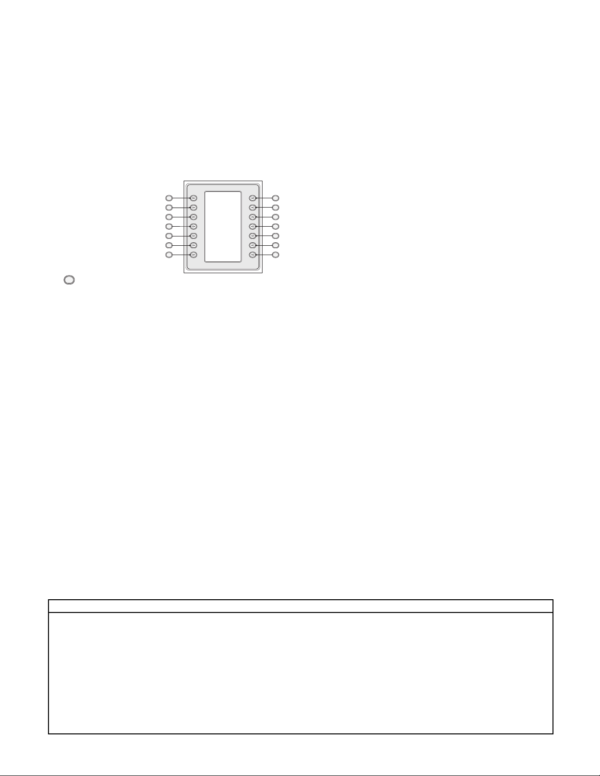
Throughout the manual, you will see sample drawings of each
menu as they appear on the keyboard. These drawings display the
softkey text in relation to the Softkey. For the purposes of this
manual, each key is
numbered from 1 to 14,
using the convention found
in Figure 1-1.
Following the menu diagram,
the function of each key is
described in a paragraph
indicated with an Icon such
as “ ” clearly identifying
the particular softkey.
Installation of the IntuiKey includes mounting and connecting the
unit to other system components. The plug and play design makes
installation and setup of the unit quick and easy.
Operating instructions are provided in several sections of the
manual. Section 3 covers basic keyboard navigation, while
Sections 4 through 6 are devoted specifically to keyboard
control of the products. Be aware that some instructions are
model-specific; be sure to read the appropriate information for
your IntuiKey model.
The Appendices of this manual contain a complete listing of the
IntuiKey System Control menus.
1.2 Unpacking
Unpack carefully. This electronic equipment should be handled
with care to prevent damage to the unit. Check for the
following items:
✔ IntuiKey Keyboard with Integral Joystick
✔ Instructions for Use (manual)
✔ 10-foot (3 m) power cable(s)
✔ 390 Ohm Terminator (p/n 303-2728-001)
If any items appear to have been damaged in shipment, replace
the item(s) properly in the shipping carton and notify the
shipping company. If any items are missing, notify your Philips
CSI Sales Representative or Customer Service Representative.
NOTE: The shipping carton is the safest container in which to
transport the unit. Save it and all packing materials for future use.
1.3 Service
If any component of the IntuiKey Digital Keyboard ever needs
repair service, contact the nearest Philips Communication,
Security & Imaging Service Center for return authorization and
shipping instructions.
Service Centers
U.S.A.: Phone: 800-366-2283 or 408-956-3895
fax: 800-366-1329 or 408-956-3896
e-mail: NationalServiceCenter@ca.slr.com
Canada: 514-738-2434
Europe, Middle East & Asia Pacific Region:
32-1-440-0711
For additional information, see www.philipscsi.com.
1.4 Understanding the IntuiKey
The IntuiKey provides easy, full-function system control and
programming of a variety of Philips CSI security products
including Allegiant Switchers, Divar Series digital video recorders,
System4
®
Multiplexers, VCRs and the ADIM integrated
Allegiant/Hi-Q™digital recording system. System cameras can be
controlled through any of these devices linked to the keyboard.
Backwards compatibility with existing Philips products enables
the IntuiKey’s integration into almost any system configuration
(no additional devices/interfaces necessary).
The IntuiKey user interface simplifies system programming by
providing intuitive menus, allowing easy and flexible system
control navigation. Using the optional KBD-SFTCFG software
package (sold separately), customized menu screens can be
programmed to activate Allegiant Command Script macro
functions. In addition, this PC-based software supports
individualized labeling of the softkey text displays. (Refer also to
the details contained in Appendix C).
The IntuiKey is available in three models, each with an integral,
variable speed pan/tilt/zoom joystick. The KBD-Universal
provides control of any combination of system components,
including Allegiant Switchers, Divar DVRs, and System4
®
Multiplexers. The KBD-Digital provides control of Divar digital
video recorders and System4®Multiplexers. The KBD-Mux
provides control of multiplexer systems only. Optional equipment
available from Philips for use with the IntuiKey Keyboards
includes an external power supply, rack mount kit, and keyboard
extenders.
The following chart provides basic operating specifications:
Figure 1-1 Softkey
Numbering Guide
SPECIFICATIONS
Electrical
Operating
Voltage: 12 –15 VDC (supplied by any one or combination
of Allegiant switcher, Divar digital video recorder,
System4®Multiplexer, and/or optional power supply).
Power : 5 Watts Nominal.
Signal: A:Allegiant; 2 wire RS-485, 9600 Baud, 8 bits,
No parity, 1 Stop bit.
B: Mux/DVR; 2 wire RS-485, 19,200 Baud, 8 bits, No parity, 1
Stop bit.
C: RS-232 Serial Port; RS-232 RTS/CTS Handshaking,
19,200 Baud, 8 bits, No parity, 1 Stop bit.
Mechanical
Construction
Finish: Charcoal
Width: 12.00 in 327.66 mm
Depth: 7.518 in 190.95 mm
Height: 2.969 in 75.41 mm
Weight: 2.62 lb 1.19 kg
Connectors:
A:Allegiant RJ-11 Data/Power.
B: MUX/DVR RJ/11 Data/Power.
C:Aux Power (Optional) 12 VDC Bayonet Plug.
D: RS-232 Serial Port; Male Null Modem
9-pin Dsub. Data Only.
Compatibility Backwards compatible with all Allegiant systems utilizing variable speed protocol (CPU Firmware 5.3 and higher, released 6/94).
Compatible with all Divar Series of digital video recorders. Backwards compatible with all System4
®
Multiplexers.
1
1
2
3
4
5
6
7
8
9
10
11
12
13
14
Page 10
11
2 INSTALLING THE INTUIKEY DIGITAL
KEYBOARD
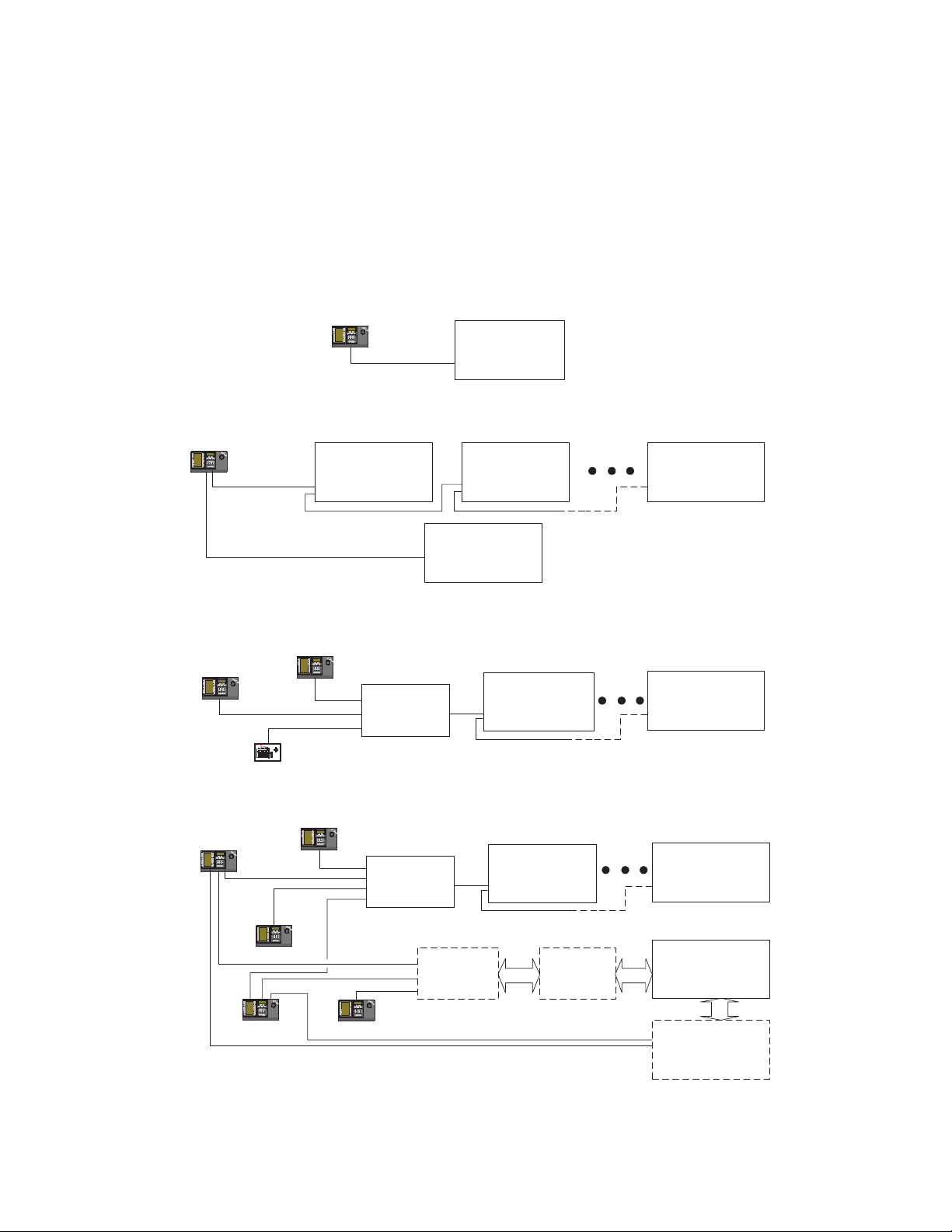
2.1 Determining the IntuiKey System Configuration
Before the IntuiKey is mounted or connected to other system
components, system configuration must be determined.
The IntuiKey is capable of controlling up to thirty (30)
multiplexers/DVRs and one (1) video switcher simultaneously.
Figure 2-1 illustrates basic IntuiKey system configuration with these
devices. If more than one IntuiKey is to be connected to a single
multiplexer or group of daisy-chained multiplexers, a keyboard port
expander must be added. The Allegiant Series of video switchers
have a varying number of keyboard ports depending on model
number. If more than eight keyboards are required on one of the
larger Allegiant Series Switchers, an Allegiant keyboard expander
must be added.
NOTE: Philips offers the following Keyboard Expanders:
•For Use with Allegiant Series Switchers:
LT C 8714 – Keyboard Port Expander
LT C 8715 – Keyboard Expander
•For Use with Divar Series DVRs, or System4
®
Video Multiplexers:
LT C 2604 – Keyboard Port Expander
Please contact your Philips CSI Sales Representative for more
information.
Figure 2-1 Basic IntuiKey System Configurations
KBD-Digital
PHILIPS
MonProd
Shot
Clr
1
3
2
6
4 5
7 8 9
0
RS-485
One IntuiKey to One Device
KBD-Universal
PHILIPS
MonProd
Shot
Clr
1
3
2
6
4 5
7 8 9
0
RS-485
Divar Digital
Video Recorder
# 1
Divar Digital
Video Recorder
Divar Digital
Video Recorder
# 2
Divar Digital
Video Recorder
# 30
KBD-Universal
PHILIPS
MonProd
Shot
Clr
1
3
2
6
4 5
7 8 9
0
LTC 2601/00
KBD-Universal
PHILIPS
MonProd
Shot
Clr
1
3
2
6
4 5
7 8 9
0
KBD-Digital
KBD-Universal
RS-485
ALLPLEX
VCR
APX
B
REC
#
SEQ
PLAY
1 2 3
SET
REC
PLAY
4 5 6
SHOT
7 8 9
AUX+
B
0/10 11 12
AUXSEQ
ACT
13 14 15
16
ALM ( )
ALLPLEX VCR
RS-485
PHILIPS
MonProd
Shot
Clr
1
3
2
6
4 5
7 8 9
0
PHILIPS
MonProd
Shot
Clr
1
3
2
6
4 5
7 8 9
0
RS-485
Allegiant Series
Video Switcher
One IntuiKey to Multiple Devices
KBD-Mux
PHILIPS
MonProd
Shot
Clr
1
3
2
6
4 5
7 8 9
0
LTC 2604
Keyboard
System4
Multiplexer
®
Expander
Multiple Keyboard Models to Multiple System4 Multiplexers
PHILIPS
MonProd
Shot
Clr
1
3
2
KBD-Digital
6
4 5
7 8 9
0
LTC 2604
Keyboard
Divar Digital
Video Recorder
Expander
PHILIPS
RS-485
PHILIPS
MonProd
Shot
Clr
1
3
2
6
4 5
7 8 9
0
Optional
LTC 8714
Expander
Optional
LTC 8715
Expander
KBD-Universal
RS-232
Multiple Keyboards to Multiple Devices
Multiplexer
®
Divar Digital
Video Recorder
Allegiant Series
Video Switcher
Optional ADIM
Digital Recording
System4
System
®
Page 11
12
System power connections must also be considered. Depending
on the distance between the keyboard and devices under control,
an external power supply may be needed according to the
following specifications:
* NOTE: Distances may vary depending on the number of keyboards
connected.
2.2 Mounting the IntuiKey
The IntuiKey LCD displays are readable in all but direct sunlight
conditions. Locate the keyboard on a flat horizontal surface, with
an optimal LCD viewing angle of 0 to 20 degrees from vertical.
Display contrast levels are software-controlled and may be adjusted
via the Keyboard Control Menu (as described in Section 3.4). An
optional rack mount kit may also be used.
2.3 Connecting the IntuiKey
1. Refer to Figure 2-2 for details on the input/output
connections supplied by the IntuiKey Keyboard. Four
connectors are located on the IntuiKey rear panel: (2) RJ-11
connectors, (1) female 9-pin sub-D connector, and a DC
power jack. The RJ-11 connectors are labeled as Allegiant
and MUX/DVR, and the 9-pin sub-D is labeled RS-232
Serial Port.
Figure 2-2 Back Panel Connections of IntuiKey
ATTENTION: To ensure proper system functioning and to
prevent damage to the unit, it is critical that only Allegiant
devices be connected to the Allegiant connector, and
Multiplexer/DVR devices be connected to the MUX/DVR
connector.
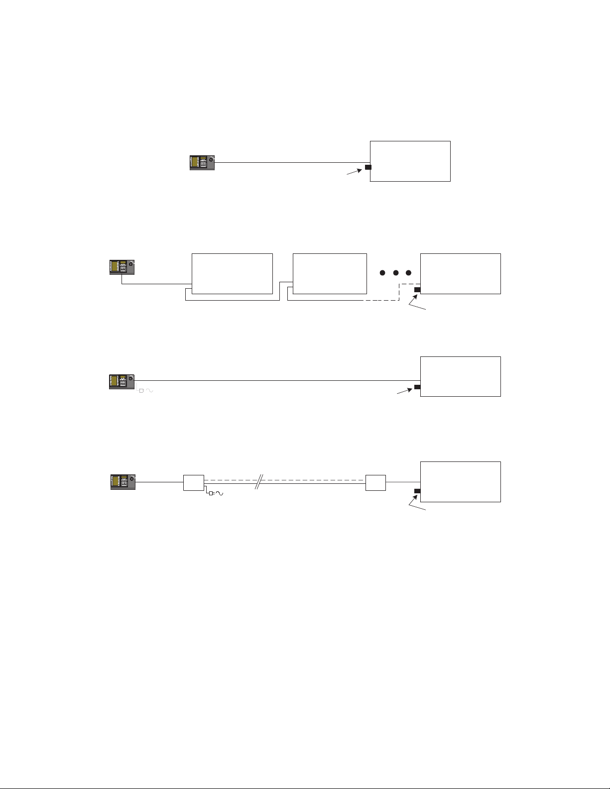
2. Review the configuration options shown in Figure 2-4.
Make the necessary keyboard data and power connections
that are best suited to your system requirements based on
these diagrams. When connecting to Divar DVRs or
System4®Multiplexers, attach the supplied 390 Ohm
terminator to the Out connector on the last device.
NOTE: In systems having multiple Divar DVRs or multiple
System4®Multiplexers, use the front panel controls on the video
devices to assign appropriate address numbers and starting
camera numbers. The IntuiKey will not properly recognize the
video devices if there are conflicting addresses in the system.
3. After power is applied, the keyboard initializes and displays
the following:
Figure 2-3 Initial Power-up Display
4. After a brief pause (or immediately after the Clr button is
pressed), the keyboard will perform a brief search for
connected devices.
NOTE: On initial power-up, factory reset, or firmware upgrade,
the IntuiKey displays a Language Menu. Select the desired
language by pressing the softkey next to the language title. If
additional languages are available, the arrow softkeys at the
bottom of the screen can be used to scroll to a second menu
screen.
Distance from Keyboard Optional Equipment
to Device under Control* Needed
Less than 10 ft (3.5 m) NONE
Between 10 ft (3.5 m) KBD-120PS/KBD-220PS
and 100 ft (30 m) External Power Supply
Greater than 100 ft (30 m) LTC 8557/60(50)
Keyboard Extender
Allegiant
MUX/DVR
MUX / DVR ALLEGIANT 12 VDC RS-232 SERIAL PORT
DC Power
RS-232
Serial Port
KBD – Universal
KBD – Universal
Philips CSI
Copyright 2002
Protocol: .6P
Firmware Ver: x:xx
Bootldr Ver: x:xx
Hardware Ver: x:xx
Press [CLR] key to
Exit
Philips CSI
Firmware Ver: x:xx
Prod Mon
Clr
0
Shot
321
654
987
Page 12
13
IntuiKey
Figure 2-4 Typical Intuikey Connection Options
NOTE 1: Attach the supplied 390 Ohm terminator to the Out connector when using Divar Digital Video Recorders or System4®Multiplexers.
Keyboard
PHILIPS
MonProd
Shot
Clr
1
3
2
6
4 5
7 8 9
0
3m (10 ft) Data/Power Cable
(See Note 1)
IntuiKey Connection Using Supplied Data Cable
Video Device
IntuiKey
Keyboard
PHILIPS
MonProd
Shot
Clr
1
3
2
6
4 5
7 8 9
0
IntuiKey
Keyboard
PHILIPS
MonProd
Shot
Clr
1
3
2
6
4 5
7 8 9
0
Optional Power
PHILIPS
MonProd
Shot
Clr
1
3
2
6
4 5
7 8 9
0
IntuiKey
Keyboard
Multiple Divar Digital Video Recorders or System4 Multiplexers
Video Device Video Device Video Device
Supplied
3m (10 ft)
Data/Power
Cable
Supply
IN
OUT
RS-485
IntuiKey Connection Using Supplied Data Cable
30m (100 ft) LTC 8558/00 Data Cable
IN
OUT
(See Note 1)
IntuiKey Connection Using Optional LTC 8558 Data Cable
Supplied
3m (10 ft)
Data/Power
Cable
LTC 8557
Junction Box
RS-485
User Supplied Shielded
Twisted Pair Cable
Up to 1.5 km (5000 ft)
Supplied
3m (10 ft)
Data Cable
LTC 8557
Junction Box
IntuiKey Connection Using Optional LTC 8557 Remote Hookup Kit
IN
OUT
(See Note 1)
Video Device
Video Device
(See Note 1)
Page 13
14
3OPERATING THE INTUIKEY DIGITAL
KEYBOARD
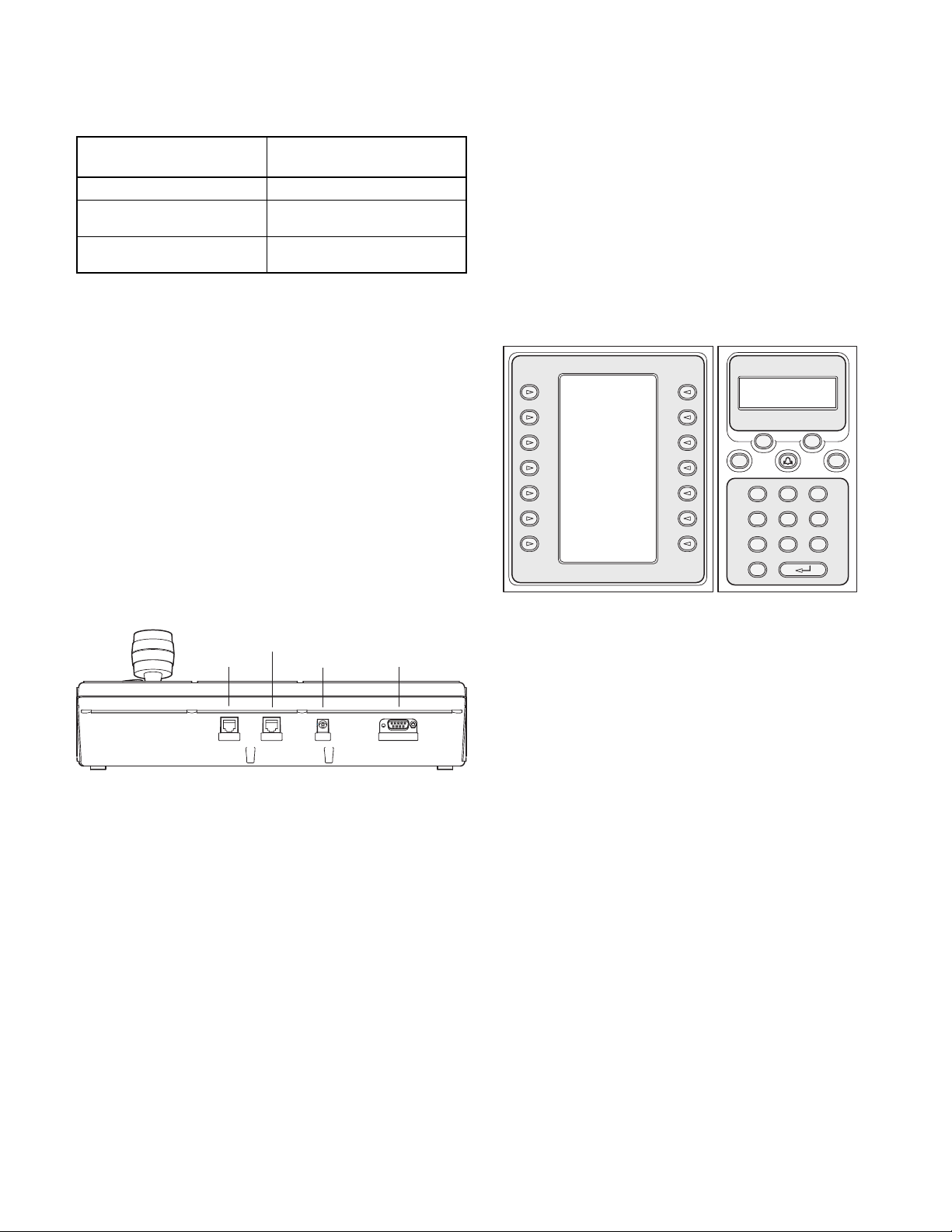
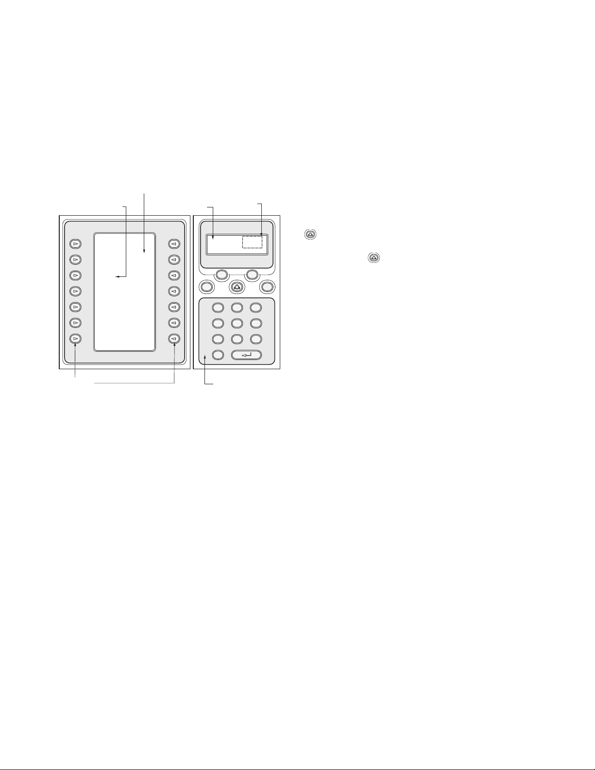
3.1 Learning the IntuiKey Components
Learning the IntuiKey Keyboard components is accomplished
easily by dividing the keyboard into four separate functional areas
as shown in Figure 3-1:
• The Status Display
• The Keypad
• The Softkeys and Softkey Display
•The Joystick
Figure 3-1 IntuiKey Components
3.1.1 The Status Display
The Status Display changes dynamically to display pertinent
information about the keyboard’s present mode of operation.
Typically, its information conveys one of two keyboard operating
modes: Normal Mode or Error Code.
In Normal Mode, the status display provides data pertaining to
the present device under control (e.g. monitor number, camera
number, device under control status, etc.). Common elements in
the display for all devices are a product indicator centered on the
bottom line of the display and one or more numeric entry cells.
Each numeric entry cell has a title that describes what the number
represents.
When a user operation results in an error, the status display
changes to Error Code (see Section 4.3 for Allegiant Error
Messages, Section 5.6 for Divar Error Messages, and Section 6.3
for Mux Error Messages). The display shows the error number, a
short description of the error, and the present device under
control.
The display reverts to Normal Mode either automatically in two
seconds (on its own) or when CLR is pressed.
3.1.2 The Keypad
The Keypad includes the five function buttons (located directly
below the status display), as well as the numeric keypad.
PROD displays the keyboard’s Product Selection Menu. This
function key (in conjunction with the Softkeys/Softkey Display)
selects the device under the control of the keyboard. The Product
Selection menu also provides access to the Keyboard Control
Menu.
MON functioning depends on the IntuiKey Model and device
under control. For KBD-Universal keyboards, MON allows entry
of a Monitor Number when controlling an Allegiant Switcher.
When controlling a DVR or multiplexer, MON toggles between
Monitors A and B.
CLR clears any numeric entry and the display reverts to Normal
Mode.
provides acknowledgement of an external alarm/alert/action
condition. When this condition is detected, an audible alarm is
enabled, and the key flashes red. The key then functions
differently depending on the device presently under keyboard
control.
NOTE: Refer to Section 3.3 for additional information on
alarm/alert/action indication and acknowledgement.
SHOT allows selection of camera pre-positions and is also used to
assign softkey display screen numbers. Pressing SHOT twice
enters the preposition programming entry mode. If SHOT is
pressed twice inadvertently, press SHOT again to return to the
pre-position selection mode.
The Numeric Keypad allows numeric entry (shown in the status
display) as required by the present function. Note that the default
state of the Keypad is camera entry (i.e. pressing a numeric key
places that number in the status display under the camera title).
3.1.3 The Softkeys and the Softkey Display
The Softkeys and Softkey Display allow easy and flexible control
and programming of system devices under keyboard control.
The Softkey Buttons are located on either side of the softkey
display. Each softkey may have a special descriptor associated with
it that consists of up to three lines of ten characters. Pressing a
softkey initiates the action described by the associated text. The
actual on-screen display may vary depending on the model being
controlled.
The Softkey Display associates commands with the softkey
buttons. The commands shown in the display changes depending
on the operational mode of the keyboard and previous softkey
selections. Note that the softkey display initially shows a default
menu tailored to the device under control. This initial menu
contains softkey functions that represent commonly used
commands, as well as keys that represent links to other
command menus.
SoftKey Display
SoftKey Descriptor
Status Display
Numeric
Entry Cell
Exit
^ Up Zoom
< Left Right >
v Down
SoftKeys
Monitor Camera
1 1
Prod Mon
Clr
0
Numeric Keypad
MUX/DVR
Shot
321
654
987
Page 14

3.1.4 The Joystick
The IntuiKey Joystick provides two levels of system functionality:
control of pan/tilt/zoom for an external camera or navigating the
on-screen programming menus of the Allegiant Video Switchers,
AutoDome®Series Cameras and other devices.
Moving the joystick in one of eight directions provides pan/tilt
control of appropriately equipped cameras. Rotating the knob in
either a clockwise or counterclockwise direction provides lens
zoom control.
Focus and Iris Control, located above and to the right of the
joystick, are rocker-style buttons that provide keyboard control of
camera lens focus (near/far) and camera iris function (open/close).
3.2 Navigating the System with the IntuiKey
Keyboard
Learning basic navigation techniques with the IntuiKey ensures
readiness for control of the system devices. The following
procedures are general in nature and may be applied to the
control of various system devices/operating modes.
3.2.1 General Guidelines for Navigating the IntuiKey Menus
The following keys are important for entering and exiting the
IntuiKey programming/control menus:
• EXIT – This softkey command is located in the upper left
corner of each softkey menu. Use this key to move back
one level in the menu structure (complete menu diagrams
are provided in Appendix A at the back of this manual).
• PROD – Press PROD at any time to return directly to the
Main Product Selection menu.
• CLR – Press CLR to clear any numeric entry and revert the
display to Normal Mode.
3.2.2 The Product Selection Menu
The Product Selection menu lists the devices that are in
communication with the IntuiKey. Up to 12 devices can be shown on
a single screen. If more than 12 devices are connected, the arrow
softkeys at the bottom of the screen can be used to scroll through the
additional menu(s).
The softkey to enter the Keyboard Control menu can always be found
at the very end of the device listings.
Figure 3-2 Main Product Selection Menu
IMPORTANT: When the IntuiKey is first connected up to a device,
or whenever a new video device is added to an existing system, enter
the Product Selection menu and press the PROD key. The keyboard
will initiate a scan of the communication lines and update the list of
devices connected to it.
If communication is ever lost with an existing device, the product name
display will indicate an Off_Line condition. After communication
with the device is restored, this message will disappear.
For multiplexers, the device address number will be shown. For DVRs,
the DVR address number, its name, and the starting camera offset
number will be displayed.
3.2.3 Selecting a Device for Control
1. Press the PROD button to put the keyboard in the Product
Selection Mode. The softkey display shows the Product Selection
menu (refer to Figure 3-2).
2. Press the desired softkey button adjacent to the desired product
name in the display. Upon selection of a system device to be
controlled, the keyboard indicates what product it is controlling
by displaying its name (up to 10 characters maximum) at the
bottom of the status display. The softkey display menu also
changes to the top level menu associated with the selected device.
3.2.4 Easy Switching Between Devices
Pressing and holding the PROD key for longer than 1 second while
using a DVR or multiplexer enters the device address selection mode.
Entering the address of a device will cause the keyboard to switch to
that device’s main menu. If the device address does not exist, an error
message will result, and no change will occur.
3.2.5 Using the Keypad for Numeric Entry (Camera Control)
1. Press a desired numeric key to place the number in the status
display under the camera title.
2. Note that additional key entries add digits to the RIGHT side
of the camera number. If more than the maximum number of
digits allowed for the specific entry is entered, the leftmost
digit is lost, and all other digits promoted.
3. Leading zeros may be entered but are not required.
4. Press ENTER to complete numeric entry.
3.2.6 Using the Quick Selection Softscreen Feature
The IntuiKey softkey display screens can be assigned a reference
number which can then be recalled to quickly return to the
desired screen.
1. To assign a number to a softkey display screen, first navigate
to the desired screen. Simultaneously press the digit 0 and
ENTER to enter the softkey screen programming mode. Press
SHOT followed by the single digit (0 to 9) that you want to
assign to this screen.
2. To quickly jump to a previously programmed softkey display
screen, simultaneously press the digit 0 and ENTER. Press
the desired softkey display screen number.
NOTE: Ten (10) softkey numbers are available within a single
product category. Softkey screen numbers can only jump between
screens within the same product category. If an existing softkey
screen number is assigned to a new softkey screen, the old one is
no longer valid. Assignments remain even if power is lost.
15
Allegiant
ADIM
DVR 1
Unit A
1
DVR 2
Unit B
17
DVR 3
Unit C
33
DVR 4
Unit D
49
DVR 5
Unit E
65
DVR 7
Unit F
97
DVR 8
Unit G
113
DVR 9
Unit H
129
DVR 10
Unit J
145
DVR 11
Unit K
161
Page 15

16
3.3 Alarm/Alert/Action Indication
When the IntuiKey detects that an alarm/alert/action condition
has occurred on the presently controlled device, the key
flashes red and an audible tone is heard. During alarm responses,
Divar DVRs and System4®multiplexers will also show special
icons to represent the different types of alarm conditions. Contact
type alarm conditions will be represented by a icon, and
action alarm conditions will be represented by a icon.
If the alert occurs on a device that is not presently under control,
the product indicator (in the status display) alternates between the
present product designator and the alarmed product, with the text
ALERT added. The present product is displayed for two seconds,
while the alarmed product is displayed for 0.5 seconds.
3.4 Configuring the IntuiKey Keyboard
The IntuiKey Keyboard plug and play design allows operation to
begin as soon as the keyboard is connected to system
components. However, if you desire to review the default settings,
or wish to change any of these settings, refer to the following
information and procedures for the Keyboard Control Mode.
3.4.1 Accessing the Keyboard Control Menu
1. Press PROD to view the Product Selection menu
(see Figure 3-2).
2. Press the softkey labeled Keyboard Control. The Keyboard
Control softkey can always be found at the very end of the
device listings.
3. The Softkey Display shows the Keyboard Control main
menu (see Figure 3-3). A review of the Keyboard Control
menu options follows.
Figure 3-3 Keyboard Control Menu
3.4.2 Keyboard Control Menu Options
Exit
Reverts to the Product Selection menu.
Factory Reset
Resets the keyboard to the following states:
Product Selected NONE
Key Click ON
Display Inverse Normal (black on white)
Mux Destination Addr 1
Softkey Contrast 9
Status Display Contrast 6
Mux User Level No Access
Language NONE
Allegiant Baud 9600
Not Used
Language Select
For selection of the display language. Choose from the following
languages: English, French, Spanish, Italian, Dutch, and German.
Pressing the next or previous arrow jumps between this menu and
the Polish and Portuguese option menu.
Keyboard Test
Displays a keyboard test screen on the softkey display. Press
ENTER to exit the keyboard test mode. As each key is
pressed, an indicator displays on the screen. If the joystick is
moved, its present variable speed value is displayed. Pan and
Tilt ranges from 0 to 15; Zoom ranges from 0 to 7.
LCD Test
Different patterns are displayed on the softkey display, and
the alarm LED flashes. Each pattern displays for
approximately two (2) seconds.
Joystick Autocal
Auto-calibrates the joystick (allow the joystick to self-center,
then press ENTER). The softkey display then indicates New
Values Saved.
Not Used
Firmware Upgrade
Places the keyboard into a password-protected mode that
allows upgrade of the internal software via serial connection
to a host computer. See Appendix C for details on entering
passwords.
Not Used
Allegiant Baud
This password-protected option is used to set the baud rate
of the keyboard’s Allegiant port. In most cases, this setting
should not be changed unless directed by the factory. The
settings must match in both the keyboard and the Allegiant.
Two rates are available, 9600 (default) and 19,200. The
current setting is displayed on the menu screen.
Contrast Adjust
Displays the Contrast Adjust menu which provides two
adjustment scales: one for the softkey display, and one for the
status display. Control each adjustment scale with the adjacent
softkey buttons (as indicated by the arrows in the menu).
Generally, the buttons to the right of each scale decrease the
contrast (make the display lighter), while the buttons to the
left increase the contrast (make the display darker). The
indicator on the scale is incremented (moved) one step for
each press of the softkey. The indicator wraps around when
either limit is reached. When the desired contrast level is
reached, press ENTER to exit the submenu and store the
values. Press CLR at any time to reset the contrast to the
presently stored value. Pressing MON + CLR (simultaneously,
at any time while using the keyboard) resets the contrast to the
center position of the scale.
NOTE: It is possible to adjust the contrast to a level where
the text cannot be seen. If this happens, simply continue
pressing the softkey until the text reappears OR press CLR
to restore the display to the presently stored values.
Key click On/Off
Toggles between audible sound at each key click and no
sound at each click. Upon pressing the key, the softkey
descriptor indicates whether key click is on or off.
Display Inverse
Toggles the display between black-on-white display or whiteon-black display. Upon pressing the key, the softkey descriptor
indicates whether display inverse is on or off.
Exit
Factory Firmware
Reset Upgrade
Allegiant
Language
Baud
Select
9600
Keyboard Contrast
Test Adjust
LCD Key Click
Test On/Off
Joystick Display
Auto Cal. Inverse
Normal
1
2
3
4
5
6
7
8
9
10
11
12
13
14
Page 16

17
4 CONTROLLING ALLEGIANT®SERIES
VIDEO SWITCHERS
NOTE: This section applies to KBD-Universal Model ONLY.
4.1 The Allegiant Main Control Menu
4.1.1 Accessing the Allegiant Main Control Menu
1. Press PROD to put the keyboard in Product Selection Mode.
The Product Selection menu appears in the softkey display.
2. Press the Allegiant or ADIM softkey button, and observe that
the status display shows the Allegiant mode.
Figure 4-1 Status Display in Allegiant Mode
IMPORTANT NOTE REGARDING USER LOG-ON:
Depending on the setting of the Allegiant Switcher, it may be
necessary to perform a log-on procedure to gain control of the
switcher (i.e. to gain access to the Allegiant Main Control
menu).
• If log-on information is required, the status display
requests a USER NUMBER. Enter the number using
the keypad, and press ENTER.
• The status display requests a PASSWORD. Enter the
password using the keypad, and press ENTER.
• If an invalid user number or password is entered, the
request for log-on is redisplayed.
• Following successful user log-on, the softkey display
shows the Allegiant Main Control menu as in
Figure 4-2.
• If user log-on is NOT required, the softkey display
shows USER LOGGED ON (briefly), and then
displays the Allegiant Main Control menu.
Figure 4-2 Allegiant Main Control Menu
4.2 Programming/Controlling Allegiant Functions
4.2.1 Allegiant Main Control Menu Command Descriptions
The Allegiant Main Control menu, displayed on the softkey
display, uses the softkey buttons to execute commands or to gain
access to other submenus for additional programming/configuration.
Detailed command descriptions follow. Refer to the Allegiant
Switcher Instruction Book for additional information.
Exit
Exits one menu and reverts to the main menu for the
particular function being programmed/controlled.
Device Lockout
Accesses a softkey menu, allowing the locking/unlocking of
specified cameras and monitors.
Figure 4-3 Device Lockout Menu
User
Exit Log Off
Device Command
Lockout Script
Program Camera
Sequence Control
Alarm User
Control Functions
Load ADIM
Sequence Controls
Hold Start
Sequence Sequence
< Previous Next >
< SequenceSequence >
< Step Step >
Exit
Monitor Monitor
Lock Unlock
Remote Remote
Lock Unlock
Monitor Camera
123 1234
Allegiant
1
2
Page 17

a. Monitor Lock/Unlock:
•If the monitor to be locked/unlocked is not the present
monitor, press MON on the keypad. Then enter the
monitor number, followed by ENTER.
•Press the monitor Lock/Unlock softkey.
•If the monitor is locked, the display shows an ML on the
monitor’s on-screen status display, indicating that the
monitor is locked. If the monitor is unlocked, ML is
removed.
b. Remote Lock/Unlock:
• If the Camera to be locked/unlocked is not the present
camera, enter the camera number followed by ENTER.
• Press the Remote Lock/Unlock softkey.
• If the camera is locked, the display shows an RL in the
monitor’s on-screen status display, indicating that the
remote device is locked. If the camera is unlocked, RL is
removed.
To leave the device lockout menu, press EXIT.
Alarm Control
Alarm commands control the system’s automatic video
switching capabilities in response to alarm signals activated in
the Allegiant system. The camera activated by an alarm is
normally the same as the alarm number, but this relationship
can be changed using the optional LTC 8059/00 Master
Control Software for Windows®or the optional LTC 8850/00
Graphical User Interface software package. These optional
software packages even permit up to four cameras to be
alarmed by a single alarm input.
Figure 4-4 Alarm Control Menu
a. Arm/Disarm Alarm:
To arm/disarm an individual alarm on the monitor
currently controlled by the keyboard:
• Press the Arm/Disarm Alarm softkey. The status
display changes to the following:
Figure 4-5
• Enter the alarm number to be armed/disarmed, using
the numeric keypad.
• Press ENTER.
b. Arm/Disarm All Alarms:
To arm/disarm all alarms on the currently controlled
monitor, simply press the Arm/Disarm All Alarms softkey.
c. Arm Monitor:
Press the Arm Monitor softkey to arm the monitor
currently controlled by the keyboard, permitting cameras for
armed alarms to automatically display when an alarm occurs.
NOTE: Alarm video appears on a given monitor only if
the monitor is armed and the alarm is armed for that
monitor. The on-screen monitor status display shows MA
(Monitor Armed).
d. Disarm Monitor:
Pressing the Disarm Monitor softkey disarms the monitor
currently controlled by the keyboard, thus prohibiting the
monitor from responding to alarms.
Program Sequence
Changes the softkey display and requests entry of a sequence
number to program. The status display shows the following:
Figure 4-6
Exit
Arm Disarm
Alarm Alarm
Arm Disarm
All All
Alarms Alarms
Arm Disarm
Monitor Monitor
Alarm#
----
Allegiant
Program Sequence
---
Allegiant
18
3
4
Page 18

19
Load Sequence
Enables the loading of a previously programmed sequence.
• Press the Load Sequence softkey. The status display shows
the following:
Figure 4-8
• Enter the sequence number, then press ENTER.
• To unload a sequence, stop the sequence (if necessary),
press the Load Sequence softkey, then press ENTER.
• Use CLR to clear an incorrectly entered number.
Hold Sequence
Stops a running sequence.
Previous Sequence Step
Sets the sequence direction to run in reverse. If the sequence
is already running in reverse, pressing this button executes
the previous sequence step immediately. Holding the key
causes the sequence to run in fast reverse mode, at
approximately two steps per second.
User Log-off
Used to LOG OFF the Allegiant Switcher.
• Press the User Log OFF softkey.
• The softkey display shows the following:
Figure 4-9
• Press CLR to clear the pending log-off. Press ENTER to
complete the log-off process. The softkey display reverts to
displaying only USER LOG ON, and the status display
changes back to the default mode (i.e. camera and monitor
numbers replaced with dashes). This mode times out in
approximately two seconds and reverts to the previous menu.
Upon entry of a sequence number followed by ENTER, the
softkey display changes to the following menu to support
sequence programming:
Figure 4-7 Program Sequence Menu
Sequence programming is displayed on the controlled
monitor screen.
a. Exit/Save
Saves the present sequence and exits the Program
Sequence menu.
b. Previous Step
Displays the previous sequence step on the OSD (onscreen display) and allows editing.
c. Next Step
Displays the next sequence step on the OSD and allows
editing.
d. Exit/Run
Saves the present sequence, loads it, runs it, and exits the
Program Sequence menu.
e. Insert Step
Inserts a step before the sequence step presently displayed
on the OSD.
f. Delete Current Step
Deletes the current step. Note that if this is done on the
first step of a single-step sequence, the sequence is erased,
and the programming mode is automatically exited.
g. Delete from Here to End
Deletes all remaining steps after the step presently
displayed on the OSD.
Exit/ Exit/
Save Run
Previous Insert
Step Step
Next Delete
Step Current
Step
Delete
from Here
to End
Allegiant
User Log OFF
Press:
[Enter] to log off
[Clr] to Exit
Sequence?
---
Allegiant
5
6
7
8
Page 19

Command Script
Accesses a series of menus, allowing execution of Allegiant
script commands. Refer to the Allegiant Instruction
Manual for additional information.
a. Run Command Script:
This function allows the user to execute * STAR
commands from the keyboard. The Allegiant supports
over 150,000 commands. Press the Run Script softkey to
display the following softkey menu:
Figure 4-10a
b. Executing Command Scripts:
Run a Command Script in one of two ways. Either press
the Run Script softkey (and enter the script number on
the keypad) OR press the
* key for the STAR only
command (i.e. Allegiant command script, 0000).
NOTE: The Command Script menu can be customized
with specific scripts and submenus using the optional
IntuiKey PC software package. Refer to the
documentation included with the software for more
specific instructions.
Camera Control
Displays the camera control softkey menu, allowing the entry
of various camera control commands. Refer to Appendix B
at the back of this manual for details on the camera
commands. Access to certain AutoDome menus and
commands may be prohibited by security features within the
camera. Refer to Appendix D for more information.
User Functions
Accesses a series of 5 menus (User Function Menu A
through User Function Menu E, see Figure 4-11), allowing
single-key selection of all available Allegiant user functions.
Each of the 5 menus contain the following common softkeys:
a. Exit (upper left):
Completes any pending user function and exits to the
Allegiant Main Control menu.
b. Previous Menu (lower left):
Displays the previous menu in this series of 5. If the
current display is the first menu, Previous Menu displays
the last menu.
c. Enter User Command (upper right):
This function alleviates scrolling through menus. When
pressed, this key prompts for the 2 digit Allegiant User
Command number. Familiarity with Allegiant User
Commands and the 2 digit command number is required.
Refer to Figure 4-12 for a cross-reference of all Allegiant
User Commands and their respective 2 digit function
numbers. These function numbers can also be found in
your Allegiant User Manual or on the Allegiant Quick
Reference card.
d. Next Menu (lower right):
Displays the next menu in this series of 5. If the current
display is the last menu, Next Menu displays the first
menu.
Figure 4-12 on the following page shows the menu
location and the associated 2 digit cross reference. For
details on the functionality of these user functions, refer
to the Allegiant Matrix Switcher User Manual.
ADIM Controls
Visible only when keyboard is being used with the ADIM
integrated Allegiant/Hi-Q
™ digital recording system).
This softkey accesses the ADIM DVR control softkey menu:
Figure 4-10b
Refer to instructions provided with the ADIM system for details
on these functions.
Start Sequence
Starts a sequence.
Next Sequence Step
Sets the sequence direction to run forward. If a sequence is
already running forward, pressing this button executes the
next sequence step immediately. Holding the key causes the
sequence to run in fast forward mode at approximately two
steps per second.
9
Exit
Run
Script
*
Star
Exit Play/
Search
Quad Stop
OSD Zoom
Frame
Advance
Alarm
Pause
List
1-Touch
Menu
Alarm
Alarm
Okay
Clear
20
12
10
11
13
14
Page 20

21
ABCDE
Menu Softkey Function Description Allegiant User Access Level
Function #
A2 Display User #/Priority 33 Any
A3 Change User Password 10 Any *
A9 Show Keyboard Port # 2 Any
A10 Keyboard Audio 3 Any
B2 Adjust Display Position 4 1– 7
B3 Brightness/Status Selection 5 1– 7
B4 Display Options 6 1– 7
B5 Set Time 7 1– 7
B6 Set Date 8 1– 7
B9 All Display Position 24 1– 7
B10 All Display Brightness/Status 25 1– 7
B11 All Display Option 26 1– 7
B13 User Function Index 99 Any
C2 Set Camera ID Title 9 1
C3 Set Monitor ID Title 17 1
C4 Display CPU Version 23 Any
C5 Reset System 15 1 *
C6 Vertical Sync Adjust 40 1 *
C9 Default RS-232 29 1 *
C10 Console RS-232 (Select Controller RS-232 - 8900) 30 1 *
C11 Printer RS-232 (Select Console RS-232 - 8900) 31 1 *
C12 Alarm RS-232 32 1 *
C13 User Function Index 99 Any
D2 Select Time/Date Format 11 1
D3 Default Monitor Overlays 12 1
D4 Select Alarm Response 19 1 *
D5 Set Alarm Monitor Type 21 1 *
D6 Time Event Enable/Disable 16 1
D9 Select Keyboard Login 27 1 *
D10 Select Console Login 28 1 *
D11 Print Configuration Tables 13 1
D12 Print Sequence Tables 18 1
D13 User Function Index 99 Any
E2 Select Control Code Format 22 1 *
E3 Select Printer Verbosity 20 1 *
E4 Printer Port Mode 38 1
E5 Select Crosspoint Data 36 1
E9 Camera Indicator 34 1
E10 Set Controllable Cameras 35 1
E11 R/D Address Mode 37 1 *
E12 Cache Remote Cameras 40 1 *
E13 User Function Index 99 Any
Enter
Exit User
Command
Display Show
User #/ Keyboard
Priority Port #
Change
User Allegiant
Password Audio
< Previous Next >
< Menu Menu >
< >
Enter
Exit User
Command
Adjust All
Display Display
Position Position
Brightness All
Status Display
Selection Brightness
Display All
Option Display
Option
Set
Time
Set User
Date Function
Index
< Previous Next >
< Menu Menu >
<>
Enter
Exit User
Command
Set Default
Camera RS232
ID
Set Console
Monitor RS232
ID
Display Printer
CPU RS232
Version
Reset Alarm
System RS232
Vertical User
Sync Function
Adjust Index
< Previous Next >
< Menu Menu >
<>
Enter
Exit User
Command
Select Select
Time/Date Keyboard
Format Log In
Default Select
Monitor Console
Overlays Log In
Select Print
Alarm Config.
Response Tables
Set Alarm Print
Monitor Sequence
Type
Time Event User
Enable/ Function
Disable Index
< Previous Next >
< Menu Menu >
<>
Enter
Exit User
Command
Select Camera
Control Indicator
Code FMT
Select Set
Printer Controllable
Verbosity Cameras
Printer R/D
Port Address
Mode Mode
Select Cache
Crosspnt. Remote
Data Cameras
User
Function
Index
< Previous Next >
< Menu Menu >
<>
Figure 4-11 Allegiant User Functions Menu
Figure 4-12 Softkey to User Function Cross-reference
Page 21

22
Error Name Description
Error 01 Invalid Camera Request The camera number entered from the keyboard does not exist. If
using the optional LTC 8059/00 Master Control Software or the
LTC 8850/00 Graphical User Interface Software, ensure that the
number exists in the Camera Identification table. Download the
table to be sure.
Error 02 Invalid Monitor Request The monitor number entered from the keyboard does not exist.
Error 03 Remote Device Locked The remote device requested cannot be controlled, because it is locked
by User# by a user with equal or higher priority. Check with the other users or
request that a higher priority user unlock the remote device.
Error 04 Monitor Locked by User# The monitor requested cannot be accessed, because it is locked by a
user with equal or higher priority. Check with the other users or
request that a higher priority user unlock the monitor.
Error 05 Remote Device Access Restricted Remote locked out by Remote Lock Out table.
Error 06 Monitor Access Restricted Monitor locked out by Monitor Lock Out table.
Error 10 Access Denied A function was requested for which the user priority is too low. Only a
Priority 2 user or a supervisor with Priority 1 may access this function.
Error 11 Access Denied A function was requested for which the user priority is too low. Only a
supervisor with Priority 1 may access this function.
Error 15 Invalid User Function The function number requested from the keyboard is invalid. Refer to
the User Function table for a listing of valid user function numbers.
Error 20 Acknowledge Denied The ACKNOWLEDGE button was pressed by a user without the
authority to acknowledge alarms.
Error 21 Incorrect Acknowledge In order to properly acknowledge an alarm event, the keyboard must be
switched to a monitor that is displaying the alarms.
Error 22 Acknowledge Disabled Alarms on this monitor cannot be acknowledged, because that
capability has been disabled by the system programmer.
Error 23 Camera Not in alarm The camera displayed on the monitor is not an alarm video; only
alarm-generated video can be acknowledged.
Error 24 Keyboard Not Enabled This keyboard may not acknowledge alarm video on this
for Acknowledge monitor; it has been disabled by the system programmer.
Error 25 Alarm Switcher Running Alarm video may only be acknowledged if the alarm switcher is not
running; press HOLD to stop the switcher.
Error 50 SEQUENCE Not Available The user attempted to load a switcher sequence that does not exist.
This is a good way to determine, from the keyboard, which sequence
numbers are unused when desiring to add one. A request was made to
load an ABSOLUTE type sequence, without the keyboard being on
one of the monitors in that sequence. Because inadvertent loading of
monitors should be avoided, the user is required to switch his keyboard
to one of the monitors used by the sequence.The PROGRAM mode
may be used to review which monitors are used in the sequence.
Error 52 SEQUENCE Request A request was made to load a RELATIVE type sequence on a monitor
number that is too high; the monitors used by the sequence would extend
past the highest monitor.Try switching to a lower monitor number before
loading the sequence.
4.3 Allegiant Error Messages
Page 22

23
Error Name Description
Error 53 Switcher Empty The user has attempted to control a sequence using the NEXT,
PREV, RUN, or HOLD keys, without there being a sequence loaded.
Error 55 SEQUENCE Priority The switcher sequence being requested or cleared requires monitors
that are in use by a user of equal or higher priority. Contact a user with
higher priority or have the system administrator clear the monitors in
question.
Error 56 SEQUENCE Request The user has attempted to load a sequence that is being edited in the
PROGRAM mode. Once editing is complete, the sequence may be
loaded.
Error 58 SEQUENCE Request The sequence being requested is a relative sequence, and the user is
only permitted access to absolute sequences.
Error 60 PROGRAM Request The user has attempted to program a sequence that is currently
running.The sequence must first be stopped before any editing can be
performed.
Error 62 PROGRAM Request The user has attempted to program a new sequence when the
sequence memory space has been depleted. Delete unused sequences,
then program the new sequence.
Error 63 PROGRAM Request Another user is already programming a sequence on this monitor.
Error 70 Monitor Not Allocated to Group This monitor cannot be used for alarm operations; it has not been
designated as alarm-capable by the system programmer.
Error 71 Step Monitor Required A group of alarm monitors may not have an armed Review (display)
monitor without having armed Step (sequence) monitors.
Error 78 Must Enter Alarm Number A specific alarm number must be entered when arming or disarming
an alarm.
Error 80 Trunk Not Available An attempt was made to access a remote camera connected to a
satellite system, but no unused trunk lines are currently available.
Error 81 Satellite Trunk Seized The camera currently viewed has changed because an operator with a
higher priority has selected a different camera that seized the trunk line
from the satellite.
Error 89 Internal Stack Error A stack overflow within the system has occurred. Report this to the
manufacturer.
Error 90 Keyboard Entry Undefined The keyboard entry is not defined. Check the appropriate section of
the instruction manual for the desired operation and try again.
Error 92 Keyboard Entry Out of Range The data entered for a valid command was not in the permissible range.
Check the appropriate section of the instruction manual for acceptable
ranges for the command in question and try again.
Error 94 Keyboard Entry Invalid An invalid character was received from the keyboard. Usually this
indicates a communications error. Verify that the keyboard-to-system
cable is not producing an intermittent connection.
Error 95 Keyboard Entry Incomplete The control sequence sent from the keyboard was incomplete. Usually
this indicates a communications error. Verify that the keyboard-tosystem cable is not producing an intermittent connection.
Error 96 * (STAR) Undefined The * key has been pressed, but there is no definition for this button.
Error 100 DVR in Use The DVR is not available because it is currently in use by another
operator.
Page 23

24
Error Name Description
Error 101 Camera Not Found The camera currently selected is not configured for use on
the ADIM system.
Error 102 ADIM Communication Error The IntuiKey keyboard is unable to communicate with the ADIM system
software.Verify that the ADIM software is configured correctly and that
cable connections are intact.
Error 103 ADIM General Error The IntuiKey keyboard has received an error notification from the
ADIM system software. Please review the log files on the ADIM PC
to determine the exact nature of the problem.
Error 104 ADIM Mode Conflict Error The IntuiKey keyboard has received conflicting status information from
the ADIM system. Power the keyboard off/on to correct.
Error 128 No Communications The keyboard cannot communicate with the Allegiant.
4.4 ADIM Error Messages
Page 24
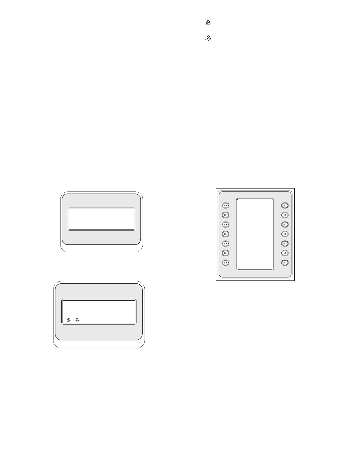
25
5 CONTROLLING Divar SERIES
DIGITAL VIDEO RECORDERS
NOTE: This section applies to KBD-Universal and
KBD-Digital Models.
5.1 The Divar Main Control Menu
5.1.1 Accessing the Divar Main Control Menu
1. Press PROD to put the keyboard in the
Product Selection Mode. The softkey display shows the
Product Selection Menu. Depending on the number of
DVRs that are connected to the IntuiKey, the list may
show a single device name or up to 32 device names
spanning 3 menu screens.
2. Press the softkey button adjacent to the desired DVR
device name in the display. The softkey display menu
will change to the top level menu associated with the
device.
NOTE: If you are already in a product sub-menu, and
multiple products are connected to the IntuiKey, the
keyboard provides a means for easy switching between the
devices. Press and hold the PROD key for longer than
1 second to enter the device address selection mode. The
status display will change to display the following:
Enter the address of the desired device to make the
keyboard immediately switch to that device’s main menu.
3. The status display shows the DVR mode display.
Figure 5-1 Status Display in Divar Mode
The DVR mode is shown on the keyboard status display
and provides the following indicators:
• SEQ – Indicates that the DVR is running a sequence.
• MONA/B – Indicates which DVR monitor is
currently under control. It toggles between MONA
and MONB for each press of the MON key.
NOTE: Keyboard access to MONB must be enabled
within the Divar menus. See Divar manual for details.
• – Indicates that the DVR is in an ACTION
alarm mode.
• – Indicates that the DVR is in a contact
activated alarm mode.
• REC – Indicates that the DVR is currently recording.
• PLAY – Indicates that the DVR is in a replay mode.
• ZOOM – Indicates that the DVR is displaying a
zoomed image.
• ALM xx – Indicates that a device connected to the
IntuiKey with address number xx is currently in
alarm. The IntuiKey’s alarm button will light and the
keyboard will begin to beep.
NOTE: While in DVR Control Code, the product
title continuously displays the programmed device name.
The numeric entry field is used to enter numeric values
needed to control the DVR (i.e. camera number,
DVR number, shot number, etc.). Above the numeric entry
field is a title displaying the DVR’s current mode (i.e.
cameo, camera entry, menu mode, or numeric entry).
4. The softkey display shows the DVR Main Control
menu.
Figure 5-2 Divar DVR Main Control Menu
5.2 Programming/Controlling DVR Functions
5.2.1 The DVR Main Control Menu
The DVR Main Control menu uses softkey buttons to execute
commands or to gain access to other submenus for additional
programming/configuration.
Detailed command descriptions follow. Refer to the Divar
Instruction Book for additional information.
1. Exit
Exits one menu and returns to the main menu for the
particular function being programmed.
2. Full
Select Full Screen Camera Mode by pressing the Full
Screen softkey. The camera currently selected by the
keyboard will be displayed in full screen on the
monitor.
Address
__
DVR
Rec Camera
Seq Play
12
MONA Zoom
ALM 13 DVR#01
Exit
Full
Screen
Quad
Screen
Multi
Screen
Select
Cameo
Segment
Sequence
Zoom
Search
Play
Live
Freeze
Instant
Play
Camera
Control
DVR
Control
Page 25

26
3. Quad Screen
Divides the screen into four separate areas. Enable
Quad Screen Mode by pressing the Quad Screen key
once. Pressing the key additional times cycles through
available viewing configurations.
4. Multi Screen
Enables multiscreen displays. The capabilities and user
setup of the DVR model under control determine the
available configurations.
NOTE: Pressing the Multiscreen softkey multiple times
cycles through the possible selections.
5. Select Cameo Segment
When in Multi or Quad Mode, the screen area where a
camera is displayed is called a cameo. Press the Cameo
softkey to enter the cameo selection mode. In this
mode, the joystick is used to select which cameo window
will be under control of the keyboard. Entering a
number into the keyboard while in this mode will cause
the camera to appear in the currently selected cameo
window. Cameras may be assigned to any selected
cameo, and may be changed as often as required. The
Intuikey’s numeric entry field title will change to Cameo
while the DVR is in this mode. Press the Cameo
softkey again to exit the mode.
6. Sequence
Runs a previously programmed camera sequence.
7. Zoom
Press the Zoom softkey to enlarge the active camera
display. The keyboard will change to the following
submenu for control of the zoom functions:
Figure 5-3 Zoom Menu
NOTE: Different levels of the zoom function (e.g. X2,
X4, normal) are available by repeatedly pressing the Zoom
softkey.
If Zoom softkey is pressed while in multi-screen mode, the
currently selected camera will be changed to full screen
view.
8. Search
Places the DVR into the on-screen search mode and
accesses a DVR softscreen menu allowing selection of
various search criteria. Refer to Section 5.2.2 for details
on menu functions and controls.
9. Play
Activates DVR playback mode and displays the PLAY
indicator in the IntuiKey status display. Press the
softkey again to cancel the playback mode.
10.Live
Pressing the Live softkey will place the DVR into the
live viewing mode.
11.Freeze
Freezes the currently selected camera image. Press
FREEZE again to release the freeze mode. Changing the
display screen mode releases the freeze mode.
12.Instant Play
Activates DVR playback of the last minute recording for
the selected camera.
13.Camera Control
Displays the Camera Control softkey menu, allowing
entry of various camera control commands. Refer to
Appendix B at the back of this manual for details of the
Camera Commands.
14.DVR Control
Accesses the DVR Control menu allowing selection of
DVR devices and controls for navigation of device onscreen menus. Refer to Section 5.2.3 for details on
menu functions.
5.2.2 DVR On-Screen Menu Controls
This softkey menu provides various controls for navigating
DVR on-screen menus. Detailed command descriptions follow.
Figure 5-4 Divar DVR Menu Control
1. Exit
Exits the present menu, reverting to the previous menu.
2. ^ Up
Moves UP through the on-screen menu items or values.
3. < Left
Moves LEFT through the on-screen menu items or
values.
Exit
^ Up Zoom
< Left Right >
v Down
Exit
^ Up
< Left
v Down
F1
Select
Help
^ Up
Right >
v Down
F2
Escape
Page 26

27
4. v Down
Moves DOWN through the on-screen menu items or
values.
5. F1
Restores defaults in the active on-screen menu.
6. Select
Selects an on-screen menu or submenu item and saves
selections made in menus.
7. Help
Accesses the DVR’s on-screen HELP menu.
8. ^Up
Moves UP through the on-screen menu items or values.
9. Right >
Moves RIGHT through the on-screen menu items or
values.
10.v Down
Moves DOWN through the on-screen menu items or
values.
11.F2
Used to select a specific function associated with an onscreen menu option.
12.Escape
Press this button to return to the previous level, exit the
Help screen, or to exit the on-screen menu completely
without saving.
5.2.3 DVR Control Menu
This softkey menu provides controls for selecting devices and
protecting recordings. It also provides access to the on-screen
Help menu and the softscreen menu for accessing and
navigating the DVR’s on-screen configuration menu.
Figure 5-5 Divar DVR Control
1. Exit
Exits the present menu, reverting to the previous menu.
2. Menu
Accesses the DVR Menu Control screen for selection
and navigating within the DVR’s main configuration
menu. Refer to Section 5.2.2 for details on menu
functions and controls.
NOTE: Access to this menu is available only when the
User Level is set to FULL ACCESS. If the current access
level must be changed, refer to the User Level softkey
explained below.
3. User Level
This softkey is used to change the current User Level.
(The current setting is displayed on the softkey.) User
Levels can be used to limit access to certain DVR
features, including access to the on-screen configuration
menu.
To change the current User Level, press the softkey to
enter the password entry mode. Enter the keyboard
password (refer to Appendix D) within 2 seconds.
Select the desired User Level as listed on the softkey
menu.
NOTE: The selected User Level applies to all DVR
devices connected to the IntuiKey.
4. Help
Accesses the DVR’s on-screen HELP menu.
5. Protect
It is possible to mark a video recording so it cannot be
overwritten.
a. During playback, press the Protect key to mark the
beginning of a protected recording. Playback will
pause and a dialog window will appear, showing the
time and date of this selection.
b. Press the Select key to continue playing the video
that you wish to protect. The Escape key cancels
and exits this mode.
c. To mark the end of the protected recording, press the
Product key a second time. The playback will pause
and a dialog window will appear showing the time
and date of both the start and end times of the
protected recording.
d. Press the Select key to protect the marked video
from deletion. Press Escape to cancel.
6. Select DVR
Press this button to select another device to control.
The status display will change to display the following:
Enter the address of the desired device to make the
keyboard immediately switch to that device’s main menu.
This softkey provides the same function as pressing and
holding the PROD key for longer than 1 second.
Exit
Menu
User Level
Select
DVR
Address
__
DVR
Page 27

28
Error Name Description
Error 1 No Communication The keyboard cannot communicate with the DVR.
Error 2 Invalid Keyboard Entry An invalid number has been entered on the keyboard.
Error 3 Invalid DVR Number A DVR number less than 1 or greater than 30 was entered.
Error 4 DVR Not Found No DVRs were found during search.
5.3 DVR Error Messages
Page 28

29
6 CONTROLLING System4
®
VIDEO MULTIPLEXERS
NOTE: This section applies to KBD-Universal and KBD-Mux
Models.
6.1 The Mux Main Control Menu
6.1.1 Accessing the Mux Main Control Menu
1. Press PROD to put the keyboard in the Product Selection
Mode. The softkey display shows the Product Selection
menu. Depending on the number of devices that are
connected to the IntuiKey, the list may show up to 32 total
devices spanning 3 menu screens.
2. Press the softkey button adjacent to the desired multiplexer
in the display. The softkey display menu will change to
the top level menu associated with the device.
NOTE: If you are already in a product sub-menu, and
multiple products are connected to the IntuiKey, the keyboard
provides a means for easy switching between the devices. Press
and hold the PROD key for longer than 1 second to enter the
device address selection mode. Enter the address of the desired
device to make the keyboard immediately switch to that
device’s main menu.
3. The status display shows the Mux mode display.
Figure 6-1 Status Display in System4®Mode
The Mux mode display shown on the keyboard status display
provides the following indicators:
• VCR – Indicates that the multiplexer is in a VCR test
mode (routing the VCR video being recorded to the
monitor).
• SEQ – Indicates that the multiplexer is running a
sequence.
• MONA/B – Indicates which multiplexer monitor is
currently under control. It toggles between MONA and
MONB for each press of the MON key.
• – Indicates that the multiplexer is in an action alarm
mode.
• – Indicates that the multiplexer is in a contact
activated alarm mode.
• REC – Indicates that the VCR is currently recording.
• PLAY – Indicates that the multiplexer is displaying a
videotape replay.
• ZOOM – Indicates that the multiplexer is displaying a
zoomed image.
• ALM xx – Indicates that a device connected to the
IntuiKey, with address number xx is currently in alarm.
The IntuiKey’s ALARM button will light and the
keyboard will begin to beep.
NOTE: While in multiplexer control mode, the product
title continuously displays MUX #— (where the dash
represents the multiplexer number). The numeric entry
cell is used to enter numeric values needed to control the
multiplexer (i.e. camera number, allplex number, shot
number, etc.). Above the numeric entry cell is a title
displaying the multiplexer’s current mode (i.e. cameo,
camera entry, or menu mode).
4. The softkey display shows the Mux Main Control menu.
6.2 Programming/Controlling Mux Functions
6.2.1 Password Entry
If a password is required by the multiplexer on-screen display, you
must press ENTER after each number entered for the
password (e.g. if the password is 1-2-3-4, you then press 1, then
ENTER, 2, then ENTER, etc.).
Figure 6-2 System4
®
Mux Main Control Menu
6.2.2 Mux Main Control Menu Command Descriptions
The Mux Main Control menu, displayed on the softkey display,
uses the softkey buttons to execute commands or to gain access to
other submenus for additional programming/configuration.
Detailed command descriptions follow. Refer to the Multiplexer
Instruction Book for additional information.
Exit
Exits one menu and returns to the main menu for the
particular function being programmed.
Full Screen
Select Full Screen Camera Mode by pressing the Full
Screen softkey. The camera currently selected by the
keyboard will be displayed in full screen on the monitor.
Quad Screen
Divides the screen into four separate areas. Enable
Quad Screen Mode by pressing the Quad Screen key once.
Pressing the key additional times cycles through different
viewing configurations.
Exit Record
Full
Screen Play
Quad
Screen ZOOM
Multi
Screen Freeze
Select Recorder
Cameo Controls
Segment
Camera
Sequence Control
Toggle Mux
VCR Control
Text Mode
VCR Rec Camera
Seq Play
12
MONA Zoom
ALM 13 Mux#01
1
2
3
Page 29

30
Multiscreen
Enables multiscreen displays. The capabilities of the
multiplexer model under control determine the available
configurations.
• 6-channel: 5+1
• 9-channel: 4+3, 3x3
• 16-channel: 4+3, 8+2, 12+1, 3x3, and 4x4
NOTE: Pressing the Multiscreen softkey multiple times
cycles through the possible selections.
Select Cameo Segment
When in Multi or Quad Mode, the screen area where a
camera is displayed is called a cameo. Press the Cameo
softkey to enter the cameo selection mode. In this mode,
joystick is used to select which cameo window will be under
control of the keyboard. Entering a number into the
keyboard while in this mode will cause the camera to appear
in the currently selected cameo window. Cameras may be
assigned to any selected cameo, and may be changed as often
as required. The Intuikey’s numeric entry field title will
change to Cameo while the DVR is in this Mode. Press the
Cameo softkey again to exit the mode.
NOTE:The multiplexer function of Assigning All Cameras
is provided by an additional softkey on the Mux Main
Control menu. Press this key to activate this function.
Sequence
Runs a previously programmed camera sequence.
Toggle VCR Test Mode
Enables/disables the multiplexer’s VCR test mode. When
in VCR test mode, the IntuiKey status display shows the
VCR icon.
Record
Activates VCR record mode and displays the REC indicator
in the IntuiKey status display. Press the softkey again to
disable the record mode.
Play
Activates VCR play mode and displays the PLAY indicator
in the IntuiKey status display. Press the softkey again to
disable the play mode.
Zoom
Enlarges the active camera display. Selection of any other
camera displays that camera in full screen enlarged mode.
Press the Zoom softkey to show the following submenu for
control of the zoom function.
Figure 6-3 Mux Zoom Menu
Different levels of the zoom function (e.g. ×2, ×4) may be
available depending on the multiplexer model.
Freeze
Holds the selected camera picture on either full screen or
cameo. The currently selected camera image freezes, and
FREEZE is displayed on the monitor screen. Press FREEZE
again to release the freeze mode. Freeze a different camera
image by selecting another camera with the camera keys and
pressing FREEZE again. Changing the display screen mode
releases the freeze mode from all cameos.
Recorder Controls
Accesses the DVR1/VCR Control softkey menu, allowing
selections for control of either a DVR1 Series digital recorder
or a conventional VCR. Additional menus are displayed for
control of the selected device.
Figure 6-4 Recorder Controls
Camera Control
Displays the Camera Control softkey menu, allowing entry
of various camera control commands. Refer to Appendix B
at the back of this manual for details on the Camera
Commands.
Mux Control
Accesses a menu allowing control of additional multiplexer
functions.
Figure 6-5 Mux Control Submenu
4
Exit
^ Up Zoom
< Left Right >
v Down
Exit DVR1
Controls
VCR
Controls
Exit
On-screen Quick
Menu Keys
Find Select
Muxes Mux
User Level
5
6
7
8
9
10
11
12
13
14
Page 30

31
a. Exit
Exits the present menu, reverting to the previous menu.
Figure 6-6 On-screen Control Menu
b. On-screen Control Menu
Provides access to the multiplexer’s on-screen display
(OSD), if the access level has been enabled to FULL
ACCESS (otherwise, the softkey display indicates that the
present user level is not high enough for this level of
access). If the current user level does not allow the
operation, a warning message is displayed, and control
reverts to the Mux Control submenu. The warning
message clears and reverts to the Mux main control menu
in approximately two seconds or after pressing CLR.
NOTE: To change the access level, refer to (d) User
Level.
The on-screen control menu provides softkey access to
the following multiplexer functions:
•Exit: ZOOM
Exits to one level higher when in menu mode.
• Choose: SELECT
Used when the OSD prompts to choose a selection.
•Save: SELECT
Used when the OSD prompts to save the current
selections.
•Default: FREEZE
Changes an entry to its default state.
•Help
Displays the MUX’s internal help file associated with
the present OSD selection.
•Up ^
Moves the OSD cursor up one line.
•Down
Moves the OSD cursor down one line.
•< Left
Moves the OSD cursor to the left one position.
• Right >
Moves the OSD cursor to the right one position.
•Enable/Disable
Used in Set Action Zones in Action Setup menu.
c. Find Muxes
Polls each mux address for a response. If a response is
found, an ON indicator is displayed next to the mux
address. Exit by pressing any key.
d. User Level
This softkey is used to change the current User Level.
(The current setting is displayed on the softkey.) User
Levels can be used to limit access to certain multiplexer
features, including access to the on-screen configuration
menu. To change the current User Level, press the softkey
to enter the password entry mode. Enter the keyboard
password (refer to Appendix D) within 2 seconds. Select
the desired User Level, as listed on the softkey menu.
NOTE: The selected User Level applies to all
multiplexer devices connected to the IntuiKey.
e. Quick Keys
Allows access to the multiplexer’s quick key commands. If
the current user level does not allow the operation, a
warning message is displayed, then clears and reverts to
the Mux main control menu (approximately two seconds
or after pressing CLR). Refer to the Multiplexer
Instruction Book for additional information on the
quick key functions.
f. Select Mux
Pressing this softkey displays a short message on the
softkey display indicating that entry of a multiplexer
address is required. The IntuiKey status display changes
to the display in Figure 6-7.
Figure 6-7
Upon entering an Allplex number, press ENTER. The
keyboard determines whether the selected multiplexer is
present. If it is not, an error is displayed, and the keyboard
reverts to the last known acceptable Allplex number.
^
Exit: Help:
ZOOM ALT
Default:
^ Up FREEZE
< Left Right >
v Down Enable/
Disable
Choose: Save:
SELECT SELECT
Address
--
Multiplexer
6.3 Mux Error Messages
Error Name Description
Error 1 No Communication The keyboard cannot communicate with the multiplexer.
Error 2 Invalid Keyboard Entry An invalid number has been entered on the keyboard.
Error 3 Invalid Multiplexer Number A multiplexer number less than 1 or greater than 30 was entered.
Error 4 Multiplexer Not Found No multiplexers were found during search.
Page 31

32
7TROUBLESHOOTING
7.1 System
1. No text on displays:
• Ensure that power is applied to the keyboard through at
least one of the following:
• Mux RJ-11 Cable
• Allegiant RJ-11 Cable
• DC Power Supply Jack
• It is possible that the LCD contrast has been adjusted to a
point that makes the displays unreadable. Pressing MON
and CLR simultaneously resets the contrast to a central
position for readability. Once the contrast is reset, select
KEYBOARD CONTROL from the Product menu, then
the CONTRAST ADJUST softkey and set the LCD
contrast for optimal viewability.
2. No LCD or keyboard backlight:
• KBD Backlighting is provided at a low level, which may
not be apparent in bright lighting conditions.
3. LCD appears to have bad pixels:
• To verify LCD operation, from the Product menu, select
KEYBOARD CONTROL; then, select LCD Test to cycle
the LCDs through a number of tests.
7.2 Keyboard
1. When in the Product menu, DVR or Multiplexer is missing:
• Unique address has not been set in the video devices. Use
the front panel controls to access the appropriate on-screen
menu to assign address and starting camera numbers. The
IntuiKey will not properly recognize video devices if there
are conflicting addresses in the system.
• Check all interconnect cables for cut or broken wires
between the keyboard and other devices
2. When in the product menu, the ALLEGIANT product is not
shown:
• Verify that you are using a KBD-Universal. By removing
power from the keyboard and reapplying it, a sign-on
banner is displayed on the keyboard. The top line of both
the softkey display and status display states the type of
keyboard in use (only KBD-Universal is capable of
controlling Allegiant Series Video Switchers).
• Check all interconnect cables for cut or broken wires
between the keyboard and other devices.
• The KBD only supports .6P keyboard protocol.
3. Limited key and joystick operation:
• To verify the operation of the keyboard, from the Product
menu, select KEYBOARD CONTROL, then press the
softkey associated with KEYBOARD TEST. This allows
the verification of the operation of all keys and the joystick.
7.3 Camera Control
1. Pressing a softkey associated with a camera command does
not return the expected response:
• Some camera functions are lockable. No softkey is
associated with camera command unlock; therefore,
unlock the camera commands manually.
• The keyboard lists camera commands. Some commands
may not be supported by the presently selected camera —
see the manual associated with the camera for specific
camera function information.
2. Camera function not found in menus:
• As of Gen3A Dome Version 2.0, all camera functions are
accessible via the AutoDome’s Advanced Menu. Select
Camera Controls and press the Advanced Menu softkey.
3. The joystick doesn’t appear to work:
• Ensure that you are controlling a movable camera.
• Ensure that all cabling is correct.
• It is possible that the joystick needs to be recentered. From
the Product menu, select KEYBOARD CONTROL and
press the JOYSTICK AUTOCAL softkey, then follow the
on-screen instructions.
7.4 Miscellaneous
1. Upon powering up the keyboard, the bootloader screen
appears with the message Bootloader User Requested:
• The keyboard was placed in firmware upgrade mode. If
you do not wish to load new firmware, press CLR.
2. Upon powering up the keyboard, the bootloader screen
appears with the message Bootloader BAD CHECKSUM:
• An error has been detected in the firmware. Reloading the
firmware should solve the problem. Refer to the Software
Update section of www.PhillipsCSI.com for details on
upgrading keyboard firmware. If this does not resolve the
problem, contact Customer Support.
Page 32

33
ALLEGIANT
MAIN
CAMERA
CONTROL
CAMERA
CONTROL
Product Table
Keyboard Diagnostics Mux Main
Mux Advanced
Mux Setup
Mux Screen Control
Recorder Controls Mux Zoom
1
8 2
395
DVR Main
50
DVR Control
52
DVR Menu Control
51
6
7
11
4
10
VCR Control
DVR1 Controls
DVR1 Playback Controls
Allegiant
ADIM
DVR
Mux
Keyboard
Control
Exit
Full
Screen
Quad
Screen
Multi
Screen
Select
Cameo
Segment
Sequence
Zoom
Search
Play
Live
Freeze
Instant
Play
Camera
Control
DVR
Control
Exit
Menu
User
Level
Help
Protect
Select
DVR
Exit
^ Up
< Left
v Down
F1
Select
Help
^ Up
Right >
Down v
F2
Escape
Exit
Factory Firmware
Reset Upgrade
Language
Allegiant
Select
Baud
9600
Keyboard Contrast
Test Adjust
LCD Key Click
Test On/Off
Joystick Display
Auto Cal. Inverse
Exit Search
Record Play
Pause Stop
Record Playback
2 VCRs Mons A & B
Decrease Increase
Speed Speed
– – – + + +
Fast
Rewind Forward
<< >>
Exit
On-screen Quick
Menu Keys
Find Select
Muxes Mux
User Level
Exit
Alarm Sequence List
List MonB Full
Select
Action Playback
List Format
Videoloss VCR2
List Record List
Record Sequence list
List MonB Quad
Sequence Record
List List
MonA Full MonB
Sequence
List
MonA Quad
Exit: Help:
ZOOM ALT
Default:
^ Up FREEZE
< Left Right >
v Down Enable/
Disable
Choose: Save:
SELECT SELECT
Exit
^ Up Zoom
< Left Right >
v Down
Exit Record
Full
Screen Play
Quad
Screen ZOOM
Multi
Screen Freeze
Select Recorder
Cameo Controls
Segment
Camera
Sequence Control
Toggle Mux
VCR Control
Text Mode
Exit Search
Playback
Controls
^ Up
< Left Right >
v Down
Menu
Enter
Frame
Exit Advance
Full Frame
Screen Reverse
Quad
Fast
Screen Forward
Multi
Screen
Reverse
Increase
Pause Speed
+++
Play Decrease
Forward Speed
– – –
Play
Reverse
Exit DVR
1
Controls
VCR
Controls
APPENDIX A: INTUIKEY MENU REFERENCE
Figure A-1 Keyboard Menu Structure
Page 33

USER
FUNCTIONS
to
USER
FUNCTIONS
CAMERA
CONTROL
PRODUCT
TABLE
Allegiant Main
Allegiant Locks
Allegiant User Function 1 Allegiant User Function 2 Allegiant User Function 3
Allegiant User Function 4
Allegiant User Function 5
Allegiant Alarms
Main Scripts
Allegiant Sequences
B A
A
to
B
to
C
C
16 19 18
ADIM Controls
17
222120
24 23
80
88
89
90
91
92
93
94
83
84
85
86
87
15
APPENDIX A: INTUIKEY MENU REFERENCE (Continued)
34
User
Exit
Log Off
Device Command
Lockout Script
Alarm Camera
Control Control
Program User
Sequence Functions
Load ADIM
Sequence Controls
Hold Start
Sequence Sequence
< Previous Next >
< Sequence Sequence >
< Step Step >
Exit
Run *Star
Script
Enter
Exit User
Command
Select Camera
Control Indicator
Code FMT
Select Set
Printer Controllable
Verbosity Cameras
Printer R/D
Port Address
Mode Mode
Select Cache
Crosspnt. Remote
Data Cameras
User
Function
Index
< Previous Next >
< Menu Menu >
<>
Enter
Exit User
Command
Select Select
Time/Date Keyboard
Format Log In
Default Select
Monitor Console
Overlays Log In
Select Print
Alarm Config.
Response Tables
Set Alarm Print
Monitor Sequence
Type
Time Event User
Enable/ Function
Disable Index
< Previous Next >
< Menu Menu >
<>
Enter
Exit User
Command
Set Default
Camera ID RS232
Set Console
Monitor ID RS232
Display Printer
CPU RS232
Version
Reset Alarm
System RS232
Vertical User
Sync Function
Adjust Index
< Previous Next >
< Menu Menu >
<>
Enter
Exit User
Command
Adjust All
Display Display
Position Position
Brightness All
Status Display
Selection Brightness
Display All
Option Display
Option
Set
Time
Set User
Date Function
Index
< Previous Next >
< Menu Menu >
<>
Enter
Exit User
Command
Display Show
User #/ Keyboard
Priority Port #
Change Allegiant
User Audio
Password
< Previous Next >
< Menu Menu >
Exit
Arm Disarm
Alarm Alarm
Arm Disarm
All All
Alarms Alarms
Arm Disarm
Monitor Monitor
Exit
Monitor Monitor
Lock Unlock
Remote Remote
Lock Unlock
Exit/ Exit/
Save Run
Previous Insert
Step Step
Next Delete
Step Current
Step
Delete
from Here
to End
Exit Play/
Search
Quad Stop
OSD Zoom
Frame
Advance
Alarm
Pause
List
1-Touch
Menu
Alarm
Alarm
Okay
Clear
Figure A-2
Page 34

Figure A-3 Keyboard Menu Structure (Camera menus)
Exit
Scan Auto-pan
Auto-pan Auto-pan
Left Right
Limit Limit
Set Pan
Auto-pan AutoSpeed
Speed
AutoPivot Pivot
Enable Call-up
Zone Inactive
Masking Home
Return
Camera
Exit Functions
Advanced
Menu
Set Show
Shot Shot
Modify Pre-set
Pre-set Scene
Tour Control
Add Scene Remove
to Tour Scene from
Tour
Aux On Aux Off
Exit
Pan/Tilt AutoDome
Commands Lens
Commands
Tour AutoDome
Commands Camera
Commands
Factory AutoDome
Default OSD
Commands
AutoDome
General
Commands
R/D AutoDome
Specific Misc.
Commands Commands
Exit
Iris Focus
Control Control
Auto Iris Auto
ALC Focus
Adjust Enable
Auto Iris Spot
Level Focus
Adjust
Auto Digital
Iris Zoom Lock
Enable
Iris Focus
Polarity Polarity
Zoom
Polarity
Exit
Start Stop
Recording Recording
AA
Playback Playback
AA
Cont. Single
Start Stop
Recording Recording
BB
Playback Playback
BB
Cont. Single
Play Set PrePos
PrePos Tour
Tour Period
Exit
Backlight Auto
Comp. White
Balance
Line Lock Fixed
Phase White
Delay Balance
Sync AGC
Mode Enable
Sharpness
IR IR
Filter Filter
Menu In/Out
Digital
More >
Stability
Exit
High Red
Light Adjust
Shutter Blue
Adjust Adjust
Shutter Red
Enable Yellow
Hue Adj.
Auto Blue
Shutter Yellow
Enable Hue Adj.
Field
of View
Optimize
Exit
OSD Pre-pos
Enable Title
Set
OSD
Display
Zone
Title
Set
Zone
Title
Enable
Exit
Factory Camera
Default Default
Rehome
Motors
Exit
Auto/ Random/
Random Auto
Pan Pan
Aux 2
Aux 3
Aux 4
Dither
Aux 6
Exit
Display Advanced
Software Menu
Version
View
Factory
Settings
Exit
Fast Fast
Address Address
Display All
Fast
Address
Unassigned
Aux On Aux Off
35
APPENDIX A: INTUIKEY MENU REFERENCE (Continued)
Camera Pan/Tilt
32
Commands
Camera Tour
33 37 38
Commands
Camera Factory
Defaults
Camera Control Main
CAMERA
CONTROL
31
Camera Functions
30 36
Camera Lens
Commands
AutoDome
3934
On-screen Display
Camera
Commands 1
Camera
Commands 2
35
Conventional Receiver/Driver
Commands
40
41
General Camera
Commands
Misc. Camera
Commands
Page 35

36
APPENDIX B: CAMERA CONTROL
COMMAND REFERENCE
The IntuiKey Keyboard provides access to the camera control
functions for applicable system devices. Certain features may be
restricted by the AutoDome security feature. Refer to Appendix D
for additional details. The Camera Control Main menu is shown
below. The command descriptions follow.
Figure B-1 Camera Control Main Menu
Exit
Exits the camera menu and returns to the previous
control/programming menu.
Not Used
Set Shot
Camera pre-position scenes are programmed by pressing the
Set Shot softkey. The status display changes to the following
for input:
Figure B-2
Entering a two digit shot number followed by ENTER,
programs the present camera position as the entered shot
number. Four digit numbers are reserved for camera
configuration commands.
NOTE: This function is also accomplished by pressing the
SHOT button twice (located next to the joystick).
Modify Preset Tour
This command is specific to G3 AutoDome
®
cameras.
Pressing this softkey displays a camera on-screen display.
Add Scene to Tour
This softkey adds a shot to the camera’s tour. Pressing the
softkey changes the status display to the following.
Figure B-3
Not Used
Aux On
Press this softkey to enter a number associated with an auxiliary
command. The status display changes to an entry box.
NOTE: If ENTER is held down, the Aux command auto-
repeats until the key is released.
Camera Functions
Displays a submenu with direct links to various Camera
Function menus (see Figure A-1).
Figure B-4 Main Camera Functions Menu
Camera
Exit Functions
Advanced
Menu
Set Show
Shot Shot
Modify Pre-set
Pre-set Scene
Tour Control
Add Scene Remove
To Tour Scene from
Tour
Aux On Aux Off
Exit
Pan/Tilt AutoDome
Commands Lens
Commands
Tour AutoDome
Commands Camera
Commands
Factory AutoDome
Default OSD
Commands
AutoDome
General
Commands
R/D AutoDome
Specific Misc.
Commands Commands
Set Shot
----
Allegiant
Add Scene
--
Allegiant
4
5
1
2
3
6
7
8
Page 36

Pressing any camera function softkey causes a second softkey
menu to appear. If the function contains a user-selectable choice,
the options are indicated as two buttons. The button text represents
the options indicated on the display (e.g. increase/
decrease, on/off, etc.). Upon command completion, or after a timeout of approximately ten seconds, the softkey display reverts to the
Camera Functions menu. See the table below for a list of available
camera commands as they apply to the various camera models.
Advanced Menu
Press this softkey to enter the main on-screen programming
menu of G3 and Day/Night Series AutoDomes having
firmware of 2.0 or higher.
Show Shot
Press Keypad Shot, and the status display changes for input
as shown in Figure B-5.
Figure B-5
Entering a two digit shot number followed by ENTER selects
a previously programmed camera position for the currently
controlled camera.
NOTE: This function is also accomplished by pressing the
SHOT button (located next to the joystick).
Figure B-6
Preset Scene Control: This command is specific to
G3 AutoDome cameras; pressing this key displays a camera
on-screen display.
Remove Scene from Tour: Press Clear Shot, and the status
display changes to the display shown in Figure B-6.
Not Used
Aux Off: Press this softkey to enter a number associated
with an auxiliary command. The status display changes to an
entry box. See the individual device control section for details
of the Camera Functions menu.
NOTE: If ENTER is held down, the Aux command auto-
repeats until the key is released.
37
Remove Scene
--
Allegiant
Show Shot
----
Allegiant
9
10
11
12
13
14
Page 37

K
EYBOARD CAMERA
COMMANDS C
AMERA DESCRIPTIONS AUX
CAMERA COMMANDS COMMAND
NUMBER
Camera Control
Set Shot Pre-position Programming Store Shot to Camera Memory
Show Shot Pre-position Recall Recall Shot from Camera Memory
Global Disable/Enable PP
Modify Preset Tour
Preset Scene Control
Enable/Disable PP
Add Scene to Tour Enable PP
Remove Scene from Tour Disable PP
Pan/Tilt Commands
Scan Scan Auto-pan without Limits 1
Auto-pan Auto-pan Auto-pan between Limits 2
Auto-pan Left Limit Auto-pan Left Limit Auto-pan Left Limit Set and Show
Auto-pan Right Limit Auto-pan Right Limit Auto-pan Right Limit Set and Show
Set Auto-pan Speed Set Auto-pan and Scan Speed Set Auto-pan Speed 14
Inactive Home Return Return Home (preset 1) Return to Home upon Inactivity 9
Pan AutoSpeed Pan AutoSpeed Ramp-up for Fixed Speed Control 16
AutoPivot Enable AutoPivot Enable Enables/Disables AutoPivot 18
Pivot Call-up Pivot Call-up Pan 180 Degrees
Zone Masking Zone Masking Up to 16 Zones May be Blanked Out 86
Tour Commands
Playback A, Cont. Playback A, Continuous Playback A, Continuous 50
Playback A, Single Playback A, Single Playback A, Single 51
Playback A, Resume Playback A, Resume 52
Erase A Record to End Erase A Record to End
Playback B, Cont. Playback B, Continuous Playback B, Continuous 52
Playback B, Single Playback B, Single Playback B, Single 53
Start Record A Record A Record A 100
Stop Record A Record A Record A 100
Resume A, Record Resume A, Record 101
Start Record B Record B Record B 101
Stop Record B Record B Record B 101
Play Pre-pos Tour Play Pre-position Tour Pre-position Tour 8
Set Pre-pos Tour Period Set pre-position Tour Period Set Pause between Tour Call-ups 15
Factory Defaults
Factory Default Reset Unit to Factory Defaults All Customer Settings Are Lost
Camera Default Resets Camera to Defaults Camera Factory Default Settings 40
Rehome Motors Factory P/T Home Position
R/D Specific Commands
Auto/Random Pan Auto-pan/Random Pan Dip Selectable Panning Modes 1
Random/Auto-pan Random Pan/Auto-pan Dip Selectable Panning Modes 7
R/D Specific Commands (...cont.)
Aux 2 Relay Output 2 Aux Relay Enable 2
Aux 3 Relay Output 3 Aux Relay Enable 3
Aux 4 Relay Output 4 Aux Relay Enable 4
Dither Dither Function 2-minute Delay Dither Function 5
Aux 6 Auxiliary Relay (Triac) Control Auxiliary Relay Function 6
Chart continued on next page...
KEYBOARD CAMERA COMMANDS
38
Page 38

Chart continued on next page...
39
AUX PRE-POS PRE-POS TC700 LTC 0709 G3 DAY/NIGHT RECEIVER/
ON/OFF COMMAND SET/SHOW LTC 0809 DRIVER
NUMBER
1-99 set Y Y Y Y Y
1-99 show Y Y Y Y Y
900 disable/enable Y Y Y Y Y
900 set N N Y Y N
100 set N N Y Y N
901-999 set/show Y Y Y Y Y
1-99 enable N N Y Y N
1-99 disable N N Y Y N
on/off Y Y Y Y N
on/off Y Y Y Y N
101 set/show Y Y Y Y N
102 set/show Y Y Y Y N
incr/decr Y Y Y Y N
on/off Y Y Y Y Y
on/off Y Y Note
2
YN
on/off Y Y Y Y N
111/180 show Y Y Note
2
NN
on/off N N Note
1
YN
on/off Y Y Y Y N
on/off Y Y Y Y N
on/-- Y Y Note
2
NN
500 set Y Y N N N
on/off N N Note
1
YN
on/off N N Note
1
YN
on YYYYN
off Y Y Y Y N
on/off Y Y N N N
on N N Note
1
YN
off N N Note
1
YN
on YYYYY
incr/decr Y Y Y Y Y
899 set Y Y Y Y Y
on YYYYN
110 recalibrate/show Y Y Y Y N
on/off N N N N Y
on/off N N N N Y
on/off N N N N Y
on/off N N N N Y
on/off N N N N Y
on/off N N N N Y
on/off N N N N Y
COMPATIBLE CAMERAS
...continued from previous page
1
Feature only applicable to G3 cameras having firmware equal to or greater than 2.00.
2
Feature only applicable to G3 cameras having firmware less than 2.00.
Page 39

40
...continued from previous page
KEYBOARD
CAMERA C
OMMANDS
CAMERA DESCRIPTIONS AUX
CAMERA
COMMANDS COMMAND
NUMBER
AutoDome Lens Commands
Iris Control Iris Control Auto/Manual 3
Auto-iris ALC Adjust Auto-iris ALC Adj. Peak/Ave 10
Auto-iris Level Adjust Auto-iris Level Adj. Auto-iris Level Adj 11
Auto-iris Enable Auto-iris Activation Activates AI upon Movement 13
Focus Control Focus Control Auto/Manual 4
Auto-focus Enable Auto-focus Activation Activates AF upon Movement 12
Spot Focus Spot Focus Activates Spot Auto-focus 17
Zoom Range Limit Limits Zoom Range for Tele 19
Digital Zoom Lock Digital Zoom Lock Turns DZ On & Off 80
Zoom Polarity Zoom Polarity Change Zoom Polarity 91
Focus Polarity Focus Polarity Change Focus Polarity 92
Iris Polarity Iris Polarity Change Iris Polarity 93
AutoDome Camera Commands
Backlight Comp. BL COMP Backlight Compensation 20
High Light HIGH LIGHT High Light 21
Shutter Adjust SHUTTER ADJ Shutter Adj 22
Shutter Enable SHUTTER Shutter 23
Auto Shutter Enable Auto-shutter Auto-shutter Activation 24
IR Filter Menu IR Filter Menu In/Out/Auto 56
IR Filter In/Out IR Filter In/Out In/Out 57
Auto White Balance WHITE BALANCE White Balance 30
Red Adjust RED Red Adj 31
Blue Adjust BLUE Blue Adj 32
Red Yellow Hue Adj. R Y HUE R-Y Hue Adj 33
Blue Yellow Hue Adj. B Y HUE B-Y Hue Adj 34
Fixed White Balance FIXED WB Fixed White Balance 35
Line Lock Phase Delay LL PHASE Adj LL Phase Delay 41
Sync Mode SYNC Sync Mode 42
AGC Enable AGC AGC 43
Sharpness VERT APT ADJ Vertical Aperture Adj 44
Field of View Optimize FOV OPT C Field of View Optimize 45
Day/Night Level Night Mode Threshold Threshold Level Adj 58
AutoDome OSD Commands
OSD Enable OSD ENABLE On-screen Display Enable 60
OSD Display OSD DISPLAY OSD Adj 61
Pre-pos Title Set PP TITLE MENU Pre-position Title Set 62
Zone Title Menu ZONE TITLE MENU Zone Title Set 63
Zone Tile Enable ZONE TITLE C Zone Title On/Off 64
AutoDome General Commands
Display Software Version Display Software Version Display Software # 66
Advanced Menu Advanced Menu Advanced Menu 46
View Factory Settings View Factory Settings View Factory Settings 47
AutoDome Misc Commands
Command Lock On Command Lock On
Command Unlock Command Unlock
Command Lock/Unlock Command Lock/Unlock 90
Command Lock/Unlock Command Lock/Unlock 55
Fast Address Display Fast Address, Display Fast Address, Display 997
Fast Address All Fast Address,All Units Fast Address,All Units 998
Fast Address UnAssigned Fast Address, Unaddressed Fast Address, Unaddressed 999
Chart continued on next page...
Page 40

1
Feature only applicable to G3 cameras having firmware equal to or greater than 2.00.
2
Feature only applicable to G3 cameras having firmware less than 2.00.
3
Feature only applicable to G3 cameras having firmware greater than 2.00.
41
...continued from previous page
AUX PRE-POS PRE-POS TC700 LTC 0709 G3 DAY /NIGHT RECEIVER/
ON/OFF COMMAND SET/SHOW LTC 0809 DRIVER
NUMBER
auto/manual Y Y Y Y N
peak/ave Y Y Y N N
incr/decr Y Y Y Y N
on/off Y Y Note
2
NN
auto/manual Y Y Y Y N
on/off Y Y Note
2
YN
on/off Y Y Note
2
YN
on/off Y N N N N
on/off N Y Note
1
YN
on/off N N Note
3
YN
on/off N N Note
3
YN
on/off N N Note
3
YN
on/off Y Y Y Y N
on/off Y Y N N N
incr/decr Y N N N N
on/off Y Y Note
1
NN
on/off Y Y N N N
on/-- N N N Y N
on/off N N N Y N
auto/manual Y Y Y Y N
incr/decr Y Y N N N
incr/decr Y Y N N N
incr/decr Y Y N N N
incr/decr Y Y N N N
indoor/outdoor Y Y Note
1
YN
incr/decr Y Y Y Y N
ll/xtal Y Y Y Y N
on/off Y Y Y Y N
incr/decr Y Y Y Y N
on/off N Y N N N
on N N N Y N
on/off N Y Y Y N
on/menu N Y Y Y N
on/menu N Y Y Y N
on/menu N Y Y Y N
on/off N Y N N N
on/-- N Y Y Y N
on/-- N N Note
1
YN
on/off N N Note
1
YN
103 set/---- Y Y Y Y N
104 set/---- Y Y Y Y N
on/off N N Note
1
YN
on/off N N Note
3
YN
on N N Note
3
YN
on N N Note
3
YN
on N N Note
3
YN
Page 41

42
APPENDIX C: INTUIKEY & KBD-SFTCFG COMPATIBILITY
Refer to the following chart to ensure compatibility if using the KBD-SFTCFG IntuiKey software
program to configure an IntuiKey Series Keyboard:
Notes:
1. IntuiKey firmware version number is displayed in the left LCD screen when the device is first powered up.
2. The “Meta Data Schema” number of the Language Table loaded into the KBD-SFTCFG software can be determined by
selecting the Property option found under the program’s File menu.
If necessary, the latest IntuiKey firmware and Language Table files are available for download from the
Software Update section of www.philipscsi.com.
IntuiKey
Series Compatible KBD-SFTCFG Language Table Version
2
Firmware
Version
1
Default Language Table Name:
“Meta Data
Schema”
number:
1.01 to 1.02 English, Spanish, Dutch, French, German, Italian; 1 “1”
1.03 English, Spanish, Dutch, French, German, Italian; 2 “2”
1.10 English, Spanish, Dutch, French, German, Italian; 3 “3”
1.20 English, Spanish, Dutch, French, German, Italian, Polish, Portuguese; 4 “4”
Page 42

APPENDIX D: SECURITY INFORMATION
INTUIKEY SECURITY
Features that should not be changed unintentionally are protected by a general password. This password
can be accessed by pressing 1 and 0 simultaneously. If the buttons are not pressed within 1 second, the
command times out.
AutoDome SECURITY
The AutoDome contains security features to restrict access to its Advanced Menu.
To obtain access to the Advanced Menu, enter an Auxiliary Off 90 command. If no password has been
set, the AutoDome’s default password of 0000 (four zeros) allows the Auxiliary Off 90 command to
directly unlock the security feature to the Advanced Menu commands.
After a period of 30 minutes, the AutoDome will automatically lock access to its Advanced Menu.
If the AutoDome password feature is enabled, enter the appropriate password using the keyboard joystick.
43
Page 43

3935 890 35415 02-36 © 2002 by Philips Electronics N.V.
© 2002 by Philips Communication, Security & Imaging, Inc.
All Rights Reserved. Philips®is a registered trademark of
Philips Electronics N.A. Corp.
Updated October 17, 2002. Data subject to change without
notice. Refer to www.philipscsi.com for latest information.
Windows®is a registered trademark of Microsoft Corporation.
 Loading...