


Getting Started
This Getting Started Guide gives you an introduction
to the MP20/MP20Junior/MP30 monitors and helps
you get started with monitoring. Refer to the
Instructions for Use for full information and
instructions for the monitors, to ensure safe and
appropriate use.
IntelliVue MP20/MP20
Junior
/
MP30
The IntelliVue MP20/MP20Junior/MP30 (M8001A/
M8002A) patient monitor combines patient
surveillance and data management in a compact,
portable monitor. It has a 10-inch TFT LCD flat panel
SVGA display. The standard input devices for the
MP30 are the Touchscreen and integrated navigation
point; the MP20and MP20Junior are supplied with an
integrated navigation point only. Up to six waves can
be shown on MP20/MP30 Screens (USA - up to four
waves, MP20Junior - up to 3 waves). 12 ECG traces
can be shown on the 12-Lead ECG Screen.
The MP20/MP20Junior/MP30 can be connected to
one Multi-Measurement Server (MMS) and any one of
the measurement server extensions.
1
MP20/MP20
2
Junior
/MP30
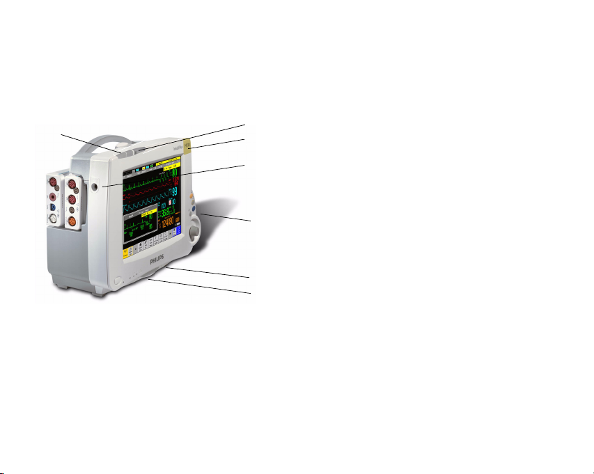
Major Parts and Keys
1
1
1 Color-coded alarm lamps
2 Alarms off lamp
3 Model indicator
4 ECG out
2
12
5 Navigation Point
6 Part number and serial number
7 Mounting quick-release lever
3
3
4
4
5
5
6
6
7
7
MP20/MP20
panel
Junior
/MP30 front
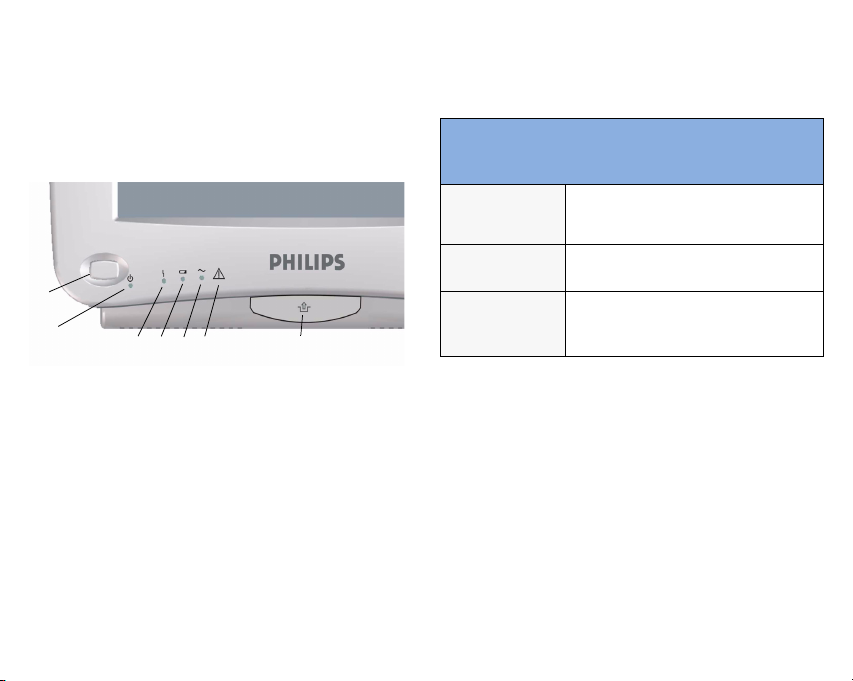
MP20/MP20Junior/MP30 LED Colors
and their Meanings
1
2
3456 7
1 On/Standby switch
2 On/Standby LED
3 Error LED
4 Battery status LED
5 AC power operation LED
6 “read the documentation” symbol
7 Mounting quick-release lever
On/Standby
LED
Error LED
Battery LED
Green when monitor is switched on
Red if there is a problem with the
monitor
Green, yellow, and red.
See the section on Using the Batteries
for details
3
Related Products
Related products extend the measurement capabilities
of your monitor. None of the related devices have their
own power on/standby switches. They take their power
from the monitor, and switch on automatically when
you turn on the monitor. A green power-on LED
indicates when they are drawing power from the
monitor. A permanently illuminated, or flashing, red
LED indicates a problem with the unit that requires
the attention of qualified service personnel.
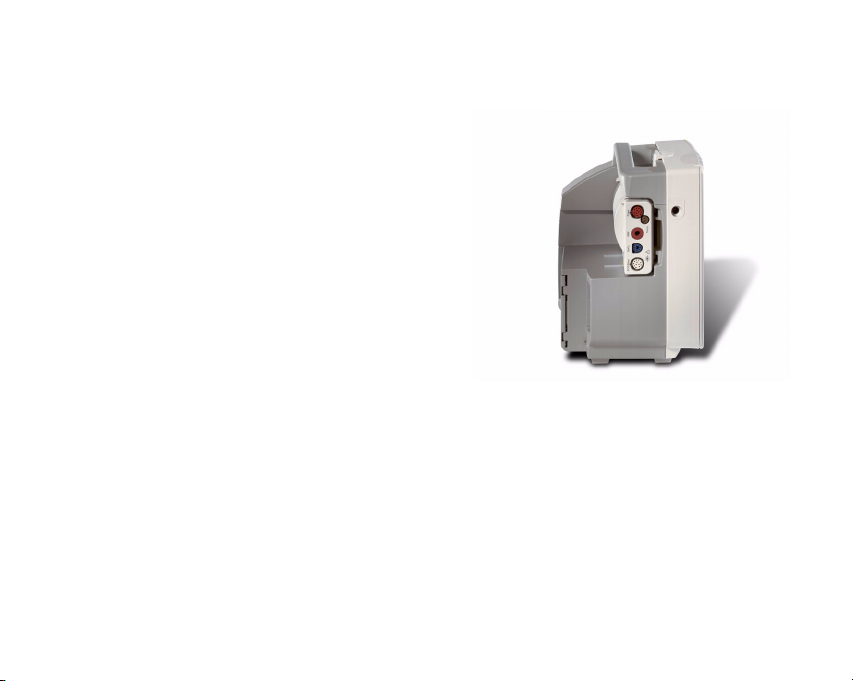
Multi-Measurement Server
(M3001A)
The Multi-Measurement Server (MMS) can
simultaneously monitor 3-, 5- or 10-lead ECG
(including arrhythmia and ST monitoring),
respiration, SpO
temperature. You can connect it to the monitor via a
cable or mount it on the back of the monitor, as shown
here.
4
, NBP and either invasive pressure or
2

Measurement Server
Extensions
The optional measurement server extensions connect
to the MMS and use the MMS settings and power.
Trend data and measurement settings from the
measurements in the extensions are stored in the
measurement server.
The measurement server extensions are not intended to
be disconnected from the MMS. To exchange an
extension, you must exchange the measurement server
and extension together.
The measurement server extensions must not be
disconnected from the host measurement server during
monitoring. When the extension is disconnected, all
measurement server and extensions settings revert to
default and any trend data stored in the measurement
server is lost.
Note: MP20/MP30 require an additional option (C30)
to be used with the extensions’ optional Cardiac
Output and Continuous Cardiac Output. MP20Junior
cannot be used with these measurements.
M3014A, M3015A and M3016A CO2
Extensions
The M3014A Capnography Extension adds
mainstream capnography, and optionally one pressure
plus either a pressure or a temperature, Cardiac Output
and Continuous Cardiac Output to the MMS. The
M3015A Microstream CO2 Extension adds
microstream capnography and optionally either
pressure or temperature to the MMS. The M3016A
Mainstream CO
capnography and either pressure or temperature to the
MMS.
Extension adds mainstream
2
M3012A Hemodynamic
Measurement Server Extension
The optional M3012A Hemodynamic Measurement
Server Extension (HMSE) can be connected to the
M3001A Multi-Measurement Server to provide the
following additional measurements: Temperature,
Pressure, an additional Pressure or Temperature, and
optionally C.O. and CCO measurements.
5
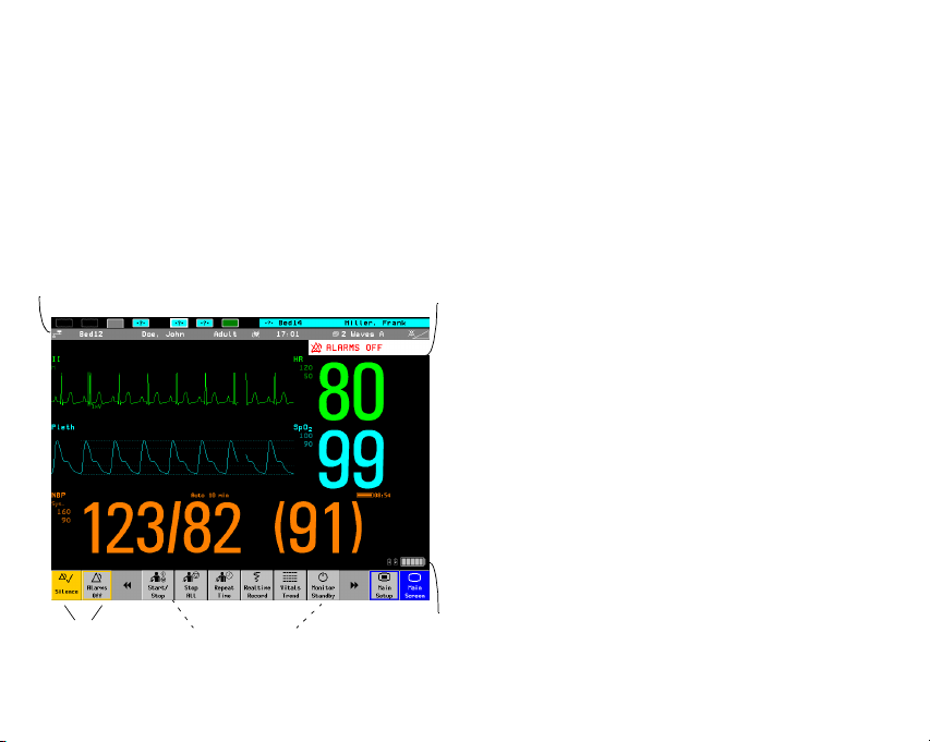
Operating and Navigating
Everything you need to operate the monitor is
contained on its screen. Almost every element on the
screen is interactive. Screen elements include
measurement numerics, waveforms, screen keys,
information fields, alarms fields and menus.
Alarms status areaInfo Line
The configurability of the monitor means that often
you can access the same element in different ways. For
example, you might be able to access an item through
its on-screen setup menu, via a hard key, or via a
SmartKey.
Select a screen element to tell the monitor to carry out
the actions linked to the element. For example, select
the HR numeric to call up the Setup ECG menu or
select the ECG wave segment to call up the ECG lead
menu.
To select an element in the monitor info line, select the
line then select the appropriate element from the
menu. For example, select the info line then the
Admit/Dischrg element from the menu to call up
the Patient Demographics window.
Using the Touchscreen
Select screen elements by pressing them directly on the
monitor’s screen.
SmartKeysAlarm Keys
6
Battery Status

Using the Navigation Point
1
2
3
4
5
1 Silence - acknowledges all active alarms by
switching off audible alarm indicators and lamps.
Exact behavior depends on permanent key
configuration
2 Alarms Off/Pause Alarms - pauses alarm indicators.
Exact behavior depends on Pause Alarms permanent
key configuration
3 Main Screen - closes all open menus and windows
and return to the main screen.
4 Back - takes you back one step to the previous
menu.
5 Navigation Point knob
To use the navigation point, rotate it left or right. With
each click, the highlight jumps to the neighboring
screen element. The element under the cursor is
highlighted. When you reach the screen element you
want, press the knob to select the element.
The elements at the top of the Screen are grouped
together for ease of navigation. Select any item at the
top of the Screen to open the Setup menu; scroll down
the menu to highlight the element you want then press
the navigation point to select the element.
7

Using Keys
The monitor has four different types of keys.
Permanent Keys
A permanent key is a graphical key that remains on the
screen all the time to give you fast access to functions.
8
Pause Alarms - pauses alarm
indicators. Pause duration depends on
monitor configuration. If pause duration is
infinite, this key is labeled
.
Off
Select again to immediately re-enable alarm
indicators.
Alarms
Silence - acknowledges all active
alarms by switching off audible alarm
indicators and lamps.
Main Screen - close all open menus and
windows and return to the main screen.
Main Setup - enter main setup menu.

SmartKeys
SmartKeys are configurable graphical keys, located at
the bottom of the main screen. They give you fast
access to functions. The selection of SmartKeys
available on your monitor depends on your monitor
configuration and on the options purchased.
Hardkeys
A hardkey is a physical key on a monitoring device,
such as the zero pressure key on the MMS.
Pop-Up Keys
Pop-up keys are task-related graphical keys that appear
automatically on the monitor screen when required.
For example, the confirm pop-up key appears only
when you need to confirm a change.
Operating Modes
When you switch the monitor on, it starts up in
monitoring mode. To change to a different mode:
1 Select the Main Setup menu.
2 Select Monitor.
3 Select Operating Modes and choose the
mode you require.
Your monitor has four operating modes. Some are
passcode protected. Passcodes can be found in the
Service Guide
• Monitoring Mode: This is the normal, every day
working mode that you use for monitoring
patients. You can change elements such as alarm
limits, patient category and so forth. When you
discharge the patient, these elements return to
their default values. Changes can be stored
permanently only in Configuration Mode. You
9

may see items, such as some menu options or the
altitude setting, that are visible but ‘grayed out’ so
that you can neither select nor change them.
These are for your information and can be
changed only in Configuration Mode.
• Demonstration Mode: Passcode protected, this is
for demonstration purposes only. You must not
change into Demonstration Mode during
monitoring. In Demonstration Mode, all stored
trend information is deleted from the monitor’s
memory.
• Configuration Mode: Passcode protected, this
mode is for personnel trained in configuration
tasks. These tasks are described in the
Configuration Guide. During installation the
monitor is configured for use in your
environment. This configuration defines the
default settings you work with when you switch
on, the number of waves you see and so forth.
• Service Mode: Passcode protected, this is for
trained service personnel.
10
When the monitor is in Demonstration Mode,
Configuration Mode, or Service Mode, this is indicated
by a box with the mode name in the center of the
Screen and in the bottom right-hand corner. Select this
field to change to a different mode.

Changing Measurement
Settings
Switching a Measurement
On and Off
Each measurement has a setup menu in which you can
adjust all of its settings. You can enter a setup menu:
• via the measurement numeric - select the
measurement numeric to enter its setup menu.
For example, to enter the Setup ECG menu,
select the HR (heartrate) numeric.
•via the Main Setup SmartKey - if you want to
setup a measurement when the measurement is
switched off, use the Main Setup SmartKey
and select Measurements. Then select the
Measurement name from the popup list. With this
SmartKey you can access any setup menu in the
monitor.
When a measurement is off, its waves and numerics are
removed from the monitor’s screen. The monitor stops
data acquisition and alarming for this measurement. A
measurement automatically switches off if you
disconnect its measurement server. If you disconnect a
transducer, the monitor replaces the measurement
numeric with question marks.
1 Enter the measurement’s setup menu and select the
measurement.
2 Select the measurement name to toggle between on
and off. The screen display indicates the active
setting.
11

Adjusting a Measurement
Wave
• To quickly adjust wave-related measurement
settings (such as speed or size), select the
measurement wave itself. This displays the
measurement
wave-related measurement settings.
12
Wave menu, which has only
Changing a Wave Speed
Lowering the wave speed compresses the wave and lets
you view a longer time period. Increasing the speed
expands the waveform, giving you a more detailed
view.
The monitor distinguishes two groups of wave speed
settings,
• RespiratorySpeed, for all respiratory waves:
, Resp. anesthetic agents and O
CO
2
• Global Speed, for all other waves.
Changing the wave group speed
1 Select Main Setup -> User Interface
2 Select Global Speed or RespiratorySpeed as required
3 Select a value from the list of available speeds.
2

Changing wave speed for a channel
1 Enter the Wave menu for a measurement by
selecting its wave.
2 Select Change Speed.
3 To set the speed to the wave group speed, select
RespiratorySpeed or Global Speed.
To set an individual channel speed, select a numeric
value from the list of available speeds to override the
wave group speed setting and set the speed for the
individual wave channel on the monitor Screen.
The wave channel speed is independent of the wave
(label) depicted in the channel, if you change the
wave, the new wave will retain the set channel
speed.
Changing Monitor Settings
• To change monitor settings such as date and time,
brightness, or QRS tone volume, select the
Main Setup SmartKey and then select the
setting you want to change, or select User
Interface to enter a submenu where you can
change user interface settings.
13

1Starting Monitoring
Inspecting the Monitor
1 Before you start to make measurements, carry out
the following checks on the monitor including all
connected Measurement Servers, or measurement
server extensions.
– Check for any mechanical damage.
– Check all the external cables, plug-ins and
accessories.
2 Plug the power cord into the AC power source. If
you are using battery power, ensure that the battery
has sufficient power for monitoring. When you use
a battery for the first time, you must charge it,
following the instructions given in the Instructions
for Use section on Charging Batteries.
3 Check all the functions of the instrument that you
need to monitor the patient, and ensure that the
instrument is in good working order.
14
Switching On
• Press the on/off switch on the monitor for one
second. The monitor performs a self test and is
then ready to use. If you see a message such as
CO2 Sensor Warmup wait until it
disappears before starting monitoring that
measurement. Connected devices usually take
their power from the monitor

Setting up the Measurement
Servers
1 Decide which measurements you want to make.
2 Connect the required Measurement Servers, or
Measurement Server Extensions.
3 Check that you have the correct patient cables and
transducers plugged in. The connectors are colorcoded to the patient cables and transducers for easy
identification.
Starting Monitoring
After you switch on the monitor,
1 Admit your patient to the monitor.
2 Check that the profile, alarm limits, alarm and QRS
volumes, patient category and paced status and so
forth are appropriate for your patient. Change them
if necessary.
3 Refer to the appropriate measurement section of the
Instructions for Use for details of how to perform
the measurements you require.
15

Disconnecting from Power
Networked Monitoring
The On/Standby switch does not disconnect the
monitor from the ac power source. To disconnect,
unplug the power cable.
16
If your monitor is connected to a network, a network
symbol is displayed in the upper left corner next to the
bed label.
Select the monitor info line and Bed
Information from the menu to see details of the
Care Group, the equipment label and technical
information about the network.
Note: MP20Junior has no network capability.

Using the Batteries
One OR two Philips M4605A rechargeable Lithium
Ion batteries must be inserted into the battery
compartment at the rear of the monitor to use the
MP20/MP20Junior/MP30 monitor with battery
power.
Battery compartment
You can switch between battery-powered and mainspowered (AC) operation without interrupting
monitoring.
The batteries recharge automatically whenever the
monitor is connected to mains power.
Battery Indicators and Status
Information
The battery LED and battery status information on the
Main Screen, in combination with INOP messages and
prompts, help you keep track of the battery power
status. The indicators always show the remaining
capacity in relation to the battery’s actual maximum
capacity, which may lessen as the battery ages. An
estimate of the monitoring time available with the
current battery capacity is also shown. You can see the
actual capacity in the Battery Status window.
17

Battery LED
Battery LED Colors When monitor on mains
power, this means
Green
Ye ll ow
battery power is > 90%
batteries charging (battery power
<90%)
Red, flashing
Red, flashes intermittently
battery malfunction battery malfunction
Red, flashes once when
on/standby switch is
pressed
18
When monitor on battery power,
this means
less than 10 minutes power remaining
not enough battery power left to power
monitor
 Loading...