

Page 1

IntelliVue Information Center System
Installation and Service Manual
Part Number M3150-94230
Printed in the U.S.A. August 2003
Edition 1
Page 2

Notice
Proprietary Information
This document contains proprietary information, which is protected by copyright. All Rights
Reserved. Reproduction, adaptation, or translation without prior written permission is
prohibited, except as allowed under the copyright laws.
Philips Medical Systems
3000 Minuteman Road
Andover, MA 01810-1085
(978) 687-1501
Printed in USA
Warranty The information contained in this document is subject to change without notice.
Philips Medical Systems makes no warranty of any kind with regard to this material,
including, but not limited to, the implied warranties or merchantability and fitness for Philips
Medical Systems shall not be liable for errors contained herein or for incidental or
consequential damages in connection with the furnishing, performance, or use of this material.
Copyright Copyright © 2003 Philips Electronics North America Corporation
Acknowledg ements
Windows and MS SQL Server are registered Trademarks of Microsoft Corporation,
Copyright 2003.
Printing History
Software Release History
New editions of this document incorporate all material updated since the previous edition.
Update packages may be issued between editions and contain replacement and additional
pages to be merged by a revision date at the bottom of the page. Pages that are rearranged due
to changes on a previous page are not considered revised.
The documentation printing date and part number indicate its current edition. The printing
date changes when a new edition is printed. (Minor corrections and updates that are
incorporated at reprint do not cause the date to change.) The document part number changes
when extensive technical changes are incorporated.
First Edition ............................................................... August 2003
M3150B IntelliVue Information Center Local Database
M3155B IntelliVue Information Center Network Database
M3151B IntelliVue Information Center Client
M3170 Patient Link
M3169A IntelliVue Small Database Server
M3154B IntelliVue Database Server
Release E.01.xx
2
Page 3

Software Release History
Release
VUF
E.01.xx 453563488021
E.00.27 M3290-11013
E.00.25 M3290-11012 Kayak D5765T
Part Number
453563488031
453563494791
SSN
Prefix
Date Hardware Description
08/03 Vectra VL400 P3715W
Vectra VL400 P5068W
Vectra VL420 A8183S
M3167A- Evo D510
NetServer P2478U
NetServer P2478W
M3168B- ML370
ML370 G3
8/03 Kayak D5765T
Kayak D6723T
Kayak D6731T VL400
P3715W VL400
P5068W VL420 A8183S
Evo D510
Kayak D6723T
Kayak D6731T
Vectra VL400 P3715W
Vectra VL400 P5068W
Vectra VL420 A8183S
M3167A- Evo D510
M31 - Evo D
NetServer D5000A
NetServer P2478U
NetServer P2478W
M3168B- ML370
M - ML
Release of Information Center
software Version E.01.xx
Release of Information Center
software Version E.00.27
Release of Information Center
software Version E.00.25
E.00.23 M3290-11010 01/03 Kayak D5765T
Kayak D6723T
Kayak D6731T
Vectra VL400 P3715W
Vectra VL400 P5068W
Vectra VL420 A8183S
M3167A- Evo D510
NetServer D5000A
NetServer P2478U
NetServer P2478W
M3168B- ML370
Release of Information Center
software Version E.00.xx
3
Page 4

About this Document
This document contains Service and Installation information for the M3154 IntelliVue
Database Server, M3169 IntelliVue Small Database Server, M3150 IntelliVue Information
Center Local Database, M3155 IntelliVue Information Center Network Database, M3170
Patient Link, and the M3151 IntelliVue Information Center Client, (hereinafter called the
Database Server, Information Center, or Information Center Client or called by their
respective model number). Refer to the product’s Application Software Release History with
the Supported PC Hardware list.
4
Page 5
Text
The following conventions for Notes, Cautions, and Warnings are used in this manual.
Convention
s
Note A Note calls attention to an important point in the text.
Caution A Caution calls attention to a condition or possible situation that could damage or
destroy the product or the user’s work.
Warning A Warning calls attention to a condition or possible situation that could cause injury to
the user and/or patient.
Explanation of Symbols
Symbols on products and packaging mean the following:
Defibrillator-proof type CF equipment
Caution: Consult accompanying documents.
Signal (ECG) Input
Signal (ECG) Output
Data input/output
Alternating Current
Direct Current
Protective earth
5
Page 6
Equipotential grounding post
Temperature
Humidity
Altitude or atmospheric pressure
Contains parts to be recycled
Contains parts that may not be put into normal waste disposal but must be recycled
or dealt with as chemical waste
Fragile, handle with care
Keep dry
Consult instructions for use
Date of manufacture
Serial number
Catalog number
Batch code
6
Page 7

IntelliVue Information Center Service Kit
The Information Center Service Kit contains documentation that supports the IntelliVue
Information Center system. The Service Kit has two principal parts -- Quick Reference
Guides and a Documentation CDROM.
Printed
Documentation
Documentation
CD-ROM
Quick Reference Service Guides provide a handy, quick reference of key information.
Service and User Documentation CD ROM contains:
• Database Server Quick Reference Guide
• Information Center Quick Reference Guide
• Clinical Network Quick Reference Guide
• Information Center System Installation and Service Manual
• HL7 Programmer’s Guide
• Information Center Instructions for Use
• Information Center Installation Notes
• Application Notes
• 3rd party service documentation (e.g. PC Workstation, Server, Printer, etc)
Philips Software License Terms
ATTENTION: USE OF THE SOFTWARE IS SUBJECT TO THE PHILIPS SOFTWARE LICENSE
TERMS SET FORTH BELOW. USING THE SOFTWARE INDICATES YOUR
ACCEPTANCE OF THESE LICENSE TERMS. IF YOU DO NOT ACCEPT THESE
LICENSE TERMS, YOU MAY RETURN THE SOFTWARE FOR A FULL REFUND. IF
THE SOFTWARE IS BUNDLED WITH ANOTHER PRODUCT, YOU MAY RETURN
THE ENTIRE UNUSED PRODUCT FOR A FULL REFUND.
PHILIPS SOFTWARE LICENSE TERMS
The following License Terms govern your use of the accompanying Software unless you have
a separate signed agreement with Philips Medical Systems.
License Grant. Philips Medical Systems grants you a license to Use one copy of the
Software. “Use” means storing, loading, installing, executing or displaying the Software. You
may not modify the Software or disable any licensing or control features of the Software. If
the Software is licensed for “concurrent use”, you may not allow more than the maximum
number of authorized users to Use the Software concurrently.
Ownership. The Software is owned and copyrighted by Philips or its third party suppliers.
Your license confers no title to, or ownership in, the Software and is not a sale of any rights in
the Software. Philips’ third party suppliers may protect their rights in the event of any
violation of these License Terms.
Copies and Adaptations. You may only make copies or adaptations of the Software for
archival purposes or when copying or adaptation is an essential step in the authorized Use of
the Software. You must reproduce all copyright notices in the original Software on all copies
or adaptations. You may not copy the Software onto any public network.
7
Page 8

No Disassembly or Decryption. You may not disassemble or decompile the Software unless
Philips prior written consent is obtained. In some jurisdictions, Philips consent may not be
required for limited disassembly or decompilation. Upon request, you will provide Philips
with reasonably detailed information regarding any disassembly or decompilation. You may
not decrypt the Software unless decryption is a necessary part of the operation of the
Software.
Transfer. Your license will automatically terminate upon any transfer of the Software. Upon
transfer, you must deliver the Software, including any copies and related documentation, to
the transferee. The transferee must accept these License Terms as a condition to the transfer.
Termination. Philips Medical Systems may terminate your license upon notice for failure to
comply with any of these License Terms. Upon termination, you must immediately destroy
the Software, together with all copies, adaptations and merged portions in any form.
Export Requirements. You may not export or re-export the Software or any copy or
adaptation in violation of any applicable laws or regulations.
U.S. Government Restricted Rights. The Software and any accompanying documentation
have been developed entirely at private expense. They are delivered and licensed as
“commercial computer software” as defined in DFARS 252.227-7013 (Oct. 1988), DFARS
252.211-7015 (May 1991) or DFARS 252.227-7014 (Jun. 1995), as a “commercial item” as
defined in FAR 2.101(a), or as “Restricted computer software” as defined in FAR 52.227-19
(Jun. 1987)(or any equivalent agency regulation or contract clause), whichever is applicable.
You have only those rights provided for such Software and any accompanying documentation
by the applicable FAR or DFARS clause or the Philips standard software agreement for the
product involved.
8
Page 9

Table of Contents
Notice. . . . . . . . . . . . . . . . . . . . . . . . . . . . . . . . . . . . . . . . . . . . . . . . . . . . . . . . . . . . . . .1-2
Proprietary Information. . . . . . . . . . . . . . . . . . . . . . . . . . . . . . . . . . . . . . . . . . . . . . .1-2
Warranty. . . . . . . . . . . . . . . . . . . . . . . . . . . . . . . . . . . . . . . . . . . . . . . . . . . . . . . . . .1-2
Copyright . . . . . . . . . . . . . . . . . . . . . . . . . . . . . . . . . . . . . . . . . . . . . . . . . . . . . . . . .1-2
Acknowledgements . . . . . . . . . . . . . . . . . . . . . . . . . . . . . . . . . . . . . . . . . . . . . . . . .1-2
Printing History . . . . . . . . . . . . . . . . . . . . . . . . . . . . . . . . . . . . . . . . . . . . . . . . . . . . .1-2
Software Release History. . . . . . . . . . . . . . . . . . . . . . . . . . . . . . . . . . . . . . . . . . . . .1-2
About this Document . . . . . . . . . . . . . . . . . . . . . . . . . . . . . . . . . . . . . . . . . . . . . . . . . .1-4
Text Conventions . . . . . . . . . . . . . . . . . . . . . . . . . . . . . . . . . . . . . . . . . . . . . . . . . . .1-5
Explanation of Symbols . . . . . . . . . . . . . . . . . . . . . . . . . . . . . . . . . . . . . . . . . . . . . .1-5
IntelliVue Information Center Service Kit . . . . . . . . . . . . . . . . . . . . . . . . . . . . . . . . .1-7
Printed Documentation . . . . . . . . . . . . . . . . . . . . . . . . . . . . . . . . . . . . . . . . . . 1-7
Documentation CD-ROM . . . . . . . . . . . . . . . . . . . . . . . . . . . . . . . . . . . . . . . . . 1-7
Philips Software License Terms . . . . . . . . . . . . . . . . . . . . . . . . . . . . . . . . . . . . . . . .1-7
ATTENTION: . . . . . . . . . . . . . . . . . . . . . . . . . . . . . . . . . . . . . . . . . . . . . . . . . . 1-7
Introducing the IntelliVue Information Center System . . . . . . . . . . . . . .1-1
Overview . . . . . . . . . . . . . . . . . . . . . . . . . . . . . . . . . . . . . . . . . . . . . . . . . . . . . . . . . . . .1-1
Information Center System . . . . . . . . . . . . . . . . . . . . . . . . . . . . . . . . . . . . . . . . . . . . .1-2
M3150 Information Center Local Database . . . . . . . . . . . . . . . . . . . . . . . . . . . . . . .1-2
Independent Operation . . . . . . . . . . . . . . . . . . . . . . . . . . . . . . . . . . . . . . . . . . 1-2
Standard Components . . . . . . . . . . . . . . . . . . . . . . . . . . . . . . . . . . . . . . . . . . . 1-2
Optional Components . . . . . . . . . . . . . . . . . . . . . . . . . . . . . . . . . . . . . . . . . . . 1-3
M3155 Information Center Network Database . . . . . . . . . . . . . . . . . . . . . . . . . . . . .1-4
Standard Components . . . . . . . . . . . . . . . . . . . . . . . . . . . . . . . . . . . . . . . . . . . 1-4
Optional Components . . . . . . . . . . . . . . . . . . . . . . . . . . . . . . . . . . . . . . . . . . . 1-4
M3151 Information Center Client . . . . . . . . . . . . . . . . . . . . . . . . . . . . . . . . . . . . . . .1-5
Standard Components . . . . . . . . . . . . . . . . . . . . . . . . . . . . . . . . . . . . . . . . . . . 1-5
Optional Components . . . . . . . . . . . . . . . . . . . . . . . . . . . . . . . . . . . . . . . . . . . 1-5
M3170 Patient Link. . . . . . . . . . . . . . . . . . . . . . . . . . . . . . . . . . . . . . . . . . . . . . . . . .1-6
Standard Components . . . . . . . . . . . . . . . . . . . . . . . . . . . . . . . . . . . . . . . . . . . 1-6
M3154 Database Server . . . . . . . . . . . . . . . . . . . . . . . . . . . . . . . . . . . . . . . . . . . . .1-7
Large Network Database System. . . . . . . . . . . . . . . . . . . . . . . . . . . . . . . . . . . . . . .1-8
M3169 Small Database Server . . . . . . . . . . . . . . . . . . . . . . . . . . . . . . . . . . . . . . . .1-8
Topologies. . . . . . . . . . . . . . . . . . . . . . . . . . . . . . . . . . . . . . . . . . . . . . . . . . . . . . . . . .1-10
Philips CareNet . . . . . . . . . . . . . . . . . . . . . . . . . . . . . . . . . . . . . . . . . . . . . . . . . . . . . .1-13
Network Cabling . . . . . . . . . . . . . . . . . . . . . . . . . . . . . . . . . . . . . . . . . . . . . . . . . . .1-13
Patient Monitors . . . . . . . . . . . . . . . . . . . . . . . . . . . . . . . . . . . . . . . . . . . . . . . . . . . . .1-14
Features. . . . . . . . . . . . . . . . . . . . . . . . . . . . . . . . . . . . . . . . . . . . . . . . . . . . . . . . . . . .1-17
Main Screen . . . . . . . . . . . . . . . . . . . . . . . . . . . . . . . . . . . . . . . . . . . . . . . . . . . . . .1-17
Contents 1
Page 10

Table of Contents
Patient Window . . . . . . . . . . . . . . . . . . . . . . . . . . . . . . . . . . . . . . . . . . . . . . . . . . .1-18
All Controls Window . . . . . . . . . . . . . . . . . . . . . . . . . . . . . . . . . . . . . . . . . . . . . . . .1-19
Patient Management . . . . . . . . . . . . . . . . . . . . . . . . . . . . . . . . . . . . . . . . . . . 1-19
Alarm Management and Setup . . . . . . . . . . . . . . . . . . . . . . . . . . . . . . . . . . . 1-19
Patient Data Review . . . . . . . . . . . . . . . . . . . . . . . . . . . . . . . . . . . . . . . . . . . 1-19
Configuration and Support. . . . . . . . . . . . . . . . . . . . . . . . . . . . . . . . . . . . . . . 1-19
Patient Data Storage . . . . . . . . . . . . . . . . . . . . . . . . . . . . . . . . . . . . . . . . . . . . . . .1-20
Patient Data Review . . . . . . . . . . . . . . . . . . . . . . . . . . . . . . . . . . . . . . . . . . . 1-20
Alert Data Export . . . . . . . . . . . . . . . . . . . . . . . . . . . . . . . . . . . . . . . . . . . . . . 1-21
Data Reliability. . . . . . . . . . . . . . . . . . . . . . . . . . . . . . . . . . . . . . . . . . . . . . . . 1-22
Remote Access . . . . . . . . . . . . . . . . . . . . . . . . . . . . . . . . . . . . . . . . . . . . . . . 1-22
Information Center Web Access . . . . . . . . . . . . . . . . . . . . . . . . . . . . . . . . . . 1-22
Service. . . . . . . . . . . . . . . . . . . . . . . . . . . . . . . . . . . . . . . . . . . . . . . . . . . . . . 1-24
Configuration . . . . . . . . . . . . . . . . . . . . . . . . . . . . . . . . . . . . . . . . . . . . . . . . . . . . .1-25
System Configuration . . . . . . . . . . . . . . . . . . . . . . . . . . . . . . . . . . . . . . . . . . 1-25
Patient Monitoring Configuration . . . . . . . . . . . . . . . . . . . . . . . . . . . . . . . . . . 1-26
Configuration Archiving and Restoration . . . . . . . . . . . . . . . . . . . . . . . . . . . . 1-26
On-Line Help . . . . . . . . . . . . . . . . . . . . . . . . . . . . . . . . . . . . . . . . . . . . . . . . . . . . .1-26
Clinical Applications . . . . . . . . . . . . . . . . . . . . . . . . . . . . . . . . . . . . . . . . . . . . . . . . .1-29
Patient Monitoring . . . . . . . . . . . . . . . . . . . . . . . . . . . . . . . . . . . . . . . . . . . . . . . . .1-29
Typical Plug-in Modules . . . . . . . . . . . . . . . . . . . . . . . . . . . . . . . . . . . . . . . . 1-29
Waves and Parameters . . . . . . . . . . . . . . . . . . . . . . . . . . . . . . . . . . . . . . . . . 1-30
Telemetry Monitoring . . . . . . . . . . . . . . . . . . . . . . . . . . . . . . . . . . . . . . . . . . . 1-31
Alarm Annunciation . . . . . . . . . . . . . . . . . . . . . . . . . . . . . . . . . . . . . . . . . . . . . . . .1-32
Priorities. . . . . . . . . . . . . . . . . . . . . . . . . . . . . . . . . . . . . . . . . . . . . . . . . . . . . 1-32
Annunciation . . . . . . . . . . . . . . . . . . . . . . . . . . . . . . . . . . . . . . . . . . . . . . . . . 1-32
Arrhythmia Monitoring . . . . . . . . . . . . . . . . . . . . . . . . . . . . . . . . . . . . . . . . . . . . . .1-33
Basic Arrhythmia . . . . . . . . . . . . . . . . . . . . . . . . . . . . . . . . . . . . . . . . . . . . . . 1-34
Enhanced Arrhythmia . . . . . . . . . . . . . . . . . . . . . . . . . . . . . . . . . . . . . . . . . . 1-34
ST Segment Monitoring . . . . . . . . . . . . . . . . . . . . . . . . . . . . . . . . . . . . . . . . . . . . .1-35
EASI 12-Lead ECG Review and Report. . . . . . . . . . . . . . . . . . . . . . . . . . . . . . . . .1-35
Patient Data Review. . . . . . . . . . . . . . . . . . . . . . . . . . . . . . . . . . . . . . . . . . . . . . . .1-35
Alarm Review. . . . . . . . . . . . . . . . . . . . . . . . . . . . . . . . . . . . . . . . . . . . . . . . . 1-35
Trend Review. . . . . . . . . . . . . . . . . . . . . . . . . . . . . . . . . . . . . . . . . . . . . . . . . 1-36
Event Review. . . . . . . . . . . . . . . . . . . . . . . . . . . . . . . . . . . . . . . . . . . . . . . . . 1-37
Upgrades . . . . . . . . . . . . . . . . . . . . . . . . . . . . . . . . . . . . . . . . . . . . . . . . . . . . . . . . . . .1-38
Memory Requirements. . . . . . . . . . . . . . . . . . . . . . . . . . . . . . . . . . . . . . . . . . 1-38
Hard Disk Requirements . . . . . . . . . . . . . . . . . . . . . . . . . . . . . . . . . . . . . . . . 1-38
BIOS Requirements . . . . . . . . . . . . . . . . . . . . . . . . . . . . . . . . . . . . . . . . . . . . 1-40
Components and Options . . . . . . . . . . . . . . . . . . . . . . . . . . . . . . . . . . . . . . . . . . . . .1-42
Basic Systems . . . . . . . . . . . . . . . . . . . . . . . . . . . . . . . . . . . . . . . . . . . . . . . . . . . .1-42
Purchased Options. . . . . . . . . . . . . . . . . . . . . . . . . . . . . . . . . . . . . . . . . . . . . . . . .1-43
2 Channel Recorder Options . . . . . . . . . . . . . . . . . . . . . . . . . . . . . . . . . . . . . . . . .1-44
4 Channel Recorder Options . . . . . . . . . . . . . . . . . . . . . . . . . . . . . . . . . . . . . . . . .1-44
Contents 2
Page 11

Table of Contents
Display Options . . . . . . . . . . . . . . . . . . . . . . . . . . . . . . . . . . . . . . . . . . . . . . . . . . .1-44
Upgrade Options . . . . . . . . . . . . . . . . . . . . . . . . . . . . . . . . . . . . . . . . . . . . . . . . . .1-45
Printer Options . . . . . . . . . . . . . . . . . . . . . . . . . . . . . . . . . . . . . . . . . . . . . . . . . . . .1-47
Mounting Options . . . . . . . . . . . . . . . . . . . . . . . . . . . . . . . . . . . . . . . . . . . . . . . . . .1-47
Clinical Network Active Components . . . . . . . . . . . . . . . . . . . . . . . . . . . . . . . . . . .1-48
Cabling Installation Materials . . . . . . . . . . . . . . . . . . . . . . . . . . . . . . . . . . . . . . . . .1-48
Cable Options. . . . . . . . . . . . . . . . . . . . . . . . . . . . . . . . . . . . . . . . . . . . . . . . . . . . .1-49
SDN Installation Materials . . . . . . . . . . . . . . . . . . . . . . . . . . . . . . . . . . . . . . . . . . .1-50
Language Options . . . . . . . . . . . . . . . . . . . . . . . . . . . . . . . . . . . . . . . . . . . . . . . . .1-50
Hardware Description . . . . . . . . . . . . . . . . . . . . . . . . . . . . . . . . . . . . . . . .2-1
Overview . . . . . . . . . . . . . . . . . . . . . . . . . . . . . . . . . . . . . . . . . . . . . . . . . . . . . . . . . . . .2-1
System Components . . . . . . . . . . . . . . . . . . . . . . . . . . . . . . . . . . . . . . . . . . . . . . . . . .2-2
PC Workstations. . . . . . . . . . . . . . . . . . . . . . . . . . . . . . . . . . . . . . . . . . . . . . . . . . . .2-2
M3154 Database Server . . . . . . . . . . . . . . . . . . . . . . . . . . . . . . . . . . . . . . . . . . . . .2-3
Mouse/Trackball. . . . . . . . . . . . . . . . . . . . . . . . . . . . . . . . . . . . . . . . . . . . . . . . 2-3
Keyboard . . . . . . . . . . . . . . . . . . . . . . . . . . . . . . . . . . . . . . . . . . . . . . . . . . . . . 2-3
Display . . . . . . . . . . . . . . . . . . . . . . . . . . . . . . . . . . . . . . . . . . . . . . . . . . . . . . . 2-4
Computer Memory . . . . . . . . . . . . . . . . . . . . . . . . . . . . . . . . . . . . . . . . . . . . . . 2-4
Hard Drive . . . . . . . . . . . . . . . . . . . . . . . . . . . . . . . . . . . . . . . . . . . . . . . . . . . . 2-4
Monitoring LAN . . . . . . . . . . . . . . . . . . . . . . . . . . . . . . . . . . . . . . . . . . . . . . . . 2-4
Hospital LAN Card . . . . . . . . . . . . . . . . . . . . . . . . . . . . . . . . . . . . . . . . . . . . . . 2-4
SDN/Recorder Interface Card . . . . . . . . . . . . . . . . . . . . . . . . . . . . . . . . . . . . . 2-4
Audio Card and Speaker . . . . . . . . . . . . . . . . . . . . . . . . . . . . . . . . . . . . . . . . . 2-4
CD ROM Drive . . . . . . . . . . . . . . . . . . . . . . . . . . . . . . . . . . . . . . . . . . . . . . . . . 2-4
Floppy Disk Drive. . . . . . . . . . . . . . . . . . . . . . . . . . . . . . . . . . . . . . . . . . . . . . . 2-4
Video Card. . . . . . . . . . . . . . . . . . . . . . . . . . . . . . . . . . . . . . . . . . . . . . . . . . . . 2-4
Modem. . . . . . . . . . . . . . . . . . . . . . . . . . . . . . . . . . . . . . . . . . . . . . . . . . . . . . . 2-5
RAID 5 . . . . . . . . . . . . . . . . . . . . . . . . . . . . . . . . . . . . . . . . . . . . . . . . . . . . . . . 2-5
Panel Descriptions . . . . . . . . . . . . . . . . . . . . . . . . . . . . . . . . . . . . . . . . . . . . . . 2-6
Displays . . . . . . . . . . . . . . . . . . . . . . . . . . . . . . . . . . . . . . . . . . . . . . . . . . . . . . . . . .2-9
CRT Displays . . . . . . . . . . . . . . . . . . . . . . . . . . . . . . . . . . . . . . . . . . . . . . . . . . 2-9
Flat Panel Display . . . . . . . . . . . . . . . . . . . . . . . . . . . . . . . . . . . . . . . . . . . . . 2-10
Touch Flat Panel Display . . . . . . . . . . . . . . . . . . . . . . . . . . . . . . . . . . . . . . . . 2-10
Dual Display Option . . . . . . . . . . . . . . . . . . . . . . . . . . . . . . . . . . . . . . . . . . . . 2-11
Remote Slave Displays . . . . . . . . . . . . . . . . . . . . . . . . . . . . . . . . . . . . . . . . . 2-11
Video Splitters . . . . . . . . . . . . . . . . . . . . . . . . . . . . . . . . . . . . . . . . . . . . . . . . 2-11
Keyboard-Video-Mouse Switch . . . . . . . . . . . . . . . . . . . . . . . . . . . . . . . . . . . . . . .2-12
Philips Recorder Systems . . . . . . . . . . . . . . . . . . . . . . . . . . . . . . . . . . . . . . . . . . .2-13
Recorder Module . . . . . . . . . . . . . . . . . . . . . . . . . . . . . . . . . . . . . . . . . . . . . . 2-14
Recorder Rack . . . . . . . . . . . . . . . . . . . . . . . . . . . . . . . . . . . . . . . . . . . . . . . . 2-16
60 VDC Power Supply . . . . . . . . . . . . . . . . . . . . . . . . . . . . . . . . . . . . . . . . . . 2-17
Speaker . . . . . . . . . . . . . . . . . . . . . . . . . . . . . . . . . . . . . . . . . . . . . . . . . . . . . . . . .2-18
Philips 4-Channel Recorder (Optional) . . . . . . . . . . . . . . . . . . . . . . . . . . . . . 2-18
Contents 3
Page 12

Table of Contents
Printer. . . . . . . . . . . . . . . . . . . . . . . . . . . . . . . . . . . . . . . . . . . . . . . . . . . . . . . . . . .2-22
Printer Hub . . . . . . . . . . . . . . . . . . . . . . . . . . . . . . . . . . . . . . . . . . . . . . . . . . . . . . .2-23
Uninterruptible Power Supply. . . . . . . . . . . . . . . . . . . . . . . . . . . . . . . . . . . . . . . . .2-24
Dip Switches . . . . . . . . . . . . . . . . . . . . . . . . . . . . . . . . . . . . . . . . . . . . . . . . . 2-25
Operation . . . . . . . . . . . . . . . . . . . . . . . . . . . . . . . . . . . . . . . . . . . . . . . . . . . . 2-26
Power Distribution Module . . . . . . . . . . . . . . . . . . . . . . . . . . . . . . . . . . . . . . . . . . .2-27
Mounting . . . . . . . . . . . . . . . . . . . . . . . . . . . . . . . . . . . . . . . . . . . . . . . . . . . . . . . . . . .2-29
Display Mounts. . . . . . . . . . . . . . . . . . . . . . . . . . . . . . . . . . . . . . . . . . . . . . . . . . . .2-29
Keyboard Mounts . . . . . . . . . . . . . . . . . . . . . . . . . . . . . . . . . . . . . . . . . . . . . . . . . .2-29
Computer System Mounts . . . . . . . . . . . . . . . . . . . . . . . . . . . . . . . . . . . . . . . . . . .2-30
Processing Unit Mount. . . . . . . . . . . . . . . . . . . . . . . . . . . . . . . . . . . . . . . . . . 2-30
UPS Mount . . . . . . . . . . . . . . . . . . . . . . . . . . . . . . . . . . . . . . . . . . . . . . . . . . 2-31
CareNet . . . . . . . . . . . . . . . . . . . . . . . . . . . . . . . . . . . . . . . . . . . . . . . . . . . . . . . . . . . .2-33
Serial Distribution Network . . . . . . . . . . . . . . . . . . . . . . . . . . . . . . . . . . . . . . . . . . .2-34
System Description . . . . . . . . . . . . . . . . . . . . . . . . . . . . . . . . . . . . . . . . . . . . 2-34
Components. . . . . . . . . . . . . . . . . . . . . . . . . . . . . . . . . . . . . . . . . . . . . . . . . . 2-34
Star Topology . . . . . . . . . . . . . . . . . . . . . . . . . . . . . . . . . . . . . . . . . . . . . . . . . 2-34
System Communications Controller . . . . . . . . . . . . . . . . . . . . . . . . . . . . . . . . . . . .2-36
SDN Interface Card . . . . . . . . . . . . . . . . . . . . . . . . . . . . . . . . . . . . . . . . . . . . . . . .2-36
Branch Cables . . . . . . . . . . . . . . . . . . . . . . . . . . . . . . . . . . . . . . . . . . . . . . . . . . . .2-36
SDC . . . . . . . . . . . . . . . . . . . . . . . . . . . . . . . . . . . . . . . . . . . . . . . . . . . . . . . . 2-37
XSDC. . . . . . . . . . . . . . . . . . . . . . . . . . . . . . . . . . . . . . . . . . . . . . . . . . . . . . . 2-37
UTP . . . . . . . . . . . . . . . . . . . . . . . . . . . . . . . . . . . . . . . . . . . . . . . . . . . . . . . . 2-37
LDC . . . . . . . . . . . . . . . . . . . . . . . . . . . . . . . . . . . . . . . . . . . . . . . . . . . . . . . . 2-37
Wall Box Kits . . . . . . . . . . . . . . . . . . . . . . . . . . . . . . . . . . . . . . . . . . . . . . . . . . . . .2-38
Cables . . . . . . . . . . . . . . . . . . . . . . . . . . . . . . . . . . . . . . . . . . . . . . . . . . . . . . . . . . . . .2-39
Cable Descriptions . . . . . . . . . . . . . . . . . . . . . . . . . . . . . . . . . . . . . . . . . . . . . . . . .2-39
Cable Pin Connections. . . . . . . . . . . . . . . . . . . . . . . . . . . . . . . . . . . . . . . . . . . . . .2-42
Recorder Rack/Power Supply Cable . . . . . . . . . . . . . . . . . . . . . . . . . . . . . . . 2-43
SDN Wall Box and Signal Cable . . . . . . . . . . . . . . . . . . . . . . . . . . . . . . . . . . 2-44
Computer Cards . . . . . . . . . . . . . . . . . . . . . . . . . . . . . . . . . . . . . . . . . . . . . . . . . . . . .2-46
Dual Video Graphics Card . . . . . . . . . . . . . . . . . . . . . . . . . . . . . . . . . . . . . . . . . . .2-46
Audio Sound Card . . . . . . . . . . . . . . . . . . . . . . . . . . . . . . . . . . . . . . . . . . . . . . . . .2-47
Specifications . . . . . . . . . . . . . . . . . . . . . . . . . . . . . . . . . . . . . . . . . . . . . . . . . . . . . . .2-48
Physical . . . . . . . . . . . . . . . . . . . . . . . . . . . . . . . . . . . . . . . . . . . . . . . . . . . . . . . . .2-48
Environmental . . . . . . . . . . . . . . . . . . . . . . . . . . . . . . . . . . . . . . . . . . . . . . . . . . . .2-49
Electrical. . . . . . . . . . . . . . . . . . . . . . . . . . . . . . . . . . . . . . . . . . . . . . . . . . . . . . . . .2-50
Customer Supplied Displays . . . . . . . . . . . . . . . . . . . . . . . . . . . . . . . . . . . . . . . . .2-51
Flat Panel Specifications . . . . . . . . . . . . . . . . . . . . . . . . . . . . . . . . . . . . . . . . 2-52
External Modem . . . . . . . . . . . . . . . . . . . . . . . . . . . . . . . . . . . . . . . . . . . . . . . . . . .2-53
Regulatory . . . . . . . . . . . . . . . . . . . . . . . . . . . . . . . . . . . . . . . . . . . . . . . . . . . . . . . . . .2-56
Contents 4
Page 13

Table of Contents
Philips Software . . . . . . . . . . . . . . . . . . . . . . . . . . . . . . . . . . . . . . . . . . . . . . . . . . .2-56
Philips Hardware . . . . . . . . . . . . . . . . . . . . . . . . . . . . . . . . . . . . . . . . . . . . . . . . . .2-56
Software Description . . . . . . . . . . . . . . . . . . . . . . . . . . . . . . . . . . . . . . . . .3-1
Overview . . . . . . . . . . . . . . . . . . . . . . . . . . . . . . . . . . . . . . . . . . . . . . . . . . . . . . . . . . . .3-1
PC Workstation Platform . . . . . . . . . . . . . . . . . . . . . . . . . . . . . . . . . . . . . . . . . . . . . . .3-2
Peripheral Devices . . . . . . . . . . . . . . . . . . . . . . . . . . . . . . . . . . . . . . . . . . . . . . . . . .3-3
Windows Operating System . . . . . . . . . . . . . . . . . . . . . . . . . . . . . . . . . . . . . . . . . . . .3-4
Operating System. . . . . . . . . . . . . . . . . . . . . . . . . . . . . . . . . . . . . . . . . . . . . . . . . . .3-4
Application Programming Interfaces . . . . . . . . . . . . . . . . . . . . . . . . . . . . . . . . 3-4
File System . . . . . . . . . . . . . . . . . . . . . . . . . . . . . . . . . . . . . . . . . . . . . . . . . . . 3-5
Registry . . . . . . . . . . . . . . . . . . . . . . . . . . . . . . . . . . . . . . . . . . . . . . . . . . . . . . 3-5
IntelliVue Information Center Application Software . . . . . . . . . . . . . . . . . . . . . . . . .3-8
Modes of Operation . . . . . . . . . . . . . . . . . . . . . . . . . . . . . . . . . . . . . . . . . . . . . . . . .3-9
Monitoring Mode . . . . . . . . . . . . . . . . . . . . . . . . . . . . . . . . . . . . . . . . . . . . . . . 3-9
Non-monitoring Mode . . . . . . . . . . . . . . . . . . . . . . . . . . . . . . . . . . . . . . . . . . . 3-9
Architectural Design . . . . . . . . . . . . . . . . . . . . . . . . . . . . . . . . . . . . . . . . . . . . . . . .3-10
Applications . . . . . . . . . . . . . . . . . . . . . . . . . . . . . . . . . . . . . . . . . . . . . . . . . . 3-10
Services . . . . . . . . . . . . . . . . . . . . . . . . . . . . . . . . . . . . . . . . . . . . . . . . . . . . . 3-10
Error Handling . . . . . . . . . . . . . . . . . . . . . . . . . . . . . . . . . . . . . . . . . . . . . . . . 3-10
Block Diagram . . . . . . . . . . . . . . . . . . . . . . . . . . . . . . . . . . . . . . . . . . . . . . . . 3-10
Applications . . . . . . . . . . . . . . . . . . . . . . . . . . . . . . . . . . . . . . . . . . . . . . . . . . . . . .3-12
Applications Library . . . . . . . . . . . . . . . . . . . . . . . . . . . . . . . . . . . . . . . . . . . . 3-13
Real Time Applications . . . . . . . . . . . . . . . . . . . . . . . . . . . . . . . . . . . . . . . . . 3-13
Control Applications. . . . . . . . . . . . . . . . . . . . . . . . . . . . . . . . . . . . . . . . . . . . 3-13
Review Applications. . . . . . . . . . . . . . . . . . . . . . . . . . . . . . . . . . . . . . . . . . . . 3-15
Support Applications . . . . . . . . . . . . . . . . . . . . . . . . . . . . . . . . . . . . . . . . . . . 3-15
Management Functions . . . . . . . . . . . . . . . . . . . . . . . . . . . . . . . . . . . . . . . . . 3-16
Application Manager (SDProcess). . . . . . . . . . . . . . . . . . . . . . . . . . . . . . . . . 3-16
Sound Manager . . . . . . . . . . . . . . . . . . . . . . . . . . . . . . . . . . . . . . . . . . . . . . . 3-16
Human Interface Manager . . . . . . . . . . . . . . . . . . . . . . . . . . . . . . . . . . . . . . . 3-16
Services . . . . . . . . . . . . . . . . . . . . . . . . . . . . . . . . . . . . . . . . . . . . . . . . . . . . . . . . .3-16
Physio Data Server (PDSService) . . . . . . . . . . . . . . . . . . . . . . . . . . . . . . . . . 3-17
Patient Database Services (PDSStore) . . . . . . . . . . . . . . . . . . . . . . . . . . . . . 3-17
Measurement Services . . . . . . . . . . . . . . . . . . . . . . . . . . . . . . . . . . . . . . . . . 3-18
Alarm Services. . . . . . . . . . . . . . . . . . . . . . . . . . . . . . . . . . . . . . . . . . . . . . . . 3-19
SDN Data Acquisition Service . . . . . . . . . . . . . . . . . . . . . . . . . . . . . . . . . . . . 3-19
Recorder Management Services (RecMgr) . . . . . . . . . . . . . . . . . . . . . . . . . . 3-19
Documentation Status Services (DocStatusService) . . . . . . . . . . . . . . . . . . . 3-19
Recorder Documentation Services . . . . . . . . . . . . . . . . . . . . . . . . . . . . . . . . 3-20
Printer Documentation Services . . . . . . . . . . . . . . . . . . . . . . . . . . . . . . . . . . 3-21
Site Planning and Preparation . . . . . . . . . . . . . . . . . . . . . . . . . . . . . . . . .4-1
Contents 5
Page 14

Table of Contents
Overview . . . . . . . . . . . . . . . . . . . . . . . . . . . . . . . . . . . . . . . . . . . . . . . . . . . . . . . . . . . .4-1
Site Planning . . . . . . . . . . . . . . . . . . . . . . . . . . . . . . . . . . . . . . . . . . . . . . . . . . . . . . . . .4-2
Considerations . . . . . . . . . . . . . . . . . . . . . . . . . . . . . . . . . . . . . . . . . . . . . . . . . . . . .4-2
Responsibilities . . . . . . . . . . . . . . . . . . . . . . . . . . . . . . . . . . . . . . . . . . . . . . . . . . . .4-2
Customer . . . . . . . . . . . . . . . . . . . . . . . . . . . . . . . . . . . . . . . . . . . . . . . . . . . . . 4-2
Philips Factory . . . . . . . . . . . . . . . . . . . . . . . . . . . . . . . . . . . . . . . . . . . . . . . . . 4-3
Philips Service Provider . . . . . . . . . . . . . . . . . . . . . . . . . . . . . . . . . . . . . . . . . . 4-3
Location . . . . . . . . . . . . . . . . . . . . . . . . . . . . . . . . . . . . . . . . . . . . . . . . . . . . . . . . . .4-4
Wiring Closets . . . . . . . . . . . . . . . . . . . . . . . . . . . . . . . . . . . . . . . . . . . . . . . . . 4-4
Switches . . . . . . . . . . . . . . . . . . . . . . . . . . . . . . . . . . . . . . . . . . . . . . . . . . . . . 4-4
Server . . . . . . . . . . . . . . . . . . . . . . . . . . . . . . . . . . . . . . . . . . . . . . . . . . . . . . . 4-4
UPSs . . . . . . . . . . . . . . . . . . . . . . . . . . . . . . . . . . . . . . . . . . . . . . . . . . . . . . . . 4-4
Other . . . . . . . . . . . . . . . . . . . . . . . . . . . . . . . . . . . . . . . . . . . . . . . . . . . . . . . . 4-5
Network Design. . . . . . . . . . . . . . . . . . . . . . . . . . . . . . . . . . . . . . . . . . . . . . . . . . . . . . .4-6
Clinical Requirements . . . . . . . . . . . . . . . . . . . . . . . . . . . . . . . . . . . . . . . . . . . 4-6
Number of Units and Beds. . . . . . . . . . . . . . . . . . . . . . . . . . . . . . . . . . . . . . . . 4-6
Patient Monitoring Level . . . . . . . . . . . . . . . . . . . . . . . . . . . . . . . . . . . . . . . . . 4-6
Patient Monitor Type . . . . . . . . . . . . . . . . . . . . . . . . . . . . . . . . . . . . . . . . . . . . 4-7
Central Monitor Type . . . . . . . . . . . . . . . . . . . . . . . . . . . . . . . . . . . . . . . . . . . . 4-7
Central Monitoring Locations . . . . . . . . . . . . . . . . . . . . . . . . . . . . . . . . . . . . . . 4-7
Patient Data Review Locations . . . . . . . . . . . . . . . . . . . . . . . . . . . . . . . . . . . . 4-7
Type of Patient Data Access . . . . . . . . . . . . . . . . . . . . . . . . . . . . . . . . . . . . . . 4-7
Future Capability . . . . . . . . . . . . . . . . . . . . . . . . . . . . . . . . . . . . . . . . . . . . . . . 4-7
Philips Hardware Capability . . . . . . . . . . . . . . . . . . . . . . . . . . . . . . . . . . . . . . . . . . .4-7
Patient Monitors. . . . . . . . . . . . . . . . . . . . . . . . . . . . . . . . . . . . . . . . . . . . . . . . 4-8
CareNet . . . . . . . . . . . . . . . . . . . . . . . . . . . . . . . . . . . . . . . . . . . . . . . . . . . . . . 4-8
Central Monitoring Stations . . . . . . . . . . . . . . . . . . . . . . . . . . . . . . . . . . . . . . . 4-9
Review Station. . . . . . . . . . . . . . . . . . . . . . . . . . . . . . . . . . . . . . . . . . . . . . . . . 4-9
Documentation Station. . . . . . . . . . . . . . . . . . . . . . . . . . . . . . . . . . . . . . . . . . . 4-9
Database Server . . . . . . . . . . . . . . . . . . . . . . . . . . . . . . . . . . . . . . . . . . . . . . . 4-9
Small Database Server . . . . . . . . . . . . . . . . . . . . . . . . . . . . . . . . . . . . . . . . . . 4-9
Printers . . . . . . . . . . . . . . . . . . . . . . . . . . . . . . . . . . . . . . . . . . . . . . . . . . . . . 4-10
Information Center (Local Database) . . . . . . . . . . . . . . . . . . . . . . . . . . . . . . . . . . .4-10
Equipment Capability . . . . . . . . . . . . . . . . . . . . . . . . . . . . . . . . . . . . . . . . . . . 4-10
Designing the System . . . . . . . . . . . . . . . . . . . . . . . . . . . . . . . . . . . . . . . . . . 4-11
Design Worksheets . . . . . . . . . . . . . . . . . . . . . . . . . . . . . . . . . . . . . . . . . . . . 4-11
Drawing the Design . . . . . . . . . . . . . . . . . . . . . . . . . . . . . . . . . . . . . . . . . . . . 4-11
Design Examples. . . . . . . . . . . . . . . . . . . . . . . . . . . . . . . . . . . . . . . . . . . . . . 4-11
Small ICU. . . . . . . . . . . . . . . . . . . . . . . . . . . . . . . . . . . . . . . . . . . . . . . . . . . . 4-11
Large ICU . . . . . . . . . . . . . . . . . . . . . . . . . . . . . . . . . . . . . . . . . . . . . . . . . . . 4-13
Medium Stepdown Unit with Telemetry Monitoring . . . . . . . . . . . . . . . . . . . . 4-14
Large Stepdown Unit with Telemetry Monitoring . . . . . . . . . . . . . . . . . . . . . . 4-14
Very Large Stepdown Unit with Telemetry Monitoring . . . . . . . . . . . . . . . . . . 4-16
Telemetry Monitoring Without a SCC. . . . . . . . . . . . . . . . . . . . . . . . . . . . . . . 4-17
Database Server Systems . . . . . . . . . . . . . . . . . . . . . . . . . . . . . . . . . . . . . . . . . . .4-18
Connecting Devices. . . . . . . . . . . . . . . . . . . . . . . . . . . . . . . . . . . . . . . . . . . . 4-18
Contents 6
Page 15

Table of Contents
Drawing the Design . . . . . . . . . . . . . . . . . . . . . . . . . . . . . . . . . . . . . . . . . . . . 4-18
Guidelines . . . . . . . . . . . . . . . . . . . . . . . . . . . . . . . . . . . . . . . . . . . . . . . . . . . . . . .4-19
Directed Messages . . . . . . . . . . . . . . . . . . . . . . . . . . . . . . . . . . . . . . . . . . . . 4-19
Broadcast and Multicast Messages . . . . . . . . . . . . . . . . . . . . . . . . . . . . . . . . 4-19
Site Preparation . . . . . . . . . . . . . . . . . . . . . . . . . . . . . . . . . . . . . . . . . . . . . . . . . . . . .4-20
Equipment Location . . . . . . . . . . . . . . . . . . . . . . . . . . . . . . . . . . . . . . . . . . . . . . . .4-20
Typical Installations . . . . . . . . . . . . . . . . . . . . . . . . . . . . . . . . . . . . . . . . . . . . 4-21
Space and Weight Requirements . . . . . . . . . . . . . . . . . . . . . . . . . . . . . . . . . 4-21
Environmental Requirements. . . . . . . . . . . . . . . . . . . . . . . . . . . . . . . . . . . . . 4-22
Electrical Requirements. . . . . . . . . . . . . . . . . . . . . . . . . . . . . . . . . . . . . . . . . 4-23
Network Connection . . . . . . . . . . . . . . . . . . . . . . . . . . . . . . . . . . . . . . . . . . . . . . . .4-23
Network Card and TCP/IP Settings . . . . . . . . . . . . . . . . . . . . . . . . . . . . . . . . . . . .4-23
Windows 2000 . . . . . . . . . . . . . . . . . . . . . . . . . . . . . . . . . . . . . . . . . . . . . . . . 4-24
Windows XP . . . . . . . . . . . . . . . . . . . . . . . . . . . . . . . . . . . . . . . . . . . . . . . . . 4-25
Equipment Cabling . . . . . . . . . . . . . . . . . . . . . . . . . . . . . . . . . . . . . . . . . . . . . . . . .4-27
Safety . . . . . . . . . . . . . . . . . . . . . . . . . . . . . . . . . . . . . . . . . . . . . . . . . . . . . . . . . . .4-27
Medical Device Standards . . . . . . . . . . . . . . . . . . . . . . . . . . . . . . . . . . . . . . . 4-27
Philips Device Requirements . . . . . . . . . . . . . . . . . . . . . . . . . . . . . . . . . . . . . 4-27
Patient Environment . . . . . . . . . . . . . . . . . . . . . . . . . . . . . . . . . . . . . . . . . . . 4-27
Hardware Installation . . . . . . . . . . . . . . . . . . . . . . . . . . . . . . . . . . . . . . . . .5-1
Overview . . . . . . . . . . . . . . . . . . . . . . . . . . . . . . . . . . . . . . . . . . . . . . . . . . . . . . . . . . . .5-1
Cable Plant Installation. . . . . . . . . . . . . . . . . . . . . . . . . . . . . . . . . . . . . . . . . . . . . . .5-1
Installation Materials . . . . . . . . . . . . . . . . . . . . . . . . . . . . . . . . . . . . . . . . . . . . 5-1
Noise Immunity . . . . . . . . . . . . . . . . . . . . . . . . . . . . . . . . . . . . . . . . . . . . . . . . 5-1
UTP Cable Plant Installation . . . . . . . . . . . . . . . . . . . . . . . . . . . . . . . . . . . . . . 5-2
RJ-45 Connections . . . . . . . . . . . . . . . . . . . . . . . . . . . . . . . . . . . . . . . . . . . . . 5-3
Fiber Optic Cable Plant Installation . . . . . . . . . . . . . . . . . . . . . . . . . . . . . . . . . 5-3
Unpacking and Inspection . . . . . . . . . . . . . . . . . . . . . . . . . . . . . . . . . . . . . . . . . . . .5-3
Unpacking Components . . . . . . . . . . . . . . . . . . . . . . . . . . . . . . . . . . . . . . . . . . . . . .5-4
Checking Inventory . . . . . . . . . . . . . . . . . . . . . . . . . . . . . . . . . . . . . . . . . . . . . 5-4
System Serial Number . . . . . . . . . . . . . . . . . . . . . . . . . . . . . . . . . . . . . . . . . . . 5-4
Service Documentation . . . . . . . . . . . . . . . . . . . . . . . . . . . . . . . . . . . . . . . . . . 5-4
Inspection . . . . . . . . . . . . . . . . . . . . . . . . . . . . . . . . . . . . . . . . . . . . . . . . . . . . . . . . .5-5
Packaging Inspection. . . . . . . . . . . . . . . . . . . . . . . . . . . . . . . . . . . . . . . . . . . . 5-5
Mechanical Inspection . . . . . . . . . . . . . . . . . . . . . . . . . . . . . . . . . . . . . . . . . . . 5-5
Electrical Inspection. . . . . . . . . . . . . . . . . . . . . . . . . . . . . . . . . . . . . . . . . . . . . 5-5
Claims for Damage . . . . . . . . . . . . . . . . . . . . . . . . . . . . . . . . . . . . . . . . . . . . . 5-5
Re-packaging for Shipment . . . . . . . . . . . . . . . . . . . . . . . . . . . . . . . . . . . . . . . 5-5
Locating System Components . . . . . . . . . . . . . . . . . . . . . . . . . . . . . . . . . . . . . . . . . .5-6
Components on the Work Surface . . . . . . . . . . . . . . . . . . . . . . . . . . . . . . . . . . . . . .5-6
Typical Installations . . . . . . . . . . . . . . . . . . . . . . . . . . . . . . . . . . . . . . . . . . . . . 5-6
Display Swivel Mount. . . . . . . . . . . . . . . . . . . . . . . . . . . . . . . . . . . . . . . . . . . . 5-6
Keyboard Mounting Options . . . . . . . . . . . . . . . . . . . . . . . . . . . . . . . . . . . . . . 5-7
Contents 7
Page 16

Table of Contents
Component Mounting . . . . . . . . . . . . . . . . . . . . . . . . . . . . . . . . . . . . . . . . . . . . . . . .5-8
Display Ceiling and Wall Mounts . . . . . . . . . . . . . . . . . . . . . . . . . . . . . . . . . . . 5-8
Wall Brackets . . . . . . . . . . . . . . . . . . . . . . . . . . . . . . . . . . . . . . . . . . . . . . . . . . 5-8
Ceiling and Wall Mounts for Displays . . . . . . . . . . . . . . . . . . . . . . . . . . . . . . . 5-9
Wall Mounts for Processing Unit and UPS . . . . . . . . . . . . . . . . . . . . . . . . . . . 5-9
Wall Mount for Power Distribution Module. . . . . . . . . . . . . . . . . . . . . . . . . . . . 5-9
Information Center Installation . . . . . . . . . . . . . . . . . . . . . . . . . . . . . . . . . . . . . . . .5-11
D510 Power Switch Cover . . . . . . . . . . . . . . . . . . . . . . . . . . . . . . . . . . . . . . . 5-12
Securing PC Cables . . . . . . . . . . . . . . . . . . . . . . . . . . . . . . . . . . . . . . . . . . . 5-12
M3169 Small Database Server Installation . . . . . . . . . . . . . . . . . . . . . . . . . . . . . .5-14
M3154 Database Server Installation . . . . . . . . . . . . . . . . . . . . . . . . . . . . . . . . . . .5-15
Server to Hospital Intranet . . . . . . . . . . . . . . . . . . . . . . . . . . . . . . . . . . . . . . . . . . .5-15
Printer Installation. . . . . . . . . . . . . . . . . . . . . . . . . . . . . . . . . . . . . . . . . . . . . . . . . .5-16
Interconnecting the System. . . . . . . . . . . . . . . . . . . . . . . . . . . . . . . . . . . . . . . . . . . .5-19
IntelliVue Information Center . . . . . . . . . . . . . . . . . . . . . . . . . . . . . . . . . . . . . . . . .5-19
D510 System . . . . . . . . . . . . . . . . . . . . . . . . . . . . . . . . . . . . . . . . . . . . . . . . . 5-20
VL420 System . . . . . . . . . . . . . . . . . . . . . . . . . . . . . . . . . . . . . . . . . . . . . . . . 5-21
VL400 System . . . . . . . . . . . . . . . . . . . . . . . . . . . . . . . . . . . . . . . . . . . . . . . . 5-22
Database Server . . . . . . . . . . . . . . . . . . . . . . . . . . . . . . . . . . . . . . . . . . . . . . . . . .5-22
ML370 G3 . . . . . . . . . . . . . . . . . . . . . . . . . . . . . . . . . . . . . . . . . . . . . . . . . . . 5-23
ML370 G2 . . . . . . . . . . . . . . . . . . . . . . . . . . . . . . . . . . . . . . . . . . . . . . . . . . . 5-23
LC2000 . . . . . . . . . . . . . . . . . . . . . . . . . . . . . . . . . . . . . . . . . . . . . . . . . . . . . 5-24
Touch Display. . . . . . . . . . . . . . . . . . . . . . . . . . . . . . . . . . . . . . . . . . . . . . . . . . . . .5-24
Cable Connections . . . . . . . . . . . . . . . . . . . . . . . . . . . . . . . . . . . . . . . . . . . . 5-24
Touch Display Stylus and Holder Mount . . . . . . . . . . . . . . . . . . . . . . . . . . . . 5-25
Touch Display Calibration . . . . . . . . . . . . . . . . . . . . . . . . . . . . . . . . . . . . . . . 5-26
Display Controls. . . . . . . . . . . . . . . . . . . . . . . . . . . . . . . . . . . . . . . . . . . . . . . 5-27
Remote Slave Display Wiring . . . . . . . . . . . . . . . . . . . . . . . . . . . . . . . . . . . . 5-28
Printer Hub . . . . . . . . . . . . . . . . . . . . . . . . . . . . . . . . . . . . . . . . . . . . . . . . . . . . . . .5-29
Keyboard-Video-Mouse Switch . . . . . . . . . . . . . . . . . . . . . . . . . . . . . . . . . . . . . . .5-30
Server to Hospital Intranet . . . . . . . . . . . . . . . . . . . . . . . . . . . . . . . . . . . . . . . . . . .5-31
Providing Electrical Power . . . . . . . . . . . . . . . . . . . . . . . . . . . . . . . . . . . . . . . . . . . .5-32
Network Names and IP Addresses . . . . . . . . . . . . . . . . . . . . . . . . . . . . . . . . . . . . . .5-33
IP Address . . . . . . . . . . . . . . . . . . . . . . . . . . . . . . . . . . . . . . . . . . . . . . . . . . . . . . .5-33
Subnet Mask . . . . . . . . . . . . . . . . . . . . . . . . . . . . . . . . . . . . . . . . . . . . . . . . . . . . .5-34
Default Gateway. . . . . . . . . . . . . . . . . . . . . . . . . . . . . . . . . . . . . . . . . . . . . . . . . . .5-34
MAC Address . . . . . . . . . . . . . . . . . . . . . . . . . . . . . . . . . . . . . . . . . . . . . . . . . . . . .5-34
Host Name . . . . . . . . . . . . . . . . . . . . . . . . . . . . . . . . . . . . . . . . . . . . . . . . . . . . . . .5-34
Device Name . . . . . . . . . . . . . . . . . . . . . . . . . . . . . . . . . . . . . . . . . . . . . . . . . . . . .5-35
Setting Host Names and IP Addresses . . . . . . . . . . . . . . . . . . . . . . . . . . . . . . . . .5-36
Information Centers, Clients, Patient Link, and Small Database Server . . . . 5-36
M3154 Database Server . . . . . . . . . . . . . . . . . . . . . . . . . . . . . . . . . . . . . . . . 5-39
Procedure for Printers . . . . . . . . . . . . . . . . . . . . . . . . . . . . . . . . . . . . . . . . . . 5-43
Contents 8
Page 17

Table of Contents
Testing Network Connectivity. . . . . . . . . . . . . . . . . . . . . . . . . . . . . . . . . . . . . . . . .5-43
Optional Second Network Interface Card Settings . . . . . . . . . . . . . . . . . . . . . . . . .5-45
Software Installation & Configuration . . . . . . . . . . . . . . . . . . . . . . . . . . .6-1
Introduction. . . . . . . . . . . . . . . . . . . . . . . . . . . . . . . . . . . . . . . . . . . . . . . . . . . . . . . . . .6-1
Large Networks. . . . . . . . . . . . . . . . . . . . . . . . . . . . . . . . . . . . . . . . . . . . . . . . . . . . . . .6-2
Time Synchronization . . . . . . . . . . . . . . . . . . . . . . . . . . . . . . . . . . . . . . . . . . . 6-3
Software Reinitialization . . . . . . . . . . . . . . . . . . . . . . . . . . . . . . . . . . . . . . . . . . . . . . .6-5
Configuration . . . . . . . . . . . . . . . . . . . . . . . . . . . . . . . . . . . . . . . . . . . . . . . . . . . . . . . .6-9
Config Wizard. . . . . . . . . . . . . . . . . . . . . . . . . . . . . . . . . . . . . . . . . . . . . . . . . . . . . .6-9
Restore From Archive . . . . . . . . . . . . . . . . . . . . . . . . . . . . . . . . . . . . . . . . . . . . . .6-12
Description. . . . . . . . . . . . . . . . . . . . . . . . . . . . . . . . . . . . . . . . . . . . . . . . . . . 6-12
Procedure . . . . . . . . . . . . . . . . . . . . . . . . . . . . . . . . . . . . . . . . . . . . . . . . . . . 6-13
Backup Logs. . . . . . . . . . . . . . . . . . . . . . . . . . . . . . . . . . . . . . . . . . . . . . . . . . . . . .6-15
Procedure . . . . . . . . . . . . . . . . . . . . . . . . . . . . . . . . . . . . . . . . . . . . . . . . . . . 6-15
Purchased Options and Support Information . . . . . . . . . . . . . . . . . . . . . . . . . . . . .6-16
Description. . . . . . . . . . . . . . . . . . . . . . . . . . . . . . . . . . . . . . . . . . . . . . . . . . . 6-16
Procedure . . . . . . . . . . . . . . . . . . . . . . . . . . . . . . . . . . . . . . . . . . . . . . . . . . . 6-19
General Configuration . . . . . . . . . . . . . . . . . . . . . . . . . . . . . . . . . . . . . . . . . . . . . .6-20
Description. . . . . . . . . . . . . . . . . . . . . . . . . . . . . . . . . . . . . . . . . . . . . . . . . . . 6-20
Procedure . . . . . . . . . . . . . . . . . . . . . . . . . . . . . . . . . . . . . . . . . . . . . . . . . . . 6-23
Network Configuration . . . . . . . . . . . . . . . . . . . . . . . . . . . . . . . . . . . . . . . . . . . . . .6-24
Description. . . . . . . . . . . . . . . . . . . . . . . . . . . . . . . . . . . . . . . . . . . . . . . . . . . 6-24
Adding Network Devices . . . . . . . . . . . . . . . . . . . . . . . . . . . . . . . . . . . . . . . . 6-28
Procedure . . . . . . . . . . . . . . . . . . . . . . . . . . . . . . . . . . . . . . . . . . . . . . . . . . . 6-30
Display Setup . . . . . . . . . . . . . . . . . . . . . . . . . . . . . . . . . . . . . . . . . . . . . . . . . . . . .6-33
Description. . . . . . . . . . . . . . . . . . . . . . . . . . . . . . . . . . . . . . . . . . . . . . . . . . . 6-33
Procedure . . . . . . . . . . . . . . . . . . . . . . . . . . . . . . . . . . . . . . . . . . . . . . . . . . . 6-34
Equipment Setup . . . . . . . . . . . . . . . . . . . . . . . . . . . . . . . . . . . . . . . . . . . . . . . . . .6-35
Description. . . . . . . . . . . . . . . . . . . . . . . . . . . . . . . . . . . . . . . . . . . . . . . . . . . 6-35
Procedure . . . . . . . . . . . . . . . . . . . . . . . . . . . . . . . . . . . . . . . . . . . . . . . . . . . 6-43
Setup LBN Procedure . . . . . . . . . . . . . . . . . . . . . . . . . . . . . . . . . . . . . . . . . . 6-44
Setup Monitor Label Procedure . . . . . . . . . . . . . . . . . . . . . . . . . . . . . . . . . . . 6-45
Setup Switch Procedure . . . . . . . . . . . . . . . . . . . . . . . . . . . . . . . . . . . . . . . . 6-45
Bed Config . . . . . . . . . . . . . . . . . . . . . . . . . . . . . . . . . . . . . . . . . . . . . . . . . . . . . . .6-46
Description. . . . . . . . . . . . . . . . . . . . . . . . . . . . . . . . . . . . . . . . . . . . . . . . . . . 6-46
Procedure . . . . . . . . . . . . . . . . . . . . . . . . . . . . . . . . . . . . . . . . . . . . . . . . . . . 6-51
Report Settings. . . . . . . . . . . . . . . . . . . . . . . . . . . . . . . . . . . . . . . . . . . . . . . . . . . .6-52
Description. . . . . . . . . . . . . . . . . . . . . . . . . . . . . . . . . . . . . . . . . . . . . . . . . . . 6-52
Report and Recording Destination . . . . . . . . . . . . . . . . . . . . . . . . . . . . . . . . . . . . .6-54
Time & Date Setup . . . . . . . . . . . . . . . . . . . . . . . . . . . . . . . . . . . . . . . . . . . . . . . . .6-56
Description. . . . . . . . . . . . . . . . . . . . . . . . . . . . . . . . . . . . . . . . . . . . . . . . . . . 6-56
Contents 9
Page 18

Table of Contents
Procedure . . . . . . . . . . . . . . . . . . . . . . . . . . . . . . . . . . . . . . . . . . . . . . . . . . . 6-57
Setup Complete . . . . . . . . . . . . . . . . . . . . . . . . . . . . . . . . . . . . . . . . . . . . . . . . . . .6-58
Activating the Database Server . . . . . . . . . . . . . . . . . . . . . . . . . . . . . . . . . . . . . . .6-58
Activating the Network/Server System . . . . . . . . . . . . . . . . . . . . . . . . . . . . . . . . . .6-59
Maintenance, Troubleshooting, and Repair. . . . . . . . . . . . . . . . . . . . . . .7-1
Overview . . . . . . . . . . . . . . . . . . . . . . . . . . . . . . . . . . . . . . . . . . . . . . . . . . . . . . . . . . . .7-1
Maintenance . . . . . . . . . . . . . . . . . . . . . . . . . . . . . . . . . . . . . . . . . . . . . . . . . . . . . . . . .7-2
Surface Cleaning . . . . . . . . . . . . . . . . . . . . . . . . . . . . . . . . . . . . . . . . . . . . . . . . . . .7-2
Disable Touchscreen for cleaning process . . . . . . . . . . . . . . . . . . . . . . . . . . . 7-2
Cleaning Agents. . . . . . . . . . . . . . . . . . . . . . . . . . . . . . . . . . . . . . . . . . . . . . . . 7-3
Routine Maintenance . . . . . . . . . . . . . . . . . . . . . . . . . . . . . . . . . . . . . . . . . . . . . . . .7-3
Workstations and Server . . . . . . . . . . . . . . . . . . . . . . . . . . . . . . . . . . . . . . . . . 7-3
UPS . . . . . . . . . . . . . . . . . . . . . . . . . . . . . . . . . . . . . . . . . . . . . . . . . . . . . . . . . 7-3
Display Sweep Speed . . . . . . . . . . . . . . . . . . . . . . . . . . . . . . . . . . . . . . . . . . . 7-4
Philips 2-Channel Recorder. . . . . . . . . . . . . . . . . . . . . . . . . . . . . . . . . . . . . . . 7-4
Philips 4-Channel Recorder. . . . . . . . . . . . . . . . . . . . . . . . . . . . . . . . . . . . . . . 7-5
Maintenance and Handling . . . . . . . . . . . . . . . . . . . . . . . . . . . . . . . . . . . . . . . 7-5
Paper Loading . . . . . . . . . . . . . . . . . . . . . . . . . . . . . . . . . . . . . . . . . . . . . . . . . 7-5
Clearing Paper Jams . . . . . . . . . . . . . . . . . . . . . . . . . . . . . . . . . . . . . . . . . . . . 7-6
Troubleshooting . . . . . . . . . . . . . . . . . . . . . . . . . . . . . . . . . . . . . . . . . . . . . . . . . . . . . .7-7
Troubleshooting Symptoms . . . . . . . . . . . . . . . . . . . . . . . . . . . . . . . . . . . . . . . . . . .7-9
Alert Data Export . . . . . . . . . . . . . . . . . . . . . . . . . . . . . . . . . . . . . . . . . . . . . . . 7-9
Patient Data Transfer/Web Access . . . . . . . . . . . . . . . . . . . . . . . . . . . . . . . . . 7-9
HL7 Export. . . . . . . . . . . . . . . . . . . . . . . . . . . . . . . . . . . . . . . . . . . . . . . . . . . 7-10
Web Based Applications . . . . . . . . . . . . . . . . . . . . . . . . . . . . . . . . . . . . . . . . 7-12
12-Lead Export/Holter Export . . . . . . . . . . . . . . . . . . . . . . . . . . . . . . . . . . . . 7-12
Troubleshooting Strategy . . . . . . . . . . . . . . . . . . . . . . . . . . . . . . . . . . . . . . . . . . . .7-14
SDN Connectivity. . . . . . . . . . . . . . . . . . . . . . . . . . . . . . . . . . . . . . . . . . . . . . 7-15
Server Connectivity . . . . . . . . . . . . . . . . . . . . . . . . . . . . . . . . . . . . . . . . . . . . 7-16
System Troubleshooting. . . . . . . . . . . . . . . . . . . . . . . . . . . . . . . . . . . . . . . . . . . . .7-17
User Troubleshooting . . . . . . . . . . . . . . . . . . . . . . . . . . . . . . . . . . . . . . . . . . . . . . .7-20
Error and Status Messages . . . . . . . . . . . . . . . . . . . . . . . . . . . . . . . . . . . . . . 7-20
Status Log . . . . . . . . . . . . . . . . . . . . . . . . . . . . . . . . . . . . . . . . . . . . . . . . . . . 7-22
Support Information . . . . . . . . . . . . . . . . . . . . . . . . . . . . . . . . . . . . . . . . . . . . 7-22
Service Personnel Troubleshooting . . . . . . . . . . . . . . . . . . . . . . . . . . . . . . . . . . . .7-23
Support Logs . . . . . . . . . . . . . . . . . . . . . . . . . . . . . . . . . . . . . . . . . . . . . . . . . 7-23
Diagnostics . . . . . . . . . . . . . . . . . . . . . . . . . . . . . . . . . . . . . . . . . . . . . . . . . . 7-23
Configurations . . . . . . . . . . . . . . . . . . . . . . . . . . . . . . . . . . . . . . . . . . . . . . . . 7-23
Other Services . . . . . . . . . . . . . . . . . . . . . . . . . . . . . . . . . . . . . . . . . . . . . . . . 7-24
Shutdown. . . . . . . . . . . . . . . . . . . . . . . . . . . . . . . . . . . . . . . . . . . . . . . . . . . . 7-25
Maintenance . . . . . . . . . . . . . . . . . . . . . . . . . . . . . . . . . . . . . . . . . . . . . . . . . 7-25
Support Logs . . . . . . . . . . . . . . . . . . . . . . . . . . . . . . . . . . . . . . . . . . . . . . . . . . . . .7-26
Event Log. . . . . . . . . . . . . . . . . . . . . . . . . . . . . . . . . . . . . . . . . . . . . . . . . . . . 7-26
Contents 10
Page 19

Table of Contents
Application Events . . . . . . . . . . . . . . . . . . . . . . . . . . . . . . . . . . . . . . . . . . . . . 7-27
System Error Log Files . . . . . . . . . . . . . . . . . . . . . . . . . . . . . . . . . . . . . . . . . 7-34
System Info Log Files . . . . . . . . . . . . . . . . . . . . . . . . . . . . . . . . . . . . . . . . . . 7-34
Export Log Files. . . . . . . . . . . . . . . . . . . . . . . . . . . . . . . . . . . . . . . . . . . . . . . 7-35
Exception Error Log Files . . . . . . . . . . . . . . . . . . . . . . . . . . . . . . . . . . . . . . . 7-35
Backup Error Logs . . . . . . . . . . . . . . . . . . . . . . . . . . . . . . . . . . . . . . . . . . . . . 7-36
System Events . . . . . . . . . . . . . . . . . . . . . . . . . . . . . . . . . . . . . . . . . . . . . . . . 7-37
Service Log . . . . . . . . . . . . . . . . . . . . . . . . . . . . . . . . . . . . . . . . . . . . . . . . . . 7-40
Edit Service Log. . . . . . . . . . . . . . . . . . . . . . . . . . . . . . . . . . . . . . . . . . . . . . . 7-40
View Service Log . . . . . . . . . . . . . . . . . . . . . . . . . . . . . . . . . . . . . . . . . . . . . . 7-41
Archiving the Service Log . . . . . . . . . . . . . . . . . . . . . . . . . . . . . . . . . . . . . . . 7-42
Status Log . . . . . . . . . . . . . . . . . . . . . . . . . . . . . . . . . . . . . . . . . . . . . . . . . . . 7-43
Quick Unit Status . . . . . . . . . . . . . . . . . . . . . . . . . . . . . . . . . . . . . . . . . . . . . . 7-43
All Data Categories . . . . . . . . . . . . . . . . . . . . . . . . . . . . . . . . . . . . . . . . . . . . 7-45
Network Statistics. . . . . . . . . . . . . . . . . . . . . . . . . . . . . . . . . . . . . . . . . . . . . . . . . .7-47
Switches . . . . . . . . . . . . . . . . . . . . . . . . . . . . . . . . . . . . . . . . . . . . . . . . . . . . 7-47
Access Points . . . . . . . . . . . . . . . . . . . . . . . . . . . . . . . . . . . . . . . . . . . . . . . . 7-55
Telemetry Services. . . . . . . . . . . . . . . . . . . . . . . . . . . . . . . . . . . . . . . . . . . . . . . . .7-57
Revision . . . . . . . . . . . . . . . . . . . . . . . . . . . . . . . . . . . . . . . . . . . . . . . . . . . . . 7-58
Configuration . . . . . . . . . . . . . . . . . . . . . . . . . . . . . . . . . . . . . . . . . . . . . . . . . 7-58
Transmitters . . . . . . . . . . . . . . . . . . . . . . . . . . . . . . . . . . . . . . . . . . . . . . . . . . 7-58
ST Parameters. . . . . . . . . . . . . . . . . . . . . . . . . . . . . . . . . . . . . . . . . . . . . . . . 7-58
Error Log . . . . . . . . . . . . . . . . . . . . . . . . . . . . . . . . . . . . . . . . . . . . . . . . . . . . 7-58
NBP Alarm . . . . . . . . . . . . . . . . . . . . . . . . . . . . . . . . . . . . . . . . . . . . . . . . . . . 7-58
Diagnostics. . . . . . . . . . . . . . . . . . . . . . . . . . . . . . . . . . . . . . . . . . . . . . . . . . . . . . .7-60
Software Tools . . . . . . . . . . . . . . . . . . . . . . . . . . . . . . . . . . . . . . . . . . . . . . . . 7-60
!SDN/Recorder Diagnostics . . . . . . . . . . . . . . . . . . . . . . . . . . . . . . . . . . . . . . 7-60
Recording/Printing Diagnostics . . . . . . . . . . . . . . . . . . . . . . . . . . . . . . . . . . . 7-62
NT Diagnostics . . . . . . . . . . . . . . . . . . . . . . . . . . . . . . . . . . . . . . . . . . . . . . . 7-63
Performance Monitor . . . . . . . . . . . . . . . . . . . . . . . . . . . . . . . . . . . . . . . . . . . 7-63
!Windows Explorer . . . . . . . . . . . . . . . . . . . . . . . . . . . . . . . . . . . . . . . . . . . . . 7-63
!MSDOS Command Prompt . . . . . . . . . . . . . . . . . . . . . . . . . . . . . . . . . . . . . 7-63
Backup Error Logs . . . . . . . . . . . . . . . . . . . . . . . . . . . . . . . . . . . . . . . . . . . . 7-63
Redirect HL7 . . . . . . . . . . . . . . . . . . . . . . . . . . . . . . . . . . . . . . . . . . . . . . . . . 7-63
Service Portal Support . . . . . . . . . . . . . . . . . . . . . . . . . . . . . . . . . . . . . . . . . . 7-64
Raid Utilities. . . . . . . . . . . . . . . . . . . . . . . . . . . . . . . . . . . . . . . . . . . . . . . . . . 7-67
Configuration . . . . . . . . . . . . . . . . . . . . . . . . . . . . . . . . . . . . . . . . . . . . . . . . . . . . .7-75
!Config Wizard . . . . . . . . . . . . . . . . . . . . . . . . . . . . . . . . . . . . . . . . . . . . . . . . 7-75
Read Only Config Wizard . . . . . . . . . . . . . . . . . . . . . . . . . . . . . . . . . . . . . . . 7-75
Archive. . . . . . . . . . . . . . . . . . . . . . . . . . . . . . . . . . . . . . . . . . . . . . . . . . . . . . 7-75
Set Time/Date . . . . . . . . . . . . . . . . . . . . . . . . . . . . . . . . . . . . . . . . . . . . . . . . 7-75
Report Configuration . . . . . . . . . . . . . . . . . . . . . . . . . . . . . . . . . . . . . . . . . . . 7-75
Report/Recording Destination . . . . . . . . . . . . . . . . . . . . . . . . . . . . . . . . . . . . 7-75
Add/Remove Database Servers . . . . . . . . . . . . . . . . . . . . . . . . . . . . . . . . . . 7-75
Patient Data Transfer - Bandwidth Utilization . . . . . . . . . . . . . . . . . . . . . . . . 7-75
Change Units Password . . . . . . . . . . . . . . . . . . . . . . . . . . . . . . . . . . . . . . . . 7-76
Print Configuration . . . . . . . . . . . . . . . . . . . . . . . . . . . . . . . . . . . . . . . . . . . . . 7-76
Other Services . . . . . . . . . . . . . . . . . . . . . . . . . . . . . . . . . . . . . . . . . . . . . . . . . . . .7-77
Contents 11
Page 20

Table of Contents
Control Panel . . . . . . . . . . . . . . . . . . . . . . . . . . . . . . . . . . . . . . . . . . . . . . . . . 7-77
!Services . . . . . . . . . . . . . . . . . . . . . . . . . . . . . . . . . . . . . . . . . . . . . . . . . . . . 7-78
Remote Access Admin. . . . . . . . . . . . . . . . . . . . . . . . . . . . . . . . . . . . . . . . . . 7-78
Internet Service Manager . . . . . . . . . . . . . . . . . . . . . . . . . . . . . . . . . . . . . . . 7-80
User Manager . . . . . . . . . . . . . . . . . . . . . . . . . . . . . . . . . . . . . . . . . . . . . . . . 7-80
Software Versions . . . . . . . . . . . . . . . . . . . . . . . . . . . . . . . . . . . . . . . . . . . . . 7-80
Shutdown . . . . . . . . . . . . . . . . . . . . . . . . . . . . . . . . . . . . . . . . . . . . . . . . . . . . . . . .7-81
Shutdown - Normal . . . . . . . . . . . . . . . . . . . . . . . . . . . . . . . . . . . . . . . . . . . . 7-81
Desktop Tools . . . . . . . . . . . . . . . . . . . . . . . . . . . . . . . . . . . . . . . . . . . . . . . . 7-82
Maintenance. . . . . . . . . . . . . . . . . . . . . . . . . . . . . . . . . . . . . . . . . . . . . . . . . . . . . .7-83
Restart IIS Admin Service . . . . . . . . . . . . . . . . . . . . . . . . . . . . . . . . . . . . . . . 7-83
Restart DBServ . . . . . . . . . . . . . . . . . . . . . . . . . . . . . . . . . . . . . . . . . . . . . . . 7-83
Synchronize Large Network Server List . . . . . . . . . . . . . . . . . . . . . . . . . . . . 7-83
!Reset Database Log . . . . . . . . . . . . . . . . . . . . . . . . . . . . . . . . . . . . . . . . . . . 7-83
!Upgrade NLS Catalogs . . . . . . . . . . . . . . . . . . . . . . . . . . . . . . . . . . . . . . . . . 7-84
HL7 Tools . . . . . . . . . . . . . . . . . . . . . . . . . . . . . . . . . . . . . . . . . . . . . . . . . . . . . . . . . .7-87
Client.exe tool. . . . . . . . . . . . . . . . . . . . . . . . . . . . . . . . . . . . . . . . . . . . . . . . . . . . .7-87
Qryclnt.exe Tool . . . . . . . . . . . . . . . . . . . . . . . . . . . . . . . . . . . . . . . . . . . . . . . . . . .7-88
ST/AR Configuration Reporting Tools . . . . . . . . . . . . . . . . . . . . . . . . . . . . . . . . . . .7-89
First Character Codes . . . . . . . . . . . . . . . . . . . . . . . . . . . . . . . . . . . . . . . . . . 7-89
Second Character Codes . . . . . . . . . . . . . . . . . . . . . . . . . . . . . . . . . . . . . . . 7-90
Third and Fourth Character Codes . . . . . . . . . . . . . . . . . . . . . . . . . . . . . . . . 7-91
Fifth Character Codes . . . . . . . . . . . . . . . . . . . . . . . . . . . . . . . . . . . . . . . . . . 7-93
Sixth Character Codes. . . . . . . . . . . . . . . . . . . . . . . . . . . . . . . . . . . . . . . . . . 7-93
Seventh Character Code . . . . . . . . . . . . . . . . . . . . . . . . . . . . . . . . . . . . . . . . 7-95
Manual IIS Settings. . . . . . . . . . . . . . . . . . . . . . . . . . . . . . . . . . . . . . . . . . . . . . . . . . .7-96
LED Diagnostics . . . . . . . . . . . . . . . . . . . . . . . . . . . . . . . . . . . . . . . . . . . . . . . . . . . .7-108
SDN LED Diagnostics . . . . . . . . . . . . . . . . . . . . . . . . . . . . . . . . . . . . . . . . . 7-108
LAN Card LED Diagnostics . . . . . . . . . . . . . . . . . . . . . . . . . . . . . . . . . . . . . 7-110
Repair. . . . . . . . . . . . . . . . . . . . . . . . . . . . . . . . . . . . . . . . . . . . . . . . . . . . . . . . . . . . .7-111
Philips Hardware . . . . . . . . . . . . . . . . . . . . . . . . . . . . . . . . . . . . . . . . . . . . . . . . .7-111
UPS . . . . . . . . . . . . . . . . . . . . . . . . . . . . . . . . . . . . . . . . . . . . . . . . . . . . . . . 7-111
UPS Configuration . . . . . . . . . . . . . . . . . . . . . . . . . . . . . . . . . . . . . . . . . . . . 7-113
SDN Interface Card . . . . . . . . . . . . . . . . . . . . . . . . . . . . . . . . . . . . . . . . . . . 7-115
Philips Recorder. . . . . . . . . . . . . . . . . . . . . . . . . . . . . . . . . . . . . . . . . . . . . . 7-116
SDN Interface Card . . . . . . . . . . . . . . . . . . . . . . . . . . . . . . . . . . . . . . . . . . . 7-116
Philips Software . . . . . . . . . . . . . . . . . . . . . . . . . . . . . . . . . . . . . . . . . . . . . . . . . .7-118
Rebooting the System . . . . . . . . . . . . . . . . . . . . . . . . . . . . . . . . . . . . . . . . . 7-118
Reinstalling Software . . . . . . . . . . . . . . . . . . . . . . . . . . . . . . . . . . . . . . . . . . 7-118
ML370 G3 Database Server ILO Configuration . . . . . . . . . . . . . . . . . . . . . . . . . . .7-118
Updating BIOS . . . . . . . . . . . . . . . . . . . . . . . . . . . . . . . . . . . . . . . . . . . . . . . . . . . . .7-119
M3154 Database Server . . . . . . . . . . . . . . . . . . . . . . . . . . . . . . . . . . . . . . . . . . .7-119
ML370 G3 . . . . . . . . . . . . . . . . . . . . . . . . . . . . . . . . . . . . . . . . . . . . . . . . . . 7-119
Contents 12
Page 21

Table of Contents
ML370 G2 . . . . . . . . . . . . . . . . . . . . . . . . . . . . . . . . . . . . . . . . . . . . . . . . . . 7-120
LC 2000 . . . . . . . . . . . . . . . . . . . . . . . . . . . . . . . . . . . . . . . . . . . . . . . . . . . . 7-121
PCs. . . . . . . . . . . . . . . . . . . . . . . . . . . . . . . . . . . . . . . . . . . . . . . . . . . . . . . . . . . .7-121
System Setup . . . . . . . . . . . . . . . . . . . . . . . . . . . . . . . . . . . . . . . . . . . . . . . . . . . . . .7-122
M3154 Database Server . . . . . . . . . . . . . . . . . . . . . . . . . . . . . . . . . . . . . . . . . . .7-122
ML370 G3 Database Server . . . . . . . . . . . . . . . . . . . . . . . . . . . . . . . . . . . . 7-122
ML370 G2 Database Server . . . . . . . . . . . . . . . . . . . . . . . . . . . . . . . . . . . . 7-124
HP P2478W or P2878U LC2000: . . . . . . . . . . . . . . . . . . . . . . . . . . . . . . . . 7-126
HP D5000A Net Server LH3: . . . . . . . . . . . . . . . . . . . . . . . . . . . . . . . . . . . . 7-127
Compaq D510 PCs . . . . . . . . . . . . . . . . . . . . . . . . . . . . . . . . . . . . . . . . . . . 7-128
HP Vectra VL420 . . . . . . . . . . . . . . . . . . . . . . . . . . . . . . . . . . . . . . . . . . . . . 7-130
HP Vectra VL400 . . . . . . . . . . . . . . . . . . . . . . . . . . . . . . . . . . . . . . . . . . . . . 7-132
HP D6723T Kayak XA (Series 05xx) or D6731T Kayak XA (Series 05) . . . 7-134
HP D5765T Kayak XA-s . . . . . . . . . . . . . . . . . . . . . . . . . . . . . . . . . . . . . . . 7-135
HP D4692N Kayak XU. . . . . . . . . . . . . . . . . . . . . . . . . . . . . . . . . . . . . . . . . 7-136
HP D4367N Vectra XU . . . . . . . . . . . . . . . . . . . . . . . . . . . . . . . . . . . . . . . . 7-137
Restoring Printer Configurations . . . . . . . . . . . . . . . . . . . . . . . . . . . . . . . . . . . . .7-137
Adding Printers to the Network . . . . . . . . . . . . . . . . . . . . . . . . . . . . . . . . . . 7-140
Restoring RAID Configurations . . . . . . . . . . . . . . . . . . . . . . . . . . . . . . . . . . 7-140
Recreating FIST Bootable Floppy Disk . . . . . . . . . . . . . . . . . . . . . . . . . . . . 7-144
Recreating Information Center BIOS Disk . . . . . . . . . . . . . . . . . . . . . . . . . . 7-145
Creating Server BIOS Bootable Floppy Disk . . . . . . . . . . . . . . . . . . . . . . . . 7-146
Replaceable Parts . . . . . . . . . . . . . . . . . . . . . . . . . . . . . . . . . . . . . . . . . . . . 7-146
Software Re-Installation Procedure . . . . . . . . . . . . . . . . . . . . . . . . . . . . . . . . . . . .7-147
Field Installation Support Tool . . . . . . . . . . . . . . . . . . . . . . . . . . . . . . . . . . . . . . .7-147
Operating System Installation . . . . . . . . . . . . . . . . . . . . . . . . . . . . . . . . . . . . . . .7-147
Installation Worksheet . . . . . . . . . . . . . . . . . . . . . . . . . . . . . . . . . . . . . . . . . 7-147
OS Installation Procedure . . . . . . . . . . . . . . . . . . . . . . . . . . . . . . . . . . . . . . 7-147
OS Activation . . . . . . . . . . . . . . . . . . . . . . . . . . . . . . . . . . . . . . . . . . . . . . . . . . . .7-151
Application Software. . . . . . . . . . . . . . . . . . . . . . . . . . . . . . . . . . . . . . . . . . . . . . .7-153
Testing Product Assurance. . . . . . . . . . . . . . . . . . . . . . . . . . . . . . . . . . . .8-1
Testing Product Assurance . . . . . . . . . . . . . . . . . . . . . . . . . . . . . . . . . . . . . . . . . . . . .8-1
Visual Tests . . . . . . . . . . . . . . . . . . . . . . . . . . . . . . . . . . . . . . . . . . . . . . . . . . . . . . .8-1
System Components . . . . . . . . . . . . . . . . . . . . . . . . . . . . . . . . . . . . . . . . . . . . 8-1
Cables . . . . . . . . . . . . . . . . . . . . . . . . . . . . . . . . . . . . . . . . . . . . . . . . . . . . . . . 8-1
Connectors . . . . . . . . . . . . . . . . . . . . . . . . . . . . . . . . . . . . . . . . . . . . . . . . . . . 8-1
Power On Test . . . . . . . . . . . . . . . . . . . . . . . . . . . . . . . . . . . . . . . . . . . . . . . . . . . . .8-2
Turning on the Equipment . . . . . . . . . . . . . . . . . . . . . . . . . . . . . . . . . . . . . . . . 8-2
Observing Software Boot Up . . . . . . . . . . . . . . . . . . . . . . . . . . . . . . . . . . . . . . 8-2
Performance Test. . . . . . . . . . . . . . . . . . . . . . . . . . . . . . . . . . . . . . . . . . . . . . . . . . .8-3
Database Storage Test . . . . . . . . . . . . . . . . . . . . . . . . . . . . . . . . . . . . . . . . . . . . . .8-4
Power Failure Response Test . . . . . . . . . . . . . . . . . . . . . . . . . . . . . . . . . . . . . . . . .8-5
Setting Display Sweep Speed . . . . . . . . . . . . . . . . . . . . . . . . . . . . . . . . . . . . . . . . .8-5
Contents 13
Page 22

Table of Contents
For CRT Displays: . . . . . . . . . . . . . . . . . . . . . . . . . . . . . . . . . . . . . . . . . . . . . . 8-5
For Flat Panel Displays . . . . . . . . . . . . . . . . . . . . . . . . . . . . . . . . . . . . . . . . . . 8-7
Verifying Sweep Speed Accuracy . . . . . . . . . . . . . . . . . . . . . . . . . . . . . . . . . . 8-7
Modem Test . . . . . . . . . . . . . . . . . . . . . . . . . . . . . . . . . . . . . . . . . . . . . . . . . . . . . . .8-8
Test and Inspection Procedures. . . . . . . . . . . . . . . . . . . . . . . . . . . . . . . . . . . . . . .8-11
Information Centers and Clients . . . . . . . . . . . . . . . . . . . . . . . . . . . . . . . . . . 8-12
M3170 Patient Link . . . . . . . . . . . . . . . . . . . . . . . . . . . . . . . . . . . . . . . . . . . . 8-13
. . . . . . . . . . . . . . . . . . . . . . . . . . . . . . . . . . . . . . . . . . . . . . . . . . . . . . . . . . . . 8-15
M3169 Small Database Server . . . . . . . . . . . . . . . . . . . . . . . . . . . . . . . . . . . 8-15
M3154 Database Server . . . . . . . . . . . . . . . . . . . . . . . . . . . . . . . . . . . . . . . . 8-15
Clinical Network . . . . . . . . . . . . . . . . . . . . . . . . . . . . . . . . . . . . . . . . . . . . . . . 8-17
Worksheets . . . . . . . . . . . . . . . . . . . . . . . . . . . . . . . . . . . . . . . . . . . . . . . . A-1
Design and Configuration Overview . . . . . . . . . . . . . . . . . . . . . . . . . . . . . . . . . . . . . A-1
Device Installation . . . . . . . . . . . . . . . . . . . . . . . . . . . . . . . . . . . . . . . . . . . . . . . . . A-1
Network Configuration . . . . . . . . . . . . . . . . . . . . . . . . . . . . . . . . . . . . . . . . . . . . . A-11
Equipment Setup . . . . . . . . . . . . . . . . . . . . . . . . . . . . . . . . . . . . . . . . . . . . . . . . . A-11
Patient Data Transfer/Web Access . . . . . . . . . . . . . . . . . . . . . . . . . . . . . . . . . . . A-13
Web Access Requirements and Specifications . . . . . . . . . . . . . . . . . . . . . . . A-13
Passive Infrastructure Installation . . . . . . . . . . . . . . . . . . . . . . . . . . . . . . . . . A-14
TCP/IP Network Card Configuration . . . . . . . . . . . . . . . . . . . . . . . . . . . . . . . A-15
Security Configuration . . . . . . . . . . . . . . . . . . . . . . . . . . . . . . . . . . . . . . . . . . A-15
Web Operation from Network PCs Verification . . . . . . . . . . . . . . . . . . . . . . . A-16
Web Users Notification . . . . . . . . . . . . . . . . . . . . . . . . . . . . . . . . . . . . . . . . . A-16
Web Installation on the Database Server . . . . . . . . . . . . . . . . . . . . . . . . B-1
Overview . . . . . . . . . . . . . . . . . . . . . . . . . . . . . . . . . . . . . . . . . . . . . . . . . . . . . . . . . . . B-1
Procedure . . . . . . . . . . . . . . . . . . . . . . . . . . . . . . . . . . . . . . . . . . . . . . . . . . . . . . . . . . B-2
Installing the Web NIC Card. . . . . . . . . . . . . . . . . . . . . . . . . . . . . . . . . . . . . . . . . . B-2
Entering the NIC IP Address . . . . . . . . . . . . . . . . . . . . . . . . . . . . . . . . . . . . . . . . . B-4
Web User Access Config Tool . . . . . . . . . . . . . . . . . . . . . . . . . . . . . . . . . . . . . . . . B-6
Clinician Management . . . . . . . . . . . . . . . . . . . . . . . . . . . . . . . . . . . . . . . . . . . . . . B-7
Add Clinicians . . . . . . . . . . . . . . . . . . . . . . . . . . . . . . . . . . . . . . . . . . . . . . . . . B-7
Remove/View Clinician List . . . . . . . . . . . . . . . . . . . . . . . . . . . . . . . . . . . . . . . B-8
Change Clinician Password . . . . . . . . . . . . . . . . . . . . . . . . . . . . . . . . . . . . . . . B-8
Viewing Clinician Assignments . . . . . . . . . . . . . . . . . . . . . . . . . . . . . . . . . . . . B-8
View Audit Data . . . . . . . . . . . . . . . . . . . . . . . . . . . . . . . . . . . . . . . . . . . . . . . . B-9
Export Audit Data. . . . . . . . . . . . . . . . . . . . . . . . . . . . . . . . . . . . . . . . . . . . . . . B-9
Test and Inspection . . . . . . . . . . . . . . . . . . . . . . . . . . . . . . . . . . . . . . . . . . . . . . . . B-9
External Modem Installation . . . . . . . . . . . . . . . . . . . . . . . . . . . . . . . . . . C-1
Overview . . . . . . . . . . . . . . . . . . . . . . . . . . . . . . . . . . . . . . . . . . . . . . . . . . . . . . . . . . . C-1
Contents 14
Page 23

Table of Contents
External Modem . . . . . . . . . . . . . . . . . . . . . . . . . . . . . . . . . . . . . . . . . . . . . . . . . . . C-1
RAS Software. . . . . . . . . . . . . . . . . . . . . . . . . . . . . . . . . . . . . . . . . . . . . . . . . . . . . C-1
Procedure . . . . . . . . . . . . . . . . . . . . . . . . . . . . . . . . . . . . . . . . . . . . . . . . . . . . . . . . . . C-2
Installing and Configuring an External Serial Modem . . . . . . . . . . . . . . . . . . . . . . C-2
Reconfiguring RAS on Windows 2000 Server . . . . . . . . . . . . . . . . . . . . . . . . . . . . C-2
Testing RAS . . . . . . . . . . . . . . . . . . . . . . . . . . . . . . . . . . . . . . . . . . . . . . . . . . . . . . C-3
Test and Inspection Procedures. . . . . . . . . . . . . . . . . . . . . . . . . . . . . . . . . . . . . . . C-3
Dial-In Procedure for Remote Access to Information Center Systems D-1
Overview . . . . . . . . . . . . . . . . . . . . . . . . . . . . . . . . . . . . . . . . . . . . . . . . . . . . . . . . . . . D-1
Accessed Server Requirements. . . . . . . . . . . . . . . . . . . . . . . . . . . . . . . . . . . . . . . D-1
Accessing PC Requirements . . . . . . . . . . . . . . . . . . . . . . . . . . . . . . . . . . . . . . . . . D-1
Dial Out Procedure . . . . . . . . . . . . . . . . . . . . . . . . . . . . . . . . . . . . . . . . . . . . . . . . . . . D-2
Making the Remote Access Connection . . . . . . . . . . . . . . . . . . . . . . . . . . . . . . . . D-2
Entering Name and Phone # on the Accessing PC . . . . . . . . . . . . . . . . . . . . . D-2
Mapping a Drive to the Remote PC . . . . . . . . . . . . . . . . . . . . . . . . . . . . . . . . . D-3
Connecting to Other Networked Devices Connected to the DBS . . . . . . . . . . D-4
Using RAS . . . . . . . . . . . . . . . . . . . . . . . . . . . . . . . . . . . . . . . . . . . . . . . . . . . . . . . . . . D-5
Accessing the Remote Log Files . . . . . . . . . . . . . . . . . . . . . . . . . . . . . . . . . . . . . . D-5
Accessing the Remote Event View System or Application Files . . . . . . . . . . . . . . D-6
Disconnecting the Drives . . . . . . . . . . . . . . . . . . . . . . . . . . . . . . . . . . . . . . . . . . . . D-6
Disconnecting RAS . . . . . . . . . . . . . . . . . . . . . . . . . . . . . . . . . . . . . . . . . . . . . . . . D-6
Test and Inspection Procedures. . . . . . . . . . . . . . . . . . . . . . . . . . . . . . . . . . . . . . . D-7
Data Export - Installation on the Database Server . . . . . . . . . . . . . . . . E-1
Overview . . . . . . . . . . . . . . . . . . . . . . . . . . . . . . . . . . . . . . . . . . . . . . . . . . . . . . . . . . . E-1
Procedure . . . . . . . . . . . . . . . . . . . . . . . . . . . . . . . . . . . . . . . . . . . . . . . . . . . . . . . . . . E-2
Installing the 2nd NIC Card . . . . . . . . . . . . . . . . . . . . . . . . . . . . . . . . . . . . . . . . . . E-2
Entering the NIC IP Address . . . . . . . . . . . . . . . . . . . . . . . . . . . . . . . . . . . . . . . . . E-3
Configure Host Name. . . . . . . . . . . . . . . . . . . . . . . . . . . . . . . . . . . . . . . . . . . . . . . E-5
Test and Inspection . . . . . . . . . . . . . . . . . . . . . . . . . . . . . . . . . . . . . . . . . . . . . . . . E-7
Enable the Receiving System to Receive Exported Data for Data Analysis . . . . . E-9
Windows NT . . . . . . . . . . . . . . . . . . . . . . . . . . . . . . . . . . . . . . . . . . . . . . . . . . . . . . E-9
Windows 2000 . . . . . . . . . . . . . . . . . . . . . . . . . . . . . . . . . . . . . . . . . . . . . . . . . . . E-10
Windows XP . . . . . . . . . . . . . . . . . . . . . . . . . . . . . . . . . . . . . . . . . . . . . . . . . . . . . E-13
Windows 98 and ME . . . . . . . . . . . . . . . . . . . . . . . . . . . . . . . . . . . . . . . . . . . . . . E-15
Demo Mode Installation Procedure. . . . . . . . . . . . . . . . . . . . . . . . . . . . . F-1
Overview . . . . . . . . . . . . . . . . . . . . . . . . . . . . . . . . . . . . . . . . . . . . . . . . . . . . . . . . . . . F-1
Contents 15
Page 24

Table of Contents
Installing Windows Operating System . . . . . . . . . . . . . . . . . . . . . . . . . . . . . . . . . . F-1
IntelliVue Information Center Demo Mode Software Installation . . . . . . . . . . . . . F-2
Contents 16
Page 25
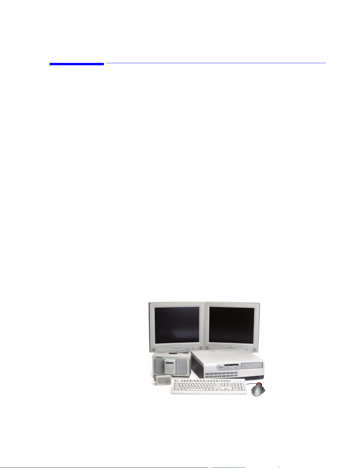
1
Introducing the IntelliVue Information Center System
Overview
The IntelliVue Information Center system running the M3290A Information Center Release
E.01 application software represents a significant advance in patient monitoring through the
integration of a wide range of functionality into a single, standard PC or Server running a
Microsoft® Windows™ Operating System. The Information Center combines the features of
a central monitor -- multipatient waveform and parameter display, alarm annunciation,
multilead arrhythmia monitoring, and ST analysis -- with the patient data review of a clinical
review station to meet the diverse needs of today’s clinical environment.
The Information Center also represents advances in monitoring convenience, flexibility, and
ease-of-use. Display formats, monitoring controls, alarm response, and patient data
presentation are easily configured to suit user preferences and optimize user performance.
Information System functionality can also be purchased in a variety of ways to tailor the
system to specific clinical needs and applications.
A Database Server can be connected to the IntelliVue Clinical Network for storing patient
data obtained from patient monitors connected to Information Centers. Patient data are
transmitted through the Network to the Database Server for storage, analysis, and review. The
M3154 Database Server can store data for up to 128 patients, which can be viewed by all
M3155 Information Centers on the Network and by 8 additional Network connected M3151
Information Center Clients. The M3169 Small Database Server can store data for up to 48
patients, which can be viewed by up to 3 M3155 Information Centers on the Network and by
3 additional Network connected M3151 Information Center Clients. Real-time patient
monitoring data can also be overviewed by all Information Centers and Clients on the
Network. A web access option permits viewing stored and viewable recording patient data
from browser equipped PCs via the hospital’s intranet.
Chapter 1 overviews the system in the following sections.
Patient Monitors page 1-14
Features page 1-17
Components and Options page 1-42
Figure 1-1 Typical Dual Display Information Center System
Introducing the IntelliVue Information Center System 1-1
Page 26

Information Center System
Information Center System
The Information Center system consists of medical software executing on a standard
workstation running a Windows Operating System.
Warning Components, topologies, and configurations specified by Philips have been optimized and
test to meet a variety of patient monitoring standards. Hardware and software products
not supplied by Philips as part of an Information Center system are not approved or
supported by Philips for use with Information Center and Clinical Network/Database
Server systems.
M3150 Information Center Local Database
Independent
Operation
Standard
Components
The Information Center can operate as independent (stand-alone) central monitors. When
operating independently, patient data are stored in the Information Center PC. Stored patient
monitoring data can only be reviewed on the Information Center on which it was obtained.
Real-time patient monitoring data, however, can be viewed by any Information Center
connected to the same CareNet switch, but not Information Centers on other CareNet
switches.
Each M3150 Information Center includes the following standard components:
• Compaq D510 processing unit with:
– hard disk drive
– floppy disk drive
– CD ROM drive
– Windows XP Operating System software
– Information Center application software
– audio card
– SDN interface card
– 10BT/100TX Ethernet Network adapter card
• Keyboard
•Mouse
• External Speaker
• Uninterruptible Power Supply (UPS)
The current workstation for the Information Center is the Compaq D510 PC shown in Figure
1-2.
Note The specific workstation, display, UPS, and printer shipped with each system may vary with
date of purchase as newer models are substituted when they become available. Displays are
1-2 Introducing the IntelliVue Information Center System
Page 27
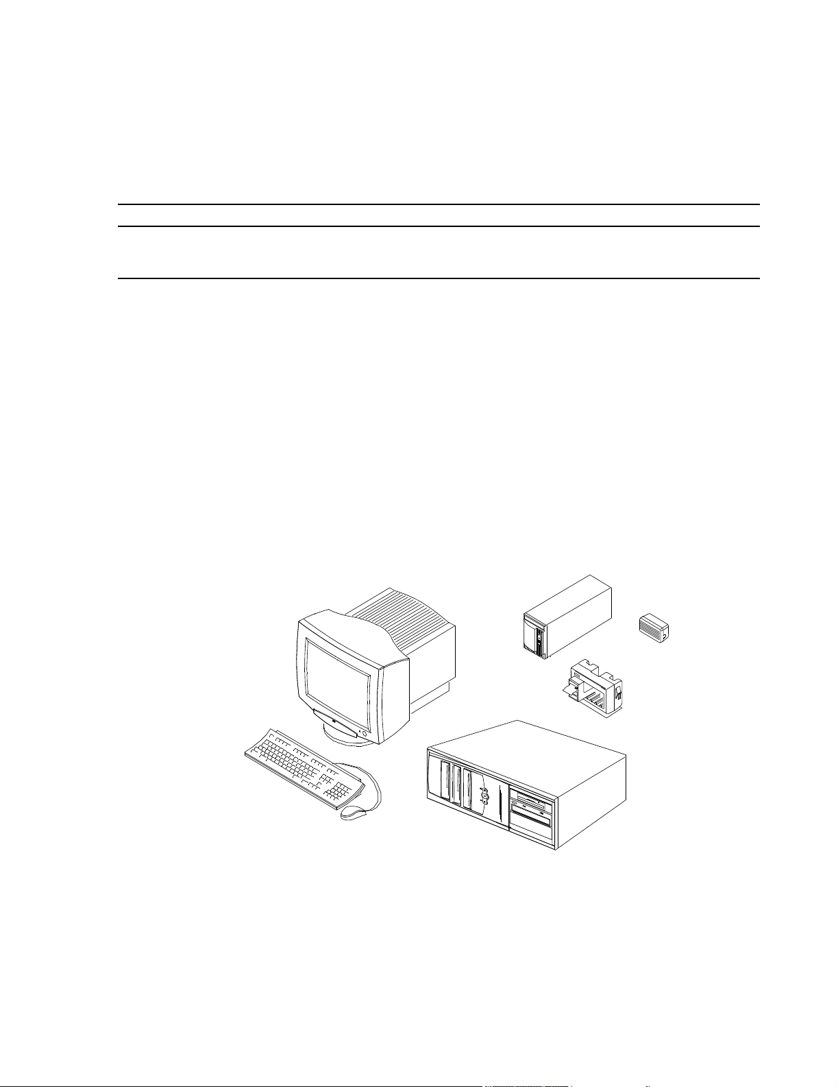
Information Center System
ordered to match customer requirements. Throughout this Manual, only general descriptions of
devices subject to change will be provided. For more detailed information, see the device
manuals.
Note Displays are sold separately. Philips will not install displays not supplied by Philips and cannot
guarantee their compliance with the EMC Directive.
Optional
Components
The following optional components are also available - refer to the option list at the end of
this section:
• Video Card for second display (Information Centers and Clients only)
• Video splitters (2-way and 6-way) for remote, slave displays
• Displays - CRT ( medium & large) and Flat Panel (large)
• 2-Channel Recorder System
• 4-Channel Recorder
• LaserJet printer
• Printer Hub for connecting up to 4 (Local Database) Information Centers to a single
printer
• Trackball
• Mounting hardware for PCs, displays, and UPS
• Interconnecting cables of various lengths
Medium CRT
Color Display
UPS
Speaker
2 Channel
Recorder
Keyboard
18.5
Mouse
PC
Figure 1-2 Basic Information Center Workstation
Introducing the IntelliVue Information Center System
1-3
Page 28

Information Center System
M3155 Information Center Network Database
Standard
Components
The M3155 Information Center connects to the Database Server. Patient data are stored in the
connected Database Server (either the M3154 or M3169). Patient monitoring data can only be
reviewed by any other M3155 Information Center on the network that is connected to the
same Database Server.
Each M3155 Information Center includes the following standard components:
• Compaq D510 processing unit with:
– hard disk drive
– floppy disk drive
– CD ROM drive
– Windows XP Operating System software
– Information Center application software
– audio card
– SDN interface card
– 10BT/100TX Ethernet Network adapter card
• Keyboard
•Mouse
• External Speaker
• Uninterruptible Power Supply (UPS)
The current workstation for the Information Center is the Compaq D510 PC shown in Figure
1-2.
Note The specific workstation, display, UPS, and printer shipped with each system may vary with
date of purchase as newer models are substituted when they become available. Displays are
ordered to match customer requirements. Throughout this Manual, only general descriptions of
devices subject to change will be provided. For more detailed information, see the device
manuals.
Note Displays are sold separately. Philips will not install displays not supplied by Philips and cannot
guarantee their compliance with the EMC Directive.
Optional
Components
The following optional components are also available - refer to the option list at the end of this section:
• Video Card for second display (Information Centers and Clients only)
• Video splitters (2-way and 6-way) for remote, slave displays
• Displays - CRT (medium & large) and Flat Panel (large)
• 2-Channel Recorder System
• 4-Channel Recorder
• HP LaserJet printer
• Trackball
• Mounting hardware for PCs, displays, and UPS
• Interconnecting cables of various lengths
1-4 Introducing the IntelliVue Information Center System
Page 29

M3151 Information Center Client
Information Center System
Standard
Components
Note Displays are sold separately. Philips will not install displays not supplied by Philips and cannot
Optional
Components
Each Information Center Client includes the following standard components:
• Compaq D510 processing unit with:
– hard disk drive
– floppy disk drive
– CD ROM drive
– Windows XP Operating System software
– Information Center application software
– audio card
– SDN interface card
• Keyboard
•Mouse
• External Speaker
• Uninterruptible Power Supply (UPS)
The current workstation for the Information Center Client is the Compaq D510 PC shown in
Figure 1-3.
guarantee their compliance with the EMC Directive.
The following optional components are also available - refer to the option list at the end of
this section:
• Video Card for second display
• Video splitters (2-way and 6-way) for remote, slave displays
• Displays - CRT ( medium & large) and Flat Panel (large)
• 2-Channel Recorder System
• 4-Channel Recorder
• HP LaserJet printer
• Trackball
• Mounting hardware for PCs, displays, and UPS
• Interconnecting cables of various lengths
Introducing the IntelliVue Information Center System
1-5
Page 30
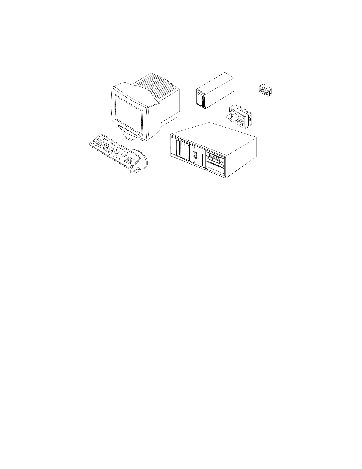
Information Center System
M3170 Patient Link
Medium CRT
Color Display
Keyboard
18.5
Mouse
PC
UPS
Speaker
2 Channel
Recorder
Figure 1-3 Basic Information Center Client Workstation
The M3170 Patient Link operates as a M3150 Information Center local database without a
display. The M3170 Patient Link provides a central location for bedside recordings and
reports initiated from SDN hardwired bedsides, M2/3/4 bedsides and IntelliVue Patient
Monitors. In addition, the Patient Link provides support for bed to bed overview and alarm
reflection for M3/4 bedsides and IntelliVue Patient Monitors. Patient Link cannot be used
with Telemetry besides. Patient names are not included on the recording annotation
Standard
Components
M3170 Patient Link does not have a clinical user interface (i.e. there is no display connected).
It does not generate alert sounds and relies on the bedside monitor for visual and auditory
alarm notification. All Clinical User Settings and Patient Settings are set to the factory
defaults and cannot be changed. The only configuration changes that can be applied are those
in the Config Wizard.
Each M3170 Patient Link includes the following standard components:
• Compaq D510 processing unit with:
– hard disk drive
– floppy disk drive
– CD ROM drive
– keyboard and mouse (required for installation and support only)
– Windows XP Operating System software
– Information Center application software
– SDN interface card
– 10BT/100TX Ethernet Network adapter card
• 2-Channel Recorder System
• Uninterruptible Power Supply (UPS)
1-6 Introducing the IntelliVue Information Center System
Page 31

The current workstation for Patient Link is shown in Figure 1-2.
UPS
PC
Figure 1-4 Basic Patient Link Workstation
Information Center System
2 Channel
Recorder
M3154 Database Server
The M3154 Database Server is a Server that provides database storage of patient monitoring
data for all devices on the Network. Information Center application software provides for
storage of up to 96 hours of patient monitoring data (full disclosure waveforms, physiologic
parameters, alarms, multi-lead arrhythmia, ST segments, and EASI 12-lead presentations)
from 128 patients. Patient monitoring data, including events and trends, can be reviewed by
any M3155 Information Center or M3151 Client on the Network.
The Information Center Web Access option permits viewing of all patient data stored on the
Server (waves, alarms, events, ST segments, trends, and viewable recording strip data) by PCs
on the hospital’s HIS intranet. Up to 100 simultaneous users can access stored patient data
using standard web browsers -- Internet Explorer (Release 5.0 or greater) and Netscape
(Release 4.7 or greater).
Standard components for the M3154 Database Server are shown in Figure 1-5 and include
the following:
• Server with:
– hard disk drive
– floppy disk drive
– CD ROM and disk drives
– modem (US/Canada only)
– 10BT/100TX Ethernet Network adapter card (for Clinical Network access)
– 10BT/100TX Ethernet Network adapter card (for connection to Hospital LAN)
• keyboard
•mouse
•UPS
• Microsoft Windows 2000 Operating System
• Information Center application software with database storage of the following data for
up to 128 patients:
– 24 hours of full disclosure waveforms (4 waveforms per patient) and physiologic
parameters
– 150, 30 second alarm records and saved strips, 4 waves per record
– 24 hours of trends with 1 minute of resolution
– 24 hours of ST segments
– 24 hours of events with 1 hour strip function
Options for the M3154 Database Server are:
• 48, 72, or 96 hours of patient data storage per patient
Introducing the IntelliVue Information Center System
1-7
Page 32

Repeater
Information Center System
• Clinical Network connectivity for 2, 4, 6, or 8 Information Centers
• Web access to stored patient data from browser equipped PCs on the hospital LAN
• Export of derived 12-Lead information for EASI 12-Lead IntelliVue Patient Monitor
data in XML format
• HL7 formatted messages containing Information Center collected data can be output to
an external HL7 compliant receiver
• Alert Data Export
• Interface to Philips/Zymed Holter for Windows
Display
UPS
Large Network Database System
M3169 Small Database Server
Keyboard
Up to ten M3154 Database Servers can be interconnected on the hospital LAN. This
connectivity provides Information Centers with the ability to transfer patient data to a clinical
unit outside of its Database Server. The clinical operator selects a destination clinical unit
when discharging. Retrospective data, near real-time waves, parameters, and alarms for
patients across care units that are on separate database servers can also be reviewed. If a
M2385 Application Server is present, web-based applications can be displayed on the
Information Centers.
The M3169 Database Server is a Server that provides database storage of patient monitoring
data for all devices on the Network. Information Center application software provides for
storage of 48 hours of patient monitoring data (full disclosure waveforms, physiologic
parameters, alarms, multi-lead arrhythmia, ST segments, and EASI 12-lead presentations)
from 48 patients. Patient monitoring data, including events and trends, can be reviewed by up
to 3 M3155 Information Centers and 3 Clients on the Network.
Standard components for the M3169 Database Server are shown in Figure 1-6 and include
the following:
• PC with:
– hard disk drive
– floppy disk drive
– CD ROM and disk drives
– 10BT/100TX Ethernet Network adapter card
• keyboard
•mouse
•UPS
Mouse
Figure 1-5 M3154 Database Server
Server
1-8 Introducing the IntelliVue Information Center System
Page 33

Information Center System
• Microsoft Windows XP Operating System
• Information Center application software with database storage of the following data for up to 48
patients:
– 24 hours of full disclosure waveforms (4 waveforms per patient) and physiologic
parameters
– 150, 30 second alarm records and saved strips, 4 waves per record
– 24 hours of trends with 1 minute of resolution
– 24 hours of ST segments
– 24 hours of events with 1 hour strip function
Options for the Small Database Server are:
• 48 hours of patient data storage per patient
• Clinical Network connectivity for 1, 2, or 3 Information Centers
Display
UPS
Keyboard
Mouse
PC
Figure 1-6 M3169 Database Server
Introducing the IntelliVue Information Center System
1-9
Page 34

Topologies
Topol ogies
Table 1-1 presents the applications available supported in each system configuration and Figure 1-7
and Figure 1-8 show these topologies. Note that these figures do not show the full system
capabilities.
Table 1-1. Topologies
EASI
Alert Data
Export
HL7 12-Lead
1
Holter
Export
Review
Apps
Web Access
Pt Data
6
Xfer
Bed-Bed
Overview
Browser
M3150 Information Center System (Local Database)
Information Center Local
Yes Yes Yes Yes
2
No Yes
3
No No No No
Database
IntelliVue Patient Monitor No No No Yes No No No No Yes No
SDN Patient Monitor No No No No No No No No Yes No
M3150 Information Center Local Database System with M2385 Application Server
Information Center Local
Yes Yes Yes Yes
2
No Yes
3
No No No Yes
Database
IntelliVue Patient Monitor No No No Yes No No No No Yes Yes
SDN Patient Monitor No No No No No No No No Yes No
M3155 Information Center System (Networked with M3169 Small Database Server)
Information Center
Yes Yes Yes Yes Yes Yes
3
No No No Yes
Networked
Information Center Client Yes No n/a Yes Yes Yes
3
No No No Yes
M3169 Database Server Yes No Yes Yes Yes Yes No No No No
IntelliVue Patient Monitor Yes No No Yes No Yes
4
No No Yes Yes
4
4
4
4
SDN Patient Monitor Yes No No No No No No No Yes No
M3155 Information Center System (Networked with M3154 Database Server)
Information Center
Yes Yes Yes Yes Yes Yes
3
Yes
4
Yes
5
No Yes
Networked
Information Center Client Yes Yes No Yes Yes Yes
3
M3154 Database Server Yes Yes Yes Yes Yes Yes Yes Yes
IntelliVue Patient Monitor Yes No No Yes No Yes
4
Yes
Yes
4
4
5
Yes
5
No Yes
No No
No Yes Yes
SDN Patient Monitor Yes No No No No No No No Yes No
1
Any of the following functionality: Capture, Interpretation, Display via Review
Applications, or Export
2
Export to floppy disk only
1-10 Introducing the IntelliVue Information Center System
4
4
4
Page 35

3
Native only
4
Served by the Application Server
5
Single or multiple M3154 Database Servers
6
Across multiple M3154 Database Servers
Topologies
IntelliVue Clinical Network
Wired
IntelliVue Patient Monitor
M3155
Information
Center
M3155
Information
Center
10 Mbit/s
16 patients
16 patients
M2385 Application Server
100 Mbit/s
Network Switch
128 patients
(max)
100 Mbit/s
100 Mbit/s
10 Mbit/s
100 Mbit/s
M3154
Database Server
18.5
16 patients
M3151
Clients
16 patients
M3151
Clients
16 patients
18.5
HIS LAN for
web access
HIS LAN for
web access
LaserJet Printers
Figure 1-7 Typical Basic System Topology
Introducing the IntelliVue Information Center System
1-11
Page 36

Topologies
CMSs
24s
CMSs
Tel e m et r y s
Wired
M2/M3/M4 Monitor
Wired
IntelliVue Patient Monitor
Wireless IntelliVue &
M3/M4 Monitors*
CareNet
16 patients
CareNet
Switch
16 patients
CareNet
Switch
LaserJet Printer
M3155
Information
Center
M3155
Information
Center
M3155 Information Center
M3155 Information Center
10 Mbit/s
Access Points
Access Points
16 patients
16 patients
M3185 Clinical Network
LaserJet Printers
10 Mbit/s
100 Mbit/s
100 Mbit/s
Network Switch
100 Mbit/s
100 Mbit/s
Network Switch
M2385
Application Server
100 Mbit/s
128 patients
(max)
10 Mbit/s
LaserJet
Printer
18.5
100 Mbit/s
12 patients
M3151
Clients
12 patients
12 patients
M3151
Clients
12 patients
100 Mbit/s
M3154
Database Server
M3151
Clients
16 patients
M3151
Clients
16 patients
18.5
HIS LAN for
web access
HIS LAN for
web access
100 Mbit/s
Figure 1-8 Typical Complex System Topology
1-12 Introducing the IntelliVue Information Center System
Page 37

Philips CareNet
Information Centers are designed to operate on Philips CareNet network, consisting of the
Serial Distribution Network (SDN) and the Philips System Communications Controller (PCC/
SCC) or the CareNet Controller. See Figure 1-9.
The Philips CareNet is a local area communications network designed to share patient
physiological waves, parameters, and other data among bedside monitors, recorders, printers,
and other computer systems.
The PCC/SCC is the active device of the SDN, providing communications links to
instruments connected to the SDN and controlling data flow, timing, synchronization, and
distribution throughout the network. The Information Center processing unit contains an SDN
interface card for communication with the SCC and its SDN networked instruments.
Philips CareNet
Network Cabling
Patient Monitors
Telemetry
Monitor
Bedside
Monitors
Network cabling between the SCC and wall boxes for system instrument connections (bedside
monitors, central stations, etc.) can be Philips’ proprietary, shielded, System Distribution
Cable (SDC) or standard LAN, Category 5, Unshielded Twisted Pair (UTP) cable.
PCC/SCC
Switch
Figure 1-9 Typical Information Center Monitoring System Network
Information Center System
Processing Unit
Color Display
Keyboard
2-Channel Recorder
Mouse
4 Channel Recorder
(Optional)
Printer (optional)
Speaker
UPS
Introducing the IntelliVue Information Center System
1-13
Page 38

Patient Monitors
Patient Monitors
The Information Center is designed to be compatible with recent Philips medical systems bedside monitors, telemetry mainframes, central stations, and other computer systems
compatible with Philips’ Serial Distribution Network. It can both send data to and receive data
from SDN compatible instruments, recorders, and printers.
CMS 2002 Patient
Monitoring System
M3/M4
Wireless Patient Monitors
V24
Patient Monitor
IntelliVue Patient Monitors
Philips Telemetry
System
M2/M3/M4
Wired Patient Monitors
Figure 1-10 Information Center Compatible Bedside and Telemetry Monitors
Table 1-2. Patient Monitors Compatible with Software Rel. E.01 and EASI
Product Name Product Number
IntelliVue Patient Monitor M8005A/M8007A/
M8010A
Component Monitoring System M1175/76/86A C and later C and later
Philips 24 Patient Monitor M1205A all C and later
Compact Configured Monitor 78352A/C,
78353B, 78354A/C
78833B, 78834A/C
Digital UHF Telemetry M1403A/J E.0 E.0
Philips Telemetry System M2600A E.0 and later E.0 and later
Software Release
Req’d for Rel. E.01
A.10 and later A.10 and later
all Not supported
Software Release
Req’d for EASI
1-14 Introducing the IntelliVue Information Center System
Page 39

Patient Monitors
Table 1-2. Patient Monitors Compatible with Software Rel. E.01 and EASI
Product Name Product Number
TeleMon A.0 and later
Philips M2/M3/M4 Wired Monitor
M3/M4 Wireless Patient Monitor
M2/M3/M4 Measurement Server
M3046A
M3046A #J20
M3000A
Software Release
Req’d for Rel. E.01
D.0 and later
C.04 and later
Software Release
Req’d for EASI
E.0
Note M2350/60A CCMs (release B.03.13) that monitor telemetry with release 2.x cannot connect to
the same Serial Communications Controller (SCC) as Information Center systems (release C.0
and later).
Table 1-3. Information Center Compatible Software
Product Name Software Release Req’d for Rel. E.01
TraceMaster A.04 and later
Holter 2.6 and later
Application Server A.01 and later
Emergin Wireless Office Alarm Messenger 5.0 or greater
The following Philips equipment is not compatible with Information Center systems.
Table 1-4. Information Center Non-Compatible Equipment
Product Name Product Number Software Release
Monitor Terminal 78534A/B/C all
Comprehensive Monitor Terminal 78532A/B all
Compact Configured Monitor 78352B, 78353A, 78354B all
Digital UHF Telemetry M1403A all Releases prior to E.01
SDN Arrhythmia System 78720A/B all
Central Monitor 78560 all
Patient Information Center 78501/502/504/508/509 all
Clinical Event Review M1251A all
Note: All Information Centers and Database Servers must be upgraded to the same Software Release
Table 1-5. Information Center Non-Compatible PC/Server Models
PC Model Number
D4796N Kayak XA Not supported Not supported Not supported Not supported
D4354N Vectra XU Not supported Not supported Not supported Not supported
D4367N Vectra XU Supported Not supported Not supported Not supported
D4692N Kayak XU Supported Not supported Not supported Not supported
Software Release
Rel. D.0
Software Release
Rel D.01
Software Release
Rel E
Software Release
Rel E.01
Introducing the IntelliVue Information Center System
1-15
Page 40

Patient Monitors
PC Model Number
D5765T Kayak XA-s Supported Supported Supported Not Supported
D6723T Kayak XA Supported Supported Supported Not Supported
D6731T Kayak XA Supported Supported Supported Not Supported
LH3 NetServer Supported Supported Supported Not Supported
Software Release
Rel. D.0
Software Release
Rel D.01
Software Release
Rel E
Software Release
Rel E.01
1-16 Introducing the IntelliVue Information Center System
Page 41

Features
Features
The Information Center is the central monitoring station that provides multipatient display of
real time patient waveforms and physiologic parameters, annunciation of alarms and a wide
variety of patient data storage and review functions, including full disclosure waves and
parameters, alarms, ST segments, events, trends, and EASI 12-lead presentations. Patient
monitoring features of the Information Center central monitor are described in detail in the
Information Center Instructions for Use and discussed briefly below.
Main Screen The Main Screen of the Information Center is the primary patient monitoring screen. It can
display up to 16 patients and 3 waves per patient with a maximum of 24 waves per screen ( 32
waveforms for one display, dual display recommended). The arrangement of Patient Sectors
can be designed to suit user preferences with up to 2 columns and 8 rows, and the patient’s
name can be displayed in a variety of formats.
Patient data can also be color coded for easy identification. Colors for waves and parameters
can be individually selected using color pallets available in display configuration windows.
Patient Sectors in alarm are also highlighted in color for immediate recognition of alarm
conditions and their severity. The date and time and messages of Recorder and Printer status
also appear at the top of the Main Screen.
Figure 1-11 Main Screen
Introducing the IntelliVue Information Center System
1-17
Page 42

Features
Patient Window
Additional data for each patient can be obtained in a more detailed Patient Window.
Positioning the mouse cursor in a patient sector causes a Patient Window button to appear.
Clicking on the Patient Window button brings up the Patient Window for that patient. The
Patient Window can display up to 4 waves and 12 parameters for a single patient.
For an Information Center with a single display, the Main Screen resizes to make room for the
Patient Window. For systems with a second display, the Main Screen remains in the first
display and the Patient Window appears in the second display or the Main Screen can also
utilize both displays. The Patient Window in a 2-display system can display up to 7 waves for
a single patient.
In dual display systems, both displays can have patient sectors when Main Screen is active.
For example, for a 16-patient central, the Main Screen of each display would include 8
sectors. This feature is available for 8, 12, and 16-patient centrals.When an application
window is open, all the sectors move to one display, and the second display has the fullscreen application window. To remove the application window, click the
Buttons for accessing additional information and changing monitoring parameters are also
provided at the bottom of the Patient Window.
Main Screen button
Figure 1-12 Main Screen with Patient Window
1-18 Introducing the IntelliVue Information Center System
Page 43

Features
All Controls Window
Patient
Management
Alarm
Management
and Setup
The main control window for an Information Center is titled All Controls. It is obtained by
clicking on the All Controls button in the Patient Window. The All Controls window provides
control buttons for four major categories of Information Center applications:
• Patient Management
• Alarm Management and Setup
• Patient Data Review
• Configuration and Support
The first three categories -- Patient Management, Alarm Management and Setup, and
Patient Data Review -- are intended for clinical users. Their purpose and operation are
described in detail in the IntelliVue Information Center Instructions for Use. Their
general functions are the following:
The Patient Management menu provides buttons for managing the Patient Sectors. These
include buttons for patient admission, discharge, and bed transfer, buttons for selecting which
waves and parameters to display and store in the patient’s data file, and a standby button with
a selection of standby messages to display.
The Alarm Management and Setup menu provides buttons for setting up the arrhythmia
and ST Segment configurations (alarms and waves) for each patient, setting the volume of the
alarm tones, and selecting telemetry monitor frequencies.
Patient Data
Review
Note Not all features may have been purchased. Not all features are available in local mode.
Configuration
and Support
The Patient Data Review menu provides buttons to access stored patient data for review of
trends, alarms, events, full disclosure waves, and ST Segments.
The Configuration and Support menu has applications for clinical users, nurse managers, and
service personnel. Some of these applications are password protected to prevent accidental
system or network changes by unauthorized users that might disrupt monitoring.
Support Info is available to all clinical users, nurse managers, and service personnel and is
not password connected. Clicking on the Support Info button brings up the Purchased Options
and Support Information window, which is Read Only. This window contains a variety of
useful information about the Information Center or Client that may be needed when a problem
occurs. Users can access this window to find out who to contact and basic facts about this
device that may be requested by service personnel.
Status Log is available to all clinical users and is not password protected. Status Log accesses
a Status Log window that provides information on the operational status of all devices
connected to the network. It can be used for quick identification and reporting of device
problems.
Unit Settings is password protected for use by nurse managers. Unit Settings accesses unit
wide configuration controls. These are for persons responsible for setting unit wide
configurations for monitoring patients. Access to the Unit Settings window requires a User
Password to proceed.
Introducing the IntelliVue Information Center System
1-19
Page 44

Features
Caution The default Unit Settings Password is philips. This can be changed to a user-
specified password via the service menu. See “Change Units Password” on page 7-76. It
should only be used by persons responsible for setting unit wide configurations for
monitoring patients.
Patient Data Storage
Patient Data
Review
The M3154 Database Server can store up to 96 hours of patient data for up to 128 active
patients, e.g. 8 Information Centers with 16 patients each. The M3169 Small Database Server
can store up to 48 hours of patient data for up to 48 active patients, e.g. 3 Information
Centers with 16 patients each. Patient data are kept on the Server until the patient is
discharged. The Server can also store data for up to 32 (4 per Information Center) discharged
or transfer patients per Information Center for possible readmission after they have been
discharged. Hence the Server can store up to 96 hours of patient data (depending on which
Database Server) for an additional 32 transfer patients.
The 96 hours of stored patient data include:
• full disclosure waves, 4 waveforms per patient
• physiologic parameters
• One hundred and fifty 30 second alarm records and saved strips, 4 waves per record
• trends with 1 minute of resolution
•ST segments
• events with 1 hour strip function
Stored data for all patients on the Server are available for review by any Information Center
and Client on the Network. Full Control, Read Only, or No Access to patient data stored on
the Server is controlled at the Information Center supplying the data. All stored data - full
disclosure waves, alarms events, ST segments, and trends - for each patient can be reviewed.
Features of Patient Data Review applications are the following:
Wave Review:
• continuous full disclosure of up to 4 configurable waves per patient
• 1 minute to 60 minutes wave duration per screen:
single display - 1 wave for up to 30 minutes duration
dual display - 4 waves for up to 60 minutes duration
• timeline, trend, and event navigators for fast searches and greater context
• strip reports
Alarm Review:
• 30 s compressed waveforms of alarm or saved strip events
• up to 4 waveforms per event
• simultaneous display of alarm events:
single display - 5 alarm strips
dual display - 10 alarm strips
• search by alarm severity
• interval measurement
• relabel alarm name
Event Review:
1-20 Introducing the IntelliVue Information Center System
Page 45

• 10 configurable groups, up to 5 alarm criteria per group
• strip displayed for verification of event criteria
• total occurrences of alarms calculated and displayed in 1, 4, 8, 12, and 24 hour time
scales
ST Review:
• ECG complexes stored at 1 minute resolution for connected patients
• 50 mm/s presentation for increased resolution
• EASI 12-lead presentations
• superimposition of up to 4 sets of complexes with ST values
• trend, event and ST topology navigators for fast searches and greater context
Trend Review:
• tabular display of physiological parameters
• graphical presentation at 1 min. resolution using bivariate trend plots
• 10 configurable groups with 5 bivariate trend plots, 10 parameters per group
• exact parameters displayed for cursor time location
• simultaneous display of trend plots:
single display - 2 trend plots
dual display - 5 trend plots
• trends displayed in 1, 4, 8, 12, and 24 hour time scales
Features
EASI 12 Lead Review:
• retrospective review of 12 derived leads
• 2.5 s to 10 s snippets
• 3 x 4, 6 x 2, and 12 x 1 (row by column) display and reports (12 x 1 not available on
single display)
• EASI leads from M3-E patient monitors are not available
Note Detailed descriptions of patient data review are given in the Information Center
Instructions for Use.
Alert Data
Export
An alerting system is available (in North America only) for secondary notification of patient
alarms. Information Center systems with the Alert Data Export option acquires patient alarm
data from the bedside or the telemetry monitoring system and automatically relays it in
textual format (via a LAN connection) to a receiving device. No waveform data is sent. The
receiving device is configured via the Config Wizard. See “Network Configuration” on
page 6-24.
Note Since all alarm data is automatically sent to the receiving device no user intervention is
required at the Information Center. For information on using the receiving device see the
documentation that comes with the device.
Warning Alert Data Export is a secondary alarm notification system. It is not intended for
primary notification of alarms, physiological, or demographic data. Receipt by the
Introducing the IntelliVue Information Center System
1-21
Page 46

Features
external software device of alarms is not confirmed and delivery to the end device is not
guaranteed. Clinicians using Alert Data Export must remain within monitoring distance
of the primary alarm notification device.
The primary alarm notification device is either the bedside monitor (if present) or the
Information Center.
All alarms (red, yellow, and INOPs) for all beds being monitored by the Information Center
are automatically exported in textual format to the receiving device. Alarms are sent in the
order in which they occur. So, if a yellow alarm occurred for one bed immediately followed
by a red alarm for another bed the yellow alarm is sent first followed by the red. The format
of the alarm text sent is bed label:: alarm level (high, medium, low priority) and alarm text
(for example Bed4::*** Asystole). If the Information Center is configured to have alarm
reminders, the format of the alarm reminders sent is, bed label:reminder label:alarm level
(high, medium, low priority) and alarm text, (for example, Bed4:REM:*** Asystole).
If connection between the Information Center and Alert Data Export receiving device is lost
for any reason no alarms are sent and the message “Alarm paging not available” displays in
the Information Center system message area.
Data Reliability The M3154 Database Server utilizes RAID (Redundant Array of Independent Disks)
technology to assure fault tolerant data collection and storage in the event of disk failure. Data
are written to multiple disks simultaneously to provide data storage redundancy. If the Server
or Network fails for any reason, Information Centers revert to local database operation so that
patient monitoring data collection are maintained. The M3169 Database Server does not use
RAID.
Remote Access Error Logs, showing all events that occur in each device on the Network when it starts and as
it operates and giving device operational status, can be accessed during patient monitoring via
a modem in the Server. This permits efficient troubleshooting and problem identification
without disruption to patient care.
Information
Center Web
Access
The Information Center Web provides remote, read-only access to physiologic patient data
that is resident on an M3154 Database Server. Patient Data Review applications on the
M3154 Database Server can be accessed via the hospital’s HIS intranet using standard web
browsers, such as Internet Explorer and Netscape. In a Large network system, up to 100
simultaneous users can view stored waves, alarms, events, ST segments, trends, and viewable
recording strip data for each patient in the M3154 Database Server. Data are accessed by a
configurable log-on procedure using the hostname of the Database Server or the IP Address
of the Web LAN card in the Server as the URL to access the Information Center WEB
TM
Login window shown in Figure 1-13.
Web access is not available on the M3169 Small Database Server.
Note The URL can also be the Host name of the Server if the hospital LAN’s DNS (Dynamic Name
Server) is properly configured. However, if there are multiple Servers on the Network, each
Server’s Host name must be unique.
1-22 Introducing the IntelliVue Information Center System
Page 47

Features
Figure 1-13 Login Window for Information Center Web
A user selected Password is then required to access the Select Patient window for selecting
a patient’s stored data. See Figure 1-14. Selecting a patient from the Patient List and
clicking on the type of data desired displays the stored data for that patient.
Note Part of the Web configuration procedure permits specifying which PCs on the hospital’s
intranet can and cannot access the Server and review patient data
Note All Philips Patient Monitoring products that operate in a LAN environment undergo industry-
standard virus checking as part of the product manufacturing process. If installed as specified,
the Information Center will not introduce a virus onto the hospital LAN. In order to allow the
level of access desired by users while ensuring viruses do not affect the operation of the
Information Center product, it is imperative that hospitals are vigilant in maintaining a virusfree intranet. This is the responsibility of the hospital, not Philips Medical Systems.
Introducing the IntelliVue Information Center System
1-23
Page 48

Features
Figure 1-14 Web Patient Data Selection window
Service A keyboard, mouse are provided with the Server for a variety of Service functions (a display
is ordered separately) -- system configuration, network maintenance, and troubleshooting.
When the Server initializes, an ENTER PASSWORD window appears with an Enter
Service Password: field. Entering the Service Password and clicking OK displays the
Service window shown in Figure 1-15.
Notes The Service Password is m3150. It is to be used by service personnel who are properly
trained and assigned to servicing Philips systems. It is the same Service Password as for
Information Centers and Clients. All Service tools are in English only.
Figure 1-15 Service Window showing the Configuration Menu
Depending on the operating system, the service applications, when opened, may display over
the Main Screen. If this happens, the mouse can be used move the window. Another operating
system behavior is to “hide” the application window when it is inactive. If an application is
open, but not shown in the screen, press Alt + Tab simultaneously to select the application
and bring it to the front.
1-24 Introducing the IntelliVue Information Center System
Page 49

Features
The Service Menu contains the following applications:
• Support Logs that provide information on the operational history and condition of
Philips devices and networks.
• Diagnostics tools to help diagnose and troubleshoot Philips system problems for both
Philips and Window applications.
• Configuration applications for configuring the network and devices connected to it.
• Other Services that provide Windows configuration tools and remote access capability
• Shutdown for the controlled shutdown of Philips application software and access to the
Windows Main Menu.
• Maintenance applications for troubleshooting the network and the connected devices.
Each heading has a menu of application options, as shown in Figure 1-15 for Configuration.
Clicking on the heading name displays the menu. Items with an arrow (>) to the right have
sub menus.
Note The Read Only Config Wizard application in the Configuration menu permits viewing of
network and device settings while all devices are in monitoring mode, but settings cannot
be changed.
Configuration Configuration of the Information Center system hardware and software (including the
Network and many of the Network device parameters) is accomplished through a variety of
configuration windows. Configuration is facilitated by a Config Wizard, which
automatically sequences through the configuration windows in the required order. The Config
Wizard is automatically initiated during installation of software, but it can also be accessed
directly from the Configuration menu. See Figure 1-15.
Warning When the !Config Wizard runs on the Database Server, all Information Centers and Clients on
the Network will reboot and go into local database mode and no patient data will be stored by
the Server.
Warning Service Menu items with an exclamation point (!) preceding them only run when the
Information Center or Client is in non-monitoring mode, during which no patient monitoring
can occur.
The following types of configurations - system, unit wide, and patient specific - and software
aids are described below.
System
Configuration
Configuration applications for system components and applications are accessed from the
Configuration menu of the Service function of Information Center software. Most of these
configurations are made during initial software installation using the Config Wizard
applications.
Introducing the IntelliVue Information Center System
1-25
Page 50

Features
Help screens are available for each application to assist in the configuration process. The
Config Wizard is also available from the Configuration menu for reconfiguration of specific
parameters after initial software installation. Certain configuration applications are only
available from the Config Wizard.
Patient
Monitoring
Configuration
Note All patient specific settings return to unit wide default settings when a patient is discharged.
Configuration
Archiving and
Restoration
Configuration of patient monitoring applications is also of two types, unit wide default
settings and patient specific settings. Unit wide default settings provide clinical configuration
settings as default values on a unit wide basis for all patients. These can be overridden by
clinical staff, however, to tailor monitoring applications to the needs of a specific patient.
• Unit Wide Default Settings - Unit wide default settings are made in the Unit Settings
function of the Configuration and Support menu of the All Controls window. This
window provides for setting unit wide default values for alarms, patient data review,
output devices (recorder, display, sound volume), and telemetry frequencies. As noted
earlier, unit wide configuration controls are protected by a Unit Settings Password.
Descriptions of unit wide configurations and patient specific configurations are
described in the Information Center Instructions for Use.
• Patient Specific Configurations - Unit wide default settings and some system
configurations can be changed by the clinician to meet the needs of a specific patient
using the patient monitoring applications accessed from the All Controls window.
Changes in alarm settings, trend groups, stored waves, patient sector displays,
equipment assignment, etc. can be made in these applications.
Configuration settings for system and patient monitoring applications can be archived to a
floppy disk so they are available to reconfigure the system quickly if they are lost or after
software upgrades. These archiving and restoration features are available from the
Configuration menu in the Service function.
On-Line Help To assist users in understanding and using Philips applications, extensive on-line Help
features are provided. These Help screens give detailed descriptions of each application,
including how to use its functionality, make configuration settings, and troubleshoot
problems. Three types of Help information are available.
Clinical User Help is accessed from the Help button in the upper right corner of each clinical
application. Clicking on the Help button brings up a clinical user Help window that describes
1-26 Introducing the IntelliVue Information Center System
Page 51

Features
the application. In many cases there are additional descriptions of words or concepts available
by clicking on text in green and underlined. See the Discharge List in Figure 1-16.
Figure 1-16 Typical Clinical User Help Window
Service Help is also available for Service applications and provides application descriptions
and configuration procedures. As with clinical user help, a Help button is provided in the
upper right corner of the application window. Help information from this button is for Philips
applications only. See Figure 1-17.
Figure 1-17 Typical Service Application Help Window
Windows Help is provided as a standard part of Windows software for applications that are
not part of Philips software. These Help screens are accessed from the Help button in the
menu bar in the upper left of the window. See Figure 1-18.
Figure 1-18 Typical Windows Help Window
Introducing the IntelliVue Information Center System
1-27
Page 52

Features
These comprehensive on-line Help features provide quick and readily accessible information
for understanding and properly using the Information Center’s extensive patient monitoring
capability when and where it is needed.
1-28 Introducing the IntelliVue Information Center System
Page 53

Clinical Applications
The Information Center is a patient monitoring central station that provides a wide variety of
clinical monitoring applications. The primary application is the central display of
physiological waveforms and parameters from patients connected to networked bedside and
telemetry monitors. Information Center applications derived from these measured data include
alarm annunciation, arrhythmia analysis, ST segment analysis (for telemetry monitors), and
extensive patient data history review capability.
Clinical Applications
Patient Monitoring
Typical Plug-in
Modules
Information Center application software provides the display of physiologic waves and
parameters for up to 16 patients from bedside and telemetry monitors connected to an
Information Center via the CareNet.
The Information Center can display the outputs of the variety of Plug-in modules that can be
used with Philips’ bedside monitoring systems some sample modules are shown below - refer
to the Information Center Instructions for Use and to Table 1-6.
M1001A
ECG
T
ECG
M1001A/B M1002A/B
ECG ECG/Resp
M1017A
FlO
2
21%CAL
2
M1017A
FIO
2
ECG/RESP
T
M1002A
ECG
RESP
T
tcpO2/tcpCO
M1018A
NBP
M1018A
tcpO2/tcpCO
STAT
T
2
M1006A
PRESS
ZERO
PRESS
M1006A/B
Press
2
T
NBP
T
M1008B
START
NBP
M1008A/B M1012A
NPB CO
SpO2/PLETH
M1030A
SpO
PLETH
M1020A
SpO2/Pleth
STOP
STAT
T
SvO
M1021A
2
SvO
2
M1021A
SvO
M1015A
T
M1012A
C.O.
C.O.
START
M1015A M1016A
Sidestream CO
T
CALFlO
2
TEMP
T
M1029A
TEMP
M1029A M1032A
Temp VueLink
M1016A
CO
T
2
CO
CAL
2
CO
2
VueLink
VueLink
2
M1032A
T
Figure 1-19 Typical Plug-in Modules (not inclusive) Used in Philips Bedside
Monitoring Systems
Note VueLink modules provide SDN interfaces with external monitoring devices. There are three
VueLink module options, each interfacing with a specific device group:
• Stand-alone parameter devices
• Ventilators
• Gas analyzers
Several external devices are supported within each device group.
Introducing the IntelliVue Information Center System
1-29
Page 54

Clinical Applications
Table 1-6. Typical Philips Plug-in Modules
Philips Model Number Module Name Abbrev.
M1001A/B Electrocardiogram ECG
M1002A/B Electrocardiogram/Respiration ECG/Resp
M1006A/B Pressure P
M1008A/B Noninvasive Blood Pressure NPB
M1012A Cardiac Output CO
M1015A Sidestream Carbon Dioxide CO
M1016A Carbon Dioxide CO
M1017A Fractional Inspired Oxygen FIO
M1018A Transcutaneous Partial Pressure of Oxygen and
Carbon Dioxide
M1020A Oxygen Saturation/Plethysmography SpO2/Pleth
M1021A Mixed Venous Oxygen Saturation SvO
M1029A Temperature T
M1032A VueLink
2
2
2
tcpO2/tcpCO
2
2
Waves and
Parameters
The physiological monitoring capability of the Information Center system is given in the
following table. The Philips Module column indicates the Plug-In Module source of the data
Table 1-7. Information Center Patient Monitoring Capability
Philips
Module
ECG ECG Electrocardiogram HR Heart Rate
ECG/
Resp
P ABP Arterial Blood Pressure ABP SYS Arterial Blood Pressure - Systolic
Waves Parameters
PVC Premature Ventricular Contraction
ST ST segment values for up to 6 leads
RESP Respiration RESP Respiration Rate
ABP DIAS Arterial Blood Pressure - Diastolic
ABP MEAN Arterial Blood Pressure - Mean
ART Arterial Pressure ART SYS Arterial Pressure - Systolic
ART DIAS Arterial Pressure - Diastolic
ART MEAN Arterial Pressure - Mean
1-30 Introducing the IntelliVue Information Center System
Page 55

Table 1-7. Information Center Patient Monitoring Capability
Clinical Applications
Philips
Module
P
(cont’d)
Waves Parameters
PAP Pulmonary Arterial Pressure PAP SYS Pulmonary Arterial Pressure - Systolic
PAP DIAS Pulmonary Arterial Pressure - Diastolic
PAP MEAN Pulmonary Arterial Pressure - Mean
AO Aortic Pressure AO SYS Aortic Pressure - Systolic
AO DIAS Aortic Pressure - Diastolic
AO MEAN Aortic Pressure - Mean
LAP Left Atrial Pressure LAP Left Atrial Pressure
RAP Right Atrial Pressure RAP Right Atrial Pressure
CVP Central Venous Pressure CVP Central Venous Pressure
ICP Intercranial Pressure ICP Intercranial Pressure
CPP Cerebral Profusion Pressure
NBP NBP SYS Non-invasive Blood Pressure - Systolic
NBP DIAS Non-invasive Blood Pressure - Diastolic
NBP MEAN Non-invasive Blood Pressure - Mean
CO CO Cardiac Output
Tblood Blood Temperature
CO
2
CO2 Carbon Dioxide AWRR Airway Respiration Rate
ETCO2 End tidal Carbon Dioxide
IMCO2 Inspired Minimum Carbon Dioxide
FIO
2
tcpO
tcpCO
SpO2/
Pleth
SvO
/
2
2
SpO2 Arterial oxygen saturation SpO2 Arterial oxygen saturation
PLETH Plethysmogram PULSE Pulse Rate
2
FIO2 Fractional Inspired oxygen
tcp O2 Transcutaneous partial press. - O2
tcp CO2 Transcutaneous partial press.- CO
SvO2 Mixed venous oxygen saturation
2
T T Temperature
T1-T2 Temperature difference
Tel emetry
Monitoring
The Information Center also displays patient data from Philips Digital Telemetry systems -M1403A/J Digital UHF Telemetry system (software release E.00 and later) and M2600A
Philips Telemetry system. See Figure 1-20.
Note The Information Center can monitor up to 16 patients from two Philips telemetry mainframes
\
without a SCC. See Chapter 2, System Communications Controller.
The M1403A/J Telemetry system provides ECG monitoring of 2 ECG waves with the ability
to view up to 7 leads. M2600A Philips Telemetry provides ECG monitoring of 3 ECG waves
of up to 7 leads. The M2600A also provides SpO
Introducing the IntelliVue Information Center System
measurements. ST Segment analysis is
2
1-31
Page 56

Clinical Applications
available as an option for both systems, but it is not required when used with the Information
Center because the Philips system provides ST Segment analysis of telemetry data as a
standard feature.
M1403A/J Digital UHF
Telemetry System
Figure 1-20 Telemetry Systems for Information Center Monitoring
Alarm Annunciation
Note The Information Center displays alarm events that it detects as well as those generated by
Information Center software also provides extensive alarm annunciation capability and
flexibility. Alarm events are detected by comparing physiological data against preconfigured
limit values. Alarms detected by Information Center software include:
• Arrhythmia alarms (for data from both bedside and telemetry monitors)
• ST Segment alarms (for data from telemetry monitors only)
networked monitors. However, the Information Center only controls alarm limits and on/off
status for alarms that it detects.
M2600 Philips
Telemetry System
Priorities Information Center software prioitizes alarms into 3 levels of severity:
• Red *** life threatening (e.g. Asystole)
• Yellow ** alarm limit exceeded (e.g. high heart rate)
• Cyan inoperative (INOP) condition (e.g. patient leads off)
Annunciation Alarms are announced by the following indicators:
• Patient Sector turns blue (Red and Yellow alarms only)
• Alarm Tone sounds that indicates the alarm severity (no sound for soft INOPs)
• Alarm message is displayed in Patient Sector and Patient Window of the same color
as the alarm.
– For rate alarms, the message indicates:
— parameter in alarm
— maximum or minimum value of that parameter
— alarm limit that was violated (e.g. HR 134>120)
– For event alarms, the message indicates the event that caused the alarm (e.g.
Asystole)
1-32 Introducing the IntelliVue Information Center System
Page 57

Clinical Applications
• ECG recording is generated for preset periods preceding and following the alarm
event (Red and Yellow alarms only)
Figure 1-11 shows a typical Main Screen with patients in alarm. Note that Patient Sector
CCU2 has the alarm message ***TACHY 160>140. Patient Sectors in alarm are backlighted
in blue for easy identification, and the alarm message window is backlighted in the color of
the alarm severity. For example, the CCU2 message shows a red alarm (***) message.
Table 1-8 summarizes the various alarms that can occur, including the corresponding alarm
sound, alarm message location, ECG recording generation, and alarm meaning. Alarm
messages are described in the IntelliVue Information Center Instructions for Use.
Table 1-8. Information Center Alarm Priorities
Alarm Sound Message Recording Meaning
Red (***) Traditional/CareNet
sound: continuous, high-
pitch rapid tone
IEC/ISO sound: repeated
bursts of five rapid highpitch beeps
Yellow (**) Traditional/CareNet
sound: continuous,
medium-pitch tone
IEC/ISO sound: repeated
bursts of three rapid
low-pitch beeps
Yellow (**)
Arrhythmia
Yellow (**)
Nurse Call on
Telemetry
Hard INOP (*) Traditional/CareNet
Soft INOP (*) none On Display
Traditional/CareNet
sound: noncontinuous,
medium pitch tone
(~10s)
IEC/ISO sound: two
rapid low-pitch beeps
Traditional/CareNet
sound: noncontinuous,
medium pitch tone (~8s)
IEC/ISO sound: two
rapid low-pitch beeps
sound: continuous, slow
low-pitch tone
IEC/ISO sound: repeated
bursts of two slow lowpitch beeps
On Display
with ***
On Display
with **
On Display
with **
On Display
with **
On Display
with no *
with no *
Yes Life threatening, e.g.
AYSTOLE
Yes non-arrhythmia alarm limit
violation (except for HR,
which is an Arrhythmia
alarm)
Yes Arrhythmia yellow alarm
detected
Yes Nurse Call button on
telemetry transmitter
depressed and system
configured to alarm
No Inoperative condition that
prevents monitoring, e.g.
LEADS OFF, or has direct
effect on the patient, e.g.
NBP CUFF OVERPRESS
No Inoperative condition that
prevents signal processing,
e.g., NOISY ECG.
Monitoring continues during
this INOP condition.
Arrhythmia Monitoring
In addition to patient monitoring, the Information Center system provides arrhythmia
monitoring for both bedside and telemetry monitored patients. The multi-lead arrhythmia
monitoring algorithm is designed for adult, pediatric, and neonatal patient ECG waveforms
Introducing the IntelliVue Information Center System
1-33
Page 58

Clinical Applications
for heart rate and ventricular arrhythmia. Multi-lead arrhythmia monitoring is performed on
the user-selected primary ECG lead and the secondary ECG lead.
The following arrhythmia monitoring functionality is provided for both standard models of
the Information Center system. For both models, beat annotation and rhythm and ectopic
status messages are provided in the Patient Window.
Basic
Arrhythmia
Enhanced
Arrhythmia
Basic Arrhythmia functionality includes the basic cardiotach functions of heart rate, PVC rate, beat-to-beat heart rate, and the detection of the following 10 alarms:
• Asystole
• Ventricular fibrillation
• Ventricular tachycardia
• Extreme bradycardia
• Extreme tachycardia
• Pacer not capturing
• Pacer not pacing
• PVC/min
• High heart rate
• Low heart rate
Enhanced Arrhythmia adds the following 11 alarms to the Basic Arrhythmia functionality.
• Irregular heart rate
• Nonsustained V-Tach
• Supraventricular Tach
• Ventricular Rhythm
•Run PVCs
•Pair PVCs
• R-on-T PVC
• Multiform PVCs
•Pause
• Ventricular bigeminy
• Ventricular trigeminy
Details of the arrhythmia alarms and user interfaces are provided in the IntelliVue
Information Center Instructions for Use. Details of the arrhythmia algorithm are described
in the Arrhythmia Monitoring Application Note provided in the Documentation CD-ROM
shipped with your system.
1-34 Introducing the IntelliVue Information Center System
Page 59

Clinical Applications
ST Segment Monitoring
Note ST segment analysis for patients monitored by bedside monitors is performed at the bedside
EASI 12-Lead ECG Review and Report
The Information Center system also provides ST segment analysis for adult patients
monitored via telemetry only. ST segments can be analyzed for up to six leads of ECG
monitoring, depending on the type of telemetry monitor and patient cable used, and for both
non-paced and atrially paced patients (but not ventricularly paced patients).
# Cable
Wires
3 1 lead 1 lead
4 up to 6 leads
5 up to 6 leads 2 leads
monitor and is not available on the Information Center.
Details of displayed ST data, ST alarms, and user interfaces are provided in the IntelliVue
Information Center Instructions for Use. Details of the ST Segment algorithm are
described in the ST Segment Monitoring Application Note provided on the Documentation
CDROM.
If the bedside or telemetry system has the EASI 12-Lead capability (a method of deriving 12
ECG Leads using 5 electrodes), the clinician can view all available leads from the Patient
Window - see table below. In addition, the clinician can request a 12-Lead report. Details of
EASI 12-Lead ECG monitoring are provided in the Information Instruction for Use.
Philips
Telemetry
Digital UHF
Telemetry
Patient Data Review
Alarm Review Alarm Review shows the alarm events that have been automatically stored during patient
The Information Center system has extensive patient data review capability. Patient Data
Review windows display patient physiological parameters and alarm events that have been
collected over time from bedside and telemetry monitors. Review windows can be designed in
a variety of formats to facilitate clinician evaluations of patient status and decisions of
diagnosis, prognosis, medication, and patient transfer and discharge.
The following review applications are accessible from the Patient Data Review buttons in
the All Controls window.
monitoring and alarm strips that were saved for each alarm. A typical Alarm Review record
for a single display is shown in Figure 1-21. Stored alarms are those that were configured in
Alarm Management and Setup and have been stored in the alarm history database during
patient monitoring. Up to 50, 30-second alarms can be stored in the standard system and up to
150, 30-second alarms as a purchased option. Each stored alarm includes the date and time,
alarm text, and a 30-second compressed waveform. Systems with a single display can display
5 alarm strips, and systems with dual display, 10 alarm strips.
Saved strips are those that are manually saved from Wave Review, Event Review, or Alarm
Review windows. These strips are labeled “Saved” and can be viewed along with stored
alarms. Up to 10 strips can be saved in the standard system and up to 30 for the 150, 30-
Introducing the IntelliVue Information Center System
1-35
Page 60

Clinical Applications
second alarm option for the Information Center. Each saved strip contains up to 4, 8-second,
uncompressed waveforms and includes the date and time.
Figure 1-21 Typical Alarm Review Window
Trend Review Trend Review displays graphs or tables of patient physiological parameters that have been
automatically stored during patient monitoring. A typical Trend Review window for a single
display is shown in Figure 1-22. All parameters stored can be trended. Trends are organized
into pre-configured trend groups. Each group can contain up to 10 trends presented two at a
time in trend charts with up to 5 bivariate trend plots of 10 parameters per group. One trend
uses the left axis and the other the right axis. Data include the parameter name, measurement
units, trend plot, scales, and values.
Several different trend presentations are provided, depending on the parameter.
• Periodic Parameters: Single-value, periodic, continuously monitored parameters, such
as heart rate, are displayed as a single line plot. Triple-value, periodic parameters, such
as invasive blood pressure, are shown as 3, single line plots of the same color.
• Aperiodic Parameters: Aperiodic, non-continuous parameter presentations depend
on the number of values to be shown.
• Multiple Parameters: Multiple parameters, such as ST, are presented as separate
curves, each of a different color.
• Discrete Events: Discrete events, such as VPB count, are histograms.
The time scale of trend plots can be 1, 4, 8, 12, or 24 hours and the vertical scale is
changeable. Information Center systems with a single display can display 2 trend plots and
1-36 Introducing the IntelliVue Information Center System
Page 61

Clinical Applications
systems with dual display, 5 trend plots. Trend storage of 24 hours is standard with 48, 72, or
96 hours available as options.
Figure 1-22 Typical Trend Review Window
Event Review Event Review provides an overview of the frequency and duration of specific events, such
as VTach, along with a strip of the waveform during the event. A typical Event Review
window is shown in Figure 1-23. Up to 10 event groups can be configured with up to 5 alarm
criteria per group. Each event includes the name of the event, its duration, the name and value
of the parameter that exceeded its limit, and the time and date. Event bars show the duration
of the event and are color coded to represent its severity as follows:
• Red 3-star event *** most severe
• Yellow 2-star event ** medium severe
• Cyan 1-star event not severe
The waveform strip is automatically displayed on the screen for the event bar selected and is
updated when the event cursor is repositioned. The total number of occurrences of alarms are
calculated and displayed in 1, 4, 12, and 24 hour time scales. Event storage is 24 hours
standard with 48, 72 or 96 hours available as options. The waveform strip is 1 hour standard.
Figure 1-23 Typical Event Review Window
Introducing the IntelliVue Information Center System
1-37
Page 62

Upgrades
Upgrades
The Information Center software can be upgraded from earlier releases. “Upgrade Options”
on page 1-45 lists the upgrades. This section lists the requirements for software upgrades to
release E.01.
Memory
Requirements
The following memory upgrades are required when upgrading from an earlier release to
release E.01.
Table 1-9. M3150/3155 Memory Requirements
Model Memory Requirement Memory Upgrade
Vectra VL400 384 MB M3150BU #C49; P1538-63010
Vectra VL420 384 MB M3150BU #C55; P1537-63010
Table 1-10. M3151 Memory Requirements
Model Memory Requirement Memory Upgrade
Vectra VL400 192 MB M3150BU #C48; P1536-63010
Vectra VL420 192 MB no upgrade required
Table 1-11. M3154 Memory Requirements
Model Memory Requirement Memory Upgrade
LC2000 Netserver 384 MB M3150BU #C52; D8265-63001
Hard Disk
Requirements
The following hard disk upgrades are required when upgrading from an earlier release to
release E.01.
Table 1-12. M3150 Hard Disk Requirements - VL400/420/D510
EASI Full Disclosure Req’d Disk Space (GB) Supported Upgrade
Yes 24 11 Yes No Upgrade Needed
Yes 48 14 Yes No Upgrade Needed
Yes 72 17 Yes No Upgrade Needed
Yes 96 20 Yes No Upgrade Needed
24 9 Yes No Upgrade Needed
48 11 Yes No Upgrade Needed
1-38 Introducing the IntelliVue Information Center System
Page 63

Upgrades
Table 1-12. M3150 Hard Disk Requirements - VL400/420/D510
EASI Full Disclosure Req’d Disk Space (GB) Supported Upgrade
72 12 Yes No Upgrade Needed
96 13 Yes No Upgrade Needed
Table 1-13. M3169 Hard Disk Requirements - D510
EASI Full Disclosure Req’d Disk Space (GB) Supported Upgrade Req’d
Yes 24 17 Yes No Upgrade Needed
Yes 48 27 Yes No Upgrade Needed
24 12 Yes No Upgrade Needed
48 17 Yes No Upgrade Needed
Table 1-14. M3154 Hard Disk Requirements - LC2000/ML370 (A02 & A04)
EASI # IICs Full Disclosure
Yes 2-4 24 21 Yes 3x18 or 3x18/36
Yes 2-4 48 34 Yes 3x18 or 3x18/36
Yes 2-4 72 47 Yes 4x18 or 4x18/36
Yes 2-4 96 60 Yes 5x18 or 5x18/36
2-4 24 15 Yes 3x18 or 3x18/36
2-4 48 20 Yes 3x18 or 3x18/36
2-4 72 26 Yes 4x18 or 4x18/36
2-4 96 32 Yes 4x18 or 4x18/36
Req’d Disk
Space (GB)
Supported
Drive Configuration
Req’d (GB)
a. 18/36 is a combination of both 18 and 36GB drives in the same hot swap card cage formatted as 18GB drives.
Table 1-15. M3154 Hard Disk Requirements - LC2000/ML370 (A06)
EASI # IICs Full Disclosure
Req’d Disk
Space (GB)
Supported Drive Configuration (GB)
a
Yes 6 24 28 Yes 3x18 or 3x18/36
Yes 6 48 47 Yes 4x18 or 4x18/36
Introducing the IntelliVue Information Center System
1-39
Page 64

Upgrades
Table 1-15. M3154 Hard Disk Requirements - LC2000/ML370 (A06)
EASI # IICs Full Disclosure
Yes 6 72 66 Yes 5x18 or 5x18/36
Yes 6 96 85 Yes 6x18 or 6x18/36 or 4x36
6 24 18 Yes 3x18 or 3x18/36
6 48 26 Yes 3x18 or 3x18/36
6 72 35 Yes 3x18 or 3x18/36
6 96 43 Yes 4x18 or 4x18/36
Req’d Disk
Space (GB)
Supported Drive Configuration (GB)
a. if four 36 GB drives are used, all 36 GB drives must be removed and the RAID configuration
must be re-initialized as 36 GB drives and OS and application software must be reinstalled.
Table 1-16. M3154 Hard Disk Requirements - LC2000-ML370 (A08)
EASI # IICs Full Disclosure
Yes 8 24 35 Yes 3x18 or 3x18/36
Yes 8 48 60 Yes 5x18 or 5x18/36
Yes 8 72 85 Yes 6x18 or 6x18/36 or 4x36
Req’d Disk
Space (GB)
Supported Drive Configuration (GB)
a
a
b
Yes 8 96 110 Yes 5x36 (no 18GB drives
a. Existing D.0/D.01/E.0 Database server systems with A08 and C07 options required four 18GB
drives. Release E.01 requires five 18GB drives with these same options.
b. If four 36GB drives are used, all 18GB drives must be removed and the RAID configuration
must be re-initialized and the OS and application software reinstalled.
BIOS
Requirements
supported)
8 24 21 Yes 3x18 or 3x18/36
8 48 32 Yes 3x18 or 3x18/36
8 72 43 Yes 4x18 or 4x18/36
8 96 55 Yes 4x18 or 4x18/36
Release E.01 requires specific BIOS versions for the VL420 and VL400 PCs. These are listed
below. To upgrade the BIOS, refer to the instructions in “Updating BIOS” on page 7-119. If
1-40 Introducing the IntelliVue Information Center System
Page 65

Upgrades
the BIOS floppy disk is lost or has failed, a new one can be made. Refer to “Recreating
Information Center BIOS Disk” on page 7-145.
Table 1-17. Release E.01 BIOS Version Requirements - VL420/VL400
Platform BIOS Version
VL420 JA.01.04US
VL400 IP.01.08US
Introducing the IntelliVue Information Center System
1-41
Page 66

Components and Options
Components and Options
Database Server systems can include 2 models of Information Center -- M3150 Information
Center and M3151 Information Center Client -- in addition to the Database Server, and a
selection of M3185 Clinical Network components (switches, repeaters, media translators, and
cabling).
Components are offered as Basic Systems, which include the workstations and minimum
software capability required for Patient Care Network operation, and a variety of Options to
tailor the system to specific hospital requirements.
Basic Systems
Basic hardware components and software capability of Information Centers, Clients, and
the Database Server are given in the following table:
Table 1-18. Basic Hardware and Software for Information Center Systems
Hardware Description M3150/M3155 M3151 M3170 M3154 M3169
Processing Unit Workstation Workstation Workstation Server Workstation
with: Floppy disk and CD ROM drives Yes Yes Yes Yes Yes
Hard drive memory 20 GB 20 GB 20 GB 3 @ 18.2
Gbyte each
RAM 384 MB 192 MB 384 MB 384 MB 384 MB
Audio card Yes Yes Yes No No
SDN Interface card Yes Yes Yes No No
10/100 Mb/s Ethernet Interface Card Yes Yes Yes Yes Yes
Modem (US Canada Only) No No No Yes No
Keyboard and mouse Yes Yes Yes Yes Yes
Uninterruptible Power Supply (UPS) 650 VA 650 VA 650 VA 1000 VA 650 VA
Philips Recorder and Rack with 60V power
supply
Speaker (external) Yes Yes No No No
Isolation Transformer (Japan only) Yes No Yes No No
Software Description
Windows Operating System software Workstation Workstation Workstation Server Server
Philips applications software including: Yes Yes Yes Yes Yes
Patient Monitoring for # patients up to: 4, 6, 8, 12, 16 n/a 4, 6, 8, 12, 16 n/a n/a
Patient Data Storage for # patients up to: 4, 6, 8, 12, 16 n/a n/a 128 48
Patient Data Review for # patients up to: 4, 6, 8, 12, 16 4, 6, 8, 12, 16 n/a 128 48
Display of up to 4 waveforms per patient Yes Yes Yes n/a n/a
Multi-lead arrhythmia analysis with 22
alarms
ST Segment analysis Yes n/a Yes n/a n/a
Yes Yes Yes No No
Yes n/a Yes n/a n/a
40 GB
1-42 Introducing the IntelliVue Information Center System
Page 67

Components and Options
Table 1-18. Basic Hardware and Software for Information Center Systems
Hardware Description M3150/M3155 M3151 M3170 M3154 M3169
Wave storage of 4 waveforms per patient Patient Data Storage provided
Alarm Storage of 30 sec. alarm records and
saved strips, 4 waves per record
ST Segment storage 24 hr 24 hr 24 hr
Trend storage with 1 min. of resolution 24 hr 24 hr 24 hr
Event storage with 1 hour strip function 24 hr 24 hr 24 hr
by Database Server
24 hr 24 hr 24 hr
150 alarms 150 alarms 150 alarms
Purchased Options
Options available at the time of initial purchase of Philips systems for the basic models are
given in Table 1-19.
Purchased Options for the models are ordered under the following:
• M3150 Information Center Product # 862067
• M3155 Information Center Product # 862068
• M3151 Information Center Client Product # 862069
• M3170 Patient Link Product # 862081
• M3154 Database Server Product # 862070
• M3169 Small Database Server Product # 862071
Table 1-19. Purchased Options for Philips Systems
Option Description
A04 Capability to review up to 4 patients Yes Yes Yes n/a n/a
A06 Capability to review up to 6 patients Yes Yes Yes n/a n/a
A08 Capability to review up to 8 patients Yes Yes Yes n/a n/a
A12 Capability to review up to 12 patients Yes Yes Yes n/a n/a
A16 Capability to review up to 16 patients Yes Yes Yes n/a n/a
A01 Network Connectivity for 1 Information Center n/a n/a n/a n/a Yes
A02 Network Connectivity for 2 Information Centers n/a n/a n/a Yes Yes
A03 Network Connectivity for 3 Information Centers n/a n/a n/a n/a Yes
A04 Network Connectivity for 4 Information Centers n/a n/a n/a Yes n/a
A06 Network Connectivity for 6 Information Centers n/a n/a n/a Yes n/a
A08 Network Connectivity for 8 Information Centers n/a n/a n/a Yes n/a
C01 Dual Display capability Yes Yes n/a No No
D48 48 hour Clinical Event Review Yes n/a No Yes Yes
D72 72 hour Clinical Event Review Yes n/a No Yes n/a
D96 96 hour Clinical Event Review Yes n/a n/a Yes n/a
E01 EASI Full Disclosure Yes No No Yes Yes
C14 HL7 Export Yes No Yes n/a n/a
C17 12-Lead Analysis/Export Yes No No n/a n/a
304 12-Lead Analysis/Export for 4 beds Yes No No n/a n/a
306 12-Lead Analysis/Export for 6 beds Yes No No n/a n/a
308 12-Lead Analysis/Export for 8 beds Yes No No n/a n/a
312 12-Lead Analysis/Export for 12 beds Yes No No n/a n/a
M3150/
M3155
M3151 M3170 M3154 M3169
Introducing the IntelliVue Information Center System
1-43
Page 68

Components and Options
Table 1-19. Purchased Options for Philips Systems
Option Description
316 12-Lead Analysis/Export for 16 beds Yes No No n/a n/a
C20 Network Connectivity with Database Server Yes n/a No n/a n/a
C22 Large Network/Web Server No No No Yes No
C23 Export data to Holter Yes No No Yes No
2 Channel
The following recording options are available. Ordered under Product # 862083.
M3150/
M3155
M3151 M3170 M3154 M3169
Recorder
Options
Table 1-20. M1116B Purchased Option for Recorder
Option Description M3150 M3155 M3151 M3170
A01 One Recorder Yes Yes Yes Yes
A02 Two Recorders Yes Yes Yes Yes
A03 Three Recorders Yes Yes Yes Yes
4 Channel
Recorder
The following 4 Channel Recorder is available (in limited geographies) for Philips systems to
provide additional recording capability. Ordered under Product # M3160A.
Options
Table 1-21. 4 Channel Recorder
M3150/
M3155
M3151 M3170
Display Options
Product Description
M3160A 4 Channel Recorder Yes Yes Yes
PSE11268 4 Channel Recorder paper, package of 24 rolls Yes Yes Yes
The following displays are available for Philips systems to provide display capability. Order
the model number indicated.
Note Displays are sold separately. Philips will not install displays not supplied by Philips and cannot
guarantee their compliance with ANSI/AAMI EC-13 or the EMC Directive.
Table 1-22. Display Models for Information Center Systems
Product Description
M3161 Medium Display Yes Yes Yes Yes
M3162 Large Display Yes Yes Yes Yes
862100 Medium Flat Panel Display Yes Yes No No
862428 Medium Touch Flat Panel Display Yes Yes No No
862103 Large Flat Panel Display Yes Yes No No
M3150/
M3155
M3151 M3154 M3169
1-44 Introducing the IntelliVue Information Center System
Page 69

Components and Options
Upgrade Options
The following options are available to upgrade Information Center systems to higher
functionality after they have been purchased. Upgrade options are ordered under Product#
M3150BU.
Note A Customer Engineer must install upgrade options after they have been purchased and
configure Information Centers to upgrade functionality.
Table 1-23. Upgrade Options for Information Center Systems
Option Description
C01 Dual Display Capability Yes Yes No No No
C03 Storage of 150, 30 s alarm records and saved strips without
C04 24 hour storage of Full Disclosure waves Yes No No
C05 48 hour storage of Full Disclosure waves Yes No No
C12 Add 24 Hour EASI Full Disclosure Yes No No No No
C13 Upgrade of 24 hour to 48 hour storage of EASI Full Disclosure
(without Database Server only)
C14 Add HL7 Export Yes No Yes n/a n/a
C17 Add 12-Lead Analysis/Export Yes No n/a n/a n/a
304 12-Lead Analysis/Export for 4 beds Yes No No n/a n/a
306 12-Lead Analysis/Export for 6 beds Yes No No n/a n/a
308 12-Lead Analysis/Export for 8 beds Yes No No n/a n/a
312 12-Lead Analysis/Export for 12 beds Yes No No n/a n/a
316 12-Lead Analysis/Export for 16 beds Yes No No n/a n/a
98980313
4801
98980313
4811
98980313
4821
C22 Add Large Network/Web Server No n/a No Yes No
C23 Add capability to Holter System for data export (Database system
C25 Add 2 M3155 Information Center connectivity to M3154 Database
C35 Add 36 GBit Disk Drive for LC 2000 Database Server n/a n/a n/a Yes n/a
C42 Monitoring capability for 2 additional patients Yes Yes No n/a n/a
C44 Monitoring capability for 4 additional patients Yes Yes No n/a n/a
C45 Add 256MB memory to Vectra VL400 Yes Yes n/a n/a n/a
C48 Add 64 Mb memory to Vectra VL400 PCs (required for 12-16
C49 Add 256 Mb memory to Vectra VL400/420 PCs Yes Yes n/a n/a n/a
C52 Add 128 Mb memory to LC2000 Database Server n/a n/a n/a Yes n/a
E.00 Software Upgrade Yes Yes n/a Yes Yes
E.01 Software Upgrade M3150/51/55/69/70 Yes Yes n/a n/a Yes
E.01 Software Upgrade M3154 n/a n/a n/a Yes n/a
only)
Server
patients with Server and 16 patients without Server)
M3150/
M3155
Database
Server
only
Yes n/a Yes No No
No No No Yes Yes
Yes No No Yes No
Yes Yes n/a n/a n/a
M3151 M3170 M3154 M3169
Set on
Database
Server
Yes No No
Introducing the IntelliVue Information Center System
1-45
Page 70

Components and Options
Table 1-23. Upgrade Options for Information Center Systems
Option Description
C55 Add 128MB memory to Vectra VL420 Yes Yes n/a n/a n/a
C56 Add 36 Gbit Disk Drive to ML370 Database Server n/a n/a n/a Yes n/a
862096 2-Way Video Splitter for 1 remote display Yes Yes n/a No No
862097 6-Way Video Splitter for 5 remote displays Yes Yes n/a No No
862098 Keyboard-Video-Mouse Switch Yes Yes n/a No No
862099 650VA Uninterruptible Power Supply (UPS) Yes Yes Yes n/a n/a
98980313
1451
98980313
1461
98980313
1471
98980313
1481
98980313
1491
98980313
1501
98980313
1511
98980313
1521
98980313
1531
98980313
1541
98980313
1551
98980313
1561
98980313
1571
98980313
1581
98980313
1591
98980313
1601
98980313
1611
98980313
1211
Upgrade 24 hour to 48 hour CER to M3150B Yes No No No No
Upgrade 24 hour to 48 hour CER to M3154B No No No Yes No
Upgrade 24 hour to 48 hour CER to M3169 No No No No Yes
Upgrade 24 hour to 72 hour CER to M3150B Yes No No No No
Upgrade 24 hour to 72 hour CER to M3154B No No No Yes No
Upgrade 24 hour to 96 hour CER to M3150B Yes No No No No
Add 96 hour CER to M3154B No No No Yes No
Add EASI Full Disclosure to M3150B Yes No No No No
Add EASI Full Disclosure to M3154B No No No Yes No
Add EASI Full Disclosure to M3169 No No No No Yes
Add Alert Data Export Yes No No Yes Yes
Add 1 M3155 Connectivity to M3169 No No No No Yes
Add 2 Patient capability to M3170 Patient Link No No Yes No No
Upgrade 48 hour to 72 hour CER to M3150B Yes No No No No
Upgrade 48 hour to 72 hour CER to M3154B No No No Yes No
Upgrade 48 hour to 96 hour CER to M3150B Yes No No No No
Upgrade 72 hour to 96 hour CER to M3154B No No No Yes No
M3168BU Server Upgrade No No No Yes No
M3150/
M3155
M3151 M3170 M3154 M3169
1-46 Introducing the IntelliVue Information Center System
Page 71

Components and Options
Table 1-23. Upgrade Options for Information Center Systems
Option Description
98980313
1301
98980313
1311
M3167BU PC Upgrade Yes Yes Yes No Yes
Trackball Yes Yes No No No
Printer Options
Printer options available for Information Center systems provide printing capability. They
are ordered under Product # M3159A.
Table 1-24. M3159 Printer Options for Information Center Systems
Option Description
A01 LaserJet Printer Yes Yes
A02 LaserJet Printer with connectivity to the Network. Includes
JetDirect Card.
H21 Printer Hub for connecting 4 Information Centers to one LaserJet
Printer. Cables ordered separately
Mounting Options
The following mounting options are available for Information Centers and Clients to provide
flexibility in mounting components to walls and ceilings.
The following options are ordered under Product # M1180A.
M3150/
M3155
M3151 M3170 M3154 M3169
M3150/
M3155
Yes Yes
Yes No
M3151
Table 1-25. M1180A Mounting Options for Information Center Systems
Option Description M3150 M3151
A08 Wall Mount for medium CRT display Yes Yes
A09 Ceiling Mount for medium CRT display Yes Yes
A19 Wall Mount for large CRT display Yes Yes
A20 Ceiling Mount for large CRT display Yes Yes
A33 Wall Mount for Isolation Transformer - medium CRT display Japan Yes No
The following options are ordered under Product # M3180A.
Table 1-26. M3180A Mounting Options for Information Center Systems
Option Description M3150 M3151
A05 Swivel Mount (270
A08 Under Table Drawer for keyboard Yes Yes
A09 Table Top Garage for keyboard Yes Yes
A10 Wall Mount for Power Distribution Module (Japan) Yes Yes
A11 Wall Mount for UPS Yes Yes
A13 Wall Mount for large flat panel display Yes Yes
A15 Wall Mount for VL400PC Yes Yes
A16 17" Display adapter plate Yes Yes
A17 21" Display adapter plate Yes Yes
A18 Wall Mount for D510 desktop workstation Yes Yes
o
) for medium & large CRT displays Yes Yes
Introducing the IntelliVue Information Center System
1-47
Page 72

Components and Options
Clinical Network Active Components
Cabling Installation Materials
Clinical Network active components are ordered under Product # M3185A
Table 1-27. Active Components for M3185 Clinical Network
Option Description
C01 Core Switch
C02 Edge Switch
C03 Extension Switch
C05 10 Mbit/s UTP repeater
C07 100-FX SC Transceiver (Fiber Port) for the Core and Edge Switches
C10 10 Mbit/s media translator pair
C11 100 Mbit/s media translator
C21 Wireless Access Point
C36 Harmony Access Point Controller
C37 Harmony Access Point
C38 Harmony Remote Power Supply
C39 Harmony Access Point over LAN Module
C41 Bedside Wireless Adapter
Cabling installation materials are ordered under Product # M3199AI.
Table 1-28. M3199AI Passive Components for M3185 Clinical Network
Option Description
UTP Cable
P01 305 m (1000 ft.) Unshielded Twisted Pair (UTP) plenum cable (Cat. 5,
Orange)
Patch Cables
J10 0.9 m (3 ft.) UTP Patch Cable
J11 2 m (7 ft.) UTP Patch Cable
J12 3.7 m (12 ft.) UTP Patch Cable
J20 3.7 m (12 ft.) UTP Crossover Cable
J21 0.9 m (3 ft.) UTP Crossover Cable
J30 3.0 m (9.8 ft.) Fiber Optic Patch Cable - ST/ST
J31 3.0 m (9.8 ft.) Fiber Optic Patch Cable - SC/SC
J32 3.0 m (9.8 ft.) Fiber Optic Patch Cable - ST/SC
Access Point Antenna Extensions
A20 0.9 m (3 ft.) Access Point antenna extension
A21 3.0 m (10 ft.) Access Point antenna extension
Patch Panel Kits
A01 24-Port Patch Panel Kit
A05 Patch Panel Wall Mount Kit
Wall Mount Kits
A10 Dual Port, single gang, RJ-45 UTP Wall Box Kit (US only)
A11 Dual Port, single gang, RJ-45 UTP Surface Mount Kit
A12 Quad Port, dual gang, RJ-45 UTP Wall Box Kit (US only)
A13 Quad Port, dual gang, RJ-45 UTP Surface Mount Kit
1-48 Introducing the IntelliVue Information Center System
Page 73

Components and Options
Cable Options
Cable options are available for interconnecting components. Philips devices come with
standard length cables, but other lengths are available.
Cable options for Philips systems are ordered under Product # M3181A.
Table 1-29. M3181A Cable Options for Philips Systems
Option Description
A01 LaserJet 6P printer cable (standard) - IEEE 1284 3.0 9.8
A02 LaserJet 6P printer cable (option) - IEEE 1284 10 32.8
A03 Workstation to Printer Spooler cable - IEEE 1284 3 9.8
A04 Workstation to Printer Spooler cable - IEEE 1284 10 32.8
A05 Workstation to Keyboard/Mouse switch data cable 1.8 6.0
A06 Parallel Printer cable for LaserJet Printer - IEEE 1284 3 9.8
A10 Extended distance cable kit (includes cables for display, mouse,
keyboard, and recorder rack)
A11 15-Pin Mini D-Sub Male to 5 BNC coax adapter cable 1.0 3.3
A12 15-Pin Mini D-Sub Male to 5 BNC coax adapter cable 5.0 16.4
A13 Video extension cable 5.0 16.4
A14 Keyboard/Mouse extension cable 4.0 13.1
A15 UPS cable to Workstation (option) or Server (standard) 1.0 3.3
A16 UPS cable to Workstation (standard) or Server (option) 2.0 6.6
A17 5 BNC to 5 BNC video coax adapter cable 3.0 9.8
A30 SDN cable from wall box to M3150 Workstation (std.) 2.0 6.6
A31 SDN cable from wall box to M3150 Workstation (opt.) 4.0 13.1
A33 Recorder/Rack power supply cable to M3150/51 Workstation (std)
Recorder/Rack cable 3.0 9.8
Power Supply cable 1.0 3.3
A34 Recorder/Rack power supply cable to M3150/51 Workstation (option)
Recorder/Rack cable 6.0 19.7
Power Supply cable 1.0 3.3
A35 LDC cable kit to M3150 workstation 15.0 50
A36 SDN 9-pin D from SDN Card to standard CAT 5 UTP faceplate (RJ-
45 cable)
A37 SDN 9-pin D from SDN Card to standard CAT 5 UTP faceplate (RJ-
45 cable)
Length
(m)
approx.
6.0
2.0 6.6
4.0 13.1
Length
(ft)
approx.
19.7
Cable options for the Remote Slave Display are ordered under Product # 78599AI.
Table 1-30. 78599AI Cable Options for Remote Slave Display
Option Description Length
P35 75-Ohm Video Plenum Coax Cable Order to Length
J89 Connector Kit for Plenum Cable (10 BNC Connectors)
C62 75-Ohm Video Non-Plenum Coax Cable 152 m (500 ft.) roll
C63 75-Ohm Video Non-Plenum Coax Cable 305 m (1000 ft.) roll
J87 Connector Kit for Non-Plenum Cable (5 BNC Connectors)
Introducing the IntelliVue Information Center System
1-49
Page 74

Components and Options
SDN Installation Materials
The following materials are available for installing a Serial Distribution Network connection
for the Information Center system using Ethernet Category 5, Unshielded Twisted Pair (UTP)
cable. SDN options using UTP cable are ordered under Product Number M3199AI.
Table 1-31. M3199AI SDN Options using UTP Cable
Option Description
A01 24 port patch panel kit
A05 Patch panel wall mount kit
A10 Dual port UTP wall box kit
A11 Dual port UTP surface mount kit
A12 Quad port UTP wall box kit
A13 Quad port UTP surface mount kit
J09 UTP patch cable 0.3 1.0
J10 UTP patch cable 0.91 3.0
J11 UTP patch cable 2.1 7.0
J12 UTP patch cable 3.7 12.0
P01 UTP plenum cable 304 1,000
Length
(m)
Note Part Numbers for components and options are provided in the Information Center
Replaceable Parts List.
Length
(ft)
Language Options
Philips system software and workstation and server keyboards are available in the following
languages. The desired language for both software and keyboard should be specified at time
of purchase.
English
French
Dutch
German
Italian
Spanish
Portuguese
Swedish
Norwegian
Finnish
Danish
Greek
Polish
Russian
Czech
Japanese
Simplified Chinese
Traditional Chinese
Note Alarm/inop messages for M3/M4/IntelliVue Patient Monitors and User Help text for non-
western character sets - Greek, Polish, Russian, Czech, Japanese, Chinese - are displayed,
recorded, and printed in English only. Service applications and Help text are in English only.
1-50 Introducing the IntelliVue Information Center System
Page 75

Overview
2
Hardware Description
The IntelliVue Information Center system consists of proprietary M3290A Information
Center Release E.01 software executing on Workstations and Servers running Windows
Operating System software. To fully understand, utilize, and maintain these systems, support
personnel should be familiar with Workstation and Server functionality and Windows
Operating Systems. Only brief descriptions of these subjects are given in this manual.
Resources for learning about Windows Workstations and Servers are available from a variety
of sources. However, hardware and software are rapidly evolving and new documentation and
training programs change frequently. Support personnel assigned to service Server systems
are encouraged to keep abreast of training and documentation and maintain the skills and
understanding necessary for effective service.
Chapter 2 overviews Database Server hardware in the following sections.
System Components . . . . . . . . . . . . . . . . . . . . . . . . . .page 2-2
Mounting . . . . . . . . . . . . . . . . . . . . . . . . . . . . . . . . . . . page 2-29
Specifications . . . . . . . . . . . . . . . . . . . . . . . . . . . . . . . page 2-48
Regulatory . . . . . . . . . . . . . . . . . . . . . . . . . . . . . . . . . . page 2-56
18.5
Figure 2-1 Information Center System Hardware
Hardware Description 2-1
Page 76

System Components
System Components
Hardware components of IntelliVue Information Center systems are primarily industry
standard equipment tailored to IntelliVue Information Center applications. Exceptions are the
SDN interface card and Philips Recorder system (2-channel and optional 4-channel
recorders), which are Philips units designed specifically for medical data presentations.
Hardware components can change frequently as newer models with improved cost and
performance specifications become available. Therefore, this section provides only general
descriptions of Philips hardware and illustrates typical units supplied at the date of the
manual’s printing. Documentation on specific units shipped with individual orders is provided
with the unit. Additional documentation on PC workstations and LaserJet printers is provided
in the IntelliVue Information Center Service Documentation CD-ROM.
Warning Hardware and software products (including PCs, Servers, and network infrastructure)
not supplied by Philips as part of an Information Center system are not approved or
supported by Philips for use with Information Center and Clinical Network/Database
Server systems.
PC Workstations
IntelliVue Information Center software is designed to operate on PC workstations specifically
tailored for Philips applications. The Information Center currently utilizes the D510 PC
Workstation shown in Figure 2-2, where the principal features of the front panel are
identified.
Disk Eject Button
Power-On LED
Power Button
Hard Drive Activity LED
Disk Drive
Disk Drive Activity LED
Optical Drive
Optical Drive Activity LED
Optical Drive Eject Button
Figure 2-2 D510 PC Workstation Front Panel
2-2 Hardware Description
Page 77

Note The D510 PC is shipped as a Desktop unit but
it can be reconfigured as a Minitower.
For procedures for reconfiguring it as a
Minitower, refer to the Information Center
documentation CDROM, Hardware
Reference Guide, Convertible Minitower
Models.
When reconfiguring it as a Minitower, the Disk
Drive and Optical Drive must be rotated to
be horizontal, as shown opposite.
System Components
M3154
Database
M3154 Database Server software is designed to operate on Servers specifically tailored for
Philips applications. The M3154 Database Server uses the ML370 shown in Figure 2-3.
Server
Figure 2-3 ML370 Server
Following is a brief description of the features and components of the IntelliVue Information
Center system:
Mouse/Trackball Point and click capability for activating buttons and other control features on Philips screens
is achieved with a standard computer interface mouse or trackball. The mouse is provided as
standard equipment, but a trackball can be ordered as a purchased or upgrade option. See
Components and Options.
Keyboard The keyboard is a standard computer interface keyboard and is used to enter patient and other
information into the database via Philips software application windows. Language keyboards
are provided for each of the language options supported by Philips software. See Language
Options.
Hardware Description
2-3
Page 78

System Components
Display Displays are ordered separately.
Computer
Memory
192 to 384 Mbytes of RAM are required to run Philips Information Center software
applications.
Hard Drive The M3154 Database Server has 3 hard drives, each with a capacity of at least 18.2 Gbytes,
which is sufficient for monitoring data for 96 patients from 4 Information Centers. Additional
disk drives are required for added capabilities (when more than 4 Information Centers and
more than 96 patients are desired - see “Purchased Options” on page 1-43).
Monitoring
LAN
A 10BaseT/100BaseTX Ethernet network adapter is provided for connection of the IntelliVue
Information Center to an Ethernet LAN or for connecting a Printer via a Printer Hub (e.g.
Printer Hub permits up to 4 Local Database Information Centers to use a single HP LaserJet
printer). It also allows the Information Center or Database Server connection to a Clinical
Network switch. The Network connection is via UTP Category 5 cable with a speed of 100
Mbit/s.
Hospital LAN
Card
A second 10BaseT/100BaseTX Ethernet network adapter card (2nd NIC) is provided for
systems that require a second NIC card for connection to the Hospital LAN (e.g. Large
Network/Web Access, HL7 Interface). This card interconnects the device to the hospital’s
internet. The Network connection also uses UTP Category 5 cable and has a speed of 100
Mbit/s.
SDN/Recorder Interface Card
The processing unit also includes an SDN/Recorder Interface Card to provide the interface
between signals on the SDN and the computer’s central processing unit and for
communication to and from the Philips 2-Channel Recorder.
Audio Card
and Speaker
The processing unit has an audio card for powering an external speaker to annunciate audio
alarms. The external speaker should be located where it can be heard by clinicians.
CD ROM Drive The Server processing unit includes a standard Compact Disk (CD) drive for installing
Windows Operating System and Philips application software.
Floppy Disk
Drive
The Server processing unit also includes a standard floppy disk drive that accepts standard 3
1/2” diskettes. It is intended for software installation and archiving clinical and system
configuration settings and Service Log information.
Video Card For dual display installations, another video card may be required. This is installed in the
factory if the dual display option is a purchased option, but must be installed by a Philips
customer engineer if an upgrade option. The Dual Display Upgrade Installation Note
provided with the option describes the installation procedure. Installation of a dual display
card in a single display system is not allowed.
2-4 Hardware Description
Page 79

System Components
Modem A modem is provided for linking the Server to an external telephone line. This permits access
to the Database Server for system troubleshooting by service personnel distant from the
installation. An analog modem is standard for M3154 US and Canadian installations only.
In other countries, the customer is responsible for selection, purchase, installation,
configuration, and maintenance of an external modem. Customer supplied external modems
are also supported on PCs. For recommended external analog modem specifications see
Specifications on page 2-53.
RAID 5 The M3154 Database Server utilizes RAID (Redundant Array of Independent Disks)
technology to assure fault tolerant data collection and storage in the event of disk failure. Data
are written to multiple disks simultaneously to provide data storage redundancy. The M3169
Small Database server does not use RAID.
Note For IntelliVue Information Centers with one display, only one Video connector is present and
the Main Screen Display is plugged into this Main Display connector. For IntelliVue
Information Centers with two displays, a Video Card is used for both the Main Display and the
Second display. Refer to Figure 2-4
Warning All cards must be in the slots shown for proper IntelliVue Information Center operation.
Hardware Description
2-5
Page 80

System Components
Panel
Descriptions
Voltage Select Switch
Power Cord Connector
Mouse Connector
Keyboard Connector
SDN Card
Hospital LAN
NIC Card (Optional)
Dual Video Card
(Optional)
10BT
-
100TX
LAN Connector
Display Connector (not used if Dual Display)
Parallel Connector
First Serial Connector (COM A)
Figure 2-4 D510 PC Workstation Rear Panel
Sound Card
Second Serial
Connector (COM B)
2-6 Hardware Description
Page 81

Hospital LAN NIC Card (Optional)
Y-Cable*
(Dual Display)
Printer Clinical Network
-
100TX
10BT
Speaker
System Components
4-Channel
Recorder or
Ext. Modem
(Optional)
SDN
Mouse
Keyboard
UPS
Main Display*
(Single Display)
* See Note
2-Channel
Recorder Rack
Figure 2-5 Plug Connections for D510 Information Center Systems
Note For Single Display systems, the Main Display is plugged into the 9-pin Main Display
connector on the rear of the PC.
For Dual Display systems, a Dual Video Card and Y-Cable are required. The Y-Cable plugs
into the 9-pin Display connector on the Dual Video Card. The Main Display then plugs into the
Y-Cable connector labeled 1 and the Second Display plugs into the Y-Cable connector labeled
2. The rear panel Main Display connector is not used.
(2) To Second Display
To Dual Video
Card Connector
(1) To Main Display
Warning Cables with plugs not firmly attached by screw connections must be secured to prevent
accidental unplugging. Make certain that the speaker cable cannot accidentally be pulled
out because it annunciates alarms. Use the Strain Relief Kit (M3150-60019) provided and
secure the speaker cable to another cable that is secured with a screw connection. When
securing all cables, be sure to provide strain relief loops and cinch cable ties securely. See
Figure 2-45 on page 2-47.
Hardware Description
2-7
Page 82

System Components
Power Cord Connector
Second LAN Card for
Hospital LAN (Optional)
LAN Connector for
Clinical Network
Parallel Connector
Display Connector
Serial Connector A
Serial Connector B
Unit Identification
LED (UID) Switch and LED
Internal System Health LED
External System Health LED
Network LED
Hot-plug SCSI
Hard Drive Bays
(0 - 5)
D
I
U
A
B
C
5 4 3 2 1 0
5 4 3 2 1 0
Mouse Connector
Keyboard Connector
Disk Eject Button
Disk Drive
Disk Activity LED
Power Button/LED
Optical Drive
Optical Drive
Eject Button
Optical Drive
Activity LED
2-8 Hardware Description
Figure 2-6 ML370 G3 Server Front and Rear Panels
Page 83

System Components
Displays There are two different size CRT displays and a flat panel display available for viewing
patient data and control screens for each Information Center model. Displays are ordered
separately by model numbers.
Each model can also accommodate remote slave displays for viewing information at distant
locations. The Information Center can also accommodate a second display to provide
additional viewing area. Following are brief descriptions of these displays and options.
Note More detailed descriptions of the features, specifications, installation, controls, maintenance,
CRT Displays Each of the CRT color display sizes has a screen resolution of 1280 x 1024. Typical models
and troubleshooting of the display(s) are found in their Installation Guide.
are shown in Figure 2-7 along with the actual viewing image for each size. Typical front and
rear panel views are shown in Figure 2-8.
Display Controls
Figure 2-7 Typical Medium and Large Color CRT Displays
Front
On/Off
Switch
AC Power In
Rear
Figure 2-8 Typical CRT Display Front and Rear Panel Controls
Video In
Hardware Description
2-9
Page 84

System Components
Flat Panel
Display
A large color flat panel display is also available as a purchased product. It has a screen
resolution of 1280 x 1024. The flat panel display is shown in Figure 2-9. Front and rear panel
views are shown in Figure 2-10.
Figure 2-9 Large Color Flat Panel Display
Front
OSM
EXITCONTROLPROCESSRESETBNC/D-SUBI
On/Off
Switch
Display Controls
Rear
Video In
AC Power In
Touch Flat Panel
Display
Figure 2-10 Typical Flat Panel Display Front and Rear Panel Controls
For customers wanting to supply their own displays the displays must be in compliance with
the criteria and specifications listed in “Customer Supplied Displays” on 2-51.
A touch color flat panel display is also available as a purchased product. The touch flat
panel display is shown in Figure 2-11. Rear panel connections are shown in Figure 2-12.
Figure 2-11 Typical Touch Flat Panel Display
2-10 Hardware Description
Page 85

System Components
Power
Video Cable
USB Cable
Figure 2-12 Typical Touch Display Panel Connections
Dual Display
Option
A Dual Display option (available for Information Centers and Clients) provides for additional
viewing area. With two displays, the Patient Sectors of the Main Screen appear on the first
display, and patient data review applications and control screens, e.g. Patient Window, All
Controls menu, etc., appear on the second display. A typical dual display Information Center
is shown in Figure 1-1. The second display must be ordered separately.
Remote Slave
Displays
The Remote Slave Display option is available for both Information Center models and
permits the display of Information Center information at remote locations. Remote display
cable lengths up to 90 m (300 ft.) are supported. The Remote Display is a slave display that
simply displays the window showing on the Philips display it is paired with. Up to 6 Remote
Slave Displays can be connected to an Information Center system using the proper Video
Splitter setup (one 2-way and 6-way) Although no Information Center controls are available
with the remote display, this option can assist clinical users in monitoring patients at other
locations.
Video Splitters The Remote Slave Display option requires a Video Splitter. Both 2-way and 6-way Video
Splitters are available. See Figure 2-13. Remote displays must be ordered separately. A
universal DC power supply is provided for the 2-way Video Splitter. The 6-way Video
Hardware Description
2-11
Page 86

System Components
Splitter uses AC line power. The video output of the processing unit connects to the 5 BNC
Video Splitter inputs and the displays connect to the 5 BNC Video Splitter outputs.
Universal
Power Supply
DC in
Video
Inputs
2-way Video Splitter
2 Video
Outputs
6 Outputs
(RGBHV)
OUTPUT 3
RG
RG
OUTPUT 4
B
B
HV
H/V V
OUTPUT 5
OUTPUT 6
B
B
RG
RG
DIP Switches
HV
H/V V
GAIN AC/DC MUTE
Mute connection
INPUT
RGB
VB
H
AC Power Input
Input
(RGBHV)
OUTPUT 1
RG B
RG B
OUTPUT 2
HV
H/V V
6-way Video Splitter
Figure 2-13 Video Splitters for Remote Slave Displays
KeyboardVideo-Mouse
Switch
A Keyboard-Video-Mouse (KVM) Switch provides for control of up to 4 Information
Centers with a single keyboard and mouse. This permits managing 64 patients with one set of
controls. It also permits a single display to serve as the 2nd display for all Information
Centers. Opening a Patient Window, Patient Data Review, or Service application causes
that application to appear on the single, 2nd display.
Note Touch displays cannot be used as the 2nd display connected to a KVM switch.
The KVM Switch is shown in Figure 2-14. Front panel SELECT button selects which
Information Center the keyboard and mouse will control, and LEDs indicate selected PC and
which PCs have power turned on. Rear panel USER PORTs connect to the single keyboard,
mouse, and 2nd display, and other ports connect to corresponding ports on the rear of
Information Center workstations. The KVM Switch can be used with only a keyboard, only a
keyboard and mouse, or a keyboard, mouse, and 2nd display (can not be used with dual
(not used)
2-12 Hardware Description
Page 87

System Components
resting display option) Complete installation instruction are detailed in the K/V/M Switch
Installation Note supplied with the K/V/M Switch.
SELECT PC Button
GREEN LED
Illuminated = Attached PC is
powered ON
AMBER LED
Illuminated = Selected PC
Philips Recorder Systems
USER Ports
6
0.
Figure 2-14 Keyboard-Video-Mouse Switch
The IntelliVue Information Center Release software supports both 2-channel and optional 4channel recordings (not in all geographies) from both SDN bedsides and from IntelliVue
Information Centers. Refer to the appropriate Recorder description.
The Philips 2-Channel Recorder System consists of the following components:
• M1116B #201 Thermal Array Recorder Module, a double-width module
• M1276A #201 Recorder Rack, which can house up to 3 Philips Recorders
• Bracket Stand Assembly, which provides a stable support for the Recorder Module
and Rack on a flat surface
• M3180-60040 60VDC Power Supply, which provides Recorder power
Hardware Description
2-13
Page 88

System Components
• Recorder Cable, which connects the signal from the processing unit and the 60VDC
power to the Module Rack.
Recorder
Cable
60VDC
Power
Supply
Data
Cable
M1116B #201
Recorder
Bracket Stand
Assembly
Figure 2-15 Philips 2-Channel Recorder System
M1276A #201
Module Rack
Recorder Module The M1116B #201 Thermal Array Recorder Module is a thermal array recorder that
provides high resolution, high quality waveforms. The grid and waveforms are printed
simultaneously to assure accurate registration. It has recording capability for up to three
waveforms with multiple lines of annotation and provides the following annotations for
each recording:
• Patient name (as in the Admit window)
• Patient Medical Record number (as in the Admit window)
• Bed label
• Date and time of the first waveform printed
• Alarm/INOP message of the highest priority, most recent event
• Patient parameters available at the time of recording
• Recorder speed
Note Refer to the IntelliVue Information Center Instructions for Use for detailed operating
procedures.
Features
2-14 Hardware Description
Page 89

System Components
The front panel of the Philips M1116B Recorder Module is shown in Figure 2-16. The front
panel indicator and controls do the following:
1 - Continue Indicator - An LED that blinks twice when the module is first plugged
in, indicating that the recorder self-test has completed successfully. It remains lighted
during continuous recordings.
2 - RUN/CONT Key - Pressing this key makes a current recording continuous (if
permitted).
3 - STOP key - Pressing this key stops the current recording.
REC
M1116A
M1116B
RUN/
CONT
STOP
Continue Indicator
Run/Cont Key
Stop Key
Figure 2-16 M1116B Recorder Module Front Panel Controls
The Philips 2-Channel Recorder has the following recorder speeds. Recorder speed accuracy
is +
2%.
50 mm/s 300 cm/min.
25 mm/s 150 cm/min.
6.25 mm/s 37.5 cm/min.
The Recorder print head has the following characteristics:
• Width: 50 mm (2 in)
• Resolution: 8 dots/mm (200 dots/in.)
It can produce one 40 mm waveform or two 20 mm waveforms.
Types of Recordings
The Philips Recorder can generate recordings automatically when alarm events occur or
manually when requested. The following types of recordings can be generated from either an
IntelliVue Information Center system or a bedside monitor:
• Real-time
• Delayed
•Stored
Hardware Description
2-15
Page 90

System Components
Note Only delayed recordings can be generated from a telemetry transmitter, provided that it is
properly configured and turned on. Pressing the Patient Button on the telemetry transmitter
initiates the recording.
Characteristics of these recording types are as follows:
Real-time Recordings are recordings of waveforms that begin at the time they are requested.
The recording is continuous and must be stopped manually.
Delayed Recordings are recordings of waveforms that include a period before the recording
is initiated. For a real-time waveform being displayed on the monitor, the recording can be set
to start from an earlier time. It will then run for a set time, but it can be made continuous
using the Run/Cont key on the Recorder Module. Factory defaults are 10 seconds of preinitiation waveform and 2 seconds of real-time waveform. These time periods and the
recording speed can also be configured on a unit wide basis in the Recording option of the
Output Unit Settings menu of the Unit Settings (Password) window.
Delayed recordings are automatically initiated for an alarm event and can be manually
initiated on request by the user. Waveforms for red alarms are automatically recorded. The
system can also be configured to automatically record for yellow alarms for a unit (Release
A.1 and later) or an individual patient.
Stored Recordings are recordings of waveforms that have been stored in patient Alarm
Review files. They can be recorded from the Alarm Review application, and recording time
and speed can be configured for the unit. Stored Recordings cannot be made continuous, but
can be stopped before completion using the STOP key on the Recorder Module.
Recorder Status Messages
The following status messages will appear in the status message line at the top left of the
Main Screen if the Recorder cannot print, where XXX indicates the position of the Recorder
Module in the rack -- Left, Center, Right.
• XXX recorder Out of paper
• XXX recorder Door is open
• XXX recorder Hardware fault
• No recorder connected (e.g. no power to recorder, cable disconnected)
• Recorder Rack Power Supply Fault No Recorder
Recorder Rack The M1276A #201 Recorder Rack is designed specifically for the Information Center
system. It holds up to three model M1116B Philips Recorders, but cannot be daisy chained for
additional Recorder capability.
Caution DO NOT use any other Philips parameter modules in the same rack as an M1116B
Recorder. An M1116A Recorder in the same rack can damage the M1116B Recorder.
The Recorder Rack receives its +60VDC input power from a separate 60VDC Power Supply.
Data signals are supplied via the same cable from the processing unit for synchronization and
data print outs. See Figure 2-15.
2-16 Hardware Description
Page 91

System Components
The Recorder Rack also includes a Bracket Stand Assembly for providing a stable base for the
Recorder Rack assembly on a flat surface and two blank Rack panels for use when only one
Philips Recorder is used. See Figure 2-17.
Recorder
Rack
Recorder
Module
Bracket
Blank
Panels
Stand
60 VDC Power
Supply
Figure 2-17 Recorder Rack with Philips Recorder and Blank Panels
The M3180-60040 60VDC Power Supply is a regulated DC power supply that provides the
60VDC power to the Recorder Rack. Power is supplied via a special Recorder Cable that also
connects the signal from the processing unit. See Figure 2-15.
A mounting bracket is also provided with the Power Supply for mounting it to a surface in an
out-of-the-way location. Installation of a Ferrite Bead Block onto the 230V power cord is
used to suppress potential conductive emissions coming from the 2-channel recorder’s power
supply. See Figure 2-18.
Power
Supply
60VDC
Output
Mounting
Bracket
Ferrite Bead
Block
Line
Cord
Figure 2-18 60VDC Recorder Rack Power Supply
The operation of the M1276A #201 Recorder Rack and M3180-60040 60VDC Power Supply
are described in the Philips M1276A #201 Parameter Module Rack Service and
Installation Guide. The following table lists the components of the Philips Recorder System.
Table 2-1. Philips Recorder System Components
Philips Part Number Description
M1116B #201 Recorder Module(s)
M1276-60002 Recorder Rack Assembly
Hardware Description
2-17
Page 92

System Components
Table 2-1. Philips Recorder System Components
Philips Part Number Description
M2300-40011 Rack Blank Panels (2)
M3180-60400 Bracket Stand Assembly
M3180-60040 60VDC Power Supply
M3180-60170 Recorder Cable 1m to PC/3m to rack standard
M3180-60150 Recorder Cable 1m to PC/6m to rack optional
Note The complete list of replaceable parts is given in the Service Documentation CD-ROM -
Replaceable Parts List Product Family.
Speaker An external Speaker is provided with the Information Center system to assure that alarm
tones can be clearly heard at the central monitoring station. There may also be a speaker
internal to the processing unit, but it may be located distant from the central station so that an
external speaker is also required.
Philips 4-Channel
Recorder
(Optional)
The speaker can be attached to the speaker bracket with double-sided tape and the bracket
screwed to the rear of the Recorder Rack as shown in Figure 2-19.
Speaker
DoubleSided
Tape
Speaker
Bracket
Mounting
Screws
Figure 2-19 Mounting of External Speaker
The Information Center also supports an optional 4-channel Recorder, Model M3160 (not
available in all geographies) on M3150 Information Centers, M3170 Patient Link, and on
Database Systems. Recordings are obtainable from both SDN bedsides (not for M2/M3/M4/
IntelliVue patient monitors) and from IntelliVue Information Centers.
2-18 Hardware Description
Page 93

System Components
The M3160 4-channel recorder includes a 24 Vdc power supply and cable, a serial interface
cable, and a box of 24 rolls of paper. Refer to the table below for items included with the
M3160 4-Channel Recorder.
Qty Part Number Description
1 M3160A 4-Channel Recorder with 24Vdc Power Supply and Cable
1 CAB-CTG 09452 Serial Interface Cable (7.6m, 25ft.)
1 PSE11268 24 Rolls included - order additional paper separately via part number
PSE11268 = 24 rolls of 112 mm W x 68 m L thermal paper. Paper
changing instructions are described in the Maintenance Section of
this manual.
The M3160A 4-Channel Recorder shown below is a fixed-head thermal line printer that can
produce up to 4 waveform tracings on a 112 mm wide paper strip. Annotation and grid
markings are included on the tracings. The resolution is 8 dots/mm. Various wave and grid
formats can be selected via the appropriate application. The M3160 recorder is only supported
in Information Center systems in limited geographies. When upgrading existing system PCs
BIOS changes may be required for the 4-channel recorder to connect properly to the Serial B
Port. See Troubleshooting and Repair section of this manual for details.
Figure 2-20 M3160 4-Channel Recorder
Controls and Indicators for the model 4-channel recorder are shown below. Complete user
instructions for use with the Information Center(s) are described in detail in the Information
Center Instructions for Use.
Hardware Description
2-19
Page 94

System Components
G
F
E
A
D
C
B
Figure 2-21 Philips 4-Channel Recorder Controls and Indicators
A. Power ON/OFF Switch
B. Power ON Indicator Illuminates when power is on
C. Paper Empty Indicator Illuminates when the paper has not been properly set or when there
is no paper.
D. On Line Indicator Illuminates when the recorder is ready to accept data. The light
flickers on and off during normal operation.
E. Error Indicator Illuminates to indicate that an error occurred during data
transmission or there is a problem with the printer.
F. Stop Button Press this button to stop the current recording.
G. Feed Button Pressing this button causes the printer to eject paper for as long as
4-Channel Operational Overview - Complete user instructions for use with the Information
Center(s) are described in detail in the Information Center Instructions for Use. In addition,
paper loading is described inside the recorder cover, in the Maintenance section.
4-Channel recordings are obtainable from both SDN bedsides and from Information Centers.
4-Channel recorders are physically tied to one Information Center in a standalone system
configuration, or may be shared across a maximum of four Information Centers within a
single Database Server context.
2-20 Hardware Description
the button is depressed.
Page 95

System Components
4-Channel recordings are routed to the 4-channel recorder. The recording destination is set
either by the Configuration Wizard control or by the Recording Setup application (under Unit
Settings), separately, for the 4-channel recorder and for the 2-channel recorder. Refer to the
Recorder Destination Screen in the Configuration Wizard section of this manual. The default
setting for this control is the local machine if a 4-channel recorder is installed. Otherwise, it is
set to none, which disables any control that requests a 4-channel recording. When a
Information Center is fully configured the User can select any Information Center with a 4channel recorder as a destination.
The M3160 4-Channel Recorder has the following selectable recorder speeds. Recorder speed
accuracy is +
2%.
50 mm/s 300 cm/min.
25 mm/s 150 cm/min.
12.5 mm/s 75 cm/min.
The Recorder print head has the following characteristics:
Width: 104 mm printable width
Resolution: 8 dots/mm x 8 lines/mm
System Behaviors with the 4-Channel Recorder:
Error Messages - the Information Center resting display status line will display messages
that indicate any error conditions with the recorder (e.g., 4-Channel Recorder Not Ready
which indicates out-of-paper, or no power, or not connected, or internal failure).
Queuing - if the user requests a 4-channel recording and the recorder is already busy, then the
recording will be held in queue until the recorder becomes available.
Gain Change - whenever the gain is changed for a waveform in an on-going 4-channel
recording, the wave label is annotated on the recording strip.
Remote Access Service - RAS is no longer supported when the 4-channel recorder is used on
Information Centers unless accessed via a database server MODEM.
BIOS Settings - Changes may be required to the BIOS settings when a 4-channel recorder is
added. Refer to “Updating BIOS” on page 7-119.
4 - Channel Recorder
to UPS
AC Output
24V Power Supply
to Serial B Port Interface
Cable to PC Workstation
Figure 2-22 Philips 4-Channel Recorder Rear Panel Connections
Hardware Description
2-21
Page 96

System Components
Printer An HP LaserJet Printer with connectivity to the Network (Option M3159A #A02) is
available for printing patient and configuration data. The Printer is connected to a Switch port
via a 10 Mbit/s, UTP cable. The Network connection is made via a JetDirect, 10BaseT
Ethernet card, which is included with Option M3159A #A02. It is installed in the rear right
side of the Printer. See Figure 2-23, where the RJ-45 port and AC power connector are also
shown.
Device Maximum # of Printers
M3150 Information Center (local database);
M3170 Patient Link
M3154 Database Server system (connection to M3155
Information Centers)
Large Network M3154 Database System 80
M3169 Small Database Server System 4
Warning Do not use any other printers or printer drivers.
2
8
Note For additional information on Printer performance, see the Printer’s documentation manual
and the HP LaserJet Quick Reference Service Guide.
Top Output Bin
Top cover
(access to print cartridge
and serial/model #)
Tray 1
(pull down)
Paper Level
Indicator
Tray 2
Control Panel
2-22 Hardware Description
Figure 2-23 HP LaserJet Printer
Page 97

System Components
Printer Hub A Printer Hub (Option M3159A #H21) can be used to connect up to 4 Information Centers
to a single, HP LaserJet Printer. The Printer Hub is connected to the 10BaseT/100BaseTX
Ethernet connection on the rear of each PC. Up to 4 Information Centers can be connected to
a Printer Hub. This connection is 10 Mbps. The connection must be changed using the
procedure given in “Device Name” on page 5-35.
Philips CareNet monitors (Component Monitoring System (CMS), 24 Monitors, and
Telemetry Monitors) are the only bedsides supported on the Printer Hub. Patient monitors that
connect directly to the Clinical Network (wired/wireless M2/M3/M4/IntelliVue Patient
Monitors) are not supported on the Printer Hub.
The Printer Hub is shown in Figure 2-24 along with its front and rear panels.
Power LED
Port Status LEDs
POWER
LINK/ACT
100M
FULL/COL
1 2 3 4 5 6 7 8
1X 2X 3X 4X 5X 6X 7X 8MDI-X 8MDI
OR
(up to 4 Information Centers)
Ports 1 - 7
100-240-50Hz 0.4A
Port 8MDI-X
(to Printer)
Power Cord Connection
Figure 2-24 Printer Hub
Hardware Description
2-23
Page 98

System Components
Uninterruptible Power Supply
An Uninterruptible Power Supply (UPS) is provided with each Information Center and
Database Server. It provides up to 90 seconds of battery power to maintain system operation
and eliminate time consuming software rebooting during short power transitions (e.g. power
generation tests).
Caution The Philips 9 pin UPS communication cable (gray) must be used when connecting the
devices to the UPS. Do not use the black COM cable that ships with the UPS.
Warning UPSs are shipped without their internal battery wire connected. Before use, the battery
wire must be connected.
Only Voltage Outputs labeled BATTERY BACKUP should be used for UPS protection.
The UPS for the Information Centers, Clients, Patient Link and M3169 Database Server
is rated at 650 VA and comes in three versions -- 100-127 VAC (50/60 Hz), 100 VAC (50/
60Hz), and 220-240 VAC (50/60 Hz). The versions look similar and are shown in Figure 2-25
along with typical UPS front and rear panels.
Test
Front Panel
2-24 Hardware Description
DIP Switches
COMPUTER
INTERFACE PORT
On/Off
l
Switch
4 3 2 1
UPS OUTPUT
120V 50/60 Hz
SITE
WARNING
FAULT
OVERLOAD
PROCTECTOR
BATTERY
BACKUP
0
ACCESSORY
SURGE
PROTECTION
TOTAL
OUTPUT
CURRENT
12A MAX
INPUT
120V-
50-60 Hz
12A
I/O Port
Overload
Protector
Reset
Switch
UPS
Outputs
4 3 2 1
!
FULL-TIME SURGE
PROTECTION
SURGE PROTECTION
AND BATTERY BACKUP
650 VA 400W)
+
220-240V-
3.0A, 50/60Hz
230V AC in
Rear Panel 120V
Rear Panel 230V
Figure 2-25 650V UPS
Page 99

Test
Front Panel
System Components
The UPS for the M3154 Database Server is 1000 VA and comes in 3 versions -- 100 VAC
(50-60Hz), 120 VAC (50-60 Hz), and 230 VAC (50-60 Hz). It is shown in Figure 2-26 along
with typical front and rear panels.
1000 VA UPS
Test
Switch
On/Off
l
Switch
0
I/O Port
SENSITIVITY
SITE WARNING FAULT
SENSITIVITY
SITE WARNING FAULT
SENSITIVITY
Overload
Protector
OUTPUT 120-50/60 Hz
1000 Model VA 670W
USB PORT
TVSS GND
1500 Model VA 969 W
Rear Panel 100 V
OVERL OAD
PROTECTOR
INPUT
120V 50-60 Hz
12A MAX
Reset
Switch
UPS
Outputs
OUTPUT 120-50/60 Hz
1000 Model VA 670W
USB PORT
TVSS GND
1500 Model VA 969 W
Rear Panel 120 V
INPUT
120V 50-60 Hz
12A MAX
Reset
Switch
UPS
Outputs
OUTPUT 220-240-50/60 Hz
1000 Model VA 670W 4.5A
USB PORT
TVSS GND
Rear Panel 230 V
MAX
OVERL OAD
PROTECTOR
INPUT
220V-240 50-60 Hz
7A MAX
Figure 2-26 1000 VA UPS for M3154 Database Server
Dip Switches UPSs have rear panel DIP switches that must be set in specific positions for the UPS to
operate properly. Dip switch settings for 120V and 230V models are shown in Figure 2-27.
Note The switch settings of Figure 2-27 must be made during installation since they are shipped
with all switches on OFF (down).
Hardware Description
2-25
Page 100

System Components
1
4
3
2
S4: DOWN
S3: UP
S2: DOWN
S1: UP
120V UPS
Figure 2-27 Rear Panel DIP Switch Settings for 120V and 230V UPSs
Operation The operation of a UPS after power failure is as follows.
Seconds after
power failure Action
0 Line power fails and UPS goes to battery power. Philips systems continue to
run, but displays will be blank (no power).
If line power returns during this 90-120 second period, normal operation is
restored automatically.
90-120 The Operating System begins a system shutdown and Philips application
software ends.
120-150 The UPS shuts off power to the device. The UPS then typically beeps every 5
seconds until power is restored or the UPS is turned off.
When line power is restored, the UPS automatically supplies power to the
device.
If line power is restored between 90 and 120-150 seconds after power failure,
the following English language message may appear.
2
1
4
3
S4: DOWN for 50 Hz
UP for 60 Hz
S3: DOWN
S2: DOWN
S1: UP
230V UPS
It is now safe to turn off your computer.
Clicking on RESTART initiates a software boot cycle, after which normal
Information Center operation resumes.
Warning After 150 seconds, Information Centers, Clients, and the Server must be manually
restarted following proper restart procedure.
Note Power failure and restoration messages also appear in the Event Log.
2-26 Hardware Description
 Loading...