

Page 1
Philips M1013A/M1019A/M1026B
Instructions for Use
IntelliVue G1/G5 and
Anesthetic Gas Module
M1013A/M1019A/M1026B
Patient Monitoring
Page 2

Part Number M1013-9001C
Printed in Germany 12/05
4512 610 12491
*M1013-9001C*
Page 3

M1013-9001C
1Table Of Contents
1 Using the Gas Analyzer 1
Understanding the Gas Analyzer Display 2
M1013A IntelliVue G1 & M1019A IntelliVue G5 Major Parts and Keys 2
M1013A IntelliVue G1 / M1019A IntelliVue G5 Rear Panel 3
M1026B Major Parts and Keys 3
M1026B Rear Panel 4
Watertrap M1657B 4
Understanding the Gas Measurement 5
M1013A IntelliVue G1 & M1019A IntelliVue G5 5
M1026B AGM 5
Connecting Gas Analyzer Accessories 5
Using the Gas Analyzer Setup Menus 7
Choosing Numerics for Display 7
Humidity Correction for CO
Adjusting Wave Scales 8
Changing the Apnea Alarm Delay 9
Deriving Limit Alarms from awRR 9
Alarms and Zero Calibration 9
Automatic Alarm Suppression 9
Agent Identification 10
If Agent ID is Set to Manual 10
If Agent ID is Set to Auto (M1019A IntelliVue G5 & M1026B AGM) 10
Exchanging Agents (M1019A IntelliVue G5 & M1026B AGM) 11
Agent ID During Emergence from Anesthesia
(M1019A IntelliVue G5 & M1026B AGM)
MAC Calculation 11
Uncorrected MAC 12
Ambient Pressure Corrected MAC (not available in the USA) 12
Enhanced MAC Correction (not available in the USA) 13
Removing Gas from the Circuit 15
Returning the Gas Sample 15
Removing the Gas Sample 15
Entering Gas Analyzer Standby Mode 16
Zero Calibration 17
Automatic Zero Calibration 17
M1013A IntelliVue G1 and M1019A IntelliVue G5 17
M1026B AGM 17
Carrying Out Manual Zero Calibration 17
Suppressing Zero Calibration 17
Using the Gas Analyzer During a Cardiopulmonary Bypass 18
Safety Information 18
2
11
8
i
Page 4

2 Maintenance and Troubleshooting 21
Inspecting the Equipment and Accessories 21
Inspecting the Cables and Cords 21
Maintenance Task and Test Schedule 21
Troubleshooting 23
Disposing of the Gas Analyzer 23
Disposing of Empty Calibration Gas Cylinders 23
3 Installation and Specifications 25
Intended Use 25
Manufacturer’s Information 26
Responsibility of the Manufacturer 26
Symbols 27
Installation Safety Information 28
Installation Instructions 28
Altitude and Barometric Pressure 28
M1013A IntelliVue G1 & M1019A IntelliVue G5 Specifications 29
Safety Specifications 29
Physical and Electrical Specifications 29
Environmental Specifications 29
Measurement Specifications 30
Interfering Gases and Vapours 32
M1026B Specifications 33
Safety Specifications 33
Physical and Electrical Specifications 33
Environmental Specifications 34
Measurement Specifications 35
Interfering Gases and Vapours 37
Safety and Performance Tests 38
Electromagnetic Compatibility (EMC) Specifications 38
Accessories Compliant with EMC Standards 38
Electromagnetic Emissions 38
Electromagnetic Immunity 39
Recommended Separation Distance 40
4 Patient Alarms and INOPs 41
Patient Alarm Messages 41
Technical Alarm Messages (INOPs) 43
5 Gas Analyzer Accessories 47
6 Care and Cleaning 49
General Points 49
Cleaning 50
Disinfecting 50
ii
Page 5

Gas Analyzer Accessories 50
iii
Page 6

iv
Page 7
1
1Using the Gas Analyzer
The M1013A IntelliVue G1, the M1019A IntelliVue G5 and the M1026B Anesthetic Gas Module
(AGM), hereafter referred to as the “gas analyzers”, measure patients’ anesthetic and respiratory
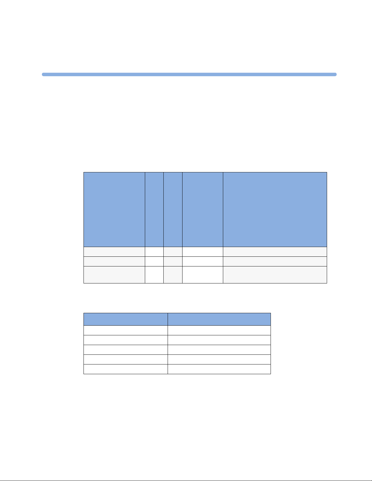
gases.The following table shows the main features and the patient monitor compatibility for the three
gas analyzers:
Automatic
Gas Analyzer
Agent ID
Compatibility
Number of Gases measured
M1013A IntelliVue G1 3 1n/aIntelliVue MP20/30/40/50
M1019A IntelliVue G5 3 22 out of 5IntelliVue MP20/30/40/50/60/70/80/90
M1026B AGM 3 11 out of 5IntelliVue MP40/50/60/70/80/90 and
The gas analyzers measure the Airway Respiration Rate (awRR) and provide end tidal (et) and inspired
(in) values for the following gases:
Respiratory Gases Anesthetic Agents
Carbon dioxide (CO2)Halothane
Nitrous oxide (N
Oxygen (O
The gas analyzers must only be used by qualified personnel.
O) Isoflurane
2
) Enflurane
2
Number of Agents
measured
Sevoflurane
Desflurane
Philips ACMS; Philips V24/26
1
Page 8
1 Using the Gas Analyzer Understanding the Gas Analyzer Display
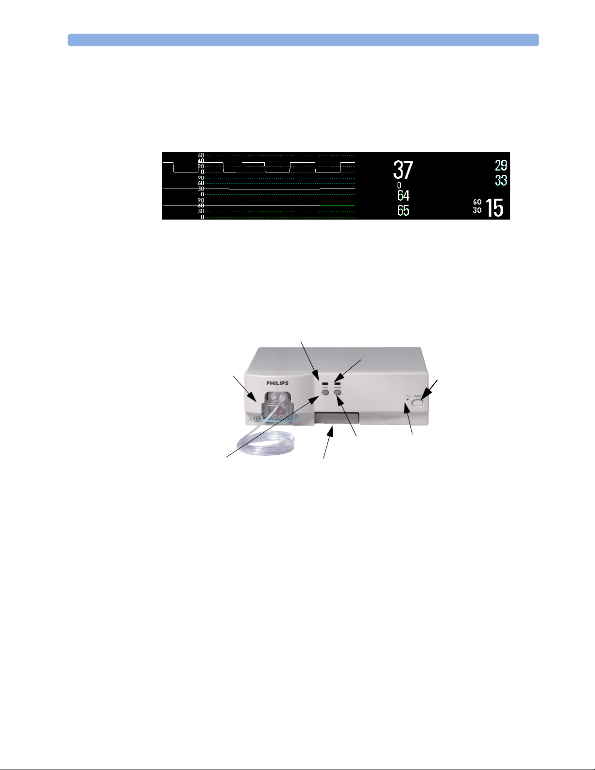
Understanding the Gas Analyzer Display
The gas analyzers can send waves and numerics for all measured gases for display on the monitor
screen. This example shows the CO
configured to look different.
, O2, and N2O waves and numerics. Your display may be
2
CO2
O2
N2O
etCO2
imCO2
etN2O
inN2O
awRR
etO2
inO2
rpm
M1013A IntelliVue G1 & M1019A IntelliVue G5 Major Parts and Keys
Setup LED
Watertrap
Standby LED
Power on/off
Standby Key
Setup Key
The setup LED lights when the Setup Gas Analyzer menu is open, when the module is first
switched on (for 5 - 10 seconds), and if there is a problem with the communication between the gas
analyzer and the monitor. The standby LED lights up when the gas analyzer is in standby.
2
Quick Mount Release
Power LED
Page 9
M1026B Major Parts and Keys 1 Using the Gas Analyzer
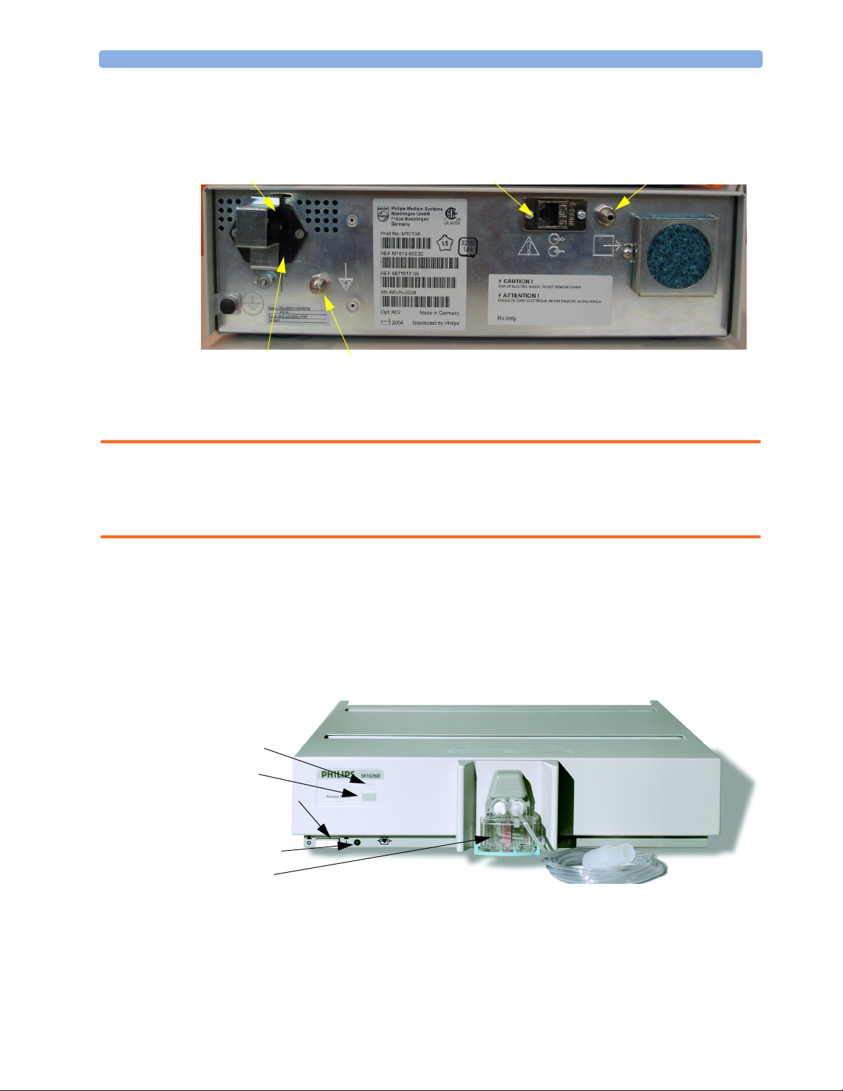
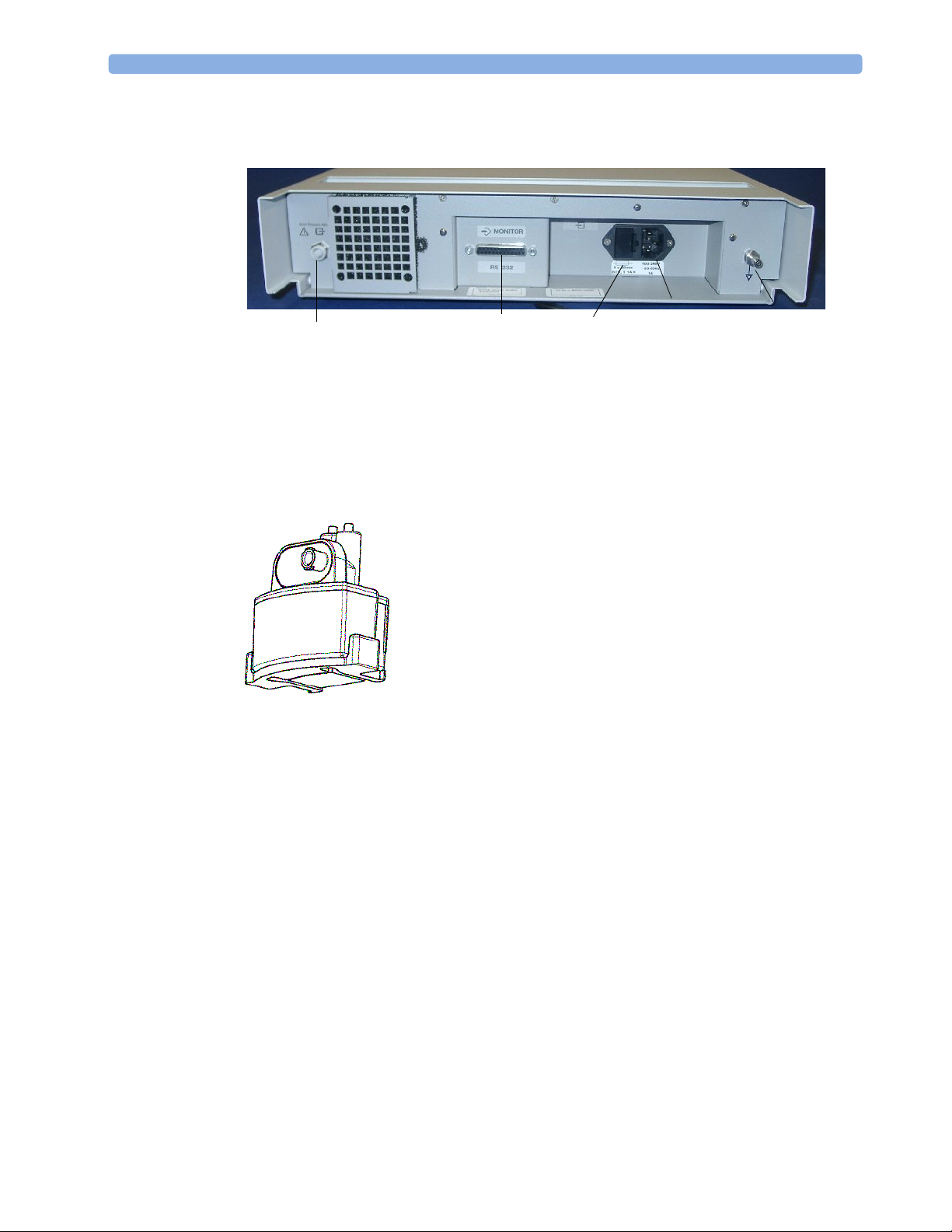
M1013A IntelliVue G1 / M1019A IntelliVue G5 Rear Panel
Power Inlet
Fuses
The RJ-45 connector is the interface connector for the Philips IntelliVue patient monitors.
WARNING • The M1013A IntelliVue G1 may only be used with the Philips IntelliVue MP20/30/40/50 patient
monitors. Connections to other devices may result in a safety hazard.
• The M1019A G5 may only be used with the Philips IntelliVue MP20/30/40/50/60/70/80/90
patient monitors. Connections to other devices may result in a safety hazard.
Equipotential Grounding Terminal
RJ-45
Gas Outlet
Make sure that the anesthetic gas outlet at the rear of the module is connected to the gas scavenging
system or the gas return line.
See your gas analyzer’s service guide for further information on connecting devices.
M1026B Major Parts and Keys
irway Gases LED
irway Gases Key
Power On/
Off switch
Power LED
Wat er tr ap
The setup airway gases LED lights when the Setup Gas Analyzer menu is open, when the module
is first switched on (for 5 - 10 seconds), and if there is a problem with the communication between the
M1026B and the monitor.
3
Page 10
1 Using the Gas Analyzer M1026B Major Parts and Keys
M1026B Rear Panel
Gas Outlet
Make sure all devices connected to the RS232 connectors are isolated. Make sure that the anesthetic
gas outlet at the rear of the module is connected to the gas scavenging system or the gas return line.
See the M1026B Anesthetic Gas Module Service Guide for further information on connecting devices.
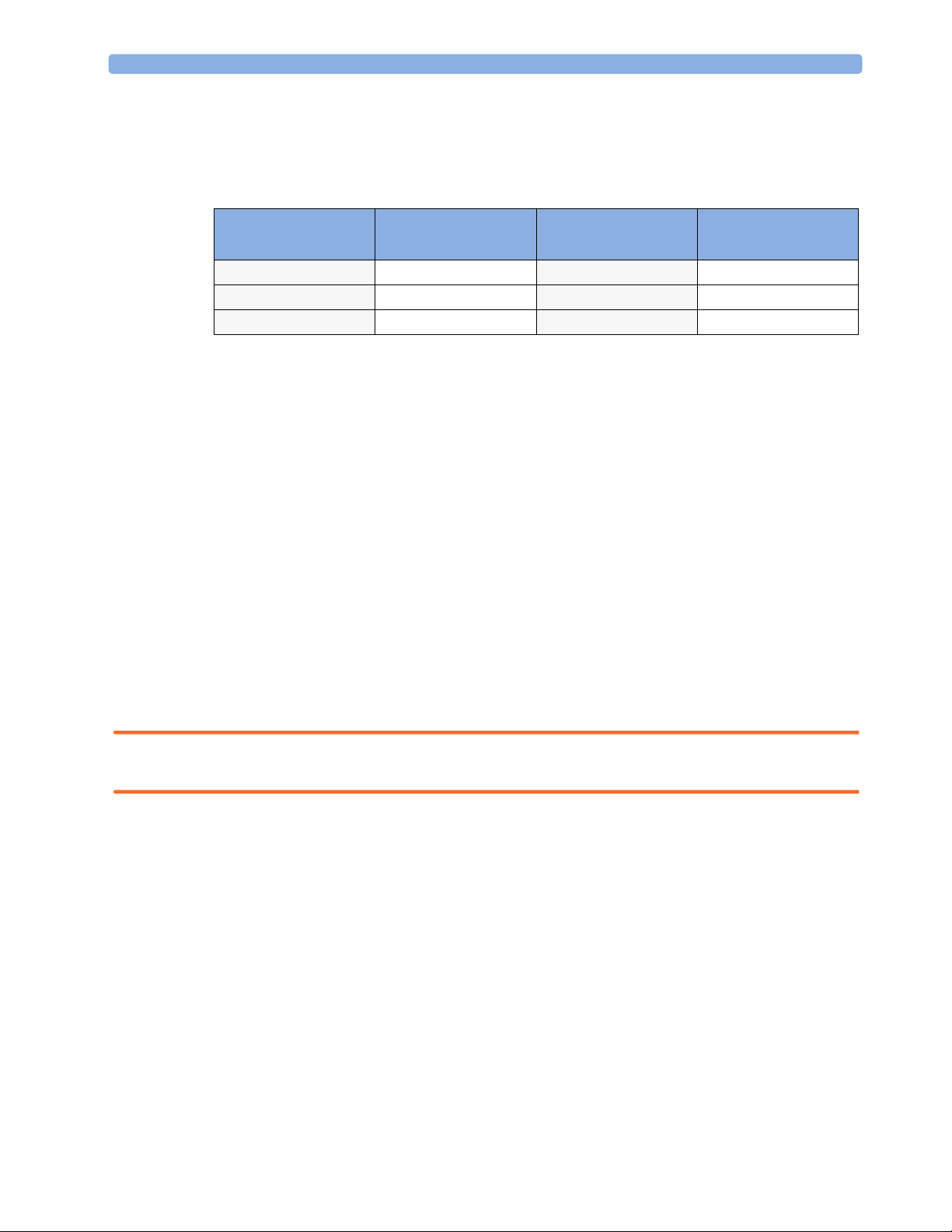
Watertrap M1657B
RS232
Connector
The watertrap prevents water and other fluids from passing into the
gas analyzer and causing contamination and/or internal occlusions. It
has a water reservoir in which fluids are collected, two water
separation filters, and two shut-off fuses as a backup mechanism for
the water separation filters.
The watertrap is for multi-patient use. It must be exchanged at least
every two weeks or when watertrap is full.
Fuses
Power
Inlet
Equipotential
Grounding
4
Page 11

Understanding the Gas Measurement 1 Using the Gas Analyzer
Understanding the Gas Measurement
M1013A IntelliVue G1 & M1019A IntelliVue G5
The M1013A IntelliVue G1 and the M1019A IntelliVue G5 use a technique called Non-Dispersive
Infrared Gas Concentration Measurement (NDIR) to measure the concentration of certain gases.
The gases which can be measured by the M1013A IntelliVue G1 and the M1019A IntelliVue G5
absorb infrared (IR) light. Each gas has its own absorption characteristic. The gas is transported into a
sample cell, and an optical IR filter selects a specific band of IR light to pass through the gas. For
multiple gas measurement, such as in the M1013A IntelliVue G1 or the M1019A IntelliVue G5, there
are multiple IR filters. The higher the concentration of gas in a given volume the more IR light is
absorbed. This means that higher concentrations of IR absorbing gas cause a lower transmission of IR
light. The amount of IR light transmitted after it has been passed through an IR absorbing gas is
measured. From the amount of IR light measured, the concentration of gas present can be calculated.
This calculation provides the gas measurement value. Oxygen is measured by an additional sensor in
the M1013A IntelliVue G1 and the M1019A IntelliVue G5 using its paramagnetic properties. The gas
is transported into a sample cell. The higher the oxygen concentration, the higher the measured effect.
The oxygen concentration can be calculated from the amplitude of the effect.
NOTE The presence of organic cleaning solutions or gases containing freon may impact the accuracy of the
infrared gas measurement.
M1026B AGM
The M1026B Anesthetic Gas Module uses a technique called Dispersive Infrared (DIR) to measure the
concentration of certain gases. The gases measured (except oxygen) by the M1026B Anesthetic Gas
Module absorb infrared (IR) light. Each gas has its own absorption characteristic. The gas is
transported into a sample cell. A diffraction grating is used to scan the relevant wavelength range of the
IR light that passes through the sample cell. The higher the concentration of gas the more IR light is
absorbed, and from the amount of IR light measured, the concentration of gas present can be
calculated.
Individual gases have an individual spectral fingerprint. A mathematical algorithm is used to analyze
the spectrum and to identify the anesthetic agents in the gas. Oxygen is measured by an additional
sensor in the M1026B Anesthetic Gas Module using its paramagnetic properties. The gas is
transported into a sample cell. The higher the oxygen concentration, the higher the measured effect.
The oxygen concentration can be calculated from the amplitude of the effect.
NOTE The presence of organic cleaning solutions or gases containing freon may impact the accuracy of the
infrared gas measurement.
Connecting Gas Analyzer Accessories
The gas analyzer accessories and part numbers are listed in the accessories section.
1 Insert the M1657B watertrap into the watertrap socket by gently pushing
it up and in. Make sure that the watertrap snap lock clicks into place
2 Connect the gas sample tubing to the Luer connector of the watertrap.
5
Page 12

1 Using the Gas Analyzer Connecting Gas Analyzer Accessories
3 Connect the other end of the gas sample tubing to the patient via the airway adapter.
2
3
4
1
5
6
7
1 M1657B Watertrap
2 Watertrap connector prongs
3 Luer connector (gas sample inlet)
4Snap lock
5 M1658A Gas Sample Tubing
6Gas sample port
7Airway Adapter, either
13902A Elbow Airway Adapter
or M1612A Straight Airway Adapter
8 Connects to the patient
9 Connects to the Anesthesia Machine
9
8
WARNING Make sure that you do not accidentally connect the luer connector of the gas sample line to an infusion
link or any other links in the patient vicinity.
6
Page 13

Using the Gas Analyzer Setup Menus 1 Using the Gas Analyzer
CAUTION Airway Adapter: Use a Philips Airway Adapter listed in the Accessories section of this manual and
position it so that the part connecting to the gas sample tube is pointing upwards. This prevents
condensed water from passing into the gas sample tube and causing an occlusion. Philips airway
adapters have a built-in port extending from the adapter wall, which reduces the risk of a blockage
occurring.
Watertrap: To minimize the risk of internal contamination, never leave the gas analyzer running
without a watertrap attached (except during a watertrap exchange).
Gas Sample Tube: Do not use the gas sample tube if it is kinked, as it may cause an occlusion or
leakage.
Room Ventilation Make sure that the room in which the gas analyzer is used is well-ventilated with
fresh air. Gases or fumes that mix with and contaminate the room air may degrade measurement
accuracy. Use either a Gas Exhaust Return Filter/Gas Exhaust return Tubing to return gas samples to
the breathing circuit or connect a scavenging system to the gas exhaust port and remove the gas sample.
Note that Gas Exhaust return tubing may not be available for use in all geographies.
Do not use the gas analyzer in a hyperbaric chamber with oxygen enrichment. Also, the ambient air
must be free of CO
enrichment.
2
WARNING Ensure that the connections are tight. Any leak in the system can result in erroneous readings due to
ambient air mixing with patient gases.
Using the Gas Analyzer Setup Menus
Many gas analyzer settings can be changed just like other measurement settings. These are described in
the chapter on Basic Operation in the Instructions for Use of your patient monitor, only gas analyzerspecific settings are described here.
To change settings for individual gases, enter the setup menu for the individual gas:
♦ select the measurement numeric on the monitor screen, or
♦ select the required gas label in the Setup <Gas Analyzer> menu.
To change Gas Analyzer settings, enter the
♦ select one of the gas analyzer numerics on the monitor screen and then select the menu item
Setup <Gas Analyzer>, or press the Setup hardkey or Airway Gases hardkey on the gas
analyzer.
Choosing Numerics for Display
For each gas the gas analyzer measures, you can choose which numerics are displayed with the
waveform on the screen:
Setup <Gas Analyzer> menu:
et displays the endtidal numerics,
–
in displays the inspiratory numerics,
–
et+in displays both endtidal and inspiratory numerics.
–
Off switches off measurement of that particular gas.
–
7
Page 14

1 Using the Gas Analyzer Using the Gas Analyzer Setup Menus
– MAC displays the minimum alveolar concentration of an anesthetic agent at which patients do not
respond with movement to a painful stimulus.
– MACawk (MAC awake) displays the minimum alveolar concentration of an anesthetic agent at
which patients respond to verbal command.
No waveforms or numerics will be shown for gases set to
To change the displayed numeric, in the
measured to call up a pop-up list of numerics available and then select the numeric you want to display.
As the inspired minimum is measured for CO
Humidity Correction for CO2
The gas analyzer is configured to correct the CO2 measurement for either Body Temperature Pressure
Saturated (BTPS), to account for humidity in the patient’s breath, or Ambient Temperature Pressure
Dry (ATPD).
♦ In the Setup CO2 menu, see the menu item Humidity Corr. to see which correction
applies. It is either
Please refer to the Measurement Specifications in the Installation and Specifications chapter of this
manual for details on the humidity correction.
Wet for BTPS or Dry for ATPD.
Adjusting Wave Scales
1 In the Wave menu or the Setup menu for the gas, select Scale.
2 Choose a suitable scale range from the pop-up list.
Off, and no alarms will be generated.
Setup <Gas Label> menu, select the label of the gas
(imCO2), the numeric label is im instead of in.
2
8
Page 15

Changing the Apnea Alarm Delay 1 Using the Gas Analyzer
Changing the Apnea Alarm Delay
The apnea alarm delay time determines the time limit after which the monitor alarms if the patient
stops breathing.
1 In the Setup CO2 menu, select awRR.
2 In the Setup awRR menu, select Apnea Time.
3 Choose the apnea alarm delay time.
WARNING The safety and effectiveness of the respiration measurement method in the detection of apnea,
particularly the apnea of prematurity and apnea of infancy, has not been established.
Deriving Limit Alarms from awRR
1 In the Setup CO2 menu or in the Setup <Gas Analyzer> menu, select awRR.
2 In the Setup awRR menu, select Alarms.
3 Select On to derive alarms from the airway respiration signal or Off to disable them.
Alarms and Zero Calibration
When a zero calibration is in progress, the physiological alarm detection is suspended. When the
calibration is finished, the gas analyzer resumes alarm detection. If an alarm condition is present after
the zero calibration, the alarm will be activated within the specified alarm delay time.
WARNING If an apnea occurs during a zero calibration, the time delay between the start of apnea and the
activation of the apnea alarm could be up to 24 seconds plus the configured apnea delay time. After
startup or after continuous operation of the M1013A IntelliVue G1 or the M1019A IntelliVue G5 of
4 months or more the time delay could be up to 93 seconds plus the configured apnea time for a single
time.
Automatic Alarm Suppression
Your monitor can be set to suppress alarms until it detects that a patient has been connected to the gas
analyzer (when breathing is detected). This feature is called
or
Off in the monitor’s Configuration Mode.
No Al til Breath and can be set to On
9
Page 16
1 Using the Gas Analyzer Agent Identification
Agent Identification
The following table shows the Agent Identification possibilities of the different gas analyzers:
Gas Analyzer Manual Agent
Identification
M1013A IntelliVue G1 yes no n/a
M1019A IntelliVue G5 no yes 2
M1026B AGM yes yes 1
NOTE Only the M1026B AGM allows switching the agent identification mode between Agent Id:
Manual and Agent Id: Auto. Nevertheless, agent identification behavior for the M1013A
IntelliVue G1 and the M1019A IntelliVue G5 is described below in the Manual Agent ID (M1013A)
and the Automatic Agent ID (M1019A) sections.
Setting the agent identification mode to Agent Id: Manual lets you choose the anesthetic agent
manually. If you choose the setting Agent Id: Auto, the gas analyzer automatically identifies the
predominant anesthetic agent(s) in the breathing circuit.
♦ To change the agent identification mode, in the Setup AGT menu, select Agent Id: to toggle
between the settings
Auto and Manual.
Automatic Agent
Identification
Number of agents
identified
If Agent ID is Set to Manual
To change the agent monitored, when Agent Id is set to Manual:
♦ In the Setup <Agent label> menu, select Agent to call up a pop-up list of available agents
and select the agent you want to monitor. For example, Setup HAL.
M1026B only: If the manually selected agent does not match the agent detected, the INOP CHECK
AGENT appears.
WARNING Make sure to select the correct agent for monitoring. Selecting the wrong agent will cause erroneous
readings.
If Agent ID is Set to Auto (M1019A IntelliVue G5 & M1026B AGM)
As soon as the M1019A IntelliVue G5 or the M1026B AGM has detected the agent(s), a waveform
and numerics for this agent appears on the monitor screen, if they are configured to be displayed.
During the process of identification, the generic label
G5) is shown as a placeholder.
For an anesthetic agent to be detected by automatic agent identification, its concentration must exceed
the identification threshold. The presence of other substances in the patient’s breathing circuit such as
methanol or acetone can influence the agent identification and lead to incorrect values and incorrect
identification.
AGT (AGT1 and AGT2 when using an IntelliVue
10
Page 17

MAC Calculation 1 Using the Gas Analyzer
Exchanging Agents (M1019A IntelliVue G5 & M1026B AGM)
If the anesthetic agent administered to the patient changes, a mixture of both gases is detected by the
M1019A IntelliVue G5 or the M1026B AGM during the transition. The time needed to complete the
exchange depends on the type of anesthesia (low flow or high flow), and the characteristics of the
agents administered (pharmacokinetics). During the exchange, you will see the INOP message
MIXTURE
AGM only: If you are using automatic agent identification, when one of the agents decreases below its
threshold and the other agent predominates, the monitor will recognize the exchange.
M1013A IntelliVue G1 and M1026B AGM only: If you are using manual agent identification, you
must change the agent in the
and (with AGM only) -?- next to the affected numerics.
Agent Setup menu to match the administered agent.
AGT
Agent ID During Emergence from Anesthesia (M1019A IntelliVue G5 & M1026B AGM)
If automatic agent identification is selected during emergence from anesthesia and the agent
concentration falls below the identification threshold, the agent will no longer be identified. The agent
label will remain on the display and the numeric will show
IntelliVue G5) until the monitor detects that a patient is no longer connected. After this, the generic
label
AGT (AGT1 / AGT2 for M1019A IntelliVue G5) will be shown.
0.00 % (numeric unavailable with
♦ To display the correct agent and value, change to manual identification and select the agent
manually.(AGM only)
MAC Calculation
The MAC (Minimum Alveolar Concentration) value of an anesthetic gas or agent denotes the
concentration at which 50% of a population of anesthetized patients do not respond with movement
to a painful stimulus (e.g. a standardized incision through the skin). The MAC awake represents the
concentration at which 50% of a population of anesthetized patients responds to verbal command.
The Philips IntelliVue patient monitors offer three configurable methods of MAC calculation:
•Uncorrected MAC
•Ambient Pressure Corrected MAC
• Enhanced MAC Correction
The preferred method must be set in configuration mode of your patient monitor. The total MAC and
MACawk values can then be selected for display on your monitor. The sections below describe how
these values are calculated with the different methods.
To switch the MAC and/or the MACawk parameter on, set MAC and /or MACawk to ON in the gas
analyzer setup menu.
NOTE • The MACawk value can only be displayed if MAC Correction is configured to “Enhanced”.
• MAC Calculation is only available in IntelliVue patient monitors with software revision C.0 or
higher.
• Ambient Pressure Corrected MAC and Enhanced MAC Correction are not available in the USA.
11
Page 18

1 Using the Gas Analyzer MAC Calculation
Uncorrected MAC
If the MAC Correction is configured to “Off” the uncorrected MAC is calculated. The MAC value is
not corrected for ambient pressure, age, temperature or any other individual factors influencing the
effect of volatile anesthetic agents.
In order to calculate the MAC value the standard 1MAC concentrations of anesthetic agents and
nitrous oxide are required. The following table lists these concentrations (according to the EN ISO
21647:2004 standard). The values are based on the assumptions that the patient is 40 years old (except
for Desflurane where 25 years are assumed), the body temperature is 37° and the atmospheric pressure
is 760 mmHg (1 atm):
Agent Halothane Enflurane Isoflurane Desflurane Sevoflurane N2O
1MAC 0.77 vol% 1.7 vol% 1.15 vol% 7.3 vol% 2.1 vol% 105 vol%
For each volatile anesthetic agent detectable by the gas analyzer the MAC value for the specific agent
(MAC(AA)) is calculated as follows:
etConc(AA)
MAC(AA)
-----------------------------
=
1MAC(AA)
where AA = Anesthetic Agent and etConc = end-tidal concentration
In the same way, the MAC value for nitrous oxide (MAC(N2O) is derived from the measured value of
the nitrous oxide end-tidal concentration (etConc(N2O)):
etCONC(N2O)
MAC(N2O)
Finally, the total MAC value of nitrous oxide and the selected anesthetic agent is calculated as follows:
------------------------------------
=
1MAC(N2O)
MAC MAC(N2O) MAC(AA)+=
NOTE Gas components (N2O and/or anesthetic agent) which are switched off, are not included in the total
MAC computation.
Ambient Pressure Corrected MAC (not available in the USA)
If the MAC Correction is configured to “Amb. Pressure”, the MAC is corrected to reflect the effect of
a different partial pressure at another altitude.
12
Page 19

MAC Calculation 1 Using the Gas Analyzer
)
The total MAC value is calculated in the same way as for the uncorrected MAC and then corrected for
ambient pressure according to the following equation:
Pamb
MAC uncorrected total MAC
-------------------------- -
×=
760 mmHg
Enhanced MAC Correction (not available in the USA)
If the MAC Correction is configured to “Enhanced”, the MAC value is corrected for age, temperature
and ambient pressure.
The basic 1MAC values used for enhanced MAC Correction are listed in the table below.These values
are taken from the scientific article Age, minimum alveolar anaesthetic concentration and minimum
alveolar anaesthetic concentration-awake by Edmond I Eger II (Anesth Analg 2001, 93: 947-53)and
differ slightly from the standard 1MAC values used for the uncorrected MAC.
NOTE There is no correction data available for Enflurane, so the standard 1MAC value is used in this case.
For standard conditions as assumed for the uncorrected MAC the values are:
Agent Halothane Enflurane Isoflurane Desflurane Sevoflurane N2O
1MAC 0.757 vol% no correction 1.19 vol% 6.45 vol% 1.8 vol% 114 vol%
The patient age can either be entered into the IntelliVue patient monitor, or provided by the
information system if the monitor is networked. The patient temperature is obtained from a
temperature measurement by the monitor. Only the following temperature labels are accepted for
correction (listed in order of priority):
–Tcore
–Tblood
Patient Age Range: 1 to 100 years
Temperature Range: 25 to 45°C
Any age or temperature value outside the supported ranges is rounded to the according lower or upper
boundary.
If the patient age is not available, the MAC correction will assume a default age of 40 years. If none of
the listed temperatures is measured, a default temperature of 37°C is taken for MAC Calculation. In all
of these cases the INOP “MAC CORRECTION?” is issued and the MAC numerics are marked
questionable.
The 1MAC value for a specific potent inhaled anesthetic agent at age 40 (see table above) is corrected
for patient age and temperature effects as follows (T given in degree Celsius and the age given in years):
1MACcorr(AA) (1 ((0.05)–(37T)))–× 1MAC(AA) 1.32 10
×××=
-(0.00303 Age
×
13
Page 20

1 Using the Gas Analyzer MAC Calculation
With the 1MAC value corrected for age and temperature at a standard pressure of 760mmHg, the
MAC value of an anesthetic agent can be calculated as follows:
etConc(AA)
MAC(AA)
MAC(ENF)
The MAC value of nitrous oxide is obtained from the 1MAC concentration of nitrous oxide at age 40
corrected for the patient’s age only (no correction is made for temperature):
MAC(N2O)
----------------------------------------------------------------------------------------------- -
=
1MAC(N2O) 1.378 10×
The total MAC value for the combination of nitrous oxide plus the selected agent is obtained by
adding the MAC value for the agent and the MAC value for nitrous oxide and correcting this sum for
ambient pressure:
-------------------------------------- -
=
1MACcorr(AA)
etConc(ENF)
------------------------------- -
=
1MAC(ENF)
etConc(N2O)
×
(for all agents except Enflurane)
(for Enflurane)
-(0.00347 Age)×
Pamb
MAC MAC(N2O) MAC(AA) or MAC(ENF)+[]
NOTE Gas measurements which are switched off, are not included in the total MAC computation. The
calculated MAC values for a 40 year old patient at a temperature of 37°C are similar but not identical
to the 1MAC values given in the table for uncorrected MAC configuration.
In addition, the MAC
values can be determined as follows:
awake
MACawk(AA)
=
MACawk(HAL)
MAC(AA)
------------------------- -
0.343
MAC(HAL)
----------------------------- -
=
0.551
(for all agents except Halothane)
-------------------------- -
×=
760 mmHg
(for Halothane)
14
Page 21

Removing Gas from the Circuit 1 Using the Gas Analyzer
MAC(N2O)
MACawk(N2O)
The total MACawk value is obtained by adding the indivdual MACawk values up:
---------------------------- -
=
0.551
(for nitrous oxide)
MACawk MACawk(N2O) MACawk(AA) or MACawk(HAL)+=
Removing Gas from the Circuit
If inhalation anesthetics are used during anesthesia, pollution of the operating room should be
prevented by either returning the filtered gas sample to the breathing circuit (may not be available in all
geographies) or by disposing of the gas sample.
Your hospital policy may not permit the use of gas return systems.
WARNING Make sure that you do not accidentally connect the luer connector of the gas sample line to an infusion
link or any other links in the patient vicinity.
Returning the Gas Sample
NOTE Gas Sample Return may not be available in all geographies.
Use an M1656B Gas Exhaust Return Filter and M1655B Exhaust Return Tubing as instructed in the
documentation supplied with the filter or the gas exhaust return line to return the gas sample to the
patient’s breathing circuit. Make sure the sample gas is routed through the CO
back to the patient.
absorber before going
2
Removing the Gas Sample
To remove the gas sample from the breathing circuit, a scavenging system must be connected to the gas
exhaust port. Use either:
• a gas exhaust scavenging tube
• a ventilator reservoir, where the suction pressure does not exceed 0.3-0.4mm Hg
• a scavenging interface.
CAUTION Make sure to compensate for any possible reduction of tidal volume caused by gas sampling.
15
Page 22

1 Using the Gas Analyzer Entering Gas Analyzer Standby Mode
Entering Gas Analyzer Standby Mode
During standby, the gas analyzer’s gas sample intake pump and other internal components are
automatically switched off to increase the lifetime of the device. The message
STANDBY
M1026B AGM to warm up to resume monitoring. The M1013A IntelliVue G1 and the M1019A
IntelliVue G5 require up to 30 seconds warm up time before you can resume monitoring.
The gas analyzer standby mode is linked to the monitor standby mode:
• If the monitor enters standby mode, the gas analyzer also enters standby mode.
• If the monitor leaves standby mode, the gas analyzer automatically also leaves standby mode.
• If the gas analyzer enters or leaves standby mode, this does not affect the monitor.
• If the gas analyzer is disconnected from the monitor, it enters standby mode automatically after 3 to
5 minutes (M1013A IntelliVue G1 and M1019A IntelliVue G5 only).
The gas analyzer enters standby mode automatically when no breath is detected for a configured period
of time (for M1026B AGM: if CO
goes below adaptive threshold).
is shown on the monitor. When you exit standby, you do not need to wait for the
is less than 4 mmHg, for M1013A G1 and M1019A G5: if CO2
2
<GAS ANALYZER>
16
Page 23

Zero Calibration 1 Using the Gas Analyzer
To enter or leave standby mode manually:
•in the
Setup <Gas Analyzer> menu, select Set to Standby or Exit Standby or press the
IntelliVue G1 or IntelliVue G5 Standby hardkey
Zero Calibration
The gas analyzer zero calibration maintains the accuracy of the gas measurements by sampling and
analyzing room air. It takes about 15 to 21 seconds (M1013A G1 and M1019A G5) / 10 to 20 seconds
(M1026B) to complete and may not be interrupted. If a zero calibration fails, a second zero calibration
is performed automatically. The M1013A G1 and the M1019A G5 also attempt a third zero
calibration if the second one fails. During the zero calibration, the waveform is flat and numerics are
not updated. In case of apnea the numerics (except awRR) are marked invalid on the M1013A G1 and
the M1019A G5, and in case of a zero retry they are marked not available on all gas analyzers.
NOTE After startup or continuous operation for 4 months of the M1013A IntelliVue G1 and the M1019A
IntelliVue G5 the zero calibration can take up to 93 seconds. If necessary, the zero calibration can be
suspended for 5 minutes.
Automatic Zero Calibration
M1013A IntelliVue G1 and M1019A IntelliVue G5
A zero calibration is carried out automatically during warmup. After monitoring has been started zero
calibrations are not performed more than every 2 hours. If the M1013A G1 or the M1019A G5 was in
standby when one of the above triggers for zero calibration occurred, the zero calibration is carried out
when the gas analyzer leaves standby. Typical zero time is 21 seconds. A longer zero calibration may
occur if the M1013A G1 or the M1019A G5 is not switched off (i.e. running or in standby) for a
longer period of time.
M1026B AGM
A zero calibration is carried out automatically after the module has been switched on, and then once
every hour after monitoring has been started. If the M1026B was in standby when one of the above
triggers for zero calibration occurred, the zero calibration is carried out when the M1026B leaves
standby. Maximum zero time is 20 seconds.
Carrying Out Manual Zero Calibration
♦ To manually start a zero calibration, in the Setup <Gas Analyzer> menu, select Zero Cal,
then select the
Confirm pop-up key.
Suppressing Zero Calibration
To temporarily prevent an automatic zero calibration from being started,
♦ in the Setup <Gas Analyzer> menu, select No Zero for 5min.
Selecting
This is not possible if a zero calibration is pending (automatic zero requested).
No Zero for 5min again before the timer has timed out resets the timer to five minutes.
17
Page 24

1 Using the Gas Analyzer Using the Gas Analyzer During a Cardiopulmonary Bypass
Using the Gas Analyzer During a Cardiopulmonary Bypass
CAUTION During a cardiopulmonary bypass, the anesthesiologist may cease periodic mechanical ventilation. In
these cases, it is important to note that an active gas analyzer will continue to suck gases from the
patient-ventilator circuit during that time. This will cause the airway pressure to drop if no active
measures are taken to keep the patient-ventilator circuit stable.
To stop the gas analyzer from sucking gases out of the circuit, either:
• activate the gas analyzer standby mode or
disconnect the sample line from the gas analyzer or from the patient-ventilator circuit.
Safety Information
To avoid condensed water collecting in the gas sample tube, position the gas analyzer at or above the
patient level. Do not set up the gas analyzer in a position where liquid could spill onto it.
WARNING Detecting leaks: Any leak in the tubing and connections from the patient to the gas analyzer may
result in dilution of the gas mixture with ambient air. If this leak exceeds a certain magnitude, the value
of gases and anesthetic agents displayed on the monitor may differ significantly from the actual
concentration in the patient’s breathing circuit. Erroneous values may lead to inappropriate
intervention and patient safety may be at risk.
Unexpected values: If an unexpected gas concentration value appears on the monitor, or if the waves
appear to be flatter than normal, visually inspect the entire tubing and replace if necessary. If no
occlusion or leakage can be found, replace the watertrap with a new one and check the values.
CAUTION Gas Analyzer ports: Do not apply excessive pressure to the gas analyzer’s inlet or outlet ports, for
example from a syringe, as this may cause damage to the pneumatic and optical systems.
Cleaning: Switch off the gas analyzer during cleaning, as an intake of cleaning fluids or fumes may
damage the device.
M1013A IntelliVue G1 and M1019A IntelliVue G5: Since the M1013A IntelliVue G1 and the
M1019A IntelliVue G5 contain no internal bacterial filters never switch them on without a watertrap
installed. Operating these gas analyzers without a watertrap may result in damage to the instrument.
18
Page 25

Safety Information 1 Using the Gas Analyzer
WARNING • Possible Explosion Hazard if used in the presence of flammable anesthetics.
• Do not use antistatic or conductive breathing tubes as they may cause burns in case of
electrosurgery.
• Do not open the gas analyzer. Contact with exposed electrical components may cause electrical
shock.
• Make sure that you do not accidentally connect the luer connector of the gas sample line to an
infusion link or any other links in the patient vicinity.
19
Page 26

1 Using the Gas Analyzer Safety Information
20
Page 27

10Maintenance and
Troubleshooting
WARNING Schedule: Failure on the part of the responsible individual hospital or institution employing the use of
this equipment to implement a satisfactory maintenance schedule may cause undue equipment failure
and possible health hazards.
Contact: If you discover a problem with any of the equipment, contact your service personnel, Philips,
or your authorized supplier.
Inspecting the Equipment and Accessories
2
You should perform a visual inspection before every use, and in accordance with your hospital’s policy.
With the gas anaylzer switched off:
1 Examine unit exteriors for cleanliness and general physical condition. Make sure that the housings
are not cracked or broken, that everything is present, that there are no spilled liquids and that there
are no signs of abuse.
2 Inspect all accessories (cables, transducers, sensors and so forth). If any show signs of damage, do
not use.
Inspecting the Cables and Cords
Examine all system cables, the power plug and cord for damage. Make sure that the prongs of the plug
do not move in the casing. If damaged, replace it with an appropriate Philips power cord.
Maintenance Task and Test Schedule
The following tasks are for Philips-qualified service professionals only. All maintenance tasks and
performance tests are documented in detail in the Service Guide for your gas analyzer.
Ensure that these tasks are carried out as indicated by the gas analyzer’s maintenance schedule, or as
specified by local laws. Contact a Philips-qualified service provider if your gas analyzer needs a safety or
performance test. Clean and disinfect equipment to decontaminate it before testing or maintaining it.
21
Page 28

2 Maintenance and Troubleshooting Maintenance Task and Test Schedule
Maintenance and Test Schedule Frequency
Safety checks according to IEC 60601-1 At least once every two years, or as needed, after any repairs
where the power supply is replaced, or if the gas analyzer has
been dropped.
M1013A IntelliVue G1 and M1019A
IntelliVue G5 preventive maintenance
and safety and performance assurance
(SPA)
M1026B AGM preventive maintenance At least once every two years or if you suspect the measurement
M1026B Safety and Performance
Assurance (SPA)
M1013A IntelliVue G1, M1019A
IntelliVue G5 and M1026B AGM
ventilator fan
At least once a year or if you suspect the measurement values are
incorrect.
values are incorrect.
At least once a year or if you suspect the measurement values are
incorrect.
Check at least every six months.
22
Page 29

Troubleshooting 2 Maintenance and Troubleshooting
Troubleshooting
If you suspect a problem with the gas measurement, read the Using the Gas Analyzer chapter and
doublecheck that you have set up the measurement correctly.
If you suspect an intermittent, system-wide problem call your service personnel.
Disposing of the Gas Analyzer
WARNING To avoid contaminating or infecting personnel, the environment or other equipment, make sure you
disinfect and decontaminate the gas analyzer appropriately before disposing of it in accordance with
your country’s laws for equipment containing electrical and electronic parts. For disposal of parts and
accessories, where not otherwise specified, follow local regulations regarding disposal of hospital waste.
You can disassemble the gas analyzer as described in the Service Guide for your gas analyzer.
– The top cover uses only one kind of steel.
– You can recycle the paper Instructions for Use.
– Dispose of accumulated fluids in the watertrap according to your local regulations and hospital
policy.
Disposing of Empty Calibration Gas Cylinders
1 Empty the cylinder completely by pushing in the pin of the regulator valve or by pulling out the
pin of the fill wave using a tire valve stem wrench or a pair of needle nose pliers.
2 When the cylinder is empty, either remove the valve stem from the fill (or regulator) hole, or drill a
hole in the cylinder.
3 Write “Empty” on the cylinder and dispose of it appropriately for scrap metal.
WARNING Ensure that the cylinder is completely empty before trying to remove the valve stem or drill the tank.
23
Page 30

2 Maintenance and Troubleshooting Disposing of Empty Calibration Gas Cylinders
24
Page 31

11Installation and Specifications
The specifications in this section apply to the M1013A IntelliVue G1, the M1019A IntelliVue G5 and
the M1026B Anesthetic Gas Module (AGM).
The M1013A IntelliVue G1 and the M1019A IntelliVue G5 must be installed by qualified personnel.
The M1026B AGM is not user installable and must be installed by qualified service personnel only.
Intended Use
The M1013A IntelliVue G1 and the M1019A IntelliVue G5 provide a non-dispersive infrared
measurement of respiratory and anesthetic gases and a paramagnetic measurement of oxygen (Fast O
The M1026B Anesthetic Gas Module provides a dispersive infrared measurement of respiratory and
anesthetic gases and a paramagnetic measurement of oxygen (Fast O
The M1013A IntelliVue G1 is designed to work with the Philips IntelliVue MP20/30/40/50 monitors,
the M1019A IntelliVue G5 and the M1026B is designed to work with the Philips IntelliVue MP20/
30/40/50/60/70/80/90 monitors. In addition the M1026B Anesthetic Gas Module is designed to work
with the Philips ACMS and V24/V26 patient monitors. All gas analyzers are intended for measuring
the airway gases of ventilated patients in health care facilities.
3
).
2
).
2
The M1013A IntelliVue G1, the M1019A IntelliVue G5 and the M1026B AGM are not therapeutic
devices.
CAUTION U.S. Federal Law restricts this device to sale by or on the order of a physician.
Use only hospital grade power lines.
Do not store or operate the gas analyzer outside the storage and operating conditions specified in this
chapter.
Do not expose the gas analyzer to excessive heat or sunlight as this could lead to overheating of the
instrument and result in injuries.
Avoid any restriction or blockage of air flow as this could cause overheating of the gas analyzer and
result in injuries.
Follow the mounting and installation instructions in your service guide closely to avoid injuries caused
by the gas analyzer or of the device mounted on top of it falling down.
Mechanical vibrations or shock may have adverse effects on gas measurement values.
25
Page 32

3 Installation and Specifications Manufacturer’s Information
Manufacturer’s Information
You can write to Philips at this address
Philips Medizin Systeme Boeblingen GmbH
Hewlett-Packard Str. 2
71034 Boeblingen
Germany
Visit our website at: www.philips.com.
© Copyright 2002 - 2005. Koninklijke Philips Electronics N.V. All Rights Reserved.
Responsibility of the Manufacturer
Philips considers itself responsible for any effects on safety, reliability and performance of the
equipment only if:
• assembly operations, extensions, re-adjustments, modifications or repairs are carried out by persons
authorized by Philips.
• the electrical installation of the relevant room complies with national standards.
• the instrument is used in accordance with the instructions for use.
To ensure safety, use only those parts and accessories specified for use with the M1013A IntelliVue G1,
the M1019A IntelliVue G5 and the M1026B AGM. If other parts are used, Philips is not liable for any
damage that these parts may cause to the equipment.
See your sales contract for product warranty information.
26
Page 33

Symbols 3 Installation and Specifications
Symbols
These symbols appear on the gas analyzers:
Symbols
Setup*
Refer to accompanying
documents
Standby*
Power On/Off*
Alternating current Electrical input
Applied part has
special protection
against electric
shocks (Type BF
according to IEC
60601-1)and is
defibrillator proof
Protective earth RS232 connector Applied part has
The device
0366
complies with the
requirements of the Council
Directive 93/42/EEC of 14 June
1993 (Medical Device
Directive).
RS-232
Equipotential
grounding
indicator
Gas output indicator Gas input indicator
200206
Electrical output
indicator
Identifies year
and month of
manufacture
special protection
against electric
shocks (Type CF
according to IEC
60601-1) and is
defibrillator proof
* These symbols are replaced by English text in the U.S.A.
27
Page 34

3 Installation and Specifications Installation Safety Information
Installation Safety Information
WARNING • The M1013A IntelliVue G1 may only be used with the Philips IntelliVue MP20/30/40/50 patient
monitors. Connections to other devices may result in a safety hazard.
• The M1019A IntelliVue G5 may only be used with the Philips IntelliVue MP20/30/40/50/60/70/
80/90 patient monitors. Connections to other devices may result in a safety hazard.
• If multiple instruments are connected to multiple socket outlets, the sum of the enclosure leakage
currents must not exceed the limits given in IEC/EN60601-1 and IEC 60601-1-1 respectively.
Consult your service personnel.
NOTE The party assembling or modifying medical electrical units to install a medical electrical system or
assembling or modifying electrical systems according to standard EN/IEC 60601-1-1 (safety
requirements for medical electrical systems) is responsible for the compliance of all requirements of the
standard.
Grounding The M1013A IntelliVue G1, the M1019A IntelliVue G5 and the M1026B AGM must be
grounded during operation. If a three-wire receptacle is not available, consult the hospital
electrician. Never use a three-wire to two-wire adapter.
Equipotential
Grounding
Combining equipment Combinations of medical equipment with non-medical equipment must comply with
Fusing The monitor uses double pole/neutral fusing.
If the M1013A IntelliVue G1, the M1019A IntelliVue G5 or the M1026B AGM is used
in internal examinations on the heart or brain, ensure that the room incorporates an
equipotential grounding system to which the monitor and M1013A IntelliVue G1,
M1019A IntelliVue G5 or M1026B AGM have separate connections.
IEC 60601-1-1. Never use a multiple portable socket-outlet or extension cord when
combining equipment unless the socket outlet is supplied specifically for use with that
equipment.
Installation Instructions
Please refer to the your gas analyzer’s service guide for detailed installation instructions.
Altitude and Barometric Pressure
Altitude and barometric pressure affect gas measurements. The host monitor must be configured at
installation to the correct altitude and the correct barometric pressure values for your hospital site. The
gas analyzers measure barometric pressure with each zero calibration. If the barometric pressure
measured by the gas analyzer differs by more than 60 mmHg from the monitor settings the INOP
Zero Failed is issued to indicate that either the altitude setting is incorrect or the pressure sensor is
defective. In the latter case, the conversions from concentration (vol%) to partial pressure (mmHg,
kPa) may be erroneous.
28
Page 35

M1013A IntelliVue G1 & M1019A IntelliVue G5 Specifications 3 Installation and Specifications
M1013A IntelliVue G1 & M1019A IntelliVue G5 Specifications
Safety Specifications
The M1013A IntelliVue G1 and the M1019A IntelliVue G5 comply with:
IEC 60601-1:1988 + A1:1991 + A2:1995; EN60601-1:1990 + A1:1993 + A2:1995; UL 606011:2003; CAN/CSA C22.2#601.1-M90; IEC 60601-1-2:2001; EN 60601-1-2:2001.
Classification (according to IEC 60601-1): Class 1, Type BF, Continuous Operation.
This ISM device complies with Canadian ICES-001. Cet appareil est conforme a la norme NMB-001
du Canada.
The possibility of hazards arising from software errors was minimized in compliance with
ISO14971:2000, EN60601-1-4:1996 + A1:1999 and IEC 60601-1-4:1996 + A1:1999
Physical and Electrical Specifications
Gas
Analyzer
M1013A
IntelliVue G1
M1019A
IntelliVue G5
Power Consumption: peak: 45W, typical: 25W
Power Range 100 - 240 VAC
Sound Pressure: < 60 dB
If the M1013A IntelliVue G1 or the M1019A Intellivue G5 and its host monitor are without power
for less than one minute, monitoring will resume with all active settings unchanged. If they are without
power for more than one minute, the behavior depends on your configuration. If Automat.
Default is set to Yes, the default profile will be loaded when power is restored. If Automat.
Default is set to No, all active settings are retained, if power is restored within 48 hours. The
Automat. Default setting is made in Configuration Mode of the patient monitor.
Weig ht Size (H x W x D )
< 4,5 kg
< 9,92 lb
< 4,5 kg
< 9,92 lb
90 x 300 x 232 mm
3.54 x 11.81 x 9.13 in
90 x 300 x 232 mm
3.54 x 11.81 x 9.13 in
Environmental Specifications
The M1013A IntelliVue G1 and the M1019A IntelliVue G5 may not meet the performance
specifications given here if stored or used outside the specified temperature and humidity ranges.
When the M1013A IntelliVue G1, the M1019A IntelliVue G5 and related products have differing
environmental specifications, the effective range for the combined products is that range which is
common to the specifications for all products.
29
Page 36

3 Installation and Specifications M1013A IntelliVue G1 & M1019A IntelliVue G5 Specifications
Item Condition Range
Temperature Range Operating 10 to 40 oC (50 to 104 °F)
Non-operating
Humidity Range Operating 5 to 90% Relative Humidity (RH) max. @ 40 °C (104 °F)
Non-operating
Altitude Range Operating -305 m to 2900 m (-1000 to 9515 ft)
Non-operating
Atmospheric Pressure
Range
Warmup Ti m e After switching on: 1 - 2 minutes to measure, 6 minutes for full
Operating 70 kPa to 106 kPa
Non-operating
-20 to 65 oC (-4 to 149 °F)
(non-condensing)
5 to 95% Relative Humidity (RH) max. @ 65 °C (150 °F)
-305 m to 5000 m (-1000 to 16404 ft)
50kPa to 106 kPa
accuracy
Measurement Specifications
Parameter Item Specification
CO
2
O
2
N2O Range 0 to 100 vol%
Halothane
Enflurane
Isoflurane
Sevoflurane
Desflurane
awRR Range 0 to 60 rpm
Range 0 to 76 mmHg
Accuracy
Resolution
Rise Time
Range 5 to 100 vol%
Accuracy
Resolution
Rise Time
Accuracy
Resolution
Rise Time
Range
Accuracy
Resolution
Rise Time
Accuracy
Resolution
Detection Criteria
+0.5 vol% or 12% relative, whichever is greater
1 mmHg
350 msec typical
+ 3 vol%
1 vol%
500 msec typical
2.0 vol% + 8% relative
1 vol%
500 msec typical
Halothane: 0 - 8.5 vol%
Enflurane: 0 - 10.0 vol%
Isoflurane: 0 - 8.5 vol%
Sevoflurane: 0 - 10.0 vol%
Desflurane: 0 - 20.0 vol%
0.15 vol% + 15.0% relative
0.05
500 ms typical
+ 1 rpm
1 rpm
adaptive threshold.
30
Accuracy specifications refer to BTPS for mmHg kPa and STPD for vol% at 40 - 60% relative
humidity. All Performance and accuracy specifications are valid based on gas sample tubing M1658A,
including watertrap M1657B, and airway adapter 13902A.
Page 37

M1013A IntelliVue G1 & M1019A IntelliVue G5 Specifications 3 Installation and Specifications
Humidity Correction: For CO2 the humidity correction can be set to “wet” or “dry”.
Wet: p [mmHg] = c [Vol%] * (p_abs - p_H
O)/100
2
Dry: p [mmHg] = c [Vol%] * p_abs /100
Where p = partial pressure, c = gas concentration, p_abs = pressure in breathing circuit, p_H
mmHg, partial pressure of water vapor of exhaled gas (37
°
C, 100% rh).
O = 47
2
For all other gases the readings are always given as dry values.
Sample Flow Rate: 200ml/min
±20 ml/min
Sample Delay Time: All measurements and alarms are subject to a delay of 5 seconds.
Total System Response Time = 5 + 0.5 seconds (sum of the delay time and rise time).
Leakage < 5ml/min
Air Ingression < 50ml per zero
The drift of measurement accuracy is automatically compensated by the auto zero calibrations.
IntelliVue G1/G5
Alarm
Specifications
etCO2 High 20 to 76 mmHg (2.7 to 10.1 kPa) 19 seconds if no automatic zero calibration
etCO2 Low 10 to 75 mmHg (1.3 to 10.0 kPa)
imCO2 High 0 to 20 mmHg (0 to 2.7 kPa)
inO2 High 19 to 100 vol%
inO2 Low 18 to 99%
inN2O 0 to 82 vol%
in/et
HAL/ISO/ENF
High
in/et
HAL/ISO/ENF
Low
in/et SEV High 0.1 to 9.0 vol%
in/et SEV Low 0.0 to 8.9 vol%
in/et DES High 0.2 to 20.0vol%
in/et DES Low 0.0 to 19.8 vol%
awRR High Neonatal: 30 to 60 rpm
awRR Low 0 to 55 rpm settings < 20 rpm: less than 9seconds
Apnea delay 10 to 40 seconds within 2 sec after alarm criterion (no detected
High Limit Range Delay
occurs within that time.
0.1 to 7.5 vol%
0.0 to 7.4 vol%
Adult & Pediatric: 10 to 60 rpm
> 20 rpm: less than 19 seconds
breath within the adjusted delay time) is met, if
no automatic zero calibration occurs.
31
Page 38

3 Installation and Specifications M1013A IntelliVue G1 & M1019A IntelliVue G5 Specifications
IntelliVue G1/G5
Alarm
Specifications
IntelliVue G5 only:
Agent ID Response Time 14 s for first agent, 19 s for second agent
First Agent
Detection /
Identification
Threshold
Second Agent
Detection /
Identification
Threshold
High Limit Range Delay
All agents max. 0.3 vol%
All agents max. 0.4 vol% of a second agent, except if a
second agent is added to Desflurane, this causes
a mixture identification at the latest if the
concentration of the second agent exceeds 10
vol% of the current Desflurane concentration.
Interfering Gases and Vapours
At the gas levels listed below there is no influence on the specified accuracy of the M1013A IntelliVue
G1 and the M1019A IntelliVue G5.
Gas or Vapour Gas Level in % volume fraction
Nitrous Oxide 60
Halothane 4
Enflurane 5
Isoflurane 5
Sevoflurane 5
Xenon Not for use with Xenon
Helium 50
Metered dose inhaler propellants Not for use with metered dose
inhaler propellants
Desflurane 15
Ethanol 0.3
Isopropanol 0.3
Acetone 0.1
Methane 3
32
Page 39

M1026B Specifications 3 Installation and Specifications
M1026B Specifications
Safety Specifications
The M1026B complies with:
IEC 60601-1:1988 + A1:1991 + A2:1995; EN60601-1:1990 + A1:1993 + A2:1995; UL 606011:2003; CAN/CSA C22.2#601.1-M90; IEC 60601-1-2:2001; EN 60601-1-2:2001.
Classification (according to IEC 60601-1): Class 1, Type CF, Continuous Operation.
This ISM device complies with Canadian ICES-001. Cet appareil est conforme a la norme NMB-001
du Canada.
Physical and Electrical Specifications
Gas
Analyzer
M1026B
AGM
Power Consumption: peak: 35W, typical: 25W
Power Range: 100 - 240 VAC
If the M1026B AGM and its host monitor are without power for less than one minute, monitoring
will resume with all active settings unchanged. If they are without power for more than one minute, the
behavior depends on your configuration. If Automat. Default is set to Yes, the default profile
will be loaded when power is restored. If Automat. Default is set to No, all active settings are
retained, if power is restored within 48 hours. The Automat. Default setting is made in
Configuration Mode of the patient monitor.
Weig ht Size (H x W x D )
6.3 kg
13.9 lb
90 x 370 x 467 mm
3.54 x 14.5 x 18.4 in
33
Page 40

3 Installation and Specifications M1026B Specifications
Environmental Specifications
The M1026B AGM may not meet the performance specifications given here if stored or used outside
the specified temperature and humidity ranges.
When the gas analyzers and related products have differing environmental specifications, the effective
range for the combined products is that range which is common to the specifications for all products.
Gas Analyzer Item Condition Range
M1026B AGM Temperature Range Operating 15 to 40 °C (59 to 104 °F)
Non-operating -20 to 65 °C (-4 to 149 °F)
Humidity Range
Altitude Range
Atmospheric Pressure
Range
Warmup Ti m e
Operating Up to 95% Relative Humidity (RH) max. @ 40 °C (104 °F)
(non-condensing)
Non-operating Up to 95% Relative Humidity (RH) max. @ 65 °C (150 °F)
Operating -305 m to 3048 m (-1000 to 10 000 ft)
Non-operating -305 m to 5486 m (-1000 to 18 000ft)
Operating 70 to 106 kPa
Non-operating 50 to 106 kPa
Full accuracy after selftest is finished (max. 2 min.)
34
Page 41

Measurement Specifications 3 Installation and Specifications
Measurement Specifications
Parameter Item Specification
CO
2
O
2
N2O Range 0 to 85 vol%
Halothane
Enflurane
Isoflurane
Sevoflurane Range 0 - 9.0
Desflurane Range 0 - 20.0
awRR Range 0 to 60 rpm
Agent ID Response Time 15 s typical
Agent Thresholds
for the primary halogenated
anesthetic agent
1. During warmup, the thresholds are three times the values listed.
1
Range 0 to 76 mmHg
Accuracy
Resolution
Rise Time
Range 0 to 100 vol%
Accuracy
Resolution
Rise Time
Accuracy
Resolution
Rise Time
Range
Accuracy
Resolution
Rise Time
Accuracy
Resolution
Rise Time
Accuracy
Resolution
Rise Time
Accuracy
Resolution
Detection Criteria
HAL, ISO, ENF
SEV
DES
+ 1.5 mmHg (0 - 30 mmHg)
5 vol % (30 - 76 mmHg)
+
1 mmHg
410 msec typical
+ 3 vol%
1 vol%
640 ms typical
+1.5 vol% + 5% relative
1 vol%
510 msec typical
0 - 7.5 vol%
+ (0.1 vol% + 4.0% relative)
0.05
Halothane: <900 ms typical
Enflurane < 620 ms typical
Isoflurane < 610 ms typical
+ (0.1 vol% + 4.0% relative)
0.05
< 570 ms typical
+ (0.1 vol% + 4.0% relative)
0.05
< 540 ms typical
+ 2 rpm
1 rpm
6 mmHg variation in CO2.
0.20 vol%
0.24 vol%
0.30 vol%
All Performance and accuracy specifications are valid based on gas sample tubing M1658A, including
watertrap M1657B, and airway adapter 13902A.
Humidity Correction: For CO
the humidity correction can be set to “wet” or “dry”.
2
35
Page 42

3 Installation and Specifications Measurement Specifications
Wet: p [mmHg] = c [Vol%] * (p_abs - p_H2O)/100
Dry: p [mmHg] = c [Vol%] * p_abs /100
Where p = partial pressure, c = gas concentration, p_abs = pressure in breathing circuit, p_H
°
mmHg, partial pressure of water vapor of exhaled gas (37
C, 100% rh).
2
For all other gases the readings are always given as dry values.
Sample Flow Rate: 150 ml/min
±15 ml/min
Sample Delay Time: All measurements and alarms are subject to a delay of 3 seconds.
Total System Response Time = 3 + 0,64 seconds (sum of the delay time and the rise time).
The drift of measurement accuracy is automatically compensated by the auto zero calibrations.
O = 47
36
Page 43

Measurement Specifications 3 Installation and Specifications
AGM Alarm
Specifications
etCO2 High 20 to 76 mmHg (2.7 to 10.1 kPa) 1 mmHg (0.1 kPa) less than 18 seconds
etCO2 Low 10 to 75 mmHg (1.3 to 10.0 kPa)
imCO2 High 2 to 20 mmHg (0.3 to 2.7 kPa) 1 mmHg (0.1 kPa)
inO2 90 to 800 mmHg
inN2O 0 to 660 mmHg
in/et
HAL/ISO/ENF
in/et SEV 0 to 72 mmHg
in/et DES 0 to 160 mmHg
awRR High Adult/pedi: 10 to 60 rpm
awRR Low Adult/pedi: 0 to 55 rpm
Apnea delay 15 to 40 seconds 5 second steps set apnea delay time + 8 seconds
Range Adjustment Delay
10 mmHg
12 to 107 kPa
18 to 100 vol%
0 to 88 kPa
0 to 82 vol%
0 to 60 mmHg
0.0 to 8 kPa
0.0 to 7.5 vol%
0.0 to 9.6 kPa
0.0 to 9.0 vol%
0.0 to 21.2 kPa
0.0 to 20.0vol%
Neo: 30 to 60 rpm
Neo: 0 to 55 rpm
1 kPa
1 vol%
10 mmHg
2 kPa
2 vol%
1 mmHg
0.1 kPa
0.1 vol%
1 mmHg
0.1 kPa
0.1 vol%
2 mmHg
0.2 kPa
0.2 vol%
under 20 rpm: 1 rpm
over 20 rpm:5 rpm
settings < 20 rpm: less than 8 seconds
> 20 rpm: less than 18 seconds
Interfering Gases and Vapours
At the gas levels listed below there is no influence on the specified accuracy of the M1026B AGM.
Gas or Vapour Gas Level in % volume fraction
Nitrous Oxide 60
Halothane 4
Enflurane 5
Isoflurane 5
Sevoflurane 5
Xenon Not for use with Xenon
Helium Not for use with Helium
Metered dose inhaler propellants Not for use with metered dose
Desflurane 15
Ethanol 0.1
Isopropanol 0.1
Acetone 0.1
Methane 0.02
inhaler propellants
37
Page 44

3 Installation and Specifications Safety and Performance Tests
Safety and Performance Tests
You must observe any national regulations on the qualification of the testing personnel and suitable
measuring and testing facilities. See the maintenance section for a list of required tests. Safety and
performance tests, and what to do if the instrument does not meet these specifications are described in
your gas analyzer’s service guide.
Electromagnetic Compatibility (EMC) Specifications
CAUTION The M1013A IntelliVue G1, the M1019A IntelliVue G5 and the M1026B AGM are not intended for
use with MRI.
Take special precautions regarding electromagnetic compatibility (EMC) when using medical electrical
equipment. You must operate your monitoring equipment according to the EMC information
provided in this book. Portable and mobile radio frequency (RF) communications equipment can
affect medical electrical equipment.
Accessories Compliant with EMC Standards
All accessories listed in the accessories section comply with the requirements of IEC 60601-1-2:2001.
WARNING Using accessories other than those specified may result in increased electromagnetic emission or
decreased electromagnetic immunity of the monitoring equipment.
Electromagnetic Emissions
The gas analyzers are suitable for use in the electromagnetic environment specified in the table below.
You must ensure that they are used in such an environment
Emissions test Compliance Avoiding Electromagnetic Interference
Radio Frequency (RF) emissions Group 1 The gas analyzers use RF energy only for their internal
function. Therefore, their RF emissions are very low and are
not likely to cause any interference in nearby electronic
equipment
RF emissions CISPR 11 Class A The gas analyzers are suitable for use in all establishments
Harmonic emissions IEC 61000-3-2 n/a
Voltage fluctuations IEC 61000-3-3 n/a
WARNING • The M1013A IntelliVue G1 can only be stacked with the IntelliVue MP20/30/40/50 patient
monitors.
• The M1019A IntelliVue G5 can only be stacked with the IntelliVue MP20/30/40/50/60/70 patient
monitors.
other than domestic and those directly connected to the
public low-voltage power supply network that supplies
buildings used for domestic purposes
38
Page 45

Safety and Performance Tests 3 Installation and Specifications
Electromagnetic Immunity
The gas analyzers are suitable for use in the specified electromagnetic environment. The user must
ensure that they are used in the appropriate environment as described below.
Immunity test
Electrostatic
discharge (ESD)
IEC 61000-4-2
Electrical fast
transient/burst
IEC 61000-4-4
Surge
IEC 61000-4-5
Power frequency
(50/60 Hz)
magnetic field
IEC 61000-4-8
Voltage dips and
short
interruptions on
power supply
input lines
IEC 61000-4-11
Conducted RF
(IEC 61000-4-6)
Radiated RF
(IEC 61000-4-3)
IEC 60601-1-2
test level
± 6 kV contact
± 8kV air
± 2 kV for power supply lines
± 1 kV for input/output lines
± 1 kV differential mode
± 2 kV common mode
3 A/m 3 A/m In close vicinity to this equipment,
U
<5%
T
(> 95% dip in U
cycles
U
40%
T
(60% dip in U
U
70%
T
(30% dip in U
U
< 5%
T
(> 95% dip in U
150kHz - 80 MHz:
3 V/m
80 MHz - 2.5 GHz:
3 V/m
) for 0.5
T
) for 5 cycles
T
) for 25 cycles
T
) for 5 sec
T
Compliance level
± 6 kV contact
± 8kV air
± 2 kV for power supply
lines
± 1 kV for input/output lines
± 1 kV differential mode
± 2 kV common mode
<5% U
T
(> 95% dip in U
cycles
U
40%
T
(60% dip in U
U
70%
T
(30% dip in U
cycles
U
< 5%
T
(> 95% dip in U
3 V/m Recommended separation distance
3 V/m Recommended separation distance
) for 0.5
T
) for 5 cycles
T
) for 25
T
) for 5 sec
T
Electromagnetic environment
guidance
Floors should be wood, concrete, or
ceramic tile. If floors are covered
with synthetic material, the relative
humidity should be at least 30%.
Mains power quality should be that
of a typical commercial and/or
hospital environment
Mains power quality should be that
of a typical commercial and/or
hospital environment
no equipment with extraordinary
power frequency magnetic fields
(power transformers, etc.) should be
operated
Mains power quality should be that
of a typical commercial and/or
hospital environment. If the user of
the monitor requires continued
operation during power mains
interruptions, it is recommended
that the monitor is equipped with
an internal battery or is powered
from an uninterruptible power
supply.
from portable and mobile RF
transmitters with transmission
1
power P
including its lines:
from portable and mobile RF
transmitters with transmission
power P
including its lines:
to this equipment
12m, P×
1
to this equipment
12m, P×
In this table, U
1
For P the highest possible “Equivalent isotropic radiated power” of the adjacent rf transmitter has to
be inserted (value in Watt). Also in the vicinity of equipment marked with the symbol
is the a.c. mains voltage prior to application of the test level.
T
interference may occur. Field strengths from fixed, portable or mobile rf transmitters at the location of
this equipment should be less than 3 V/m in the frequency range from 150 kHz to 2.5 GHz and less
than 1 V/m above 2.5 GHz.
39
Page 46

3 Installation and Specifications Safety and Performance Tests
Recommended Separation Distance
The gas analyzers are intended for use in an electromagnetic environment in which radiated RF
disturbances are controlled. The customer or user of the gas analyzers can help prevent electromagnetic
interference by maintaining a minimum distance between portable and mobile RF communications
equipment and the gas analyzers as recommended below, according to the maximum output power of
the communications equipment.
Frequency of transmitter 150 kHz to 80 MHz 150 kHz to 800 MHz 800 MHz to 2,5 GHz
Equation
Rated max. output power
of transmitter (W)
0.01 0.1 0.1 0.2
0.1 0.4 0.4 0.7
1 1.3 1.3 2.3
10 3.8 3.8 7.3
100 12.0 12.0 23.0
d12P,= d12P,= d23P,=
Separation distance (m) Separation distance (m) Separation distance (m)
* 3 V/M distance to transmitters with frequencies from 150 kHz to 2.5 GHz, otherwise 1 V/m
distance.
40
Page 47

12Patient Alarms and INOPs
This chapter lists patient alarms and technical alarms (INOPs) generated by the gas analyzers in
alphabetical order, irrespective of their priority.
Patient Alarm Messages
Alarm Message Condition Indication
4
***APNEA or
***APNEA xxx sec
**awRR HIGH The airway respiration rate has exceeded the
**awRR LOW The airway respiration rate has dropped below
**et <Agent label>
HIGH
**et <Agent label>
LOW
**etCO2 HIGH The end tidal CO2 high alarm limit has been
**etCO2 LOW The end tidal CO2 value has fallen below the
**etO2 HIGH The end tidal O2 high alarm limit has been
**etO2 LOW The end tidal O2 value has fallen below the
**imCO2 HIGH The inspired minimum CO2 high alarm limit
Respiration has stopped for longer than the
preset apnea time. “xxx” denotes the Apnea
duration.
high alarm limit.
the low alarm limit.
The end tidal agent high alarm limit has been
exceeded.
The end tidal agent value has fallen below the
low alarm limit.
exceeded.
low alarm limit.
exceeded.
low alarm limit.
has been exceeded.
numeric flashes, red alarm lamp,
alarm tone.
numeric flashes and high limit is
highlighted, yellow alarm lamp,
alarm tone.
numeric flashes and low limit is
highlighted, yellow alarm lamp,
alarm tone.
numeric flashes and high limit is
highlighted, yellow alarm lamp,
alarm tone.
numeric flashes and low alarm limit
is highlighted, yellow alarm lamp,
alarm tone.
numeric flashes and high limit is
highlighted, yellow alarm lamp,
alarm tone.
numeric flashes and low limit is
highlighted, yellow alarm lamp,
alarm tone.
numeric flashes and high limit is
highlighted, yellow alarm lamp,
alarm tone.
numeric flashes, and low limit is
highlighted, yellow alarm lamp,
alarm tone.
numeric flashes and high limit is
highlighted, yellow alarm lamp,
alarm tone.
41
Page 48

4 Patient Alarms and INOPs Patient Alarm Messages
Alarm Message Condition Indication
**in <Agent label>
HIGH
**in <Agent label>
LOW
**inN2O HIGH The inspired N2O high alarm limit has been
**inO2 HIGH The inspired O2 high alarm limit has been
**inO2 LOW The inspired O2 value has fallen below the low
***inO2 LOW OXYGEN The inspired O2 value has fallen below 18
**AGT MIX MAC>3 An agent mixture has been detected and the
The inspired agent high alarm limit has been
exceeded.
The inspired agent value has fallen below the
AGT low alarm limit.
exceeded.
exceeded.
alarm limit.
vol.%.
sum of the 2 agent MAC components + MAC
O) is ≥ 3 MAC (uncorrected)
(N
2
numeric flashes, high limit is
highlighted, yellow alarm lamp,
alarm tone.
numeric flashes, low limit is
highlighted, yellow alarm lamp,
alarm tone.
numeric flashes, high limit is
highlighted, yellow alarm lamp,
alarm tone.
numeric flashes, high limit is
highlighted, yellow alarm lamp,
alarm tone.
numeric flashes, low limit is
highlighted, yellow alarm lamp,
alarm tone.
numeric flashes, low limit is
highlighted, red alarm lamp, alarm
tone.
yellow alarm lamp, alarm tone
42
Page 49

Technical Alarm Messages (INOPs) 4 Patient Alarms and INOPs
Technical Alarm Messages (INOPs)
INOP Message, Indication What to do
<GAS ANALYZER> ACCURACY?
Numerics shown with ?
<GAS ANALYZER> ALARM SUPPRESS Gas Analyzer alarms will be suppressed until breathing activity is first
<GAS ANALYZER> INCOMPATIBLE
INOP tone
<GAS ANALYZER> MALFUNCTION
Numerics replaced by -?-, INOP tone, Gas
Analyzer Setup LED may be blinking
<GAS ANALYZER> NO BREATH
et and in numerics show the same value
<GAS ANALYZER> NOT AVAILABLE
INOP tone.
<GAS ANALYZER> OCCLUSION
Numerics replaced by -?-, INOP tone
<GAS ANALYZER> SELFTEST
Numerics replaced by -?-
<GAS ANALYZER> STANDBY To resume gas monitoring, select Exit Standby in the Setup GA
<GAS ANALYZER> UNABLE TO MEAS
Numerics replaced by -?-, INOP tone
<GAS ANALYZER> ZERO FAILED
Numerics shown with ?
<GAS ANALYZER> ZERO RUNNING
First zero: numerics shown with ?
(G1/G5 only: replaced by -?- if apnea),
Second/Third zero: numerics are
unavailable, INOP tone
<GAS ANALYZER> SWITCHED OFF
INOP tone
<GAS ANALYZER> WARMUP The Gas Analyzer has not yet reached operating temperature and the
<GAS ANALYZER> CHECK
WATERTRAP
INOP tone
<GAS ANALYZER> COMPONENT MALF A gas analyzer component is in malfunction. Some parameters may be
Gas Analyzer measurement accuracy may be reduced. Check that the gas
inlet, watertrap, and gas outlet tubing are not occluded. If this INOP
persists, contact your service personnel.
detected.
This version of the Gas Analyzer is not supported. Contact your service
personnel.
There is a problem with the Gas Analyzer hardware. Check the
connection to the monitor. Switch the Gas Analyzer off and then on
again. If this INOP persists, contact your service personnel.
No breath detected. Check the patient connections.
The Gas Analyzer is either disconnected or switched off.
Make sure that the sample line and exhaust line tubing is not kinked.
Check the airway adapter for a build up of water. Empty the fluid and
reposition the adapter if necessary. Ensure that the airway adapter port is
facing upwards. Try replacing the sample line, watertrap, or exhaust line.
If this INOP persists, contact your service personnel.
The Gas Analyzer selftest is running. Wait until this INOP disappears to
start monitoring.
menu.
The gas analyzer currently cannot measure <GAS>. If this INOP
persists, contact your service personnel.
A Gas Analyzer zero calibration failed. Check the exhaust tube for an
occlusion or kinking and replace if necessary. Manually start another
zero. If the zero has failed more than once, contact your service
personnel.
Autozero in progress. If first auto zero fails then system will retry; if the
retry fails then the <GAS ANALYZER> ZERO FAILED INOP is
activated. Note: The IntelliVue G1 and IntelliVue G5 try 3 zeros before
the INOP appears.
The gas analyzer has switched off all possible internal components due to
overheating. Allow gas analyzer to cool down before resuming
monitoring. If INOP persists contact your service personnel.
measurement accuracy may be reduced.
The watertrap is full. Check that the sample line and/or watertrap is not
disconnected
unavailable or measured with reduced accuracy. Switch the gas analyzer
off and then on again. If the INOP persists contact your service
personnel.
43
Page 50

4 Patient Alarms and INOPs Technical Alarm Messages (INOPs)
INOP Message, Indication What to do
AGENT CALCULATING The gas analyzer is calculating the agent concentration. Wait until
calculation is finished.
AGENT MIXTURE
Numerics shown with ? or replaced by -?-,
M1019A IntelliVue G5 may also show two
valid numerics
AGT ID MALFUNCTION
Numerics replaced by -?-, INOP tone (in
Auto mode)
<AGT> CHANGE SCALE The wave of the agent shown is clipped (DES/ENF/HAL/SEV/ISO).
AGT ID ZERO FAILED
Numerics replaced by -?-, INOP tone (in
Auto mode)
<AGT> MEAS DISTURBED
Numerics replaced by -?-
AGT MEAS RESTARTNG The agent measurement is restarting. Wait until this INOP disappears
AGT MEAS MALFUNCTION
Numerics replaced by -?-, INOP tone
<AGT> OVERRANGE
INOP tone
<AGT> UNABLE TO MEAS
Numerics replaced by -?-, INOP tone
AWRR OVERRANGE
Numerics shown with ?, INOP tone
CO2 CHANGE SCALE The CO2 wave is clipped. Select a more appropriate wave scale to display
CO2 OVERRANGE
INOP tone
CO2 UNABLE TO MEAS
Numeric is replaced by -?-. INOP tone
MAC CHECK SOURCES
INOP tone may appear
MAC CORRECTION? Enhanced MAC correction is on, but values for patient age and/or
N2O CHANGE SCALE The N2O wave is clipped. Select a more appropriate wave scale to
N2O OVERRANGE
INOP tone
N2O UNABLE TO MEAS.
Numerics replaced by -?-. INOP tone
The Gas Analyzer has detected more than one agent in the gas sample.
Agent measurement accuracy is likely to be reduced when using the
M1026B AGM.The measurement accuracy may be reduced when using
the M1019A IntelliVue G5.
There is a problem with the automatic agent identification. To continue
monitoring, switch to manual agent selection. The Gas Analyzer
numeric cannot reliably be derived. Contact your service personnel.
Select a more appropriate wave scale to display the whole wave.
An automatic agent identification zero calibration failed. To continue
monitoring, switch to manual agent selection. Contact your service
personnel.
The agent numeric cannot be reliably derived. If this INOP persists,
contact your service personnel.
before resuming monitoring.
There is a problem with the agent measurement. Switch the gas analyzer
off and then on again. If this INOP persists, contact your service
personnel.
The <AGT> value is higher than the measurement range. If you suspect
a false high value, contact your service personnel.
The Gas Analyzer currently cannot measure the agent shown (DES/
ENF/HAL/SEV/ISO). If this INOP persists, contact your service
personnel.
The measured respiration rate is higher than the maximum measurable
range.
the whole wave.
The CO2 value is higher than the measurement range. If you suspect a
false high value, contact your service personnel.
The Gas Analyzer currently cannot measure CO2. If this INOP persists,
contact your service personnel.
Either not all measurements or values required to perform the
calculation are available or some of the required values are questionable.
Check the measurement sources and make sure they are all switched on
and that none of them are invalid or questionable.
temperature are not available. Please enter these values.
display the whole wave.
There is a problem with the N20 measurement. If this INOP persists,
contact your service personnel.
The Gas Analyzer currently cannot measure N2O. If this INOP persists,
contact your service personnel.
44
Page 51

Technical Alarm Messages (INOPs) 4 Patient Alarms and INOPs
INOP Message, Indication What to do
O2 CHANGE SCALE The O2 wave is clipped. Select a more appropriate wave scale to display
the whole wave.
O2 OVERRANGE
INOP tone
O2 UNABLE TO MEAS
Numerics replaced by -?-. INOP tone
O2 ZERO FAILED
Numerics replaced by -?-. INOP tone
There is a problem with the O2 measurement. If this INOP persists,
contact your service personnel.
The Gas Analyzer currently cannot measure O2. If this INOP persists,
contact your service personnel.
An O2 zero calibration failed. Contact your service personnel.
45
Page 52

4 Patient Alarms and INOPs Technical Alarm Messages (INOPs)
46
Page 53

5
13Gas Analyzer Accessories
All accessories listed below may be used with the M1013A IntelliVue G1, the M1019A IntelliVue G5
and the M1026B AGM.
Description Pieces per Pack Part No. Usage Time
Elbow Airway Adapter 20 13902A single patient use
Straight Airway Adapter 20 M1612A single patient use
Gas Exhaust Return Line 1 M1655A/B multi-patient use
Gas Exhaust Return Filter 20 M1656A/B single patient use
Water tr ap 2 5 M1657B multi-patient use, must be
replaced every 2 weeks or sooner
if full before.
Gas Sample Tube (2.6m) 20 M1658A single patient use
NOTE M1655A and M1656A are not available in the USA and selected other countries. M1655B and
M1656B in combination with the M1026B AGM are not available in the USA and may not be
available in all other countries.
47
Page 54

5 Gas Analyzer Accessories
48
Page 55

Use only the Philips-approved substances and methods listed in this chapter to clean or disinfect your
equipment. Warranty does not cover damage caused by using unapproved substances or methods.
Philips makes no claims regarding the efficacy of the listed chemicals or methods as a means for
controlling infection. Consult your hospital’s Infection Control Officer or Epidemiologist. For
comprehensive details on cleaning agents and their efficacy refer to “Guidelines for Prevention of
Transmission of Human Immunodeficiency Virus and Hepatitis B Virus to Health Care and PublicSafety Workers” issued by the U.S. Department of Health and Human Services, Public Health Service,
Centers for Disease Control, Atlanta, Georgia, February 1989. See also any local policies that apply
within your hospital, and country.
General Points
6
14Care and Cleaning
Keep your gas analyzer, cables and accessories free of dust and dirt. After cleaning and disinfection,
check the equipment carefully. Do not use if you see signs of deterioration or damage. If you need to
return any equipment to Philips, decontaminate it first.
Observe the following general precautions:
• Always dilute according to the manufacturer’s instructions or use lowest possible concentration.
• Do not allow liquid to enter the case.
• Do not immerse any part of the equipment in liquid.
• Do not pour liquid onto the system.
• Never use abrasive material (such as steel wool or silver polish).
• Never use bleach.
CAUTION If you spill liquid on the equipment or accessories, contact your service personnel or Philips service
engineer.
49
Page 56

6 Care and Cleaning Cleaning
Cleaning
Clean with a lint-free cloth, moistened with warm water (40°C/104°F maximum) and soap, a diluted
non-caustic detergent, tenside, ammonia- or alcohol-based cleaning agent. Do not use strong solvents
such as acetone or trichloroethylene. You may clean and disinfect the gas analyzer’s gas exhaust return
line (M1655B). Do not immerse or soak the tubing.
Do not allow water or cleaning solution to enter the connectors of the gas analyzer. Wipe around, not
over, connector sockets.
Recommended cleaning agents are:
Tensides (dishwasher detergents) Edisonite Schnellreiniger, Alconox
Ammonias Dilution of Ammonia <3%, Window cleaner
Alcohol Ethanol 70%, Isopropanol 70%, Window cleaner
Disinfecting
CAUTION Solutions: Do not mix disinfecting solutions (such as bleach and ammonia) as hazardous gases may
result.
Hospital policy: Disinfect the product as determined by your hospital’s policy, to avoid long term
damage to the product.
Clean equipment before disinfecting. Recommended disinfecting agents are:
Alcohol based Ethanol 70%, Isopropanol 70%, Cutasept, Hospisept, Kodan Tinktur
forte, Sagrosept
(only Ethanol 70% and Isopropanol 70% are tested and qualified)
Aldehyde based Cidexactivated dialdehyde solution, Gigasept
(only Cidex is tested and qualified)
, Spitacid, Sterilium fluid
Gas Analyzer Accessories
Do not clean or disinfect the gas sample tube (M1658A), airway adapter (13902A or M1612A), or gas
exhaust return filter (M1656B).
50
Page 57

A
accessories 47
AGM 47
accessories, connecting 5
address, Philips 26
adjusting wave scale (AGM) 8
adjustments 26
agent identification 10
auto 10
during emergence from
anesthesia 11
exchanging agents 11
identification threshold 10
manual 10
AGM
accessories
alarms during zero cal 9
auto alarm suppression 9
calibration (zero) 17
choosing numerics displayed 7
connection ports 3, 4
gases measured 1
humidity correction 8
maintenance schedule 22
maintenance schedule, ventilator
fan
major parts and keys 3
rear panel 3, 4
removing gas samples from the
circuit
setting apnea alarm delay time 9
Setup Gas Analyzer menu 7
watertrap 4
wave scale, adjusting 8
zero calibration 17
alarms
and AGM zero calibration
alarms and INOPs 41
alternating current symbol 27
anesthetic gas module
performance specifications
apnea alarm delay 9
apnea alarm delay (AGM) 9
assembly 26
ATPD correction for AGM
(Ambient Temperature Pressure
8
Dry)
auto agent identification 10
47
22
15
auto alarm suppression (AGM) 9
awRR alarms
9
AGM
B
BTPS correction for AGM (Body
Temperature Pressure Saturated)
C
H
humidity correction
AGM
I
infection control
8
cleaning
disinfecting 49
8
49
sterilizing 49
calibration
AGM zero
17
care and cleaning 49
cleaning
infection control
49
method 50
recommended substances 50
D
installation 26
M
maintenance 21
AGM 22
AGM ventilator fan 22
cables 21
cords 21
schedule 21
defibrillator proof symbol 27
disinfecting
infection control
49
recommended substances 50
display 2
visual inspection 21
manual agent identification 10
manufacture date symbol 27
manufacturer’s information 26
modifications 26
disposal
gas cylinder
23
P
parts and accessories 23
parts and accessories 26
E
electrical input symbol 27
electrical output symbol 27
emergence from anesthesia
and agent identification
11
equipotential grounding symbol 27
exchanging anesthetic agents 11
9
exclamation mark symbol 27
extensions 26
G
35
gas analyzer, using 1
gas cylinder
empty, disposing of
gas input symbol 27
23
parts and keys M1013A 2
parts and keys M1026B 3
performance 26
performance specifications
anesthetic gas module
35
Philips contact information 26
protective earth symbol 27
R
reliability 26
removing gas 15
removing gas samples (AGM) 15
repairs 26
rs-232 interface symbol 27
S
gas measurement 5
gas output symbol 27
safety 26
maintenance interval 22
monitor 28
1
Page 58

safety and performance tests 38
safety information 18
setup menus 7
specifications
altitude
barometric 28
specifications M1013A 29
specifications M1026B 33
Standby Mode 16
standby symbol 27
sterilizing
infection control
symbols 27
28
49
T
troubleshooting 21
W
watertrap (AGM) 4
wave
scale (AGM)
size (AGM) 8
8
Z
zero calibration 17
AGM 17
and AGM alarms 9
2
 Loading...