

Page 1

IntelliVue Information Center
INSTRUCTIONS FOR USE
Release E
English
Page 2

Printing History
Notice
Instructions for use
Equipment specifications are subject to alteration without notice. All changes
will be in compliance with regulations governing manufacture of medical
equipment.
Printed in the USA.
Document number
M3150-9001E
© 2001, 2002 Philips Electronics North America Corporation
All rights are reserved. Reproduction in whole or in part is prohibited without
the prior written consent of the copyright holder.
Unauthorized copying of this publication may not only infringe copyright but
also reduce the ability of Philips Electronics to provide accurate and up-to-date
information to users and operators alike.
Printing History
New editions of this document will incorporate all material updated since the
previous edition. Update packages may be issued between editions and contain
replacement and additional pages to be merged by a revision date at the bottom
of the page. Note that pages which are rearranged due to changes on a previous
page are not considered revised.
The docume ntation printing date and part number indicate its current edition.
The printing date changes when a new edition is printed. (Minor corrections and
updates which are incorporated at reprint do not cause the date to change.) The
document part number changes when extensive technical changes are
incorporated.
First Edition................................................. ...... ...........................December, 2002
ii
Page 3

Warnings
Warnings
The warnings described below refer to the following devices:
• IntelliVue M3150 Information Center
• IntelliVue M3151 Information Center Client
• Philips Recorder
WarningWarning
Some pace pulses can be difficult to reject. When this happens, the pulses
are counted as a QRS complex, and could result in an incorrect HR and
misdetection of cardiac arrest or some arrhythmias. Keep pacemaker
patients under close observation. See Chapter 5, “ST/AR Arrhythmia
Monitoring,” for specific warnings about monitoring paced patients.
WarningWarning
This device provides ST level change information; th e clinical significance
of the ST level change information should be determined by a physician.
WarningWarning
Always confirm Information Center observations with clinical observation
of patient at the bedside before administering interventions.
iii
Page 4

About this Book
About this Book
Overview This User’s Guide can be used with the family of IntelliVue Information Centers
and the Philips Recorder. The IntelliVue Information Centers include the:
• IntelliVue M3150 Information Center
• IntelliVue M3151 Information Center Client
The terms “Information Center” and “central” are used throughout this book to
refer to all three models listed above. Specific differences between the various
models are noted in the text where applicable.
This User’s Guide contains information specific to the Information Center
including information on performing day-to-day tasks and troubleshooting
common problems, as well as detailed information about all clinical
applications. It also provides a complete list of alarm and INOP messages and
configuration choices. Sections that contain information about telemetry have
this telemetry transmitter icon next to the title:
Note—For specific information on using the Philips Telemetry System, please
refer to the your Philips Telemetry System Instructions for Use manual.
The on-line Information Center Help provides a Quick Guide for completing
basic tasks and troubleshooting problems. The on-line Quick Guide also
provides user information for the Philips Telemetry System.
Note—Not all functionality described in this manual may be available to you.
For information about your computer, printer, or other hardware, please consult
the accompanying documentation. To verify that the device is installed and
working correctly see the “Performance Assurance” section of the Philips
Information Center Service Manual.
iv
Page 5

About this Book
Document
Conventions
Procedures
Procedures are indicated in text by the heading “Task Summary” followed by
the following table:
Step Action
1
2
3
Bold Typeface
Objects of actions in procedures appear in
example:
Click the
Warnings
WarningWarning
Warnings are information you sh ould know to avoid i njurin g patien ts and
personnel.
Cautions
Update button.
bold typeface. Note the following
Caution
Cautions are information you should know to avoid damaging your equipment
and software.
Notes
Note—Notes contain additional i nformation on the Information Center usage.
v
Page 6

About this Book
vi
Page 7

Contents
1. Introduction to the Information Center. . . . . . . . . . . . . . . . . . . . . . . . . . . . . . 1-1
The IntelliVue Information Center . . . . . . . . . . . . . . . . . . . . . . . . . . . . . . . . . . . . . . . . . . . . . . . .1-2
Philips Patient Care System. . . . . . . . . . . . . . . . . . . . . . . . . . . . . . . . . . . . . . . . . . . . . . . . . . 1-2
IntelliVue Clinical Network with Database Server . . . . . . . . . . . . . . . . . . . . . . . . . . . . . . . . 1-5
Large Network Central Database System . . . . . . . . . . . . . . . . . . . . . . . . . . . . . . . . . . . . . . .1 -7
Intended Use . . . . . . . . . . . . . . . . . . . . . . . . . . . . . . . . . . . . . . . . . . . . . . . . . . . . . . . . . . . . . . . . . 1-9
The Information Center Features . . . . . . . . . . . . . . . . . . . . . . . . . . . . . . . . . . . . . . . . . . . . . . . . 1-10
Recordings and Reports. . . . . . . . . . . . . . . . . . . . . . . . . . . . . . . . . . . . . . . . . . . . . . . . . . . .1-11
Point-of-Care Equipment. . . . . . . . . . . . . . . . . . . . . . . . . . . . . . . . . . . . . . . . . . . . . . . . . . .1-11
Information Center Display Screens. . . . . . . . . . . . . . . . . . . . . . . . . . . . . . . . . . . . . . . . . . . . . . 1-14
Main Screen . . . . . . . . . . . . . . . . . . . . . . . . . . . . . . . . . . . . . . . . . . . . . . . . . . . . . . . . . . . . . 1-14
System Message Area. . . . . . . . . . . . . . . . . . . . . . . . . . . . . . . . . . . . . . . . . . . . . . . . . 1-14
Patient Sectors. . . . . . . . . . . . . . . . . . . . . . . . . . . . . . . . . . . . . . . . . . . . . . . . . . . . . . . 1-15
Patient Sector Buttons. . . . . . . . . . . . . . . . . . . . . . . . . . . . . . . . . . . . . . . . . . . . . . . . . 1-16
Patient Window . . . . . . . . . . . . . . . . . . . . . . . . . . . . . . . . . . . . . . . . . . . . . . . . . . . . . . . . . . 1-18
Single Display. . . . . . . . . . . . . . . . . . . . . . . . . . . . . . . . . . . . . . . . . . . . . . . . . . . . . . . 1-18
Dual Displays . . . . . . . . . . . . . . . . . . . . . . . . . . . . . . . . . . . . . . . . . . . . . . . . . . . . . . . 1-18
Information/Icons on the Patient Window . . . . . . . . . . . . . . . . . . . . . . . . . . . . . . . . . 1-20
Adjustments on the Patient Window. . . . . . . . . . . . . . . . . . . . . . . . . . . . . . . . . . . . . . 1-20
Patient Window Buttons. . . . . . . . . . . . . . . . . . . . . . . . . . . . . . . . . . . . . . . . . . . . . . . 1-20
Application Buttons . . . . . . . . . . . . . . . . . . . . . . . . . . . . . . . . . . . . . . . . . . . . . . . . . . 1-22
Basic Task Buttons . . . . . . . . . . . . . . . . . . . . . . . . . . . . . . . . . . . . . . . . . . . . . . . . . . . 1-23
Using Standby. . . . . . . . . . . . . . . . . . . . . . . . . . . . . . . . . . . . . . . . . . . . . . . . . . . . . . . . . . . . . . . 1-24
Telemetry, M3 and IntelliVue Patient Monitors . . . . . . . . . . . . . . . . . . . . . . . . . . . . . . . . . 1-24
Task Summary . . . . . . . . . . . . . . . . . . . . . . . . . . . . . . . . . . . . . . . . . . . . . . . . . . . . . . 1-25
Other Bedside Monitors. . . . . . . . . . . . . . . . . . . . . . . . . . . . . . . . . . . . . . . . . . . . . . . . . . . . 1-25
Task Summary . . . . . . . . . . . . . . . . . . . . . . . . . . . . . . . . . . . . . . . . . . . . . . . . . . . . . . 1-25
EASI 12-lead Review and Report. . . . . . . . . . . . . . . . . . . . . . . . . . . . . . . . . . . . . . . . . . . . . . . .1-26
Task Summary. . . . . . . . . . . . . . . . . . . . . . . . . . . . . . . . . . . . . . . . . . . . . . . . . . . . . . . . . . .1-26
Viewing Other Patients over the IntelliVue Clinical Network . . . . . . . . . . . . . . . . . . . . . . . . . .1-28
Viewing a Bed Temporarily. . . . . . . . . . . . . . . . . . . . . . . . . . . . . . . . . . . . . . . . . . . . . . . . . 1-28
Task Summary. . . . . . . . . . . . . . . . . . . . . . . . . . . . . . . . . . . . . . . . . . . . . . . . . . . . . . . . . . .1-28
Overview Beds. . . . . . . . . . . . . . . . . . . . . . . . . . . . . . . . . . . . . . . . . . . . . . . . . . . . . . . . . . . 1-2 9
Types of Access. . . . . . . . . . . . . . . . . . . . . . . . . . . . . . . . . . . . . . . . . . . . . . . . . . . . . . . . . . 1-29
Full Control if Multiple Viewers . . . . . . . . . . . . . . . . . . . . . . . . . . . . . . . . . . . . . . . . . . . . . 1-30
Consulting Beds over the Philips CareNet . . . . . . . . . . . . . . . . . . . . . . . . . . . . . . . . . . . . . . . . .1-30
Contents-1
Page 8

Consulting Beds. . . . . . . . . . . . . . . . . . . . . . . . . . . . . . . . . . . . . . . . . . . . . . . . . . . . . . . . . .1-30
Guidelines for Ensuring Correct Data . . . . . . . . . . . . . . . . . . . . . . . . . . . . . . . . . . . . . . . . . 1-31
Optimizing Wireless System Performance . . . . . . . . . . . . . . . . . . . . . . . . . . . . . . . . . . . . . . . . .1-32
Minimizing Data Loss . . . . . . . . . . . . . . . . . . . . . . . . . . . . . . . . . . . . . . . . . . . . . . . . . . . . .1-32
Low Signal Strength . . . . . . . . . . . . . . . . . . . . . . . . . . . . . . . . . . . . . . . . . . . . . . . . . . 1-32
Interference. . . . . . . . . . . . . . . . . . . . . . . . . . . . . . . . . . . . . . . . . . . . . . . . . . . . . . . . . 1-32
Wireless System Messages . . . . . . . . . . . . . . . . . . . . . . . . . . . . . . . . . . . . . . . . . . . . . . . . .1-33
Configuration . . . . . . . . . . . . . . . . . . . . . . . . . . . . . . . . . . . . . . . . . . . . . . . . . . . . . . . . . . . . . . .1-34
Using the On-line Help/Quick Guide . . . . . . . . . . . . . . . . . . . . . . . . . . . . . . . . . . . . . . . . . . . . . 1-35
2. Patient Management. . . . . . . . . . . . . . . . . . . . . . . . . . . . . . . . . . . . . . . . . . . . . . 2-1
Introduction. . . . . . . . . . . . . . . . . . . . . . . . . . . . . . . . . . . . . . . . . . . . . . . . . . . . . . . . . . . . . . . . . . 2-2
Admitting a Patient . . . . . . . . . . . . . . . . . . . . . . . . . . . . . . . . . . . . . . . . . . . . . . . . . . . . . . . . . . . .2-3
Overview . . . . . . . . . . . . . . . . . . . . . . . . . . . . . . . . . . . . . . . . . . . . . . . . . . . . . . . . . . . . . . . .2-3
With M3 or IntelliVue Patient Monitors. . . . . . . . . . . . . . . . . . . . . . . . . . . . . . . . . . . . 2-3
With Other Bedsides. . . . . . . . . . . . . . . . . . . . . . . . . . . . . . . . . . . . . . . . . . . . . . . . . . . 2-3
Task Summary . . . . . . . . . . . . . . . . . . . . . . . . . . . . . . . . . . . . . . . . . . . . . . . . . . . . . . . . . . . .2-4
Changing Patient Information. . . . . . . . . . . . . . . . . . . . . . . . . . . . . . . . . . . . . . . . . . . . . . . . . . . .2-8
Overview . . . . . . . . . . . . . . . . . . . . . . . . . . . . . . . . . . . . . . . . . . . . . . . . . . . . . . . . . . . . . . . .2-8
With M3 or IntelliVue Patient Monitors. . . . . . . . . . . . . . . . . . . . . . . . . . . . . . . . . . . . 2-8
Task Summary . . . . . . . . . . . . . . . . . . . . . . . . . . . . . . . . . . . . . . . . . . . . . . . . . . . . . . . . . . . .2-8
Resolving Conflicts with M3 or IntelliVue Patient Monitors. . . . . . . . . . . . . . . . . . . . . . . . . . . .2-9
Overview . . . . . . . . . . . . . . . . . . . . . . . . . . . . . . . . . . . . . . . . . . . . . . . . . . . . . . . . . . . . . . . .2-9
Task Summary . . . . . . . . . . . . . . . . . . . . . . . . . . . . . . . . . . . . . . . . . . . . . . . . . . . . . . . . . . .2-10
Care Groups. . . . . . . . . . . . . . . . . . . . . . . . . . . . . . . . . . . . . . . . . . . . . . . . . . . . . . . . . . . . . . . . . 2-12
Overview . . . . . . . . . . . . . . . . . . . . . . . . . . . . . . . . . . . . . . . . . . . . . . . . . . . . . . . . . . . . . . .2 -12
Setting up a Care Group. . . . . . . . . . . . . . . . . . . . . . . . . . . . . . . . . . . . . . . . . . . . . . . . . . . .2-12
Assigning a Bed to a Care Group. . . . . . . . . . . . . . . . . . . . . . . . . . . . . . . . . . . . . . . . . . . . . 2-15
Viewing Care Groups. . . . . . . . . . . . . . . . . . . . . . . . . . . . . . . . . . . . . . . . . . . . . . . . . . . . . . 2-16
Discharging a Patient . . . . . . . . . . . . . . . . . . . . . . . . . . . . . . . . . . . . . . . . . . . . . . . . . . . . . . . . .2-18
Overview . . . . . . . . . . . . . . . . . . . . . . . . . . . . . . . . . . . . . . . . . . . . . . . . . . . . . . . . . . . . . . .2 -18
With M3 and IntelliVue Patient Monitors. . . . . . . . . . . . . . . . . . . . . . . . . . . . . . . . . . 2-18
With Other Bedsides. . . . . . . . . . . . . . . . . . . . . . . . . . . . . . . . . . . . . . . . . . . . . . . . . . 2-19
Task Summary . . . . . . . . . . . . . . . . . . . . . . . . . . . . . . . . . . . . . . . . . . . . . . . . . . . . . . . . . . .2-19
Discharging for Transport. . . . . . . . . . . . . . . . . . . . . . . . . . . . . . . . . . . . . . . . . . . . . . . . . . . . . .2-21
Overview . . . . . . . . . . . . . . . . . . . . . . . . . . . . . . . . . . . . . . . . . . . . . . . . . . . . . . . . . . . . . . .2 -21
Task Summary . . . . . . . . . . . . . . . . . . . . . . . . . . . . . . . . . . . . . . . . . . . . . . . . . . . . . . . . . . .2-21
Transferring Patient Data to a New Bed . . . . . . . . . . . . . . . . . . . . . . . . . . . . . . . . . . . . . . . . . . . 2-23
Overview . . . . . . . . . . . . . . . . . . . . . . . . . . . . . . . . . . . . . . . . . . . . . . . . . . . . . . . . . . . . . . .2 -23
Task Summary . . . . . . . . . . . . . . . . . . . . . . . . . . . . . . . . . . . . . . . . . . . . . . . . . . . . . . . . . . .2-23
Contents-2
Page 9

Fixed and Flexible Monitoring . . . . . . . . . . . . . . . . . . . . . . . . . . . . . . . . . . . . . . . . . . . . . . . . . .2-26
Fixed Monitoring . . . . . . . . . . . . . . . . . . . . . . . . . . . . . . . . . . . . . . . . . . . . . . . . . . . . . . . . .2-26
Flexible Monitoring . . . . . . . . . . . . . . . . . . . . . . . . . . . . . . . . . . . . . . . . . . . . . . . . . . . . . . .2-26
Assigning a Bed and/or Equipment to a Sector. . . . . . . . . . . . . . . . . . . . . . . . . . . . . . . . . . . . . .2-27
Overview. . . . . . . . . . . . . . . . . . . . . . . . . . . . . . . . . . . . . . . . . . . . . . . . . . . . . . . . . . . . . . . .2-27
Task Summary . . . . . . . . . . . . . . . . . . . . . . . . . . . . . . . . . . . . . . . . . . . . . . . . . . . . . . . . . . .2-28
Changing Equipment for a Sector . . . . . . . . . . . . . . . . . . . . . . . . . . . . . . . . . . . . . . . . . . . . . . . .2-29
Overview. . . . . . . . . . . . . . . . . . . . . . . . . . . . . . . . . . . . . . . . . . . . . . . . . . . . . . . . . . . . . . . .2-29
Patient Settings . . . . . . . . . . . . . . . . . . . . . . . . . . . . . . . . . . . . . . . . . . . . . . . . . . . . . . 2-29
Task Summary . . . . . . . . . . . . . . . . . . . . . . . . . . . . . . . . . . . . . . . . . . . . . . . . . . . . . . . . . . .2-31
Assigning an Overview Bed to a Sector . . . . . . . . . . . . . . . . . . . . . . . . . . . . . . . . . . . . . . . . . . .2-32
Overview. . . . . . . . . . . . . . . . . . . . . . . . . . . . . . . . . . . . . . . . . . . . . . . . . . . . . . . . . . . . . . . .2-32
Fixed monitoring. . . . . . . . . . . . . . . . . . . . . . . . . . . . . . . . . . . . . . . . . . . . . . . . . . . . . . . . . .2-32
Flexible Monitoring . . . . . . . . . . . . . . . . . . . . . . . . . . . . . . . . . . . . . . . . . . . . . . . . . . . . . . .2-32
Overview Bed Controls . . . . . . . . . . . . . . . . . . . . . . . . . . . . . . . . . . . . . . . . . . . . . . . . . . . .2-32
Task Summary . . . . . . . . . . . . . . . . . . . . . . . . . . . . . . . . . . . . . . . . . . . . . . . . . . . . . . . . . . .2-33
Clearing (Unassigning) a Sector . . . . . . . . . . . . . . . . . . . . . . . . . . . . . . . . . . . . . . . . . . . . . . . . .2-34
Fixed Monitoring . . . . . . . . . . . . . . . . . . . . . . . . . . . . . . . . . . . . . . . . . . . . . . . . . . . . . . . . .2-34
Flexible Monitoring . . . . . . . . . . . . . . . . . . . . . . . . . . . . . . . . . . . . . . . . . . . . . . . . . . . . . . .2-34
Task Summary . . . . . . . . . . . . . . . . . . . . . . . . . . . . . . . . . . . . . . . . . . . . . . . . . . . . . . . . . . .2-34
3. Recordings and Reports. . . . . . . . . . . . . . . . . . . . . . . . . . . . . . . . . . . . . . . . . . . 3-1
Introduction . . . . . . . . . . . . . . . . . . . . . . . . . . . . . . . . . . . . . . . . . . . . . . . . . . . . . . . . . . . . . . . . . .3-2
Types of Recordings. . . . . . . . . . . . . . . . . . . . . . . . . . . . . . . . . . . . . . . . . . . . . . . . . . . . . . . .3-3
Alarm Recordings. . . . . . . . . . . . . . . . . . . . . . . . . . . . . . . . . . . . . . . . . . . . . . . . . . . . . . . . . .3-4
Making a Delayed Recording . . . . . . . . . . . . . . . . . . . . . . . . . . . . . . . . . . . . . . . . . . . . . . . . . . . .3-5
Overview. . . . . . . . . . . . . . . . . . . . . . . . . . . . . . . . . . . . . . . . . . . . . . . . . . . . . . . . . . . . . . . . .3-5
Task Summary . . . . . . . . . . . . . . . . . . . . . . . . . . . . . . . . . . . . . . . . . . . . . . . . . . . . . . . . . . . .3-6
Action of Patient Sector Button . . . . . . . . . . . . . . . . . . . . . . . . . . . . . . . . . . . . . . . . . . . . . . .3-7
Making an Alarm/Delayed Recording Continuous . . . . . . . . . . . . . . . . . . . . . . . . . . . . . . . .3-7
Extending a Delayed Recording at the M3 Monitor. . . . . . . . . . . . . . . . . . . . . . . . . . . . . . . .3-7
Making a Delayed Recording for All Beds . . . . . . . . . . . . . . . . . . . . . . . . . . . . . . . . . . . . . .3-8
Saving a Strip from the Patient Sector. . . . . . . . . . . . . . . . . . . . . . . . . . . . . . . . . . . . . . . . . . . . . .3-8
Overview. . . . . . . . . . . . . . . . . . . . . . . . . . . . . . . . . . . . . . . . . . . . . . . . . . . . . . . . . . . . . . . . .3-8
Task Summary . . . . . . . . . . . . . . . . . . . . . . . . . . . . . . . . . . . . . . . . . . . . . . . . . . . . . . . . . . . .3-8
Selecting the Waves that are Saved . . . . . . . . . . . . . . . . . . . . . . . . . . . . . . . . . . . . . . . . 3-8
Making Real-Time Recordings . . . . . . . . . . . . . . . . . . . . . . . . . . . . . . . . . . . . . . . . . . . . . . . . . . .3-9
Overview. . . . . . . . . . . . . . . . . . . . . . . . . . . . . . . . . . . . . . . . . . . . . . . . . . . . . . . . . . . . . . . . .3-9
Task Summary . . . . . . . . . . . . . . . . . . . . . . . . . . . . . . . . . . . . . . . . . . . . . . . . . . . . . . . . . . . .3-9
Controls and Indicators on the Philips 2-Channel Recorder Module . . . . . . . . . . . . . . . . . . . . .3-11
Contents-3
Page 10

Controls and Indicators on the M3160A 4-Channel Recorder . . . . . . . . . . . . . . . . . . . . . . . . . .3-12
Recording Priority. . . . . . . . . . . . . . . . . . . . . . . . . . . . . . . . . . . . . . . . . . . . . . . . . . . . . . . . . . . .3-13
Recording Status Messages. . . . . . . . . . . . . . . . . . . . . . . . . . . . . . . . . . . . . . . . . . . . . . . . . . . . .3-14
Main Screen Messages. . . . . . . . . . . . . . . . . . . . . . . . . . . . . . . . . . . . . . . . . . . . . . . . . . . . .3-14
Recorder Messages at the M3 Monitor . . . . . . . . . . . . . . . . . . . . . . . . . . . . . . . . . . . . . . . .3-15
Annotation. . . . . . . . . . . . . . . . . . . . . . . . . . . . . . . . . . . . . . . . . . . . . . . . . . . . . . . . . . . . . . . . . . 3-16
Re-Annotation . . . . . . . . . . . . . . . . . . . . . . . . . . . . . . . . . . . . . . . . . . . . . . . . . . . . . . . . . . . 3-16
Loading Paper into the 2-Channel Recorder. . . . . . . . . . . . . . . . . . . . . . . . . . . . . . . . . . . . . . . .3-17
Task Summary . . . . . . . . . . . . . . . . . . . . . . . . . . . . . . . . . . . . . . . . . . . . . . . . . . . . . . . . . . .3-17
Testing . . . . . . . . . . . . . . . . . . . . . . . . . . . . . . . . . . . . . . . . . . . . . . . . . . . . . . . . . . . . . . . . . 3-19
Task Summary . . . . . . . . . . . . . . . . . . . . . . . . . . . . . . . . . . . . . . . . . . . . . . . . . . . . . . . . . . .3-19
Loading Paper into the 4-Channel Recorder. . . . . . . . . . . . . . . . . . . . . . . . . . . . . . . . . . . . . . . .3-20
Philips 2-Channel Recorder Connections . . . . . . . . . . . . . . . . . . . . . . . . . . . . . . . . . . . . . . . . . . 3-22
M3160A 4-Channel Recorder Connections . . . . . . . . . . . . . . . . . . . . . . . . . . . . . . . . . . . . . . . .3-23
Ordering Information for Supplies for Recorders. . . . . . . . . . . . . . . . . . . . . . . . . . . . . . . . . . . .3-23
Paper. . . . . . . . . . . . . . . . . . . . . . . . . . . . . . . . . . . . . . . . . . . . . . . . . . . . . . . . . . . . . . . . . . .3-23
Cleaning Kit. . . . . . . . . . . . . . . . . . . . . . . . . . . . . . . . . . . . . . . . . . . . . . . . . . . . . . . . . . . . .3-23
Printing Reports. . . . . . . . . . . . . . . . . . . . . . . . . . . . . . . . . . . . . . . . . . . . . . . . . . . . . . . . . . . . . .3-24
Printer Status Message. . . . . . . . . . . . . . . . . . . . . . . . . . . . . . . . . . . . . . . . . . . . . . . . . . . . .3-24
Printer Messages at the M3 Monitor . . . . . . . . . . . . . . . . . . . . . . . . . . . . . . . . . . . . . . . . . .3-24
Cleaning the Philips 2-Channel Recorder Printhead. . . . . . . . . . . . . . . . . . . . . . . . . . . . . . . . . .3- 25
4. Alarm Management and Setup . . . . . . . . . . . . . . . . . . . . . . . . . . . . . . . . . . . . . 4-1
Overview. . . . . . . . . . . . . . . . . . . . . . . . . . . . . . . . . . . . . . . . . . . . . . . . . . . . . . . . . . . . . . . . . . . . 4-2
M3 Monitors . . . . . . . . . . . . . . . . . . . . . . . . . . . . . . . . . . . . . . . . . . . . . . . . . . . . . . . . . . . . .4-2
IntelliVue Patient Monitors . . . . . . . . . . . . . . . . . . . . . . . . . . . . . . . . . . . . . . . . . . . . . . . . . .4-3
Alarm Indicators . . . . . . . . . . . . . . . . . . . . . . . . . . . . . . . . . . . . . . . . . . . . . . . . . . . . . . . . . . . . . .4-3
Alarm Levels and Priorities. . . . . . . . . . . . . . . . . . . . . . . . . . . . . . . . . . . . . . . . . . . . . . . . . . . . . . 4-4
Active Alarm Sound . . . . . . . . . . . . . . . . . . . . . . . . . . . . . . . . . . . . . . . . . . . . . . . . . . . . . . . . . . .4-6
Alarm Messages . . . . . . . . . . . . . . . . . . . . . . . . . . . . . . . . . . . . . . . . . . . . . . . . . . . . . . . . . . . . . . 4-7
Arrhythmia Alarm Messages. . . . . . . . . . . . . . . . . . . . . . . . . . . . . . . . . . . . . . . . . . . . . . . . .4-8
Arrhythmia INOP Messages . . . . . . . . . . . . . . . . . . . . . . . . . . . . . . . . . . . . . . . . . . . . . . . .4-11
Alarm Adjustments . . . . . . . . . . . . . . . . . . . . . . . . . . . . . . . . . . . . . . . . . . . . . . . . . . . . . . . . . . .4 -13
Overview . . . . . . . . . . . . . . . . . . . . . . . . . . . . . . . . . . . . . . . . . . . . . . . . . . . . . . . . . . . . . . .4 -13
Adjusting Alarms. . . . . . . . . . . . . . . . . . . . . . . . . . . . . . . . . . . . . . . . . . . . . . . . . . . . . . . . .4-13
Turning Alarms On/Off . . . . . . . . . . . . . . . . . . . . . . . . . . . . . . . . . . . . . . . . . . . . . . . . . . . .4-15
Task Summary . . . . . . . . . . . . . . . . . . . . . . . . . . . . . . . . . . . . . . . . . . . . . . . . . . . . . . 4-16
Arrhythmia Analysis Off . . . . . . . . . . . . . . . . . . . . . . . . . . . . . . . . . . . . . . . . . . . . . . . . . . .4-21
Alarm Adjustment Effects . . . . . . . . . . . . . . . . . . . . . . . . . . . . . . . . . . . . . . . . . . . . . . . . . . 4-22
Timeout Periods . . . . . . . . . . . . . . . . . . . . . . . . . . . . . . . . . . . . . . . . . . . . . . . . . . . . . . . . . . . . . 4-23
Contents-4
Page 11

Overview. . . . . . . . . . . . . . . . . . . . . . . . . . . . . . . . . . . . . . . . . . . . . . . . . . . . . . . . . . . . . . . .4-23
Clearing the Timeout Period. . . . . . . . . . . . . . . . . . . . . . . . . . . . . . . . . . . . . . . . . . . . . . . . .4-24
Alarm Chaining . . . . . . . . . . . . . . . . . . . . . . . . . . . . . . . . . . . . . . . . . . . . . . . . . . . . . . . . . . . . . .4-24
Overview. . . . . . . . . . . . . . . . . . . . . . . . . . . . . . . . . . . . . . . . . . . . . . . . . . . . . . . . . . . . . . . .4-24
Alarm Groupings . . . . . . . . . . . . . . . . . . . . . . . . . . . . . . . . . . . . . . . . . . . . . . . . . . . . . . . . .4-24
Alarm Announcing . . . . . . . . . . . . . . . . . . . . . . . . . . . . . . . . . . . . . . . . . . . . . . . . . . . . . . . .4-25
Alarm Behavior and Timeout periods . . . . . . . . . . . . . . . . . . . . . . . . . . . . . . . . . . . . . . . . .4-25
Alarm Priority Chains. . . . . . . . . . . . . . . . . . . . . . . . . . . . . . . . . . . . . . . . . . . . . . . . . . . . . .4-26
Silencing Alarms . . . . . . . . . . . . . . . . . . . . . . . . . . . . . . . . . . . . . . . . . . . . . . . . . . . . . . . . . . . . .4-28
Overview. . . . . . . . . . . . . . . . . . . . . . . . . . . . . . . . . . . . . . . . . . . . . . . . . . . . . . . . . . . . . . . .4-28
Alarm Behavior . . . . . . . . . . . . . . . . . . . . . . . . . . . . . . . . . . . . . . . . . . . . . . . . . . . . . . 4-28
Alarm Reminders. . . . . . . . . . . . . . . . . . . . . . . . . . . . . . . . . . . . . . . . . . . . . . . . . . . . . 4-30
Task Summary . . . . . . . . . . . . . . . . . . . . . . . . . . . . . . . . . . . . . . . . . . . . . . . . . . . . . . . . . . .4-31
Fast Alarm Review Disabled. . . . . . . . . . . . . . . . . . . . . . . . . . . . . . . . . . . . . . . . . . . . 4-31
Fast Alarm Review Enabled . . . . . . . . . . . . . . . . . . . . . . . . . . . . . . . . . . . . . . . . . . . . 4-31
Suspending/Unsuspending Alarms . . . . . . . . . . . . . . . . . . . . . . . . . . . . . . . . . . . . . . . . . . . . . . .4-32
Telemetry . . . . . . . . . . . . . . . . . . . . . . . . . . . . . . . . . . . . . . . . . . . . . . . . . . . . . . . . . . . . . . .4-32
Bedside Monitors . . . . . . . . . . . . . . . . . . . . . . . . . . . . . . . . . . . . . . . . . . . . . . . . . . . . . . . . .4-32
TeleMon . . . . . . . . . . . . . . . . . . . . . . . . . . . . . . . . . . . . . . . . . . . . . . . . . . . . . . . . . . . . . . . .4-32
Telemetry Smart Limits. . . . . . . . . . . . . . . . . . . . . . . . . . . . . . . . . . . . . . . . . . . . . . . . . . . . . . . .4-33
Overview. . . . . . . . . . . . . . . . . . . . . . . . . . . . . . . . . . . . . . . . . . . . . . . . . . . . . . . . . . . . . . . .4-33
Automatically Set Smart Limits . . . . . . . . . . . . . . . . . . . . . . . . . . . . . . . . . . . . . . . . . 4-33
Manually Set . . . . . . . . . . . . . . . . . . . . . . . . . . . . . . . . . . . . . . . . . . . . . . . . . . . . . . . . 4-34
Smart Limits Examples . . . . . . . . . . . . . . . . . . . . . . . . . . . . . . . . . . . . . . . . . . . . . . . . 4-34
Adjusting the Alarm Tone Volume . . . . . . . . . . . . . . . . . . . . . . . . . . . . . . . . . . . . . . . . . . . . . . .4-35
Recording/Storing Alarms . . . . . . . . . . . . . . . . . . . . . . . . . . . . . . . . . . . . . . . . . . . . . . . . . . . . . .4-36
Overview. . . . . . . . . . . . . . . . . . . . . . . . . . . . . . . . . . . . . . . . . . . . . . . . . . . . . . . . . . . . . . . .4-36
Task Summary . . . . . . . . . . . . . . . . . . . . . . . . . . . . . . . . . . . . . . . . . . . . . . . . . . . . . . . . . . .4-36
Storage of Arrhythmia Alarms at the Central. . . . . . . . . . . . . . . . . . . . . . . . . . . . . . . . . . . .4-37
5. ST/AR Arrhythmia Monitoring . . . . . . . . . . . . . . . . . . . . . . . . . . . . . . . . . . . . 5-1
Introduction . . . . . . . . . . . . . . . . . . . . . . . . . . . . . . . . . . . . . . . . . . . . . . . . . . . . . . . . . . . . . . . . . .5-2
Overview. . . . . . . . . . . . . . . . . . . . . . . . . . . . . . . . . . . . . . . . . . . . . . . . . . . . . . . . . . . . . . . . .5-2
Levels of Arrhythmia Analysis . . . . . . . . . . . . . . . . . . . . . . . . . . . . . . . . . . . . . . . . . . . . . . . . . . .5-3
Basic Arrhythmia . . . . . . . . . . . . . . . . . . . . . . . . . . . . . . . . . . . . . . . . . . . . . . . . . . . . . . . . . .5-3
Enhanced Arrhythmia. . . . . . . . . . . . . . . . . . . . . . . . . . . . . . . . . . . . . . . . . . . . . . . . . . . . . . .5-4
How the ST/AR Algorithm Works . . . . . . . . . . . . . . . . . . . . . . . . . . . . . . . . . . . . . . . . . . . . . . . .5-5
Overview. . . . . . . . . . . . . . . . . . . . . . . . . . . . . . . . . . . . . . . . . . . . . . . . . . . . . . . . . . . . . . . . .5-5
Ensuring Accurate Arrhythmia Monitoring . . . . . . . . . . . . . . . . . . . . . . . . . . . . . . . . . . . . . .5-6
Example of Optimized Non-Paced ECG. . . . . . . . . . . . . . . . . . . . . . . . . . . . . . . . . . . 5-11
Contents-5
Page 12

Example of Optimized Paced ECG . . . . . . . . . . . . . . . . . . . . . . . . . . . . . . . . . . . . . . 5-12
Aberrantly conducted beats . . . . . . . . . . . . . . . . . . . . . . . . . . . . . . . . . . . . . . . . . . . . 5-12
Atrial Fibrillation and Flutter . . . . . . . . . . . . . . . . . . . . . . . . . . . . . . . . . . . . . . . . . . . 5-13
Intermittent Bundle Branch Block . . . . . . . . . . . . . . . . . . . . . . . . . . . . . . . . . . . . . . . 5-13
Paced Patients . . . . . . . . . . . . . . . . . . . . . . . . . . . . . . . . . . . . . . . . . . . . . . . . . . . . . . . . . . . . . . . 5-14
Warnings for Paced Patients . . . . . . . . . . . . . . . . . . . . . . . . . . . . . . . . . . . . . . . . . . . . . . . .5-14
Repolarization Tails . . . . . . . . . . . . . . . . . . . . . . . . . . . . . . . . . . . . . . . . . . . . . . . . . . 5-16
Learning . . . . . . . . . . . . . . . . . . . . . . . . . . . . . . . . . . . . . . . . . . . . . . . . . . . . . . . . . . . . . . . . . . .5-17
Overview . . . . . . . . . . . . . . . . . . . . . . . . . . . . . . . . . . . . . . . . . . . . . . . . . . . . . . . . . . . . . . .5 -17
Learning. . . . . . . . . . . . . . . . . . . . . . . . . . . . . . . . . . . . . . . . . . . . . . . . . . . . . . . . . . . . . . . .5-17
Single Lead Analysis . . . . . . . . . . . . . . . . . . . . . . . . . . . . . . . . . . . . . . . . . . . . . . . . . 5-17
Multilead Analysis . . . . . . . . . . . . . . . . . . . . . . . . . . . . . . . . . . . . . . . . . . . . . . . . . . . 5-17
Multilead Analysis With Changes in One Lead . . . . . . . . . . . . . . . . . . . . . . . . . . . . . 5-18
EASI ECG Monitoring . . . . . . . . . . . . . . . . . . . . . . . . . . . . . . . . . . . . . . . . . . . . . . . . 5-18
Monitoring During Leads Off. . . . . . . . . . . . . . . . . . . . . . . . . . . . . . . . . . . . . . . . . . . . . . . . . . .5-19
Fallback . . . . . . . . . . . . . . . . . . . . . . . . . . . . . . . . . . . . . . . . . . . . . . . . . . . . . . . . . . . . . . . .5 -19
Multilead Analysis . . . . . . . . . . . . . . . . . . . . . . . . . . . . . . . . . . . . . . . . . . . . . . . . . . . 5-19
Singlelead Analysis. . . . . . . . . . . . . . . . . . . . . . . . . . . . . . . . . . . . . . . . . . . . . . . . . . . 5-19
EASI ECG Monitoring. . . . . . . . . . . . . . . . . . . . . . . . . . . . . . . . . . . . . . . . . . . . . . . . . . . . . 5-19
Extended Monitoring (Telemetry) . . . . . . . . . . . . . . . . . . . . . . . . . . . . . . . . . . . . . . . . . . .5-19
Status Messages. . . . . . . . . . . . . . . . . . . . . . . . . . . . . . . . . . . . . . . . . . . . . . . . . . . . . . . . . . . . . .5-20
Rhythm Status Messages . . . . . . . . . . . . . . . . . . . . . . . . . . . . . . . . . . . . . . . . . . . . . . . . . . .5-20
Ectopic Status Messages . . . . . . . . . . . . . . . . . . . . . . . . . . . . . . . . . . . . . . . . . . . . . . . . . . .5-22
False Alarms . . . . . . . . . . . . . . . . . . . . . . . . . . . . . . . . . . . . . . . . . . . . . . . . . . . . . . . . . . . . . . . .5-24
6. Patient Data Review . . . . . . . . . . . . . . . . . . . . . . . . . . . . . . . . . . . . . . . . . . . . . . 6-1
The Information Center Review Windows. . . . . . . . . . . . . . . . . . . . . . . . . . . . . . . . . . . . . . . . . .6-2
Overview . . . . . . . . . . . . . . . . . . . . . . . . . . . . . . . . . . . . . . . . . . . . . . . . . . . . . . . . . . . . . . . .6-2
Review Window Features . . . . . . . . . . . . . . . . . . . . . . . . . . . . . . . . . . . . . . . . . . . . . . . . . . .6-4
Using Strips in Review Windows . . . . . . . . . . . . . . . . . . . . . . . . . . . . . . . . . . . . . . . . . . . . . 6-6
Alarm Review . . . . . . . . . . . . . . . . . . . . . . . . . . . . . . . . . . . . . . . . . . . . . . . . . . . . . . . . . . . . . . . .6-9
Overview . . . . . . . . . . . . . . . . . . . . . . . . . . . . . . . . . . . . . . . . . . . . . . . . . . . . . . . . . . . . . . . .6-9
Using Alarm Review . . . . . . . . . . . . . . . . . . . . . . . . . . . . . . . . . . . . . . . . . . . . . . . . . . . . . .6-10
Fast Alarm Review. . . . . . . . . . . . . . . . . . . . . . . . . . . . . . . . . . . . . . . . . . . . . . . . . . . . . . . .6-17
Trend Review . . . . . . . . . . . . . . . . . . . . . . . . . . . . . . . . . . . . . . . . . . . . . . . . . . . . . . . . . . . . . . . 6-19
Overview . . . . . . . . . . . . . . . . . . . . . . . . . . . . . . . . . . . . . . . . . . . . . . . . . . . . . . . . . . . . . . .6 -19
Trend Review with Graphic Display . . . . . . . . . . . . . . . . . . . . . . . . . . . . . . . . . . . . . . . . . .6-19
Trend Review with Tabular Display . . . . . . . . . . . . . . . . . . . . . . . . . . . . . . . . . . . . . . . . . . 6-22
Event Review . . . . . . . . . . . . . . . . . . . . . . . . . . . . . . . . . . . . . . . . . . . . . . . . . . . . . . . . . . . . . . . 6-24
Overview . . . . . . . . . . . . . . . . . . . . . . . . . . . . . . . . . . . . . . . . . . . . . . . . . . . . . . . . . . . . . . .6 -24
Contents-6
Page 13

Cursor/Event Information . . . . . . . . . . . . . . . . . . . . . . . . . . . . . . . . . . . . . . . . . . . . . . 6-24
Event Bars. . . . . . . . . . . . . . . . . . . . . . . . . . . . . . . . . . . . . . . . . . . . . . . . . . . . . . . . . . 6-25
Using Event Review . . . . . . . . . . . . . . . . . . . . . . . . . . . . . . . . . . . . . . . . . . . . . . . . . . . . . . .6-26
Reports . . . . . . . . . . . . . . . . . . . . . . . . . . . . . . . . . . . . . . . . . . . . . . . . . . . . . . . . . . . . . . . . .6-28
Strip Reports . . . . . . . . . . . . . . . . . . . . . . . . . . . . . . . . . . . . . . . . . . . . . . . . . . . . . . . . 6-28
Event Summary Report . . . . . . . . . . . . . . . . . . . . . . . . . . . . . . . . . . . . . . . . . . . . . . . . 6-29
Wave Review. . . . . . . . . . . . . . . . . . . . . . . . . . . . . . . . . . . . . . . . . . . . . . . . . . . . . . . . . . . . . . . .6-31
Overview. . . . . . . . . . . . . . . . . . . . . . . . . . . . . . . . . . . . . . . . . . . . . . . . . . . . . . . . . . . . . . . .6-31
Navigation Choices . . . . . . . . . . . . . . . . . . . . . . . . . . . . . . . . . . . . . . . . . . . . . . . . . . . 6-31
No Data/Invalid Data . . . . . . . . . . . . . . . . . . . . . . . . . . . . . . . . . . . . . . . . . . . . . . . . . . . . . .6-32
Using Wave Review . . . . . . . . . . . . . . . . . . . . . . . . . . . . . . . . . . . . . . . . . . . . . . . . . . . . . . .6-33
Reports . . . . . . . . . . . . . . . . . . . . . . . . . . . . . . . . . . . . . . . . . . . . . . . . . . . . . . . . . . . . . . . . .6-36
Strip Reports . . . . . . . . . . . . . . . . . . . . . . . . . . . . . . . . . . . . . . . . . . . . . . . . . . . . . . . . 6-36
Duration Reports . . . . . . . . . . . . . . . . . . . . . . . . . . . . . . . . . . . . . . . . . . . . . . . . . . . . . 6-37
ST Review . . . . . . . . . . . . . . . . . . . . . . . . . . . . . . . . . . . . . . . . . . . . . . . . . . . . . . . . . . . . . . . . . .6-38
Overview. . . . . . . . . . . . . . . . . . . . . . . . . . . . . . . . . . . . . . . . . . . . . . . . . . . . . . . . . . . . . . . .6-38
Navigation Choices . . . . . . . . . . . . . . . . . . . . . . . . . . . . . . . . . . . . . . . . . . . . . . . . . . . 6-38
Using the ST Cursor Buttons . . . . . . . . . . . . . . . . . . . . . . . . . . . . . . . . . . . . . . . . . . . . . . . .6-40
Using ST Review . . . . . . . . . . . . . . . . . . . . . . . . . . . . . . . . . . . . . . . . . . . . . . . . . . . . . . . . .6-40
12-Lead Review. . . . . . . . . . . . . . . . . . . . . . . . . . . . . . . . . . . . . . . . . . . . . . . . . . . . . . . . . . . . . .6-42
Overview. . . . . . . . . . . . . . . . . . . . . . . . . . . . . . . . . . . . . . . . . . . . . . . . . . . . . . . . . . . . . . . .6-42
12-Lead Review with 12 Lead Captures. . . . . . . . . . . . . . . . . . . . . . . . . . . . . . . . . . . . . . . .6-42
Using this Window . . . . . . . . . . . . . . . . . . . . . . . . . . . . . . . . . . . . . . . . . . . . . . . . . . . 6-42
EASI Derived 12-Lead Review . . . . . . . . . . . . . . . . . . . . . . . . . . . . . . . . . . . . . . . . . . . . . .6-44
Navigation Choices . . . . . . . . . . . . . . . . . . . . . . . . . . . . . . . . . . . . . . . . . . . . . . . . . . . 6-44
Using This Window. . . . . . . . . . . . . . . . . . . . . . . . . . . . . . . . . . . . . . . . . . . . . . . . . . . 6-45
12-Lead Export Window . . . . . . . . . . . . . . . . . . . . . . . . . . . . . . . . . . . . . . . . . . . . . . . . . . .6-46
Export Data to Holter System . . . . . . . . . . . . . . . . . . . . . . . . . . . . . . . . . . . . . . . . . . . . . . . . . . .6-48
Overview. . . . . . . . . . . . . . . . . . . . . . . . . . . . . . . . . . . . . . . . . . . . . . . . . . . . . . . . . . . . . . . .6-48
Task Summary . . . . . . . . . . . . . . . . . . . . . . . . . . . . . . . . . . . . . . . . . . . . . . . . . . . . . . . . . . .6-48
Changing the Waves that are Stored . . . . . . . . . . . . . . . . . . . . . . . . . . . . . . . . . . . . . . . . . . . . . .6-50
Overview. . . . . . . . . . . . . . . . . . . . . . . . . . . . . . . . . . . . . . . . . . . . . . . . . . . . . . . . . . . . . . . .6-50
Task Summary . . . . . . . . . . . . . . . . . . . . . . . . . . . . . . . . . . . . . . . . . . . . . . . . . . . . . . . . . . .6-50
Scheduled Reports . . . . . . . . . . . . . . . . . . . . . . . . . . . . . . . . . . . . . . . . . . . . . . . . . . . . . . . . . . . .6-52
Overview. . . . . . . . . . . . . . . . . . . . . . . . . . . . . . . . . . . . . . . . . . . . . . . . . . . . . . . . . . . . . . . .6-52
All Reports . . . . . . . . . . . . . . . . . . . . . . . . . . . . . . . . . . . . . . . . . . . . . . . . . . . . . . . . . . . . . .6-52
Trend Report. . . . . . . . . . . . . . . . . . . . . . . . . . . . . . . . . . . . . . . . . . . . . . . . . . . . . . . . . . . . .6-54
Alarm Report . . . . . . . . . . . . . . . . . . . . . . . . . . . . . . . . . . . . . . . . . . . . . . . . . . . . . . . . . . . .6-56
Event Report. . . . . . . . . . . . . . . . . . . . . . . . . . . . . . . . . . . . . . . . . . . . . . . . . . . . . . . . . . . . .6-57
Wave Report. . . . . . . . . . . . . . . . . . . . . . . . . . . . . . . . . . . . . . . . . . . . . . . . . . . . . . . . . . . . .6-58
Contents-7
Page 14

Summary/Unit Report . . . . . . . . . . . . . . . . . . . . . . . . . . . . . . . . . . . . . . . . . . . . . . . . . . . . .6-60
Information Center Web Access. . . . . . . . . . . . . . . . . . . . . . . . . . . . . . . . . . . . . . . . . . . . . . . . . 6-62
Overview . . . . . . . . . . . . . . . . . . . . . . . . . . . . . . . . . . . . . . . . . . . . . . . . . . . . . . . . . . . . . . .6 -62
Intended Use . . . . . . . . . . . . . . . . . . . . . . . . . . . . . . . . . . . . . . . . . . . . . . . . . . . . . . . . . . . .6-63
Accessing the Information Center Web. . . . . . . . . . . . . . . . . . . . . . . . . . . . . . . . . . . . . . . .6-63
Notes on Use. . . . . . . . . . . . . . . . . . . . . . . . . . . . . . . . . . . . . . . . . . . . . . . . . . . . . . . . 6-65
Multilead ECG. . . . . . . . . . . . . . . . . . . . . . . . . . . . . . . . . . . . . . . . . . . . . . . . . . . . . . . . . . .6-65
Alarm Review . . . . . . . . . . . . . . . . . . . . . . . . . . . . . . . . . . . . . . . . . . . . . . . . . . . . . . . . . . .6-65
Trend Review. . . . . . . . . . . . . . . . . . . . . . . . . . . . . . . . . . . . . . . . . . . . . . . . . . . . . . . . . . . . 6-66
Displaying Data in Tabular Format. . . . . . . . . . . . . . . . . . . . . . . . . . . . . . . . . . . . . . . 6-66
Event Review. . . . . . . . . . . . . . . . . . . . . . . . . . . . . . . . . . . . . . . . . . . . . . . . . . . . . . . . . . . .6-66
Wave Review. . . . . . . . . . . . . . . . . . . . . . . . . . . . . . . . . . . . . . . . . . . . . . . . . . . . . . . . . . . .6 -67
ST Review . . . . . . . . . . . . . . . . . . . . . . . . . . . . . . . . . . . . . . . . . . . . . . . . . . . . . . . . . . . . . .6-67
12-Lead Review. . . . . . . . . . . . . . . . . . . . . . . . . . . . . . . . . . . . . . . . . . . . . . . . . . . . . . . . . .6-67
7. ST for Bedside Monitors . . . . . . . . . . . . . . . . . . . . . . . . . . . . . . . . . . . . . . . . . . 7-1
Overview. . . . . . . . . . . . . . . . . . . . . . . . . . . . . . . . . . . . . . . . . . . . . . . . . . . . . . . . . . . . . . . . . . . . 7-2
The Measurement. . . . . . . . . . . . . . . . . . . . . . . . . . . . . . . . . . . . . . . . . . . . . . . . . . . . . . . . . .7-3
Information Center’s ST/AR ST Algorithm . . . . . . . . . . . . . . . . . . . . . . . . . . . . . . . . . . . . . 7-4
Displayed ST Data. . . . . . . . . . . . . . . . . . . . . . . . . . . . . . . . . . . . . . . . . . . . . . . . . . . . . . . . . 7- 4
EASI ST Analysis . . . . . . . . . . . . . . . . . . . . . . . . . . . . . . . . . . . . . . . . . . . . . . . . . . . . . . . . . 7-4
Enabling ST Review for Bedside Monitors . . . . . . . . . . . . . . . . . . . . . . . . . . . . . . . . . . . . . . . . .7-5
Overview . . . . . . . . . . . . . . . . . . . . . . . . . . . . . . . . . . . . . . . . . . . . . . . . . . . . . . . . . . . . . . . .7-5
Adjusting Measurement Points . . . . . . . . . . . . . . . . . . . . . . . . . . . . . . . . . . . . . . . . . . . . . . . 7-5
CANNOT ANALYZE ST INOP . . . . . . . . . . . . . . . . . . . . . . . . . . . . . . . . . . . . . . . . . . . . . . . . . 7-7
ST Data Summary. . . . . . . . . . . . . . . . . . . . . . . . . . . . . . . . . . . . . . . . . . . . . . . . . . . . . . . . . . . . .7-8
8. Alarm Paging. . . . . . . . . . . . . . . . . . . . . . . . . . . . . . . . . . . . . . . . . . . . . . . . . . . . 8-1
Introduction. . . . . . . . . . . . . . . . . . . . . . . . . . . . . . . . . . . . . . . . . . . . . . . . . . . . . . . . . . . . . . . . . . 8-2
Setting Up Caregivers and Receivers . . . . . . . . . . . . . . . . . . . . . . . . . . . . . . . . . . . . . . . . . . . . . .8-3
Overview . . . . . . . . . . . . . . . . . . . . . . . . . . . . . . . . . . . . . . . . . . . . . . . . . . . . . . . . . . . . . . . .8-3
Task Summary . . . . . . . . . . . . . . . . . . . . . . . . . . . . . . . . . . . . . . . . . . . . . . . . . . . . . . . . . . . .8-3
Removing Receivers . . . . . . . . . . . . . . . . . . . . . . . . . . . . . . . . . . . . . . . . . . . . . . . . . . . . . . . . . . .8-5
Overview . . . . . . . . . . . . . . . . . . . . . . . . . . . . . . . . . . . . . . . . . . . . . . . . . . . . . . . . . . . . . . . .8-5
Task Summary . . . . . . . . . . . . . . . . . . . . . . . . . . . . . . . . . . . . . . . . . . . . . . . . . . . . . . . . . . . .8-5
Changing a Caregiver/Receiver Assignment . . . . . . . . . . . . . . . . . . . . . . . . . . . . . . . . . . . . . . . . 8-6
Overview . . . . . . . . . . . . . . . . . . . . . . . . . . . . . . . . . . . . . . . . . . . . . . . . . . . . . . . . . . . . . . . .8-6
Task Summary . . . . . . . . . . . . . . . . . . . . . . . . . . . . . . . . . . . . . . . . . . . . . . . . . . . . . . . . . . . .8-6
Assigning Patients to Caregivers. . . . . . . . . . . . . . . . . . . . . . . . . . . . . . . . . . . . . . . . . . . . . . . . . . 8-7
Overview . . . . . . . . . . . . . . . . . . . . . . . . . . . . . . . . . . . . . . . . . . . . . . . . . . . . . . . . . . . . . . . .8-7
Contents-8
Page 15

Task Summary . . . . . . . . . . . . . . . . . . . . . . . . . . . . . . . . . . . . . . . . . . . . . . . . . . . . . . . . . . . .8-7
Automatic Alarm Paging . . . . . . . . . . . . . . . . . . . . . . . . . . . . . . . . . . . . . . . . . . . . . . . . . . . . . . . .8-9
Overview. . . . . . . . . . . . . . . . . . . . . . . . . . . . . . . . . . . . . . . . . . . . . . . . . . . . . . . . . . . . . . . . .8-9
Task Summary . . . . . . . . . . . . . . . . . . . . . . . . . . . . . . . . . . . . . . . . . . . . . . . . . . . . . . . . . . . .8-9
INOPs . . . . . . . . . . . . . . . . . . . . . . . . . . . . . . . . . . . . . . . . . . . . . . . . . . . . . . . . . . . . . 8-10
Manual Paging . . . . . . . . . . . . . . . . . . . . . . . . . . . . . . . . . . . . . . . . . . . . . . . . . . . . . . . . . . . . . . .8-11
Sending Text Messages . . . . . . . . . . . . . . . . . . . . . . . . . . . . . . . . . . . . . . . . . . . . . . . . . . . . . . . .8-12
Overview. . . . . . . . . . . . . . . . . . . . . . . . . . . . . . . . . . . . . . . . . . . . . . . . . . . . . . . . . . . . . . . .8-12
Task Summary . . . . . . . . . . . . . . . . . . . . . . . . . . . . . . . . . . . . . . . . . . . . . . . . . . . . . . . . . . .8-12
9. Information Center Configuration . . . . . . . . . . . . . . . . . . . . . . . . . . . . . . . . . . 9-1
Information Center Unit Settings Menus. . . . . . . . . . . . . . . . . . . . . . . . . . . . . . . . . . . . . . . . . . . .9-2
Overview. . . . . . . . . . . . . . . . . . . . . . . . . . . . . . . . . . . . . . . . . . . . . . . . . . . . . . . . . . . . . . . . .9-2
Accessing the Unit Settings Menus . . . . . . . . . . . . . . . . . . . . . . . . . . . . . . . . . . . . . . . . . . . .9-4
Using the Unit Settings Menus. . . . . . . . . . . . . . . . . . . . . . . . . . . . . . . . . . . . . . . . . . . . . . . .9-5
Printing the Unit Settings . . . . . . . . . . . . . . . . . . . . . . . . . . . . . . . . . . . . . . . . . . . . . . . . . . . .9-5
Arrhythmia Alarms Unit Settings . . . . . . . . . . . . . . . . . . . . . . . . . . . . . . . . . . . . . . . . . . . . . . . . .9-6
Record/Store/Page Alarms Unit Settings. . . . . . . . . . . . . . . . . . . . . . . . . . . . . . . . . . . . . . . . . . .9-10
ST Unit Settings (telemetry) . . . . . . . . . . . . . . . . . . . . . . . . . . . . . . . . . . . . . . . . . . . . . . . . . . . .9-13
Trend Groups Unit Settings . . . . . . . . . . . . . . . . . . . . . . . . . . . . . . . . . . . . . . . . . . . . . . . . . . . . .9-15
Event Groups Unit Settings . . . . . . . . . . . . . . . . . . . . . . . . . . . . . . . . . . . . . . . . . . . . . . . . . . . . .9-22
Stored Waves Unit Settings . . . . . . . . . . . . . . . . . . . . . . . . . . . . . . . . . . . . . . . . . . . . . . . . . . . . .9-27
Scheduled Reports Unit Settings . . . . . . . . . . . . . . . . . . . . . . . . . . . . . . . . . . . . . . . . . . . . . . . . .9-29
Overview. . . . . . . . . . . . . . . . . . . . . . . . . . . . . . . . . . . . . . . . . . . . . . . . . . . . . . . . . . . . . . . .9-29
Printing Behaviors . . . . . . . . . . . . . . . . . . . . . . . . . . . . . . . . . . . . . . . . . . . . . . . . . . . . . . . .9-29
All Reports . . . . . . . . . . . . . . . . . . . . . . . . . . . . . . . . . . . . . . . . . . . . . . . . . . . . . . . . . . . . . .9-31
Trend Report Unit Settings. . . . . . . . . . . . . . . . . . . . . . . . . . . . . . . . . . . . . . . . . . . . . . . . . .9-33
Alarm Report Unit Settings . . . . . . . . . . . . . . . . . . . . . . . . . . . . . . . . . . . . . . . . . . . . . . . . .9-35
Event Report Unit Settings . . . . . . . . . . . . . . . . . . . . . . . . . . . . . . . . . . . . . . . . . . . . . . . . . .9-36
Wave Report Unit Settings . . . . . . . . . . . . . . . . . . . . . . . . . . . . . . . . . . . . . . . . . . . . . . . . . .9-37
Summary Report Unit Settings. . . . . . . . . . . . . . . . . . . . . . . . . . . . . . . . . . . . . . . . . . . . . . .9-38
Recording Unit Settings. . . . . . . . . . . . . . . . . . . . . . . . . . . . . . . . . . . . . . . . . . . . . . . . . . . . . . . .9-39
Volume Control Unit Settings . . . . . . . . . . . . . . . . . . . . . . . . . . . . . . . . . . . . . . . . . . . . . . . . . . .9-40
Telemetry Frequency Unit Settings . . . . . . . . . . . . . . . . . . . . . . . . . . . . . . . . . . . . . . . . . . . . . . .9-41
Introduction. . . . . . . . . . . . . . . . . . . . . . . . . . . . . . . . . . . . . . . . . . . . . . . . . . . . . . . . . . . . . .9-41
Learning a New Transmitter Code . . . . . . . . . . . . . . . . . . . . . . . . . . . . . . . . . . . . . . . . . . . .9-41
Radio Frequency (RF) Trouble Shooting. . . . . . . . . . . . . . . . . . . . . . . . . . . . . . . . . . . . . . .9-42
Enabling the RF INOP. . . . . . . . . . . . . . . . . . . . . . . . . . . . . . . . . . . . . . . . . . . . . . . . . 9-42
Contents-9
Page 16

10. Information Center
Safety and Specifications . . . . . . . . . . . . . . . . . . . . . . . . . . . . . . . . . . . . . . . . . . . 10-1
Regulatory and Safety Specifications . . . . . . . . . . . . . . . . . . . . . . . . . . . . . . . . . . . . . . . . . . . . . 10-2
Declaration. . . . . . . . . . . . . . . . . . . . . . . . . . . . . . . . . . . . . . . . . . . . . . . . . . . . . . . . . . . . . . 10-2
Authorized EU Representative. . . . . . . . . . . . . . . . . . . . . . . . . . . . . . . . . . . . . . . . . . . . . . .10-2
Avoiding EMI . . . . . . . . . . . . . . . . . . . . . . . . . . . . . . . . . . . . . . . . . . . . . . . . . . . . . . . . . . . . . . .10-3
Information Center Software Specifications . . . . . . . . . . . . . . . . . . . . . . . . . . . . . . . . . . . . . . . 10-4
Display. . . . . . . . . . . . . . . . . . . . . . . . . . . . . . . . . . . . . . . . . . . . . . . . . . . . . . . . . . . . . . . . .10-4
M3150 Information Center . . . . . . . . . . . . . . . . . . . . . . . . . . . . . . . . . . . . . . . . . . . . . . . . . . . . .1 0-5
Features . . . . . . . . . . . . . . . . . . . . . . . . . . . . . . . . . . . . . . . . . . . . . . . . . . . . . . . . . . . . . . . .10-5
Options. . . . . . . . . . . . . . . . . . . . . . . . . . . . . . . . . . . . . . . . . . . . . . . . . . . . . . . . . . . . . . . . . 10-5
M3151 Information Center Client. . . . . . . . . . . . . . . . . . . . . . . . . . . . . . . . . . . . . . . . . . . . . . . .10-6
Features . . . . . . . . . . . . . . . . . . . . . . . . . . . . . . . . . . . . . . . . . . . . . . . . . . . . . . . . . . . . . . . .10-6
Options. . . . . . . . . . . . . . . . . . . . . . . . . . . . . . . . . . . . . . . . . . . . . . . . . . . . . . . . . . . . . . . . . 10-6
M3154 Database Server . . . . . . . . . . . . . . . . . . . . . . . . . . . . . . . . . . . . . . . . . . . . . . . . . . . . . . .10-7
Features . . . . . . . . . . . . . . . . . . . . . . . . . . . . . . . . . . . . . . . . . . . . . . . . . . . . . . . . . . . . . . . .10-7
Options. . . . . . . . . . . . . . . . . . . . . . . . . . . . . . . . . . . . . . . . . . . . . . . . . . . . . . . . . . . . . . . . . 10-8
M3169 Small Database Server . . . . . . . . . . . . . . . . . . . . . . . . . . . . . . . . . . . . . . . . . . . . . . . . . . 10-8
Features . . . . . . . . . . . . . . . . . . . . . . . . . . . . . . . . . . . . . . . . . . . . . . . . . . . . . . . . . . . . . . . .10-8
Options. . . . . . . . . . . . . . . . . . . . . . . . . . . . . . . . . . . . . . . . . . . . . . . . . . . . . . . . . . . . . . . . . 10-8
Release E Hardware Performance Requirements . . . . . . . . . . . . . . . . . . . . . . . . . . . . . . . . . . . .10-9
ECG Performance Disclosure/Specifications . . . . . . . . . . . . . . . . . . . . . . . . . . . . . . . . . . . . . .10-14
Specifications for the Philips 2-Channel Recorder . . . . . . . . . . . . . . . . . . . . . . . . . . . . . . . . . . 10-17
Declaration. . . . . . . . . . . . . . . . . . . . . . . . . . . . . . . . . . . . . . . . . . . . . . . . . . . . . . . . . . . . .10-17
Specifications for the M3160A 4-Channel Recorder . . . . . . . . . . . . . . . . . . . . . . . . . . . . . . . . 10-18
Installation Information. . . . . . . . . . . . . . . . . . . . . . . . . . . . . . . . . . . . . . . . . . . . . . . . . . . . . . .10-19
Environment. . . . . . . . . . . . . . . . . . . . . . . . . . . . . . . . . . . . . . . . . . . . . . . . . . . . . . . . . . . .10-19
Archetypical Input Power Source Requirements. . . . . . . . . . . . . . . . . . . . . . . . . . . . . . . . 10-19
Grounding Information Center and Recorder . . . . . . . . . . . . . . . . . . . . . . . . . . . . . . . . . . 10-19
Condensation . . . . . . . . . . . . . . . . . . . . . . . . . . . . . . . . . . . . . . . . . . . . . . . . . . . . . . . . . . . 10-20
Explanation of Symbols . . . . . . . . . . . . . . . . . . . . . . . . . . . . . . . . . . . . . . . . . . . . . . . . . . . . . . 10-20
During Power Transitions/Loss. . . . . . . . . . . . . . . . . . . . . . . . . . . . . . . . . . . . . . . . . . . . . . . . .10-22
If Connection to the M3154/M3169 Database Server is Lost. . . . . . . . . . . . . . . . . . . . . . . . . . 10-23
Local Database Mode. . . . . . . . . . . . . . . . . . . . . . . . . . . . . . . . . . . . . . . . . . . . . . . . . . . . . 10-23
Remote Diagnostics . . . . . . . . . . . . . . . . . . . . . . . . . . . . . . . . . . . . . . . . . . . . . . . . . . . . . .10-25
Maintenance . . . . . . . . . . . . . . . . . . . . . . . . . . . . . . . . . . . . . . . . . . . . . . . . . . . . . . . . . . . . . . .10-25
A. Trend Definitions. . . . . . . . . . . . . . . . . . . . . . . . . . . . . . . . . . . . . . . . . . . . . . . A-1
Contents-10
Page 17

B. Event Definitions . . . . . . . . . . . . . . . . . . . . . . . . . . . . . . . . . . . . . . . . . . . . . . . B-1
Defined Events . . . . . . . . . . . . . . . . . . . . . . . . . . . . . . . . . . . . . . . . . . . . . . . . . . . . . . . . . . . B-1
Alarm Defined Events . . . . . . . . . . . . . . . . . . . . . . . . . . . . . . . . . . . . . . . . . . . . . . . . . . . . . B-4
C. ST/AR Configuration Reporting . . . . . . . . . . . . . . . . . . . . . . . . . . . . . . . . . . C-1
First Character Codes . . . . . . . . . . . . . . . . . . . . . . . . . . . . . . . . . . . . . . . . . . . . . . . . . . . . . . C-2
Second Character Codes. . . . . . . . . . . . . . . . . . . . . . . . . . . . . . . . . . . . . . . . . . . . . . . . . . . . C-2
Third and Fourth Character Codes . . . . . . . . . . . . . . . . . . . . . . . . . . . . . . . . . . . . . . . . . . . . C-4
Fifth Character Codes. . . . . . . . . . . . . . . . . . . . . . . . . . . . . . . . . . . . . . . . . . . . . . . . . . . . . . C-7
Sixth Character Codes . . . . . . . . . . . . . . . . . . . . . . . . . . . . . . . . . . . . . . . . . . . . . . . . . . . . . C-9
Seventh Character Code . . . . . . . . . . . . . . . . . . . . . . . . . . . . . . . . . . . . . . . . . . . . . . . . . . . C-12
D. Sales and Support Offices . . . . . . . . . . . . . . . . . . . . . . . . . . . . . . . . . . . . . . . . D-1
Contents-11
Page 18

Contents-12
Page 19

1
Introduction to the Information
Center
This chapter provides an overview of the IntelliVue Information Center. It
includes the following sections:
• The IntelliVue Information Center. . . . . . . . . . . . . . . . . . . . . . . . . . . .1-2
• Intended Use. . . . . . . . . . . . . . . . . . . . . . . . . . . . . . . . . . . . . . . . . . . . . 1-9
• The Information Center Features . . . . . . . . . . . . . . . . . . . . . . . . . . . . 1-10
• Information Center Display Screens. . . . . . . . . . . . . . . . . . . . . . . . . . 1-14
• Using Standby. . . . . . . . . . . . . . . . . . . . . . . . . . . . . . . . . . . . . . . . . . . 1-24
• EASI 12-lead Review and Report. . . . . . . . . . . . . . . . . . . . . . . . . . . . 1-26
• Viewing Other Patients over the IntelliVue Clinical Network. . . . . . 1-28
• Consulting Beds over the Philips CareNet . . . . . . . . . . . . . . . . . . . . . 1-30
• Optimizing Wireless System Performance. . . . . . . . . . . . . . . . . . . . . 1-32
• Configuration . . . . . . . . . . . . . . . . . . . . . . . . . . . . . . . . . . . . . . . . . . . 1-34
• Using the On-line Help/Quick Guide. . . . . . . . . . . . . . . . . . . . . . . . . 1-35
Introduction
Introduction to the Information Center 1-1
Page 20

The IntelliVue Information Center
The IntelliVue Information Center
The IntelliVue Information Center is part of the Philips Patient Care System.
The IntelliVue Information Center consists of:
• the Information Center Software, including the ST/AR ST Segment and
Arrhythmia Algorithm Software
•the NT Workstation
• an uninterruptible power supply (UPS)
• the Philips Recorder
• accessory printer (optional)
There are two different models to meet your specific patient monitoring needs.
These include the:
• IntelliVue M3150 Information Center
• IntelliVue M3151 Information Center Client
Note—In this book the term “Information Center” is used for both models.
Differences in features or functionality are called out where appropriate.
For a description of the features and available options with each of the models
refer to Chapter 10, “Information Center Safety and Specifications.”
Philips Patient Care System
1-2 Introduction to the Information Center
The Information Center displays information via the Philips Ca reNet network
and/or IntelliVue Clinical Network, received from point-of-care equipment
connected to the network.
The illustrations on the following pages show an Philips Patient Care System
with an Philips CareNet network and the IntelliVue Clinical Network .
Page 21
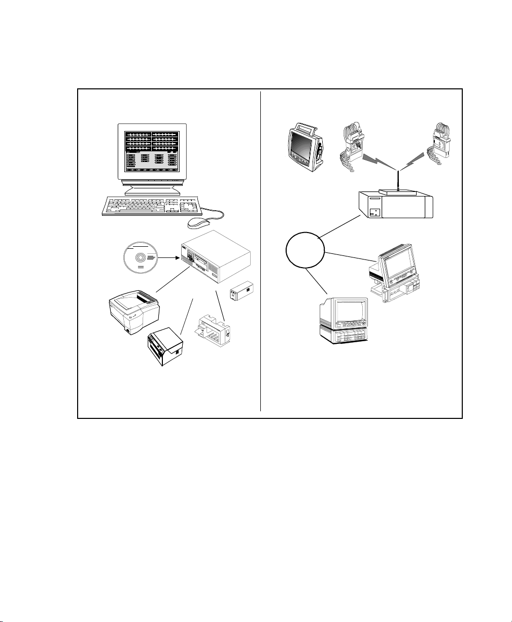
The IntelliVue Information Center
Information Center
Information Center
Information
Center Software
Printer
Workstation
4-Channel
Recorder
NT
2-Channel
Recorder
UPS
Point-of-Care Equipment
Philips Telemetry System
Philips
CareNet
Switch
Philips Compatible
Bedside Monitors
Philips Patient Care System with CareNet
Introduction to the Information Center
1-3
Page 22
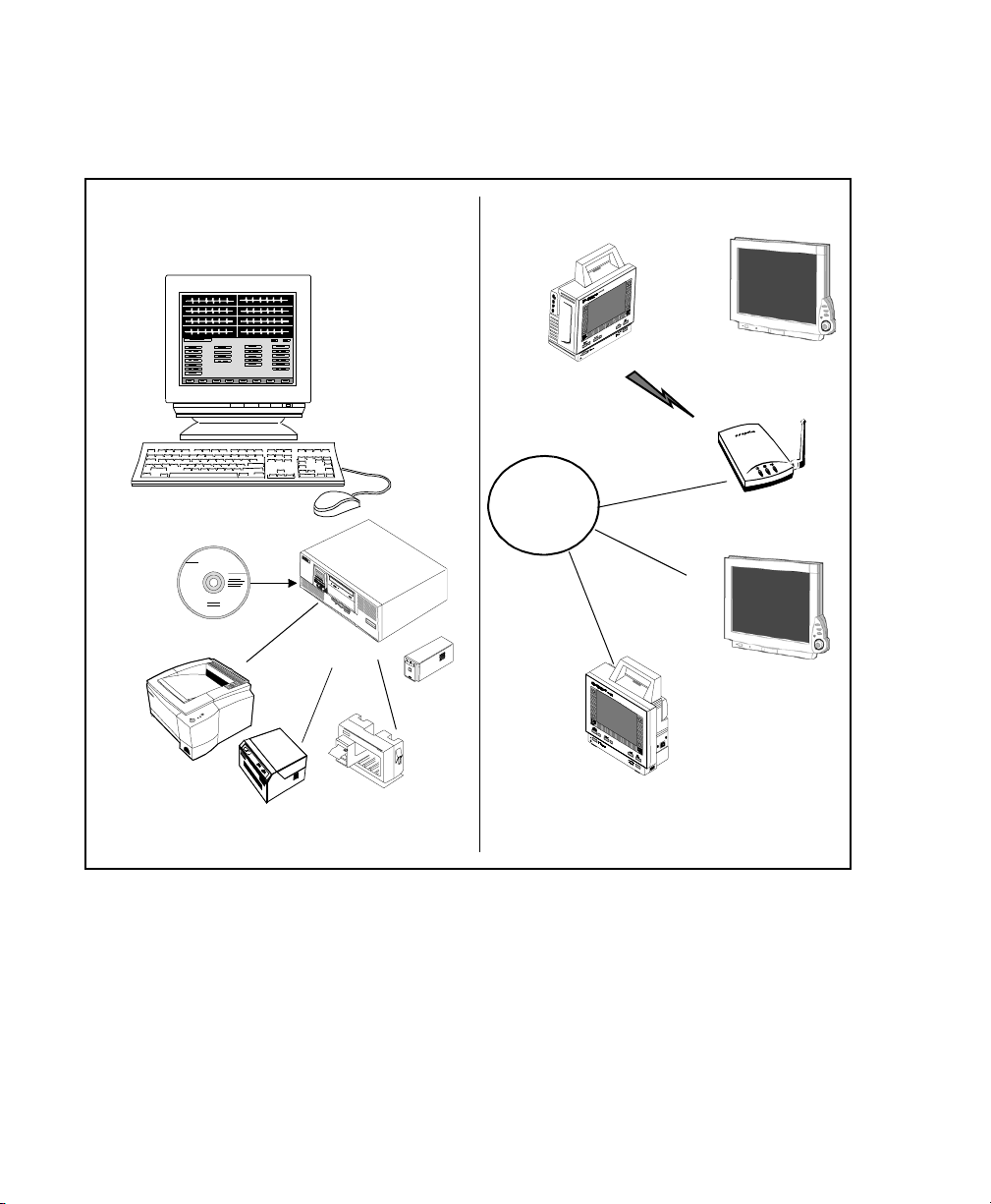
The IntelliVue Information Center
Information Center
Information Center
Information Center
Software
Printer
NT
Workstation
UPS
Point-of-Care Equipment
IntelliVue
Clinical N et w ork
Switch
Wireless M3 /In te lliV ue
Patient Monitors
Access Point
Wired M3/IntelliVue
Patient Monitors
4-Channel
Recorder
2-Channel Recorder
Philips Patient Care System with IntelliVue Clinical Network
1-4 Introduction to the Information Center
Page 23

The IntelliVue Information Center
IntelliVue Clinical Network with Database Server
The IntelliVue M3185 Clinical Network with the M3154 Database Server or the
M3169 Database Server, enables transmission of data between centrals,
providing access to both real-time and stored data within and across clinical
units. The patient data storage includes full disclosure waveforms and
physiologic parameters for up to 48 hours per patient, up to 4 waves per patient,
and up to 150 30-second alarm records and saved strips, with up to 4 waves per
event.
The IntelliVue Clinical Network with the M3169 Database server stores data for
up to 48 pati ents and supports up to 3 M3150 Information Centers for
monitoring patie nts and up to 3 M3151 Information Center Cl i ent s f or revi ewi ng
patient d a t a .
The IntelliVue Clinical Network with the M3154 Database Server stores data for
up to 96 pati ents and supports up to 8 M3150 Information Centers for
monitoring patie nts and up to 8 M3151 Information Center Cl i ent s f or revi ewi ng
patient d a t a .
The IntelliVue Clinical Network is based on industry standard component s and
cabling.
The following illustration shows an example of a IntelliVue Clinical Network
connecting centrals in separate clinical units.
Introduction to the Information Center
1-5
Page 24
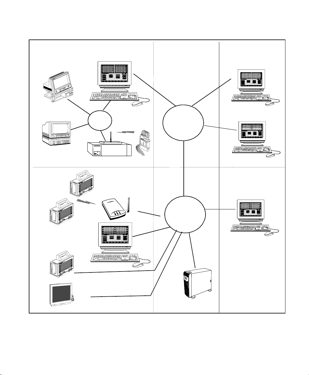
The IntelliVue Information Center
e
CCU
Philips
Compatible
Bedside Monitors
ED
Wireless
M3/IntelliVue
Patient
Monitors
Information
Center
Philips
CareNet
Switch
Philips Telem etry System
Access Point
Intellivue
Clinical Network
Switch 1
Intellivue
Clinical Netwo rk
Switch 2
Work Area
Information
Center Client
Information
Center Client
Physician’s Offic
Information
Center Client
Information
Center
Wired M3/IntelliV ue
Patient Monitors
Philips Patient Care System with IntelliVue Clinical Network and
Database Server
1-6 Introduction to the Information Center
M3154/M3169
Database Server
Page 25

The IntelliVue Information Center
Large Network Central Database System
The Large Network Central D atabase System a l lows up to 10 M3154 Database
Servers to be interconnected on the hospital network. This connectivity provides
clinicians with the ability to transfer patients across care units that are on
separate database servers. In addition, for systems with the M3185 Application
Server, the Large Network Central Database System allows you to view, through
the Information Center Web Access, near-realtime waves, parameters and
alarms, as well as review all retrospective data for up to 960 patients across care
units that are on separate database servers (see “Information Center Web
Access” on page 6-62).
The following illustration shows an example of a Large Network Central
Database System.
Introduction to the Information Center
1-7
Page 26
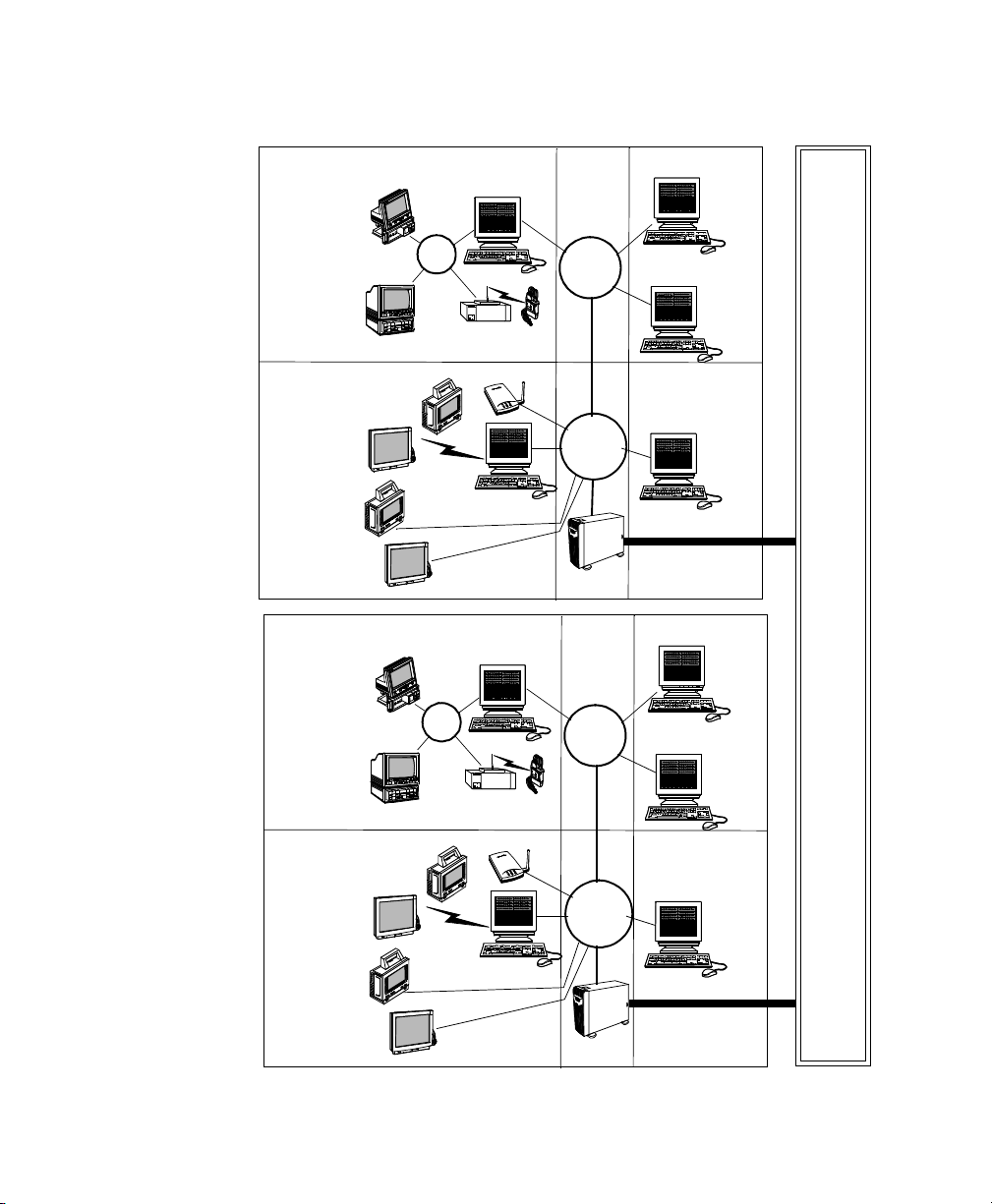
The IntelliVue Information Center
CCU
Philips
Compatible Bedside
Monitors
ED
Wireless
M3/IntelliVue
Patient Mon itors
Wired M3/IntelliVue
Patient Monitors
ICU
Philips
Compatible Bedside
Monitors
Information
Philips
CareNet
Switch
Philips Telemetry
Access Point
Information
Information
Philips
CareNet
Switch
Center
System
Center
Center
IntelliVue
Clinical
Network
Switch
IntelliVue
Clinical
Network
Core
Switch
M3154
Database
IntelliVue
Clinical
Network
Switch
Work Area
Information Center
Clients
Physician’s
Office
Information
Center Client
Work Area
Information Center
Clients
Hospital Network
Stepdown
Wireless M3/IntelliVu e
Patient Monitors
Wired M3/IntelliVue
Patient Monitors
Philips Patient Care System with Large Network Central Database
System
1-8 Introduction to the Information Center
Philips Telemetry
System
Access Point
Information
Center
IntelliVue
Clinical
Network
Core
Switch
M3154
Database
Physician’s
Office
Information
Center Client
Page 27

Intended Use
Intended Use
The intended use of the Information Center Software is to display physiologic
waves, parameters, and trends, format data for strip chart recordings and printed
reports, and provide the secondary annunciation of alarms from other networked
medical devices at a centralized location. The Information Center Software
provides for the retrospective review of alarms, physiologic waves and
parameters from its database.
An additional intended use of the Information Center Software is to provide
primary annunciation of alarms and configuration and control access for
networked telemetry monitors.
This product is not intended for home use.
Rx only.
Introduction to the Information Center
1-9
Page 28

The Information Center Features
The Information Center Features
The Information Center Software allows you to:
• View waves and physiological parameter information sent over the
monitoring network. Up to 24 waves can be displayed on a si ngle main
screen. Up to 32 waves can be displayed on dual displays with two main
screens.
• Be alerted to patient alarms that have been detected by networked
monitoring devices and respond to the alarms.
• Perform ST/AR multilead arrhythmia analysis on up to two leads of ECG.
ST/AR ST segment monitoring provides ST elevation and depression
measurements for telemetry-monitored patients.
Note—ST/AR analysis for M3 and IntelliVue Patient Monitors is done at
the monitor. ST analysis for all bedside monitors is done at the monitor.
• Make strip chart recordings on a Philips Recorder and (if a printer is
available) printed reports requested from the point-of-care and/or the
Information Center.
• Access a retrospective review of up to 48 hours of patient data, including
full disclosure waves and parameters, alarms, ST segments, events, trends,
EASI derive d reconstructe d 12 lead ECG and captured conventional 12
lead ECG.
• View real-time data for a patient being monitored by another Information
Center connected via Philips CareNet. If connected via the IntelliVue
Clinical Network, you can view both real-time and stored data for a
patient monitored on another central, and that central can be in the same
clinical unit or in another unit.
• Provide the clinical operator with secondary notification of patient alarms
and wave snippets on a small paging device through the integration of the
Data Critical Statview
with the Information Center.
1-10 Introduction to the Information Center
™ paging syst em (avai lable in limited geographi es)
Page 29

The Information Center Feature s
• Provide the management of grouping of beds per nursing assignment
(‘Care Groups’). A single Care Group is typically named for a caregiver
who is responsible for multiple patients within a single care unit. A Care
Group can be assigned a color that will display as the background for the
bed label on the Information Center. Color by Care Group helps the
caregiver to quickly identify beds within their Care Group.
• Export ECG waveform data from the Information Center to an Zymed
Holter for Windows
™ - Model 2010 for analysis.
Recordings and Reports
Point-ofCare
Equipment
Recordings can be requested from the Information Center or from networked
products.
If a printer is connected, reports requested from the Information Center or from
networked products can be printed.
The Information Center communicates with the following monitoring devices:
• Bedside monitors: IntelliVue Patient Monitor, CMS, V26 and V24, M3
(wired and wireless), and Compact Configurable Monitor 78352C/54C.
Note—In this book the term “M3” refers to Revision D.0 of the M2, M3,
and M4 bedside monitors. Differences in features or functionality are
called out where appropriate.
• Philips Telemetry System and Hewlett-Packard M1403 Digital UHF
Telemetry System with Option C03. The telemetry system must be
Release C or greater. If the Philips transmitter is connected to the
TeleMon bedside monitor, it is referred to as “docked”.
Introduction to the Information Center
1-11
Page 30

The Information Center Features
The Information Center provides the following functionality for point-of-care
equipment connected via Philips CareNet or the IntelliVue Clinical Network.
M3 Bedside
Monitors
Function
connected via
the IntelliVue
Clinical Network
Bedside
Monitors
connected via
Philips CareNet
Telemetry
IntelliVue
Patient
Monitors
connected
via the
IntelliVue
Clinical
Network
Central monitoring
(patient management
alarm annunciation,
etc.)
ST/AR Arrhythmia
monitoring at the
central
Arrhythmia control
and review at the
bedside.
ST/AR ST segment
monitoring at the
central
Yes Yes Yes Yes
No -- provid ed by
bedside monitor.
Yes Yes Yes -- ST/AR
Arrhythmia
functionality is
available at the
central but is
provided by the
bedside
monitor.
Arrhythmia contro l
is at the bedside;
review is available
Yes - CMS patient
monitors must be
Rev. C or greater.
N.A. Yes
at the bedside and
at the central.
No - if present, ST
segment
monitoring is
provided from the
bedside.
Yes - with limited
functionality at the
Information
Center.
Yes No - if present,
ST segment
monitoring is
provided f rom
the bedside.
Primarily provided
from the bedside.
1-12 Introduction to the Information Center
Page 31

Function
M3 Bedside
Monitors
connected via
the IntelliVue
Clinical Network
Bedside
Monitors
connected via
Philips CareNet
The Information Center Feature s
IntelliVue
Patient
Monitors
Telemetry
connected
via the
IntelliVue
Clinical
Network
ST trends and waves
in ST Review
TM
EASI
ECG
capability
Central printing of
recordings and repo rts
requested from the
point-of-care
Yes Yes Yes Yes
No Yes - CMS patient
Yes Yes
monitors must be
Rev. B.0 or greater.
V26 and V24
monitors must be
Rev. C.0 or greater.
Yes
Note—Reports are
not available if
requested from M3
wireless monitors
to be printed at the
central printer.
However, they can
be printed on a
Yes Yes -
recordings via
patient button
on transmitter
(if configured)
or from
TeleMon (if
transmitter
docked).
local printer.
EASI is a trademark of Zymed Inc.
Yes
Introduction to the Information Center
1-13
Page 32

Information Center Display Screens
Information Center Display Screens
The Information Center has two types of screens on the display:
• The Main Screen, or resting display, (illustration below) which has patient
sectors; no windows are open.
• The Patient Window, which displays data for a patient. You perform most
tasks either on the Patient Window or other application windows that you
access from the Patient Window.
Main Screen The Main Screen displays real-time waves, numerics, and alarms from multiple
patients. It can be configured to show up to 32 waves in either single - or dualcolumn configurations.
System
Message Area
System Message Area
xx xxxxxxxxx xx xxxx
xx
ll
xx
xxx x
Sectors
l
ll
xx
xxx x
l
ll
xx
No Bed
XX XX
53
xx xx
54
xx
xx
54
XX XX
60
xx
0
xx
xxx x
l
0
ll
xx
xx
0
xx
0
Date and Time
xxxxx
XX XX
53
xx
59
XX XX
60
XX XX
53
0
xx
0
0
0
Main Screen
An area at the top of the screen displays system status messages, date and time
and any name that may be associated with this central, for example, “CCU
Hallway1”.
1-14 Introduction to the Information Center
Page 33

Information Center Display Screens
Patient
Sectors
Up to 16 patients can be displayed on the Main Screen. The number of waves
and amount of information in a sector depends on the size of the sector. All
waves are 3.3 seconds in length in a dual-column format and 7.0 seconds in
length in a single-column format (at 25 mm/s speed -- waves at 12.5 mm/s are
twice as long).
In addition to the bed label, waves, and numerics, the information that displays
in a sector can include:
• Patient name, if configured.
• Heart Rate alarm limits, if configured (not available for M3 monitors).
• First line of screen notes, if configured.
• Paced indicator (if set).
• Alarms off indicators and alarm and INOP messages (if applicable).
• The icon to the right of the bed label for telemetry monitored patients.
Note—If the telemetry transmitter is docked at TeleMon, the icon will
have a box around it.
• If the M3 or IntelliVue Patient Monitor is connected to a wireless
IntelliVue Clinical Network, there is a wireless equipment icon to the
right of the bed label.
• An “*” to the left of the bed label for overview beds (see page 1-28).
• A in the upper right-hand corner to indicate that a conflict exists
between patient data at the Information Center and patient data at the M3
or IntelliVue Patient Monitor.
When the cursor is positioned over the bed label, the following information is
displayed:
• Transmitter number, if telemetry monitored.
• Monitor label (number), if M3 or IntelliVue Patient Monitor.
When the Patient Window is open, the bed label in the sector for the open
Patient Window has a dashed line around it. For beds assigned to a Care Group
(see “Care Groups” on page 2-12) the bed label in the patient sector will display
the selected color as the background for the bed label. For beds not assigned to a
Care Group, or beds who have the color black assigned, the bed label has white
text on black background.
Introduction to the Information Center
1-15
Page 34

Information Center Display Screens
Patient Sec tor
Buttons
All tasks start in the patient sector. Normally, there are no buttons visible in the
sector. Buttons in the sector are activated when the cursor is in the sector. The
sector is then outlined, and the buttons become visible.
There are two buttons available from the patient sector. One is the
Window
button, which accesses the Patient Window. The other depends on how
Patient
your system is configured. The following table explains the button labels.
Condition Button Label Action when Button Clicked
No alarm
pending
Record
Starts a delayed non-continuous (timed)
recording (can also click anywhere in the
sector except the Patient Window button).
Save
Generates the saving of a 30-second strip
in Alarm Review (can also click
anywhere in the sector except the Patient
Window button).
Record and Save
Starts a delayed non-continuous (timed)
recording as well as the saving of a strip
(can also click anywhere in the sector
except the Patient Window button).
Alarm pending
Silence
Turns the alarm sound off, and the sector
changes to its normal color (can also click
anywhere in the sector except the Patient
Window button).
Silence/Review
Turns the alarm sound off and the sector
changes to its normal color and opens a
Patient Window with the Fast Alarm
Review for that alarm.
Note—Can click anywhere in the sector
(except on a button) to turn the alarm
sound off without displaying the alarm.
Note—Your central may be configured to not allow silencing of bedside
alarms at the Information Center. In this case a Silence button will only appear
for telemetry beds. In the case of M3 and IntelliVue Patient Monitors, alarms
can be silenced at the central if both the central and M3 or IntelliVue Patient
Monitor are configured with remote silence enabled. If this is not the
configuration, the Silence button is present at the central, but is not active.
1-16 Introduction to the Information Center
Page 35

Information Center Display Screens
Condition Button Label Action when Button Clicked
Bed in Standby
Resume
monitoring
Bedside Monitor (other than M3 or
IntelliVue Patient Monitor): button is
greyed out, indicating that monitoring
must be resumed at the bedside.
Telemetry, M3, and IntelliVue Patient
Monitors: takes the bed out of Standby,
and the button reverts to t he no rmal label .
Note—If the transmitter is docked at
TeleMon, the bed cannot be put in
Standby.
Note—If there is no bed assigned to a sector, the Sector Setup button is
displayed instead of the Patient Window button. Cl icki ng this button accesses
the appropriate page of the Sector Setup Window.
Introduction to the Information Center
1-17
Page 36

Information Center Display Screens
s
System Message Area
Patient Window
Single Display When a Patient Window or an application window is open, all the patient sectors
are still visible in the top half of the screen, but are compressed (see the
illustration below). The Patient Window allows you to view up to 4 waves at a
time.
Date and Time
XXX
XXXXXXXX XXXX
XXX
XX
XX
54
XX
XX
59 0
XX
XX
60
XX XX
53
XXX
XXX
XXXX XXXXX
XXX
XXX
XXX
0
XXXXX
XXXXX
XXXX
XXXXX
XX XXXX
XXXXX
Patient Window
0
0
0
Compressed
Patient Sectors
Basic
Task
Buttons
XX XXX XXX
XX
l
ll
XXx
l
ll
XX
l
ll
XX
l
XX SS SSSS
XXXX
XXXX
XXXX XXXX
l
Application Button s
XX
XX
XX
XX
XXXXX XXX
53
54
54
60
XX
l
XX
ll
0
XX
XX
0
l
XX
XX
0
XXXXSSS XXXXXXXX
XXX
XXX
54
XX
XX
54 0
XX
XX
0
Display with Patient Window Open
Dual Displays Dual displays offer the advantage of enabling clinicians to view the Patient
Window and the data review applications on a full screen. You can view up to 7
waves at a time (may be up to 6 with EASI ECG). A dual display system can be
configured with one or with two main screens.
Patient
Window
Buttons
Basic
Task
Button
1-18 Introduction to the Information Center
Page 37

Information Center Display Screens
One Main Screen
One display is used for the Main Screen, and the other is used for a full-screen
Patient Window or application window.
Two Main Screens
• Both displays have patient sectors when Main Screen is active. For
example, for a 16-patient central, the Main Screen of each display
includes 8 sectors. This feature is available for 8, 12, and 16-patient
centrals.
• When an application window is open, all the sectors move to one display,
and the second display has the full-screen application window. To remove
the application window, click the Main Screen button.
Main Screen
Application
Window open
53
53
53
53
53 0
53 0
53 0
0
0
0
0
53
53
53
53
53 0
53 0
53 0
0
0
0
0
54
0
Introduction to the Information Center
1-19
Page 38

Information Center Display Screens
Information/
Icons on the
Patient
Window
Adjustments
on the Patient
Window
Some of the information/icons that can be displayed in the patient secto r also
appear on the Patient Window:
• Telemetry icon -- upper left corner
• Wireless bedside icon -- upper left corner
• Screen Notes (if available) -- all text that was entered in the Admit
Window -- bottom of sector
• Paced indicator (if applicable) -- upper left corner
Depending on the equipment assigned to a sector, clinicians can make the
following adjustments on the Patient Window to parameters:
• Telemetry beds
– the lead/label for the primary and secondary ECG lead
– the size of the primary and secondary ECG waves (on the display
and recordings)
– the heart rate alarm limits
– SpO2 alarm limits (if SpO2 is on)
• Bedside monitors with EASI ECG capability
– the size of the primary and secondary ECG waves (on the central
display and recordings)
• IntelliVue Patient Monitors
– the size of the ECG waves (on the central display and recordings)
– the heart rate alarm limits
Note—If EASI EC G is being used, t he label “EASI” is displaye d below the
primary waveform.
Patient
Window
The Patient Window provides the following buttons that allow you to perform
actions within the Patient Window:
Buttons
Button Description
Continuous Recording Allows you to select waves to continuously
Stop Stops any continuous recording in progress.
1-20 Introduction to the Information Center
record.
Page 39

Information Center Display Screens
Button Description
Suspend Alarms and
Unsuspend Alarms
Suspends/unsuspends alarms at the
Information Center.
(telemetry only)
NBP Alarms
(telemetry docked at TeleMon
only)
Arrhythmia Analysis Displays up to two “live” delayed waves,
Allows you to adjust NBP alarms.
with beat labels. The beat labels represent
analysis of both the primary and secondary
waves. See Chapter 5, “ST/AR Arrhythmia
Monitoring” for additional information on
arrhythmia monitoring.
Multilead ECG
(if not using EASI ECG)
Displays a snapshot of up to six leads of
ECG, plus a 10-second rhythm stri p. You can
use this window to verify that the ECG
waves are optimized for arrhythmia
monitoring.
12-Lead ECG
(if using EASI ECG)
Displays the 12 leads derived from the EASI
ECG system, plus a 10-second rhythm strip.
From this window, you can print a 12-lead
report.
More Waves Displays additional waves, if available. If
none available, displays the Arrhythmia
analysis data (see “Arrhythmia Analysis”,
above).
Introduction to the Information Center
1-21
Page 40

Information Center Display Screens
Application
Buttons
When the Patient Window or an application window is open, a “task bar” at the
bottom of the screen allows access to other Information Center applications for
that bed. There are two rows in the task bar.
Top Row
The buttons in the top row change with the active application to provide access
to related applications. The buttons in the table below appear on the Patient
Window.
Button Description
Discharge Accesses the Discharge Window to clear the patient data and
return alarm limits controlled at the central to unit settings.
Sector Setup Accesses the Sector Setup Window to clear the sector and
assign an overview bed. Additional functionality depends on
whether the central is fixed or flexible. See “Fixed and
Flexible Monitoring” on page 2-26.
Standby Accesses the Standby Window, enabling you to suspend
monitoring for telemetry, M3 beds, and IntelliVue Patient
Monitors when the patient is temporarily off the unit or out
of antenna range. Enables you to resume monitoring when
the patient returns.
For bedside monitors other than the M3 or IntelliVue Patient
Monitor, you must put bedside monitor in Standby and
resume monitoring at the bedside.
Wave Review Accesses full disclosure.
1-22 Introduction to the Information Center
Page 41

Information Center Display Screens
Bottom Row
The buttons in the bottom row are available no matter which application is
active.
Button Description
Basic Task
Buttons
Arrhythmia Alarms
Accesses a window to adjust arrhythmia monitoring
for a patient. This button is not available for M3
monitors
Trend Review
Alarm Review
Admit
Accesses graphical and/or tabular trends.
Accesses stored alarm events and user-saved strips.
Accesses the Admit Window to enter the patient name
and other data.
All Controls
Provides access to the full array of clinical and support
functions.
Note—A list of the applications associated with each button is displayed when
the mouse cursor rests on the button for approximately 10 seconds.
In addition to the buttons in the task bar, the following basic task buttons are
always available, no matter which window is open.
Button Description
Main Screen
Closes the open window and b ri ng s you b ack t o t he
resting display.
Patient Window
Patient List
Brings up the Patient Window when another
application is open.
Allows you to switch the patient in the open
window (the application does not change). See
“Viewing a Bed Temporarily” on page 1-28.
Introduction to the Information Center
1-23
Page 42

Using Standby
Button Description
Using Standby
Telemetry, M3 and IntelliVue Patient Monitors
Print
Help
Standby is used to suspend monitoring for a patient. Control of the Standby
function depends on the monitoring device being used.
Standby is used to temporarily suspend monitoring, for example, when the
patient goes out of antenna range. In addition, when the patient is discharged,
the bed can be put in Standby until the new patient is connected.
If a printer is available, starts a printout of the
screen or a report. This key is avail abl e only for t h e
Arrhythmia Analysis and Multilead ECG Patient
windows, data review applications, and unit
settings windows.
Note—If a printer is not available or is not
configured, the print key is greyed out.
Brings up the on-l ine Hel p Wind ow (see “U sing the
On-line Help/Quick Guide” on page 1-35).
1-24 Introduction to the Information Center
Page 43

Using Standby
Task Summary Place the bed in Standby and resume monitoring by performing the following
steps:
Step Action
1 On the Patient Window, click the
appropriate location, then on
Standby button. Click on the
Suspend Monitoring. The message
“TELEMETRY STANDBY” or “MONITOR STANDBY” and
location, if selected, are displayed in the sector.
2 The bed can be taken out of Standby by placing the cursor in the
Other Bedside Monitors
sector and clicking on the
The bed is put in Standby and taken out of Standby at the bedside monitor. At
the central, you can select the location that is displayed in the sector, along with
the Standby message.
Resume Monitoring button.
Task Summary Select the Standby location by performing the following steps:
Step Action
1 On the Patient Window, click the
location from the list.
The “MONITOR STANDBY” message and
Standby button. Select the
location, if selected, are displayed in the sector.
Note—At the central, when the cursor is placed in the sector, a
Resume Monitoring button is available. Clicking on it reminds you
to take the bed out of Standby.
Introduction to the Information Center
1-25
Page 44

EASI 12-lead Review and Report
EASI 12-lead Review and Report
If the monitoring device has EASI 12-lead capability, you can view all available
leads from the Patient Window. In addition, you can request a 12-lead report.
Note—EASI derived 12-lead ECG’s and their measurements are approximations
to conventional 12-lead ECG’s and should not be used for diagnostic
interpretations.
Task Summary
Display the 12-leads and print a report by performing the following steps:
Step Action
1 On the Patient Window, click the
second ECG wave is displayed for each of the derived 12 leads.
Note—It is not possible to display the derived 12-lead waves if there
is an INOP condition in any lead. To view the EASI AI, AS, and ES
leads, click on 3 EASI Leads.
12-Lead ECG button. A 2.5
1-26 Introduction to the Information Center
Page 45

Step Action
2To:
• View the most recent ECG data -- click
• Change the wave layout -- click on the wave layout on the top
right side of the window then select wave format (3x4, 6x2, or
12x1) from the list that displays. In 3x4 layout an additional
rhythm lead displays.
• Change the size of the waves -- click on the cal bar and select
the size of the wave you want from the list that displays (x1/2,
x1, x2, x4).
• Change the wave speed (25 mm/s or 50 mm/s) -- click on the
speed on the bottom right of the window and select the speed
from the list that displays. When you select a different speed the
window re-displays with the selected speed.
EASI 12-lead Review and Report
Update Waves.
3 To print a report click the
Print button at the top of the window. The
report shows all of the monitored vital signs, the 12 leads, and the
high pass and low pass bandwidth frequencies with:
• 3 rows x 4 columns -- showing 12 2.5-second waves and a 10second rhythm strip at the bottom of the page
• 6 rows x 2 columns -- showing 12 5-second waves
• 12 rows x 1 column -- showing 12 7-second waves.
Introduction to the Information Center
1-27
Page 46

Viewing Other Patients over the IntelliVue Clinical Network
Viewing Other Patients over the Inte l liVue Clinica l Net wor k
Information Centers and Clients on the IntelliVue Clinical Network enable you
to view both real-time and stored patient data for patients monitored by other
centrals on the IntelliVue Clinical Network.
There are two ways to do this:
• View the bed temporarily, in the Patient Window
You select the patient via the Patient List. You can then monitor the
patient or review the data for that bed until you change to another patient
or go to the Main Screen. If configured, you may also be able to admit,
discharge, and transfer data for that bed.
or
• Overview a bed in a sector on your central
You use Sector Setup to overview a bed that is monitored by another
networked central. The actions allowed for overvi ew beds depend on how
the system is configured. See “Types of Access” on page 1-29.
Viewing a Bed Temporarily
Task
You can view data temporarily for any bed monitored by another networked
central. This feature enables you to view patients that are in other clinical units
or that are being monitored by another central in your un it.
View other patients temporarily by performing the following steps:
Summary
Step
1-28 Introduction to the Information Center
Action
1 Click the Patient Window button in any sector to bring up a Patient
Window.
2 On the Patient Window, click the bed label at the left in the title bar
to display the Patient List. The beds listed are those that are
displayed on this central.
Page 47

Viewing Other Patients over the IntelliVue Clinical Network
Overview Beds
Step
You can overview a bed on your Main Screen that is monitored by another
networked central. See Chapter 2, “Patient Management” for information on
assigning overview beds.
Action
3 Click the button to the left of the Patient List for the unit you want.
The Patient List will now contain all beds currently monitored in the
unit you selected.
Note—Click on your unit name to access patients on other centrals
in your unit.
4 Click on the bed you want. That patient’s data will be displayed in
the Patient Window. You can then access any other window for that
patient.
5 You can then access data for another patient or click Main Screen to
remove the window.
Note—You don’t have to return to the Patient Window. For
example, if you are on the Alarm Review Window, you can remain
there and change the patient you are viewing. Other windows you
access will then be for that patient.
Types of Access
Each central on the IntelliVue Clinical Network can be configured to specify the
following types of access control of beds monitored by another central:
• Full Control (read-write) access -- you can view patient data and change
measurement controls (such as alarm limits).
– Telemetry Setup controls are for that central only.
– Functions that affect the central as a whole, rather than a specific
bed, such as volume control are accessible for the local central only.
• Read-Only access -- you can view patient data, but measurement controls
cannot be changed. The controls that are available are:
– Record button in the Patient Sector
– Continuous Recording in the Patient Window
– Arrhythmia Analysis Windows -- Update Waves (but not Relearn)
– Alarm Review -- navigation and record or print alarm.
– Event and Wave Review -- navigation.
Introduction to the Information Center
1-29
Page 48

Consulting Beds over the Philip s CareN et
– Trend Review -- navigation.
– ST Review - - navigation, superimpose
– Record All (from All Controls)
– Sector Setup
• No access -- you cannot access any bed on that central.
Full Control if Multiple Viewers
Since more than one Information Center can have access to a bed at the same
time, there may be situations when two or more clinicians are viewing
information for the same patient at the same time. If multiple clinicians have full
control access to the same patient, then, in general, the last operation wins.
Consulting Beds over the Philips CareNet
If you have a Information Center on the Philips CareNet and you have flexible
monitoring configured, you can view real-time patient data for patients
monitored by other centrals on the same CareNet. You do this by assigning a
sector as a consulting bed.
Consulting Beds
To assign a consulting bed, you assign a sector on the Main Screen to display
that bed. You can use either an empty sector, or you can clear a sector that is
currently being used. See “Assigning a Bed and/or Equipment to a Sector” on
page 2-27 for a task summary.
The following functions are available from consulting beds:
• Main Screen: same as monitoring central, except there will not be a
pacing indicator. You can make a recording from the patient sector -- you
cannot save a strip (if the system is configured for Save or Record and
Save from the sector). You can also silence alarms.
• Alarm recordings (as configured in the consulting central’s Record/Store
Unit Settings).
– If a yellow alarm condition persists after the inhibitory period ends
and the alarm is generated again, that alarm will not produce a
recording at the consulting central.
– If there are multiple red alarms, the consulting central records the
highest priority alarm.
1-30 Introduction to the Information Center
Page 49

Consulting Beds over the Philips CareNet
• Patient Window: controls for Continuous Recording, the Patient List,
Main Screen button, and All Controls button.
Note— For EASI monitored patients, the leads displayed are fixed at lead
II and V2. The ST values correspond to primary and secondary ECG
waves displayed at the monitoring central and are reflected as ST 1 and
ST 2.
For non-EASI monitored patients, the leads and ST values correspond to
the primary and secondary ECG waves displayed at the monitoring
central.
• Sector Setup Window: Clear Sector tab (if bed assigned), or Assign Bed/
Equipment tab (if no bed assigned).
• All Controls: Sector Setup button, Volume Control butto n, ser vice-related
applications.
• The on-line Help function is available, where applicable.
Guidelines for Ensuring Correct Data
If a bed is monitored by one Information Center and is a consulting bed on
another Information Center, it is important to ensure that patient data is labeled
correctly. To do this, follow the guidelines listed below. For these examples, the
monitoring (primary) central is “Central 1” and the consulting central is “Central
2”.
On Central 1, when you are going to begin monitoring a new
patient:
1. On Central 2, use
Clear Sector in Sector Setup to clear any consulting
sectors that have the bed label or the equipment for the new patient.
2. On Central 1, admit the patient.
3. On Central 2, use
Assign Bed and Equipment in Sector Setup to assign
the new patient’s bed and equipment.
On Central 1, before you change the equipment and/or bed label for
this patient:
1. On Central 2, use
Clear Sector to empty the sector that is consulting the
patient.
2. On Central 1, make the changes (bed, equipment, or both) for the patient.
3. On Central 2, use
Assign Bed and Equipment in Sector Setup to assign
the same bed and/or equipment for the patient.
On Central 1, before you discharge this patient:
On Central 2, use
Clear Sector to empty the sector that is viewing the patient.
Introduction to the Information Center
1-31
Page 50

Optimizing Wireless System Performance
Optimizing Wireless System Performance
Bedside monitors with a wireless connection to the IntelliVue Clin ical Network
have their advantages, however the flexibility the wireless link offers is not
without its challenges. The reliability and quality of the wireless signal
transmission through the air and hospital walls are governed by a number of
variables that can be difficult to control. A wireless connection from a bedside
cannot be as dependable as a wired connection.
The effect of low signal strength and interference on the display of the patient
information from a wireless bedside at the central station can range from a
momentary period to a lengthy period of data loss. Although data loss due to the
wireless link may be occurring at the central station, monitoring and alarming
continue at the bedside (this differs from telemetry where monitoring and
alarming occur in the central station, so when data loss due to the wireless link
occurs, monitoring cannot continue).
Minimizing Data Loss
Low Signal
Strength
Interference
1-32 Introduction to the Information Center
In order to minimize data loss at the central station due to low signal strength
and interference, there are several things a hospital should do.
Devices called “Access Points” are used to receive the radio signals from the
bedsides. A wireless bedside must be within the coverage area of an associated
access point for proper operation. When a wireless bedside is taken out of the
designated coverage area, data loss at the central station will increase.
WarningWarning
Various equipment and/or electrical or medical devices that operate in the
2.4 to 2.48 GHz range could interfere with radio transmission of important
medical data to the central station. Facilities utilizing wireless devices need
to manage the use of these devices for safe operation.
The effect of interference on the amount of data loss at the central station
depends on the strength, type and proximity of the interfering device to the
wireless bedside or access point. Any wireless device operating between 2.4 and
2.48 GHz can cause interference with the monitoring wireless network. Likely
sources of interference include microwave ovens, other vendors’ wireless
Page 51

Optimizing Wireless System Performance
networks, wireless telephone headsets, certain cellular telephones, handheld
computers, transceiver devices, and Bluetooth devices . In cases where the sou rce
of interference is known, removing the device or moving it away from the
wireless bedside or access point will improve the system’s performance.
Since the wireless network used for monitoring emits radio frequencies, it is also
possible for it to interfere with other devices (for example, programmers for
cardiac pacemakers). Contact the manufacturers of other equipment used in the
vicinity of the monitoring wireless network for information on possible
susceptibility to these frequencies.
It is the hospital’s responsibility to keep track of all of the wireless devices in
use in the hospital, and manage their use for safe operation.
Wireless System Messages
Message Possible Cause What to Do
Excessive
wireless data
loss
Excessive
wireless
interference
The system continually monitors the signal quality sent from wireless monitors.
When data transfer from one or more monitors across the wireless link is
compromised due to interference or too many transmitting devices, the system
displays one of the following messages at the top of the screen.
Data loss (no signal or excessive
dropout of signal) because of too
many monitors using an Access
Point, excessive interference, or
weak signal.
Dropout of signal on one or more
monitors due to interference of the
signal, e.g., microwave oven
interference.
• Turn off unused monitors.
• If a microwave is in use, move
• Locate and remove source of
• If condit ion persists, contact
• Make sure all microwave
• Turn off unused monitors.
• Locate and remove source of
• If condit ion persists, contact
monitors away from the
microwave signals.
interference.
service.
ovens are turned off or at least
20 feet from the monitors.
interference.
service.
Introduction to the Information Center
1-33
Page 52

Configuration
Message Possible Cause What to Do
Weak radio
signal
Configuration
Excessive occurrence of dropped
messages and weak (wireless) radio
errors have occurred between one or
more wireless M3/M4 bedsides and
an access point. This could happen
due to a device being marginally out
of range of an access point or
because of some signal attenuator,
for example a monitor being behind
a large metal cabinet.
The Information Center Software is shipped with factory defaults. At
installation, (or at any time after installation), the Information Center Software
can be configured with defaults for the unit in which it is installed.
In addition, adjustments such as changes to alarms being stored and recorded
can be made on a per patient basis.
• Move the monitor within
range of an access point.
• If condit ion persists, contact
service.
See Chapter 9, “Information Center Configuration,” for a list of factory defaults
and configuration choices.
1-34 Introduction to the Information Center
Page 53

Using the On-line Help/Quick Guide
An on-line Help feature is a Quick Guide that is always available to answer
questions and provide information on using the Information Center.
There are two types of information available:
• Context-Sensitive: This is information you get when you first click the
Help button. It tells you about the window you’re looking at.
• Task and Problem-Solving Quick Guide: This is infor mation on
performing tasks and troubleshooting problems. To get to this type of
information, click Quick Guide on any Help Window. You’ll get the
Quick Guide Menu. Click on an item to get to that topic.
In the Help windows, text in green (and underlined) indicates that you can click
on it and get more information.
Note—To print a topic, click the right mouse button and select Print Topics.
Using the On-line Help/Quick Guide
Introduction to the Information Center
1-35
Page 54

Using the On-line Help/Quick Guide
1-36 Introduction to the Information Center
Page 55

2
Patient Management
This chapter describes how to manage p at ient data us i ng the Information Center.
It includes the following sections:
• Introduction. . . . . . . . . . . . . . . . . . . . . . . . . . . . . . . . . . . . . . . . . . . . . . 2-2
• Admitting a Patient. . . . . . . . . . . . . . . . . . . . . . . . . . . . . . . . . . . . . . . . 2-3
• Changing Patient Information. . . . . . . . . . . . . . . . . . . . . . . . . . . . . . . . 2-8
• Resolving Conflicts with M3 or IntelliVue Patient Monitors . . . . . . . 2-9
• Care Groups . . . . . . . . . . . . . . . . . . . . . . . . . . . . . . . . . . . . . . . . . . . . 2-12
• Discharging a Patient . . . . . . . . . . . . . . . . . . . . . . . . . . . . . . . . . . . . . 2-18
• Discharging for Transport. . . . . . . . . . . . . . . . . . . . . . . . . . . . . . . . . . 2-21
• Transferring Patient Data to a New Bed. . . . . . . . . . . . . . . . . . . . . . . 2-23
• Fixed and Flexible Monitoring. . . . . . . . . . . . . . . . . . . . . . . . . . . . . . 2-26
• Assigning a Bed and/or Equipment to a Sector . . . . . . . . . . . . . . . . . 2-27
• Changing Equipment for a Sector. . . . . . . . . . . . . . . . . . . . . . . . . . . . 2-29
• Assigning an Overview Bed to a Sector. . . . . . . . . . . . . . . . . . . . . . . 2-32
• Clearing (Unassigning) a Sector. . . . . . . . . . . . . . . . . . . . . . . . . . . . . 2-34
Introduction
Patient Management 2-1
Page 56

Introduction
Introduction
The Information Center provides the following applications to manage patients:
Application Description
Admit The Admit application connects all stored data to a
patient’s name and puts the name on the display,
recordings, and reports. See “Admitting a Patient” on
page 2-3 for information on admitting patient to the
Information Center.
Discharge The Discharge application clears a patient’s name and
data from the central database and returns central
settings to unit defaults. See “Discharging a Patient”
on page 2-18 for information on discharging patients.
Sector Setup The Sector Setup application allows you to:
• Assign a bed and or equipment to a sector
(flexible monitoring only). See page 2-27.
• Change the equipment for a sector (flexible
monitoring only). See page 2-29.
• Assign an overview bed to a sector. See page
2-32.
• Unassign (clear) a sector. See page 2-34.
For patients connected to M3 and IntelliVue Patient Monitors, you can admit,
discharge, transfer, or update patients from either the bedside or the Information
Center. When you admit or discharge a patient being monitored by an M3 or
IntelliVue Patient Monitor on the Information Center that patient is also
admitted or discharged on the bedside.
Note—A related application is Stored Waves. When the patient is first co nnected
(or at any time) you can change the waves that are stored in the database. See
“Changing the Waves that are Stored” on page 6-50 for more information.
2-2 Patient Management
Page 57

Admitting a Patient
Admitting a Patient
Overview You must admit a patient to the Information Center in order for the name to
appear on the display, recordings, or reports. You admit a patient by using the
Admit Window.
With M3 or
IntelliVue
Patient
Monitors
With Other
Bedsides
For patients connected to a M3 or a IntelliVue Patient Monitor you can admit
the patient at either the bedside or at the Information Center. When you admit
the patient on the Information Center that patient is also admitted to the bedside
monitor. The patient name, medical record number, paced status, patient
category, screen notes, and Care Group assignment are communicated to the
bedside monitor. For IntelliVue Patient Monitors the additional fields of patient
weight, height, gender, and date of birth are communicated to the bedside.
The Information Center communicates a patient’s name and medical record
number to the bedside monitor. Other patient information must be entered at the
bedside, however. Information entered on the Admit window at the bedside
monitor is not displayed at the central.
Patient Management
2-3
Page 58

Admitting a Patient
Task Summary
Since data collection starts when a patient is connected to the monitor, it is
important that you perform a discharge prior to connecting a new patient. See
“Discharging a Patient” on page 2-18 for information on discharging patients.
Admit a patient to the Information Center by performing the following step s:
Step
Action
1 On the Patient Window for the bed you want to admit, click on the
Admit button.
Note—If the bed to which you want to admit this patient does not
appear on the display and you have flexible monitoring, you can
display the bed by using the Sector Setup Window. See “Assigning
a Bed and/or Equipment to a Sector” on page 2-27.
2 If this patient is on telemetry, be sure the label on the transmitter
matches the transmitter label in the Equipment field.
If the label does not match and you have:
Fixed Monitoring
You must either change the transmitter or admit to the bed label
with that transmitter assigned to it.
Flexible Monitoring
If another patient is not currently admitted to a bed assigned to this
equipmen t , you can assign t he equipment t o this bed by usi ng the
Sector Setup Window. See “Changing Equipment for a Sector” on
page 2-29.
2-4 Patient Management
Page 59

Admitting a Patient
Step
Action
3 On the Admit Window specify a patient to admit by either:
• typing a 1- to 18-character first and last name in the appropriate
Patient Name fields. Only the last name is required. You can
use the Tab key to move from field to field. To avoid any
potential conflicts, be sure to enter a unique patient name in the
name fields.
or
• clicking on a patient name in the Transfer List. If the patient
is in a different care unit, first click on the unit, then on the
name. See “Transferring Patient Data to a New Bed” on page
2-23.
Note—The Transfer List contains a listing of up to four discharged
patients per Information Center for which data from previous
monitoring has been saved. When you select a name from the
Transfer List and then click the Admit Patient butt on, any data
since you began monitoring will be erased, and the saved patient
data will be retrieved. If you want to keep the current monitoring
data, do not use the Transfer List.
If the patient’s first and last name is 18 characters or less, the
Information Center communicates the patient’s entire name to the
bedside monitor. If the patient’s name is longer than 18 characters,
the Information Center communicates the first 18 characters of the
patient’s last name to the bedside monitor.
4 Enter a 1- to 12-character medical record number for this patient in
the Medica l Re cor d Nu mbe r field. The central co mmunicates the
medical record number to the bedside monitor.
Patient Management
2-5
Page 60

Admitting a Patient
Step
Action
5 If the patient has a cardiac pacemaker (including demand, fixed, or
any type), click on Patient Paced to display a checkmark in the
box. This enables the ST/AR algorithm to detect and reject pace
pulses (spikes) from the HR count.
WarningWarning
If you do not have a checkmark in the Patient Paced box, pace
pulses could be detected as beats and the monitor may not alarm
for an asystole condition. Keep pacemaker patients under close
observation. See Chapter 5, “ST/AR Arrhythmia Monitoring,”
for specific warnings about monitoring paced patients.
Note—When Patient Paced is checked, the word “Paced” displays
in the lower right corner of the sector and the upper left corner of
the Patient Window. If the bed is a consulting bed for a central on
Philips CareNet, the word “Paced” does not appear.
If the patient is on a bedside monitor, and arrhythmia analys i s is off,
this field is greyed out.
6 Specify what type of patient this is in the Patient Category field.
Your choices include:
• Adult
• Pediatric (if selected, telemetry ST monitoring is not available)
• Neonatal (bedside monitors only)
The patient category you select affects arrhythmia analysis and
alarm limits. If the patient category is changed for a bedside
monitored patient be sure to check the alarm settings at the bedside.
Note—For M3 and IntelliVue Pat ie nt Mon i tors , chan gi ng th e pati ent
category does not change alarm limits. You should check for correct
alarm limits at the bedside monitor.
2-6 Patient Management
Page 61

Admitting a Patient
Step
Action
7 Specify the patient’s birth date in the Date of Birth field. You can
specify the date by entering a numeric date or by selecting the date
by clicking on the calendar.
Note—The calendar only allows you to specify the birth date by
clicking on the appropriate date on the calendar. You cannot enter
text into the calendar.
8 Enter the patient’s weight in the Weight field. Depending on how
your system is configured, valid values are:
• Adult/Pediatric— 0 to 999 lbs or 0 to 450 kg
• Neonatal—0 to 9999 g
9 Enter the patient’s height in the Height field. Depending on how
your system is configured, valid values are 0 to 99 in or 0 to 250 cm.
10 Specify a gender in the Gender field by selecting the gender using
the drop down arrow.
11 If you would like to associate text (for example the physician’s
name) with this patient, enter the text in the Screen Notes field.
You can enter up to 60 characters.
The first 34 characters you enter will appear in the patient sector
when in the Main Screen (if configured). All the text will display in
the Patient Window.
Note—If the monitoring device is the M3 or IntelliVue Patient
Monitor, the screen notes text will be displayed in the Admit
window. If a previous s creen not e w as ent ered, it will be overwritten
by the text entered at the central.
12 Assign this patient to a Care Group if desired by selecting the Care
Group from Care Group field. See “Care Groups” on page 2-12.
13 R eview all the fields to be sure they are correct then click the
Admit Patient button. The Information Center admits the patient.
Note—If paging is available on your system, after admitting the patient, you can
assign the patient to a clinician’s receiver (pager). See “Assigning Patients to
Caregivers” on page 8-7.
Patient Management
2-7
Page 62

Changing Patient Information
Changing Patient Information
Overview You can change patient information such as patient’s name, Care Group
assignment, and medical number by using the Admit Window.
With M3 or
IntelliVue
Patient
Monitors
Task Summary
For patients connected to a M3 or a IntelliVue Patient Monitor you can change
the patient information at either the bedside or at the Information Center. When
you change the patient in form atio n on t he I nfo rmati on Cent er th at i nfo rmati on is
also changes on the bedside monitor. The patient name, medical record number,
paced status, patient category, screen notes, and Care Group assignment are
communicated to the bedside monitor. In general, any fields changed at either
the Information Center or the M3/IntelliVue Patient Monitors will be copied to
the other device. The last entry wins. For IntelliVue Patient Monitors the
additional fields of pa tient weight, height, gender, and date of birth are
communicated to the bedside.
Change patient information by performing the following steps:
Step
Action
1 On the Patient Window for the bed for which you want to change
information, click on the Admit button.
2 On the Admit Window change the patient information in the
appropriate fields. For information on specific fields see “Admitting
a Patient” on page 2-3.
3 When you have finished modifying the patient information click the
Update button.
Note—Changing the patient name affects all stored data, not just the
data from the update time forward.
2-8 Patient Management
Page 63

Resolving Conflicts with M3 or IntelliVue Patient Monitors
Resolving Conflicts with M3 or IntelliVue Patient Monitors
Overview Since you can admit, discharge, or transfer patients from both the Information
Center or the M3 and IntelliVue Patient Monitor, a possibility exists that the
information between the two systems does not match . If us er inter vention is
required a icon displays in the patient sector for the patient when data
between the Information Center and the bedside do not match. In addition, when
in the Admit or Discharge windows, a Conflict Resolution screen will display on
the Information Center where you can resolve the conflict manually.
WarningWarning
It is important to resolve the conflicts as soon as they are identified. Failure
to do so could result in using incorrect/confusing data to make clinical
decisions. Certain settings, for example, Paced and Patient Category
between the Information Center and the bedside may not match. If the
Paced status setting is set incorrectly the system could mistake a pace pulse
for a QRS and fail to alarm in the case of asystole. It is important that the
Patient Category is set correctly so the ECG can be analyzed correctly and
initial arrhythmia alarm limits set.
In addition if conflicts are not resolved as soon as they are identified patient
identifiers (for example, patient name, medical record number) will not be
available through Information Center Web.
Patient Management
2-9
Page 64

Resolving Conflicts with M3 or IntelliV ue Patie nt Mon ito rs
Task Summary
When the Conflict Resolution window displays, resolve the conf lict by
performing one of the following:
If you want to then . . .
Use the patient information from
the Information Center.
Click the Use Information Center
button. The patient information is
retrieved from the Information Center
and you return to the Admit/
Discharge/Transfer window.
When you choose this option the
Information Center settings,
including patient category, are
applied to the bedside monitor. Any
stored bedside data is cleared. The
patient category setting applies to the
algorithms used to process incoming
patient data.
Verify that all bedside alarm settings,
including arrhythmia alarm settings,
are correct.
2-10 Patient Management
Page 65

Resolving Conflicts with M3 or IntelliVue Patient Monitors
If you want to then . . .
Use the patient information from
the bedside
Click the Use Bedside Monitor
button. The patient information is
retrieved from the bedside and you
return to the Admit/Discharge/
Transfer window. When you choose
this option the bedside settings are
applied to the Information Center.
Any stored Information Center data is
cleared.
Verify that all bedside alarm settings,
including arrhythmia alarm settings,
are correct.
You do not want the patient
information from either the
Information Center or the bedside.
Click the Clear and Begin New
Patient button. Patient information
and stored data at both the
Information Center and th e beds ide is
cleared and you return to the Admit/
Discharge/Transfer window where
you can enter new patient
information.
Note—In the event that a patient is admitted on both the IntelliVue Patient
Monitor and the Information Cent er and t h ere are n o dif ference s between patient
name, medical record number, paced or patient category but there are
differences for date of birth, gender, weight, or height the IntelliVue Patient
Monitor bedside value is always used.
Patient Management
2-11
Page 66

Care Groups
Care Groups
Overview Care Groups allow you to as sociate one or m ore beds with a group. A single
Care Group is assigned to one nurse who is responsible for multiple patients
within a single care unit. A Care Group can have a specific color associated with
it. When a color is assigned to a particular care Group the color appears as the
background for the bed label on the Information Center. Color by bed label
helps the nurse to quickly identify patients in his/her Care Group.
Up to 12 beds can be assigned to a single Care Group and there can be up to 18
Care Groups in a unit. When a bed is assigned to a Care Group the bed remains
in that Care Group across equipment changes, standby/resume, patient admit or
discharge, and power cycles. A bed assigned to a Care Group is removed from
that Care Group when the bed is unassigned from the Information Center that
was monitoring that bed or if the bed label is changed.
With M3 or IntelliVue Patient Monitors
With M3 or IntelliVue Patient Monitors, you can use Care Groups to notify the
nurse of any alarms for the patients in their Care Group through alarm overview
at the bedside. In addition, the nurse can see the current alarm status of each of
the patients within the same Care Group at the bedside (see your appropriate
bedside user documentation for details).
Setting up a
To set up a Care Group perform the following steps:
Care Group
Step Action
2-12 Patient Management
1 From the All Controls window click the Care Group button under
Patient Management. The Care Group Set t ings window displays.
2 On the Care Group Settings window click on the Setup tab.
3 Click the New Care Group button.
4 Enter a 1 to 18-character name for the Care Group you are setting
up in the Name field. To avoid any potential confusion when
identifying Care Groups in the system, the name you specify in this
field must be unique.
Page 67

Step Action
5 If this is a Care Group with M3 or IntelliVue Patient Monitors,
specify the Auto Alarm setting for this Care Group (see your
bedside monitor User’s Guide) by clicking on the appropriate radio
button in the Auto-alarm field. Choices are:
Choice Description
Disabled Selecting this option turns off the Auto
Alarm Pop-up feature at the bedside.
Warning—If the bedside overview status
bar is not enabled and Auto Alarm Pop-up
is disabled, alarming beds will not be
visible in overview at the bedside. Do not
disable the Auto Alarm Pop-up if you use
overview at the bedside as your primary
monitoring source. You must enable Auto
Alarm Pop-up at both the Information
Center and the bedside in order for this
feature to work. At the bedside, you can
turn auto pop-up on/of f on a per bed b asis .
Care Groups
Red Selecting this option causes an Auto
Alarm Pop-up window to display at the
bedside when beds in this Care Group
have a red alarm condition.
Red and Yellow Selecting this option causes an Auto
Alarm Pop-up window to display at the
bedside when beds in this Care Group
have a yellow alarm condition or greater.
Patient Management
2-13
Page 68

Care Groups
Step Action
6 If this is a Care Group with M3 or IntelliVue Patient Monitors,
specify whether a prompt tone will be audible at the bedside when
beds in this Care Group have an alarm condition by clicking on the
appropriate radio button in the Prompt-tone field. If you select
Disabled, no tone will be audible at the bedside when a bed in this
Care Group has an alarm condition.
7 Assign a color to this particular Care Group by clicking on a color
in the Assign Central Color field. The color you assign will
appear as the background for the bed label on the Information
Center.
Note—If you do not want to assign a color to this Care Group click
on the color black in the Assign Central Color field. When you
select the color black no color displays as the background or th e bed
label.
8 Click the OK button. The Information Center sets up the Care
Group with the choices you selected.
9 If you would like to set up another Care Group, click on the New
Care Group button and repeat Steps 1 through 8.
10 When you are done setting up Car e Groups retur n to the All
2-14 Patient Management
Controls window by clicking the All Controls button or go to
another Care Group Settings window by clicking on the appropriate
tab on the top of the window.
Page 69

Care Groups
Assigning a Bed to a Care Group
From the Admit Window
You can assign a specific patient to a Care Group when admitting the patient or
updating patient information in the Admit window by selecting the Care Gr oup
from the Caregroup field. See page 2-3 for information on using the Admit
window.
From All Controls
To assign a bed(s) to a Care Group from the All Controls window perform the
following steps:
Step Action
1 From the All Controls window click the Care Group button. The
Care Grou p Settings wind ow displays.
2 Select the Care Group that contains the beds you want to assign
from the Source Care Group drop-down list. If the bed is not
currently assigned to a Care Group select “Unassigned” fr om the
Source Care Group list.
3 From the Source Care Group Current Beds field, highlight the
name of the patient/bed you want to assign to the Care Group.
Note—You can select all the beds in the Current Beds field by
clicking t he Select All Beds button or select more than one bed
by holding down the Shift key. You can assign up to 12 beds to a
single Care Group.
Note—For M3 and IntelliVue Patient Monitors, the order in which
you assign beds does not necessarily dictate the order in which they
will display in the alarm reflector at the bedside.
4 Select the Care Group to which you want to assign this bed(s) from
the Target Care Group drop-down list.
5 Click the Move button to move the bed(s) to the Target C are
Group.
Patient Management
2-15
Page 70

Care Groups
Step Action
6 Click the Update button to assign the bed(s) to the selected Care
Group.
Note—Clicking the Cancel button before you click the Update
button cancels changes and returns the Care Group Settings window
to the state it was in upon entry.
7 When you are done assigning beds to a Care Group return to the All
Controls window by clicking the All Controls button on the
bottom of the screen or go to another Care Group Settings window
by clicking on the appropriate tab on the top of the window.
Note—
If you have sectors assigned for consulting beds (see page 1-30) it is
possible to assign the consulting bed to a different Care Group than the primary
Information Center for the bed. This would result in same bed being assigned to
two different Care Group. You should, therefore, only assign patients to Care
Groups at the primary Information Center.
Viewing
To view beds assigned to a Care Group perform the following steps:
Care
Groups
2-16 Patient Management
Step Action
1 From the All Controls window click the Care Group button.
2 On the Care Group Settings window click on the View tab. The
Care Group Settings window displays the Care Group settings
corresponding to the current bed. A list of all beds assigned to the
Care Group appears on the right side of the window.
Page 71

Step Action
3
If you would like to
view
Care Groups
then . . .
the Care Group settings
for a particular bed
highlight the Care Group for the bed
of interest then click on the plus sign.
The Care Group settings for the bed
display.
all the Care Groups
currently assigned to a
unit
on the left side of the window, click
on the plus sign next to All. All bed
assignments for all Care Groups in the
unit display.
a specific Care Group on the left side of the window, click
on the plus sign next to All then click
on the plus sign next to the Care
Group of interest. The settings for that
Care Group display.
Note—You can print a report of all of the Care Groups in the system
by clicking the Print bu tton.
4 When you are done viewing Care Groups return to the All Controls
window by clicking the All Controls button on the bottom of th e
screen or go to another Care Group Settings window by clicking on
the appropriate tab on the top of the window.
Patient Management
2-17
Page 72

Discharging a Patient
Discharging a Patient
Overview Important—Discharging from the central clears the central database for a bed. At
that point, data storag e beg ins for t hat bed . F or thi s reaso n, you sh oul d per form a
discharge prior to connecting a new patient. This ensures that data from a
previous patient is not mixed with the data from the new patient. It also ensures
that alarm limits controlled at the Information Center go back to unit settings.
When you enter the Discharge Window, you are given the choice of saving,
removing the patient data, or if this is an M3 or an IntelliVue Patient Monitor,
discharging for transpor t .
If you save the data, the patient’s name appears in the “Transfer List” in the
Admit Window. It can then be retrieved if the patient is re-admitted, or, if the
central is connected via the IntelliVue Clinical Network or connected to a Large
Network Central Database System, it can be retrieved if the patient is transferred
to another unit.
If you discharge for transport, the Information Center discharges the patient on
the Information Center and stores the patient data but does not discharge the
patient from the bedside monitor. See “Discharging for Transport” on page 2-21.
With M3 and
IntelliVue
Patient
Monitors
2-18 Patient Management
If this is a patient connected to an M3 or IntelliVue Patient Monitor, discharging
the patient at the Information Center also discharges them from the bedside
monitor and clears both databases. All monitor and measurement server settings
are reset to their defaults including arrhythmia settings. With IntelliVue Patient
Monitors your monitor can be set up with predefined monitor configurations
called profiles. Depending on how your monitor is set up when you discharge a
patient the monitor either continues with the previous profile, or resets to the
default profile configured for that monitor. Refer to your bedside documentation
for details.
Page 73

Discharging a Patient
With Other
Bedsides
Task Summary
If this is a bedside monitor other than the M3 or IntelliVue Patient Monitor,
discharging a patient from the Information Center clears the patient name and
medical record number at the bedside monitor. You must, however, discharge
the patient at both the Information Center and the bedside monitor to clear both
databases. Discharge the patient from the Information Center first, then from the
bedside. When you discharge a patient from the Information Center, all pending
reports are cancelled, arrhythmia alarm settings go back to Unit Settings and any
screen notes are cleared. The settings for alarms controlled at the bedside (for
example, HR limits) do not change -- to set these alarms back to the defaults,
consult your bedside monitor documentation.
Discharge a patient by performing the following steps:
Step
Action
1 From the Patient Window click the Discharge button.
2 Unassign the Care Group associated with this patient, if desir e d, by
clicking in the Unassign Caregroup checkbox.
Patient Management
2-19
Page 74

Discharging a Patient
Step
Action
3 On the Discharge Window specify whether you want to save or
remove the patient data associated with this patient after discharge
or, if this is an M3 or IntelliVue Patient Monitor, to discharge for
transport by clicking on the appropriate button.
Specify Save Data with Discharge (only available for admitted
patients) if this patient will be transferred to another bed/un it or r e admitted soon and you want to save the data. If you are transferring
the patient to a unit over a large network, select the unit to which to
transfer the data by clicking on the unit name in the Transfer
Destination list before clicking the Save Data with Discharge
button. The maximum number of patients for whom data can be
saved is four per central unless the central is connected to the
M3154 Database Server in which case the maximum number of
patients is four times the number of Information Centers. Only
select this option if the patient will be transferred/readmitted soon. If
the list is full, the oldest patient data will be removed and the new
patient data will be added.
Specify Discharge and Remove Data if you want to discard the
patient’s data (the patient’s name will not be available on the
Transfer List).
Specify Discharge for Transport if this is an M3 or IntelliVue
Patient Monitor and you are moving the patient to a new location
with either the monitor or measurement server. See “Discharging for
Transport” on page 2-21 for information on using this option.
4 When the central prompts you whether you are sure you want to
Note—If you have flexible monitoring and want to use a telemetry transmitter in
a different bed, you must clear the sector after discharging the patient. If you
don’t, the transmitter will not be available for any other bed. You clear the
sector by using the Clear Sector page in Sector Setup -- see “Clearing
(Unassigning) a Sector” on page 2-34.
If a patient has been admitted, you must discharge the patient in order to clear
the sector.
2-20 Patient Management
discharge this patient, click the OK button. The central discharges
this patient with the option you selected in Step 3 and returns you to
the Patient Window.
Page 75

Discharging for Transport
Discharging for T r ansport
Overview For those times when you want to transport the patient and use the monitor at the
new location a discharge option, Discharge for Transport, is available. The
Discharge for Transport option is for patients being monitored by an M3 or
IntelliVue Patient Monitor operating via a wired connection to the IntelliVue
Clinical Network. The Discharge for Transport option discharges the patient on
the Information Center and stores the patient data but does not discharge the
patient from the bedside monitor. When you monitor the patient in a different
location and reconnect the monitor to the network the bed will automatically be
admitted on the Information Center at the new location.
Note—The Discharge for Transport option is not available for transporting
patients to units connected to other database servers across a Large Network
Central Database System.
Task Summary
To transport a patient using the Discharge to Transport perform the following
steps:
Step Action
1 Prepare the patient for transport.
2 From the Patient Window click the Discharge button. The
Discharge window displays.
3 From the Discharge window click the Discharge for Transport
button. The Information Center mo ves the pati ent data to the t ransfer
list and the message “No patient admitted” displays in the bed’s
sector.
Note—Alternatively, the Transfer key on the M3 or IntelliVue
Patient Monitor can be selected.
4 Disconnect the monitor from wall power and the network. If you
transporting an IntelliVue Patient Monitor patient with a
Measurement Server disconnect the Measurement Server from the
monitor.
Patient Management
2-21
Page 76

Discharging for Transport
Step Action
5 If you have flexible monitoring, clear the sector by using the Sector
Setup window. See page 2-34 for information on clearing a sector.
6 Move the patient with the monitor or Measurement Server to the
new locat ion.
7 If you have flexible monitoring, at the new location as sign the bed
label and monitor label by using Sector Setup window. See page
2-27 for information on assigning equi pment.
8 Reconnect to wall power and the network at the new location. For
patients with a Measurement Server, reconnect the Measurement
Server to the new monitor. The Information Center retrieves the
patient information from the monitor and re-admits the patient to the
new bed.
2-22 Patient Management
Page 77

Transferring Patient Data to a New Bed
Transferring Patient Data to a New Bed
Overview The Information Center allows you to transfer a patient to another bed without
losing patient data. Transferring data involves two steps; discharging the patient
from the current bed using the Discharge Window; then re-admitting the patient
to the new bed using the Transfer List in the Admit Window.
The sector for the destination bed must have equipment associated with it
(bedside monitor or a transmitter).
Note—If the central is connected via Philips CareNet, the new bed must be on
the same central. If the central is connected via the IntelliVue Clinical Network,
the new bed can be on any central on the IntelliVue Clinical Network or if the
central is connected via the Large Network Central Database System the new
bed can be on any central connected to the large network. A large network is a
option where multiple database servers can be interconnected on the hospital
network. This connectivity provides clinicians with the ability to transfer
patients across care units that are on separate database servers. A patient can be
transferred to any bed that does not have a patient admitted. However, both the
bed and the equipment must be assigned to the sector to which you are
transferring a patient. If no bed and/or equipment is assigned you must first
assign the bed and/or equipment using the Sector Setup Window then transfer
the patient. See “Assigning a Bed and/or Equipment to a Sector” on page 2-27.
Task Summary
Transfer data for a patient by performing the following steps:
Step
Action
1 On the Patient Window click the Discharge button.
2 If you are transferring the patient to a unit over a Large Network
Central Database System, select the unit to which to transfer the
data by clicking on the unit name in the Transfer Destination list.
Patient Management
2-23
Page 78

Transferring Patient Data to a New Bed
Step
Action
3 On the Discharge Window specify that you want to save the patient
data associated with this patient after discharge by clicking on the
Save Data with Discharge button.
This ensures that patient data is retained and remains intact when the
patient is moved to the new bed. The data that is saved includes:
• Patient’s name and ID.
• Alarm history (50 or 150 alarms).
• Events and trends (and ST data for telemetry beds) going back
24/48 hours and full disclosure waves going back 1/24/48
hours. The amount of data that can be retrieved depends on
when the re-admission is done. For example, if a patient is readmitted 10 hours after discharge (and your system has 24
hour trend storage), 14 hours of trends are available on readmission.
Note—For bedside monitors other than the M3 or IntelliVue Patient
Monitor, you still have to discharge the patient at the bedside
monitor to clear the bedside database and reset bedside alarm limits.
4 When the central prompts you whether you are sure you want to
discharge this patient click the OK button. The central discharges
this patient and returns you to the Patient Window.
5 On the Patient Window click the Admit Patient button.
2-24 Patient Management
Note—If you have flexible monitoring and want to use this
equipment for a different bed, you must clear the sector after
discharging the patient. If you don’t, the equipment will not be
available for any other bed. You clear the sector by using the Clear
Sector page in Sector Setup -- see “Clearing (Unassigning) a Sector”
on page 2-34.
Page 79

Transferring Patient Data to a New Bed
Step
Action
6 On the Admit Window, click on the patient’s name in the Transfer
List.
Note—The names that are displayed when you first enter the Admit
Window are the names of patients that were discharged from this
central. To see the names for all centrals in your care unit, click on
your unit name. To see names for centrals in another unit, click on
that unit name.
7 Click the Admit Patient button. The transfer is now complete.
Note—You cannot modify any of the patient data until after you
click the Admit Patient button. Change the patient information, if
needed, and click Update.
Important—When a patient is admitted from the Transfer List, the
Paced status is not retrieved -- it is set to NO for all monitoring
devices. If the patient is paced, change it after you click the Admit
Patient button.
Note—When transferring patients across a Large Network Central Database
System you can check the status of the transfer in the Transfer Status window.
Access the Transfer Status window by clicking the Transfer Status button on
the All Controls window.
Patient Management
2-25
Page 80

Fixed and Flexible Monitoring
Fixed and Flexible Monitoring
The functions available to manage the beds on the Main Screen and the
equipment for those beds depend on whether the central is configured for fixed
or flexible monitoring.
Changes are made through the Sector Setup Window. You can access the Sector
Setup Window via the task bar button on the Patient Window or Patient
Management applications, or via All Controls.
Fixed Monitoring
Flexible Monitoring
Fixed monitoring is typically configured for units where the number of beds
equals the number of sectors on the Main Display. The equipment assigned to a
sector cannot be changed.
With fixed monitoring you can temporarily view other beds in the Patient
Window. (See “Viewing a Bed Temporarily” on page 1-28 for instructions.)
In addition, if a sector is configured as an overview (blank) sector at installation,
you can display any bed on the network. If the cursor is placed in an empty
sector, the Sector Setup button is displayed. Clicki ng thi s but ton brings up the
Overview Bed page, where you can select the bed.
With flexible monitoring, bed and equipment changes are possible. An example
of a unit with flexible monitoring is the unit that has both bedside monitors and
telemetry beds. Units may need to change patients back and forth between
bedside monitoring and telemetry. Flexible monitoring allows you to make the
appropriate equipment changes. Another example of a unit with flexible
monitoring is the telemetry unit that has more beds than sectors on the Main
Screen. Flexible monitoring allows the unit to make bed label changes as
needed. For example, transmitters can be assigned to different beds as necessary.
If your system is configured for flexible monitoring, you can transition between
SDN based equipment (for example, telemetry) and IntelliVue Clinical
Network-connected wired and wireless bedsides on the same Information
Center.
As with fixed monitoring, if your central is connected to other centrals, you can
use patient sectors to display overview/consulting beds for patients monitored by
those centrals.
Note—All wireless M3 bedside monitors will automatically be configured for
flexible monitoring.
2-26 Patient Management
Page 81

Assigning a Bed and/or Equipment to a Sector
Assigning a Bed and/or Equipment to a Sector
Overview If your system is configured for flexible monitoring, the Information Center
allows you to assign a bed and/or equipment to an empty sector.
For centrals connected via the IntelliVue Clinical Network: you use the Assign
Bed/ Equipment page to change the bed and/or equipment that is being
monitored in the sector.
For centrals connected via Philips CareNet: you use the Assign Bed/Equipment
page not only to change the bed and/or equipment that is being monitored in the
sector, but also to assign a sector to be a consulting bed. This enables you to
view real-time patient data for a bed that is being monitored by a primary
central. Information on assigning consulting beds can be found in “Chapter 1.
Introduction to the Information Center” on page 1-1.
You assign a bed and/or equipment for a sector by using the Sector Setup
Window.
If the sector is empty
When the cursor is placed in the sector, one butto n app ears in th e sector, Sector
Setup. Clicking on this brings you directly to the Assign Bed/Equipment page
of the Sector Setup Window.
If there is a bed and equipment assigned
You must first use the Clear Sector page of the Sector Setup Window to clear
the sector. See “Clearing (Unassigning) a Sector” on page 2-34. Then, you use
the Assign Bed/Equipment page to assign the bed.
Note—You can use Assign Bed/Equipment to move a telemetry-monitored
patient to another bed and preserve all settings (including alarm limits) as well
as the patient's history. If this central is connected via Philips CareNet, the new
bed must be on a central that is connected to the same CareNet switch. If this
central is connected via the IntelliVue Clinical Network, the new bed can be on
any central that is connected to the IntelliVue Clinical Network. You can do this
whether or not the patient has been admitted.
You can access the Sector Setup Window via the task bar button on the Patient
Window or Patient Management applications, or via All Controls
Patient Management
2-27
Page 82

Assigning a Bed and/or Equipment to a Sector
Task Summary
Assign a bed/equipment to a sector by performing the following steps:
Step
Action
1 On the Patient Window for the appropriate sector, click on the
Sector Setup button.
2 On the Sector Setup Wind ow s elect th e Ass i gn Bed /E quipment page
by clicking on the Assign Bed/Equipment tab.
Note—If you have flexible monitoring, this page displays
automatically when you select Sector Setup for sectors that currently
do not have a bed and/or equipment assigned to them.
3 Select the bed you want to assign to the sector by clicking on a bed
name from the list.
Note—The only beds that appear in the list are beds not currently
displayed. Some beds may not be from your unit. Be sure to select
the correct bed label. If the equipment moves between multiple
Information Centers, for example an M3 monitor, the equipment
will need to be cleared from the other Information Center before y ou
can assign it.
4 Select the equipment you want to assign to the sector by clicking the
appropriate equipment from the list.
5 Once the necessary selections are made and verified, click the OK
2-28 Patient Management
button. The Information Center assigns the bed/equipment to the
sector. Once you have assigned equipment to the sector, you can
admit a patient to that bed. See “Admitting a Patient” on page 2-3.
Note—Clicking the Cancel button cancels your changes and returns
you to the Assign Bed/Equipment page.
Page 83

Changing Equipment for a Sector
Changing Equipment for a Sector
Overview The equipment assigned to the bed can be a bedside monitor or telemetry
transmitter. If your system is configured for flexible monitoring, you can change
the equipment that is currently assigned to a bed. You change the equipment
assigned by using the Change Equipment page in the Sector Setup Window.
Note—You can identify the transmitter label that is currently assigned to a bed
by placing your cursor over the bed label in the sector. When you place your
cursor over the bed label a pop-up box indicates the transmitter label.
Patient
Settings
When you change the equipment assigned to a bed a short gap occurs in the
wave data for the patient and the following occurs to patient settings:
• Transmitter to transmitter
All patient settings remain the same as before the equipment change.
If using Philips transmitters, the items controlled by the Wave Viewer or
TeleMon depend on how the transmitter is set up. For example, the SpO
sample rate will be the one configured for the transmitter you are
changing to.
• Bedside monitors (other than M3/IntelliVue Patient Monitors)
to telemetry
All existing arrhythmia settings remain the same. Settings that wer e not
previously being monitored (for example, SpO2 and ST) default to the
unit settings.
• Telemetry to bedside monitor other than M3/IntelliVue Patient
Monitor
All existing arrhythmia settings remain the same. However, the local
bedside settings for all oth er param eters, including high and l ow HR alarm
limits, go into effect. In addition, if telemetry ST segment monitoring was
enabled, it is turned off (ST monitoring can be enabled at the bedside, if it
is available).
2
Patient Management
2-29
Page 84

Changing Equipment for a Sector
• Bedside/Telemetry to M3/IntelliVue Patient Monitor
All parameter settings will be those in the M3/IntelliVue Patient Monitor.
If there are discrepancies in patient demographics, patient category or
paced status a icon will display in the upper right-hand corner of the
patient sector to indicate that a conflict exists. You will need to go to the
Admit Window and resolve the conflict. See “Resolving Conf licts with
M3 or IntelliVue Patient Monitors” on page 2-9.
Note—Differences in the height, weight, date of birth, or gender fields at
the Information Center and these fields at the IntelliVue Patient Monitor
will not cause a conflict to occur. If there are
height, weight, date of birth, or gender fields, then the IntelliVue Patient
Monitor value is always used.
• M3/IntelliVue Patient Monitor to M3/IntelliVue Patient Monitor
All parameter settings will be those in the new bedside monitor. If there
are discrepancies in patient demographics, patient category or paced status
a icon will disp lay in the upper right-hand corner of the patient sector
to indicate that a conflict exists. You will need to go to the Admit
Window and resolve the conflict. See “Resolving Conflicts with M3 or
IntelliVue Patient Monitors” on page 2-9.
Note—Differences in the height, weight, date of birth, or gender fields at
the Information Center and these fields at the IntelliVue Patient Monitor
will not cause a conflict to occur. If there are
height, weight, date of birth, or gender fields, then the IntelliVue Patient
Monitor value is always used.
differences between the
differences between the
• M3 bedside monitor to telemetry
• IntelliVue Patient Monitor to telemetry
2-30 Patient Management
All parameter settings will be those in the Information Center.
All existing arrhythmia settings remain the same, except the settings f or
Multilead, Singlelead, or Arrhythmia off. The Multilead, Singlelead, or
Arrhythmia Off settings reflect the setting of the transmitter when it was
last used. Settings that were not previously monitored (for example, SpO2
and ST) default to unit settings.
Page 85

Changing Equipment for a Sector
Task Summary
Change equipment assigned to a sector by performing the foll owi ng st eps :
Step
Action
1 On the Patient Window for the appropriate sector, click on the
Sector Setup button.
2 On the Sector Setup Window select the Change Equipment page by
clicking on the Change Equipment tab.
Note—If you have flexible monitoring, this page displays
automatically when you select Sector Setup for sectors that currently
have a bed and equipment assigned to them.
3 On the Change Equipment page select the new equipment you want
to assign to this sector by clicking on the Bedside Monitor or the
transmitter label on the new equipment list.
Note—Only transmitters that are unassigned to a bed are in the
equipment list. If the transmitter you will be using to monitor a
patient is not on the list, check that it is not assigned to a bed (put
the cursor over the bed label to see the transmitter number). If the
transmitter is assigned to a bed, use the Clear Sector tab to clear
the sector. The transmitter will then be available for assignment to
the new bed.
If the equipment moves between multiple Information Centers, for
example an M3 monitor, the equipment will need to be cleared from
the other Information Center before you can assign it.
4 Verify that the bed and equipment you have selected are correct,
then click the OK button. The bed and/or equipment will be
changed for the sector. If the B eds ide Monitor you s elected is an M3
or IntelliVue Patient Monitor proceed to Step 5.
Note—Clicking the Cancel button cancels your changes and returns
you to the Change Equipment page.
5 If the Bedside Monitor is an M3 or IntelliVue Patient Monitor verify
that the patient information/settings in the Admit Window are
correct. Resolve any conflicts if necessary. See “Resolving Conflicts
with M3 or IntelliVue Patient Monitors” on page 2-9.
Patient Management
2-31
Page 86

Assigning an Overview Bed to a Sector
Note—
If using Overview while equipment change is taking place, the data from
these beds may momentarily not be available.
Assigning an Overview Bed to a Sector
Overview If your central is connected to the IntelliVue Clinical Network, you can assign
an overview bed to a sector. An overview bed is a bed that is currently being
monitored by another connected Information Center (the primary central).
You assign an overview bed to a sector by using the Overview Bed page in the
Sector Setup Window. Sectors that have no bed label assi gned cont ain a Sector
Setup button from which you can directly access the Sector Setup Window.
Fixed monitoring
Flexible Monitoring
Overview Bed Controls
You can overview a bed in a sector if a sector is configured as an overview
(blank) sector at installation. If the sector already has an o verv iew be d, yo u mu st
clear the sector before assigning another overview bed. See “Clearing
(Unassigning) a Sector” on page 2-34.
You can assign an overview bed to a sector for:
• Sectors that currently do not have bed/equipment assigned.
• Sectors that display a bed label but do not have equipment assigned.
The controls available when viewing an overview bed depend upon how your
system is configured and whether you have Read-Only or Full Control access.
Read-Only access means you can view the patient data but cannot make any
changes. Full Control access means you can view the patient data and make
changes. For more information, see “Types of Access” on page 1-29.
2-32 Patient Management
Page 87

Assigning an Overview Bed to a Sector
Task Summary
To assign a sector to a bed currently being monitored by another connected
central perform the following steps:
Step
Action
1 On the Patient Window for the appropriate sector, click on the
Sector Setup button.
2 On the Sector Setup Window select the Overview Bed page by
clicking on the Overview Bed tab.
Note—If fixed monitoring, the Overview Bed page is automatically
displayed for a blank sector.
3 Select the unit you want, then the bed you want to overview by
clicking a bed name from the list.
4 Click the OK button. The Information Center assigns an overview
bed to the sector.
Note—Clicking the Cancel button cancels your changes and returns
you to the Overview Bed page.
Patient Management
2-33
Page 88

Clearing (Unassigning) a Sector
Clearing (Unassigning) a Sector
Fixed Monitoring
Flexible Monitoring
Task Summary
If your system is configured for fixed monitoring, you must clear the current
overview bed before assigning another overview bed to that sector.
If your system is configured for flexible monitoring, you use Clear Sector to
remove the bed/equipment that is currently displayed in a sector.
Note—If a patient is admitted to the bed, you must first discharge the patient
before clearing the sector. See “Discharging a Patient” on page 2-18.
When the sector is empty, you can:
– Assign a new bed/equipment to monitor a bed.
or
– Overview a bed being monitored by another connected Information
Center.
Important—For M3/M4 or IntelliVue Patient Monitors, when you clear the
sector the bed will no longer be available for Overview at other bedsides. See
your user documentation for information on using Overview at the M3/M4 or
IntelliVue Patient Monitor.
You clear a sector by using the Clear Sector page in the Sector Setup Window.
Clear a sector by performing the following steps:
Step
Action
1 On the Patient Window for the appropriate sector, click on the
2-34 Patient Management
Sector Setup button.
Page 89

Clearing (Unassigning) a Sector
Step
Action
2 On the Sector Setup Window select the Clear Sector page by
clicking on the Clear Sector tab.
3 On the confirmation box that displays click the OK button. The
Information Center clears the bed/equipment assignment from this
sector and returns you to the Main Screen.
WarningWarning
Clearing a sector can stop monitoring for a bed. Therefore, be
sure to check that the sector you will clear is no longer
monitoring a patient.
Note—Clicking the Cancel button resets the sector assignment to
its initial condition.
Patient Management
2-35
Page 90

Clearing (Unassigning) a Sector
2-36 Patient Management
Page 91

3
Recordings and Report s
This chapter describes the Information Center recordings and reports. It includes
the following sections:
• Introduction. . . . . . . . . . . . . . . . . . . . . . . . . . . . . . . . . . . . . . . . . . . . . . 3-2
• Making a Delayed Recording. . . . . . . . . . . . . . . . . . . . . . . . . . . . . . . . 3-5
• Saving a Strip from the Patient Sector . . . . . . . . . . . . . . . . . . . . . . . . . 3-8
• Making Real-Time Recordings. . . . . . . . . . . . . . . . . . . . . . . . . . . . . . .3-9
• Controls and Indicators on the Philips 2-C hann el Recorder Modul e. 3-11
• Controls and Indicators on the M3160A 4-Channel Recorder. . . . . . 3-12
• Recording Priority. . . . . . . . . . . . . . . . . . . . . . . . . . . . . . . . . . . . . . . .3-13
• Recording Status Messages . . . . . . . . . . . . . . . . . . . . . . . . . . . . . . . . 3-14
• Annotation . . . . . . . . . . . . . . . . . . . . . . . . . . . . . . . . . . . . . . . . . . . . .3-16
• Loading Paper into the 2-Channel Recorder. . . . . . . . . . . . . . . . . . . . 3-17
• Loading Paper into the 4-Channel Recorder. . . . . . . . . . . . . . . . . . . . 3-20
• Philips 2-Channel Recorder Connections. . . . . . . . . . . . . . . . . . . . . . 3-22
• M3160A 4-Channel Recorder Connections . . . . . . . . . . . . . . . . . . . . 3-23
• Ordering Information for Supplies for Recorders. . . . . . . . . . . . . . . . 3-23
• Printing Reports . . . . . . . . . . . . . . . . . . . . . . . . . . . . . . . . . . . . . . . . . 3-24
• Cleaning the Philips 2-Channel Recorder Printhead . . . . . . . . . . . . . 3-25
Introduction
Recordings and Reports 3-1
Page 92

Introduction
Introduction
The intended use of the Philips Recorder is to provide hardcopy of text,
graphics, and wave data for the Information Center.
You can initiate recordings and reports (if a printer is available) from the
Information Center or from the bedside. See page 3-24 for bedside monitors
from which printing requests cannot be made.
You can make recordings on the Philips 2-Channel Recorder or the M3160A 4Channel Recorder if the 4-Channel Recorder is available on your system. The
Philips 2-Channel Recorder consists of the M1116B strip chart recorder m odu le
housed in a rack. The Philips Recorder rack can contain up to three recorder
modules. Recordings can be automatically generated by alarm events or you can
manually request them. Delayed recordings contain the primary and secondary
waves selected at the bedside, or, for te lemet ry , on t he Pa ti ent Wi nd ow. D el ayed
recordings, for bedsides other than the Intellivue Patient Monitors, are always
made on the Philips 2-Channel Recorder. IntelliVue Patient Monitors can make
delayed recordings on the Philips 2-Channel Recorder or the M3160A 4Channel Recorder if the 4-Channel Recorder is available on your system. Real
time recordings can be made on the Philips 2-Channel Recorder or the M3160A
4-Channel Recorder if the 4-Channel Recorder. The clinician selects the waves
for real-time recordings. Continuous recordings can have overlapping waves.
The 2- channel recorder speed is configured at 6.25mm/s, 25 mm/s, or 50 mm/s.
The 4-channel recorder speed is configured at 12.5mm/s, 25 mm/s, or 50 mm/s,
The central can be configured so that clicking in the patient sector has the
following action:
• initiates a delayed recording (not available on 4-channel recorders).
• saves a strip in Alarm Review and Event Review.
• both initiates a delayed recording and saves a strip.
The Philips Recorders are not intended for home use.
Rx only.
3-2 Recordings and Reports
Page 93

Introduction
Types of Recordings
The following types of recordings can be made at the central.
Recording Description
Alarm An alarm recording is a timed non-continuous
recording that is generated automatically (if
configured) when an alarm occurs. The
recording shows waves bot h before and af ter the
alarm was announced. Alarm recordings can be
made continuous from the recorder and can be
extended from M3 bedside monitors. Alarm
recordings are made on the 2-Channel Recorder.
Delayed A delayed recording is a timed non-continuous
recording that shows wav es both before and af ter
it is initiated. Delayed recordings can be made
continuous from the recorder, and can be
extended from M3 bedside monitors. Delayed
recordings are made on the Philips 2-Channel
Recorder.
Real-time A real-time recording is a continuous recording
that shows waves that occur af ter yo u reques t the
recording. Real-time recordings must be
manually stopped. Real-time recordings can be
directed to the Philips 2-Channel Recorder or the
M3160A 4-Channel Recorder if the 4-Channel
Recorder is available on your system.
Reports
Procedure A procedure recording is a timed r ecording made
from the bedside (for example, cardiac output).
Recordings and Reports
3-3
Page 94

Introduction
Alarm Recordings
You can turn off the recording of specific alarms in the Record/Store Window.
See “Chapter 4. Alarm Management and Setup”.
The waves that are recorded are based on the waves
• Primary wave (usually ECG)
• Wave corresponding to the alarming parameter. If only the primary wave
is available, a 40-mm single-channel recording is generated.
Note—In order for an alarm recording generated from the M3 or the IntelliVue
Patient Monitor to be made at the central, the recording must be configured On
at both the bedside and the central (in the Record/Store Alarm Window).
Arrhythmia Alarm Recordings
If an arrhythmia alarm recording is running for a patient and other arrhythmia
alarms occur for the same patient (with the same waves), the recording will be
extended to include the superseding alarms.
3-4 Recordings and Reports
Page 95

Making a Delayed Recording
Making a Delayed Recording
Overview A delayed recording is a non-continuous, timed recording that shows waves
prior to your record request along with a few seconds of waveforms after your
request. You can make a delayed recording for one patient or for all patients.
Delayed recordings contain the primary and secondary waves selected at the
bedside, or, for telemetry, on the Patient Window. Delayed recordings always
print on the Philips 2-Channel Recorder.
Note—
– For EASI CMS and V24 bedsides, if your system is configured for
second ECG the secondary wave will always be the second channel
of ECG regardless of the secondary wave selected at the CMS or
V24 bedside.
– For M3 bedside monitors, waves for delayed recordings are not
selectable. The pre-set waves for recording are: ECG CH-1 and
Invasive Pressure-1. If Invasive Pressure-1 is not available, the
following waves are substituted (by the following pre-set priority):
Invasive Pressure-2, CO2, ECG CH-2, ECG CH-3, Pleth, Resp.
– For IntelliVue Patient Monitors, the waves that are recorded are
those that are configured for recording at the IntelliVue Patient
Monitor. For IntelliVue Patient Monitors, when selecting waves for
recording only select waves that are available to you at the
Information Center and are visually present in the patient window. If
you select waves that are not available at the Information Center, the
Information Center will substitute the primary ECG and the highest
priority bedside wave on the recording. See your IntelliVue Patient
Monitor user documentation for details.
Delayed recordings can be initiated from the central, or from the bedside. For
telemetry patients, a Nurse Call recording can be initiated when the Patient
Button on the telemetry transmitter is pressed (if configured and turned on).
The length of the recording and the waves are pre-set for your unit. Factory
defaults are 10 seconds pre-event and 2 seconds post-event. In the example
below the arrow indicates when the recording was requested.
Recordings and Reports
Reports
3-5
Page 96

Making a Delayed Recording
10 seconds PRE-EVENT + 2 seconds POST-EVENT = 12 seconds TOTAL RECORDING
Note—The actual length of a delayed recording may be longer that the pre-set
length to allow for all of the annotations to be printed. In timed recordings, since
the number of seconds of pre-event and post-event wave(s) are pre-set for your
unit, if the event is longer than this amount of time, you will not capture the
entire event. Use Wave Review to see the entire event. See “Wave Review” on
page 6-31.
Task Summary
When you request a delayed recording the Philips Information Cen ter beg in s
recording the waves for the sector(s) you selected and stops automatically.
If your system is set up to produce a delayed recording, the label on the button in
the patient sector that appears when the cursor is in the sector will be
Record and Save. You request a delayed reco rding by per formi ng the fol lowing
step:
Step
1 Click on the button (or anywhere in the sector except the Patient
3-6 Recordings and Reports
Action
Window
Record or
button).
Page 97

Making a Delayed Recording
Action of Patient Sector Button
Making an Alarm/ Delayed Recording Continuous
Depending on how your system is configured, clicking a button in the patient
sector initiates a delayed reco rding or the saving of a strip. The action of the
button is shown by the button label.
The labels are:
•
Record -- this generates a paper recording of the primary and secondary
waves.
•
Save -- this generates a 30-second strip saved in Alarm Review and Event
Review.
•
Record and Save -- this generates both a paper recording and a strip in
Alarm Review and Event Review.
Note—Strips can be viewed in Alarm Review if “ALL ALARMS” or “USER-
SAVED STRIPS” is selected. Strips can be viewed in Event Review if “USERSAVED STRIPS” is displayed.
The number of user-saved strips is limited (10 if your Alarm Review has a 50record capacity, or 30 i f your Alarm Review has a 150-record capacity). If the
maximum number of strips is reached, when a new strip is saved, the oldest
saved strip is automatically deleted.
You can make an alarm or delayed recording continuous while the recording is
printing by pressing t he RUN/CO NT key on the recor der module. To terminate a
recording, press the STOP key on the recorder module.
If the recording was queued (e.g., because the recorder was busy or out of
paper), it cannot be made continuous.
Reports
Extending a Delayed Recording at the M3 Monitor
You can extend a delayed recording requested from the bedside by pressing the
Delayed Recording button on the M3 monitor. This causes the recording to run,
then be extended by a pre-set number of seconds. That is, if the recording is preset to run for 12 seconds, the recording will be extended an additional 12
seconds. The recording will be extended for each time the button is pressed.
If the recording was queued (for example, because the recorder was busy or out
of paper), it cannot be extended.
Recordings and Reports
3-7
Page 98

Saving a Strip from the Patient Sector
Making a Delayed Recording for All Beds
Regardless of whether or not your system is set up to allow delayed recordings
initiated from the patient sector, you can make a delayed recording for all beds
that are displayed. You request a delayed recording for all sectors by performing
the following steps:
Step
Action
1 Get to the All Controls Window for any sector.
2 Click the
a delayed recording for all sectors that currently have patient data.
Note—Sectors without beds or equipment assigned will not have a
recording printed.
Record All button in the title bar. The central will initiate
Saving a Strip from the Patient Sector
Overview Your system can be configured to allow you to click a button in the patient
sector to quickly capture 30 seconds of waveforms that are saved in the
database. You can view these saved strips in either Alarm Review or Event
Review. The strip contains 20 seconds of w ave before the b utton was clicked,
and 10 seconds after.
Task Summary
Selecting the
Waves that are
Saved
3-8 Recordings and Reports
If your system is set up to allow saving of strips, the label on the button in the
patient sector that appears when the cursor is in the sector will be
Record and Save. To save a strip, click on the button (or anywhere in the sector
except the
The waves that are saved can be selected on a per patient basis in the Stored
Waves Window, Alarm Waves tab. See “Changing the Waves that are Stored”
on page 6-50.
Save or
Patient Window button).
Page 99

Making Real- Time Recordings
Making Real-Time Recordings
Overview A real-time recording is a continuous recording that shows waves that occur
after you request the recording. You select the waves to record and have to
manually stop real-time recordings.
Task Summary
Make a real-time recording by performing the following steps:
Step
Action
1 In the Patient Window click on the Continuous Recording
button. The Philips Information Center displays a pop-up box.
2 If a 4-channel recorder is available in your unit, specify whether this
recording is going to the 2-channel or 4-channel recorder by
clicking on the appropriate radio button in the Recorder Type
field. Clicking the 4 Channel button directs the recording to the 4channel recorder. Clicking the 2 Channel button directs the
recording to the 2-channel recorder.
3 Select the waves to record by selecting the waves from the Wave
Settings drop-down list.
Note—You can make wave one an arrhythmia wave by clicking on
the Beat Labels box.
Note—For IntelliVue Patient Monitors, when selecting waves for
recording only select waves that are available to you at the
Information Center. Selecting waves that are monitored but not
displayed in the Patient Window would result in blank sectors
appearing in the recording.
Reports
Recordings and Reports
3-9
Page 100

Making Real- Time Recordings
Step
Action
4 Specify whether to overlap the waves or not by clicking on the
Overlap box.
With the 2-channel recorder:
• No overlap -- no waves overlapped. The size of the grid is 40
mm for one wave, 20 mm for two waves.
• Overlap -- overlap two waves in one 40 mm sector.
With the 4-channel recorder:
• No overlap -- no waves overlapped. The size of each grid is
100/(number waves selected).
• Overlap -- produces a recording of Wave 1 (50 mm) above
Wave 2-4 (50 mm).
5 Click the Record button. The recording begins and continues until
you click the Stop butt on in t h e Con tin uous Recording box or press
Stop on the recorder module.
3-10 Recordings and Reports
 Loading...