

Philips GC7480 Service Manual

Steam Generator
GC7480
GC7540
Philips Consumer Lifestyle
Service Manual
PRODUCT INFORMATION
Features
Fast & powerful crease removal
• Soleplate: SteamGlide
• Continuous steam output
• Continuous steam output: 120 g/min
• Vertical steam
• Steam pressure: Up to 5 Bar
• Variable steam settings
• Steam tip
• Power: 2400 W
• Steam boost: Up to 200 g
Easy to use
• Water tank capacity: 1000 ml
• Filling and emptying water: Extra large filling hole
• Refill any time
• Heat-up time: 2 min
• Hose storage: Hose clip
• Power cord length: 1.8 m
• Cord freedom (swivel): 180 degree cord freedom
• Hose length: 1.7 m
Sustainability
• ECO setting: 30% energy recuction
Calc management
• Suitable for tap water
• Calc clean solution: Anti-calc tablets + rinsing
Safety Information
• This product meets the requirements regarding interference
suppression on radio and TV.
• After the product has been repaired, it should function
properly and has to meet the safety requirements as
officially laid down at this moment.
TECHNICAL INFORMATION
Voltage : 220 - 240 V
Frequency : 50 - 60 Hz
Power Iron : 800 W
Boiler : 1370 W
Product dimension : 42.9 x 40 x 20.6 cm
Weight of iron : 1.2 kg
Weight of iron + base : 4.5 kg
Water advice
If the tap water in your area is very hard, it is advisable to mix
the tap water with an equal amount of demineralised water.
SteamGlide Soleplate
SteamGlide soleplate is the best Philips soleplate. It has great
scratch resistancy, glides excellent and is easy to clean.
Separate Water Tank
The seperate watertank allows you to re-fill the watertank
any time, even during ironing, without waiting.
ECO Setting
Save 30% energy and 40% water consumption by selecting the
ECO-setting. The ECO-setting offers the most energy efficient
way to obtain perfect ironing results.
Anti-calc Tablets
Permanent anti-calc tablets delay the formation of scale build
up ensuring better protection for your system iron.
Published by Philips Consumer Lifestyle Printed in the Netherlands © Copyright reserved Subject to modification
12/01
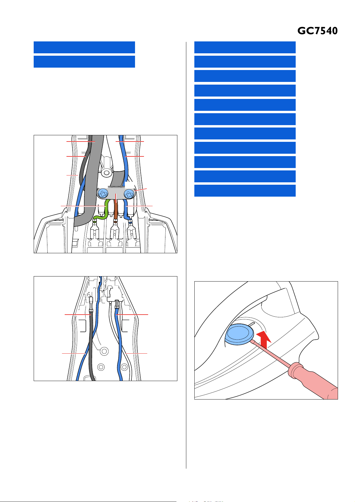
DISASSEMBLY ADVICE - IRON
GC7480
GC7540
BACKPLATE 18
HOSE CORD ASSY 19
Remove Screw A
Disassemble BACKPLATE 18
Remove Screw B1, B2
Remove Clamping plate
Remove Power cord quick-connect S, E, L, N
Disassemble Steam hose
Disassemble HOSE CORD ASSY 19
Steam hose
Black
Hose clip(a)
S
B2
B1
Brown
Power cord
N
Blue
Clamping
plate
BlueGreen
NLE
Fig 1. Wiring at rear HOUSING (Part 1)
INLAY 17
STEAM LOCK 13
LAMP MOUNTED ASSY 8
MICROSWITCH ASSY 11
TRIGGER 12
THERMOSTAT DIAL ASSY 15
HOUSING PRINTED 10
SOLEPLATE COVER 6
THERMOSTAT BUSH 9
RUBBER HOSE 3
SOLEPLATE ASSY 1
Remove Screw A
Disassemble BACKPLATE 18
Release Inlay rear catch
Disassemble INLAY 17
Disassemble STEAM LOCK 13
Disassemble MICROSWITCH ASSY 11
Remove Screw C
Disassemble TRIGGER 12
Disassemble THERMOSTAT DIAL 15
Black
(Microswitch)
Blue
(Lamp assy)
Fig 2. Wiring at rear HOUSING (Part 2)
NS
Blue
(Micro switch)
White
(Lamp assy)
Fig 3.
Remove Screws D1, D2, D3
Disassemble HOUSING PRINTED 10
Remove HOSE CLIP 4
Disassemble RUBBER HOSE 3
Remove Screws E1, E2, E3
Disassemble SOLEPLATE COVER 6
2-8
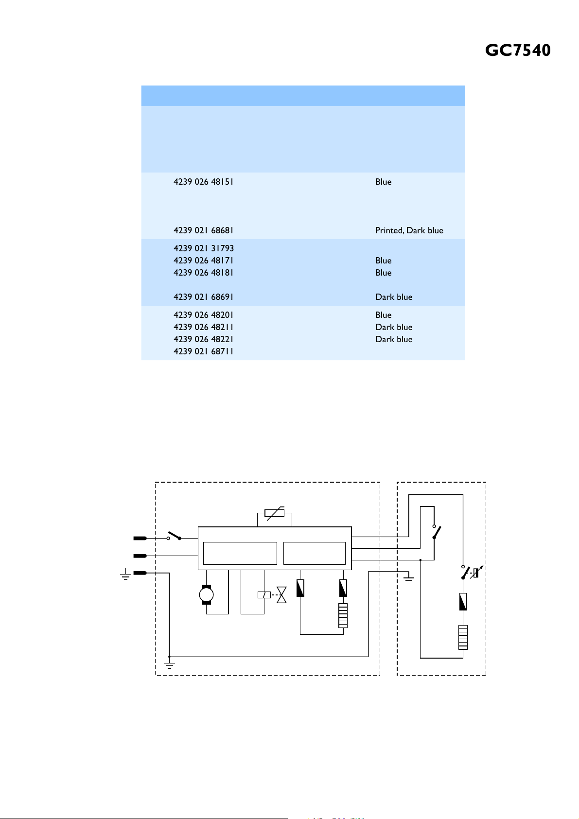
PARTS LIST - IRON & ELECTRICAL DIAGRAM
GC7480
4239 026 41811
4239 021 76801
4239 026 53531
4239 026 53541
4239 026 21895
4239 021 75532
4239 021 76811
4239 021 76601
4239 026 53511
4239 026 53521
LE Blue
Dark Blue
Dark Blue
LE Blue
Dark Blue
LE Blue
Printed
Pos Service code Description Remark
1
4239 021 68641
2
4239 015 56122
3
4239 015 56511
4
4239 010 10111
5
4239 015 70153
6
4239 026 48151
7
4239 021 31782
8
4239 021 36861
9
4239 026 13222
10
4239 021 68681
11
4239 021 31793
12
4239 026 48171
13
4239 026 48181
14
4239 010 09293
15
4239 021 68691
16
4239 026 48201
17
4239 026 48211
18
4239 026 48221
19
4239 021 68711
Soleplate assy 230 V
Rubber hose (SOS)
Rubber hose (dosing)
Hose clip
Ryton ring
Soleplate cover
Steam deviator assy
Lamp mounted assy
Thermostat bush
Housing
Microswitch assy
Trigger
Steam lock
Trigger spring
Thermostat dial assy
SOS knob
Inlay SOS
Backplate
Hose cord mounted assy
GC7540
Steamglide-SOS
Blue
Printed, Dark blue
Blue
Blue
Dark blue
Blue
Dark blue
Dark blue
Thermistor 1
Trigger
Switch
L
S
N
Thermostat
Thermal
Fuse
Heating
Element
Pump
L
On/off switch
N
Steam select switch
M
L
N
Boiler Electronics
Power LED 1x
Steam LED's 3x
Electrovalve
Thermal
Fuse
Boiler
Heating
Element
STAND IRON
Fig 4. Electrical diagram
3-8
 Loading...