

Philips FW C1 FW, FW C1 C10 Service Manual

Service
Service
FW-C1 & FW -C10
A00 - 165
Service
Product Service Group CE Audio
Service Information
Already published Service Informations: A00-161 3139 785 22440
CHANGES DURING PRODUCTION
* From production wk042 onwards, a new 3CDC-LC-MB-
DA11 is introduced. It can be recognized by:
- a new CD Drive DA11T3C and bigger Pressure Ring
- a new CD Board with 12NC 3103 303 34672 where the
last digit is the pt no of the board.
T o facilitate this changeover the µProcessor IC 7401 on the
Front Board is changed to 9965 000 06741 (OTP equivalent) and can be recognized by printing mark "C10S52631".
New CDC Module including circuits, layout diagrams and
electrical parts list are enclosed.
2000 - 11 - 13
3139 785 22680

DO NOT PRINT
------- BLANK PAGE -------

10-1
TABLE OF CONTENTS
Servicing Hints..................................................................10-2
Blockdiagram ....................................................................10-5
Component Layout Main Board ........................................10-6
Circuit Diagram part1........................................................10-7
Component Layout Main Board ........................................10-8
Circuit Diagram part2........................................................10-9
Exploded View ..................................................................10-10
Partslist .............................................................................10-12
3CDC-LC-MB-DA11 Module
(3 Disc Carousel Changer)
Layout stage .2

10-2
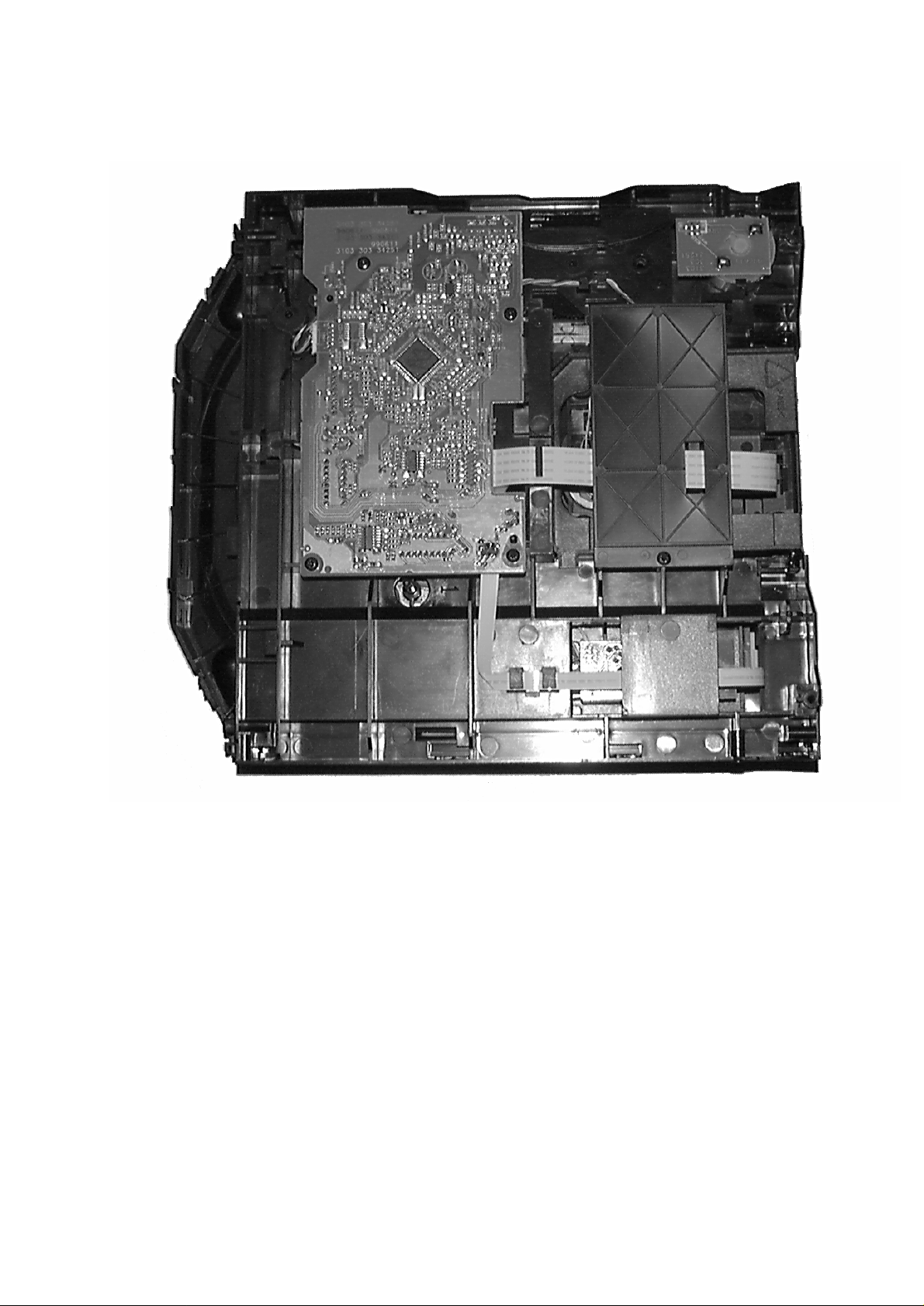
The following steps have to be done when replacing the CD mechanism:
1. Disconnect CD drive flexfoil from old CD drive
2. Connect paperclip to CD drive flexfoil to short-circuit flexfoil (fig.1)
3. Remove old CD drive
4. Remove short-circuit from flexfoil of CD drive
5. Connect flexfoil to new CD drive
6. Position new CD drive in its studs
7. Remove short-circuit from Laserunit
CHARGED CAPACITORS ON THE SERVO BOARD MAY DAMAGE THE CD DRIVE ELECTRONICS WHEN
CONNECTING A NEW CDM MECHANISM. THAT´S WHY, BESIDES THE SAFETY MEASURES LIKE
• SWITCH OFF POWER SUPPLY
• ESD PROTECTION
ADDITIONAL ACTIONS MUST BE TAKEN BY THE REPAIR TECHNICIAN.
WARNING
fig.1
Attention: The laser diode of this CD drive is protected against ESD by a solder joint which shortcircuits the
laserdiode to ground.
For proper functionality of the CD drive this solder joint must be removed after connection the drive to
the set.
CD Drive
Bottom side view
10-3
Service Position
 Loading...