


Philips Lighting North America Corporation
200 Franklin Square Drive
Somerset, NJ 08873, USA
Phone: 855-486-2216
www.philips.com/luminaires
Philips Lighting Canada Ltd.
281 Hillmount Road,
Markham ON, Canada L6C 2S3
Phone: 800-668-9008
www.philips.com/luminaires
9140053154
WARNING – Shut off AC power to branch
circuits to which units will be connected. All
wiring should be per N.E.C. Articles 501-4(b)
and local codes.
To maintain warranty, equipment with batteries
must be installed or placed on charge within
prescribed period after shipment.
Fusion III
120VAC OR 277VAC
AC ONLY OPERATION
INSTALLATION AND
OPERATING
INSTRUCTIONS
IMPORTANT
SAFEGUARDS
When using electrical equipment, basic safety
precautions should always be followed, including
the following:
READ AND FOLLOW ALL
SAFETY INSTRUCTIONS
All servicing should be performed by qualified
personnel only.
Equipment should be mounted in locations and at
heights where it will not be readily subjected to
tampering by unauthorized personnel.
The use of accessory equipment not recommended
by the manufacturer may cause an unsafe condition.
Do not use this equipment for other than intended
use.
Do not let supply cords touch hot surfaces.
Do not mount near gas or electric heaters.
Caution: Halogen cycle lamp(s) are used in this
equipment. To avoid shattering: Do not operate
lamp in excess of rated voltage, protect lamp
against abrasion and scratches and against liquids
when lamp is operating, dispose of lamp with care.
Halogen cycle lamps operate at high temperatures.
Do not store or place flammable materials near
lamp.
Use caution when servicing batteries. Battery acid
can cause burns to skin and eyes. If acid is spilled
on skin or eyes, flush acid with fresh water and
contact a physician immediately.
CAUTION: To avoid electrical overload, total
connected lamp load (factory and field installed)
should not exceed output rating.
SAVE THESE
INSTRUCTIONS
Philips Lighting North America Corporation
200 Franklin Square Drive
Somerset, NJ 08873, USA
Phone: 855-486-2216
www.philips.com/luminaires
Philips Lighting Canada Ltd.
281 Hillmount Road,
Markham ON, Canada L6C 2S3
Phone: 800-668-9008
www.philips.com/luminaires
9140053154
STEP 1
Remove cover assembly by pulling straight off of housing assembly (there are two spring clips
that hold them together). Set cover assembly aside.
GENERAL INSTRUCTIONS

Philips Lighting North America Corporation
200 Franklin Square Drive
Somerset, NJ 08873, USA
Phone: 855-486-2216
www.philips.com/luminaires
Philips Lighting Canada Ltd.
281 Hillmount Road,
Markham ON, Canada L6C 2S3
Phone: 800-668-9008
www.philips.com/luminaires
9140053154
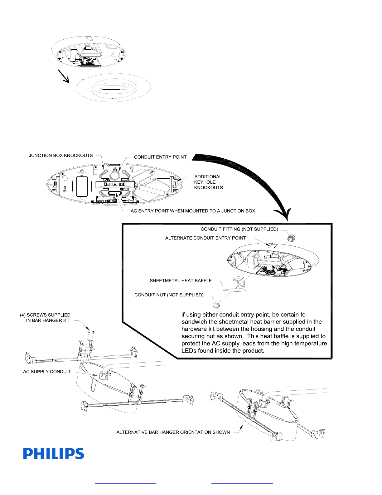
STEP 2
For surface mounting, a knockout pattern is supplied for 3-1/2” octagonal or single gang junction
boxes. Remove desired mounting knockouts and the rectangular knockout found in the lower center area
of the housing. The rectangular knockout will allow for AC supply entry. (The LED’s may be seen to
flash while striking the knockouts for removal. The battery may be temporarily disconnected to
eliminate this if desired).
For recessed mounting, the packaging insert also functions as a template for cutting the correct
size and shape opening in the mounting surface. A bar hanger kit is supplied. The bar hangers may be
mounted to the housing assembly in either orientation shown depending upon desired mounting. A
round conduit entry knockout is provided in the upper center or side of the housing.
STEP 3
Make AC supply connections. The input may be connected to either switched or unswitched
AC service. Cap off unused 120VAC or 277VAC wire to prevent shorting.
STEP 4
Reinstall cover assembly.
 Loading...