

Philips 32PF7320/93, 32PF5320 - 5, 32PF7320 - 5, 26PF5320, 32PF5320 Quick Use Manual
...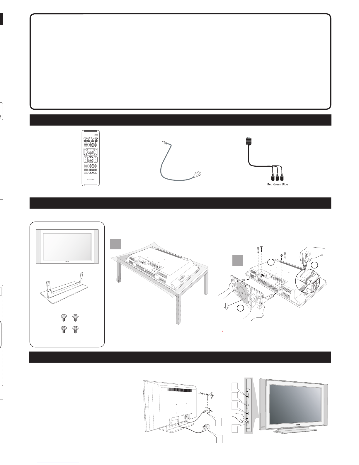
LISTING THE ACCESSORIES
First, assemble the LCD TV using the steps below:
Gently pull out the stand arm cover to locate all the sockets at the
bottom of the set.
1
Connect the aerial cable (not supplied) from the aerial
socketof the TV to the wall socket.
2
Connect the mains cord to the television power inlet and the
mains plug into the wall socket.
3
Press the POWER button at the side of the TV set to switch
to turn on the TV.
4
Press the VOLUME + button to increase the sound level or
the decrease the VOLUME - button to lower the sound level.
5
Press the PROGRAM + or - button to select the TV
programmes.
6
Press the MENU button to display the on-screen menu. Use
the VOLUME and PROGRAM buttons for selection and
adjustments in the on-screen menu.
1
2
5
6
4
3
A
B
C
x 1
x 1
x 4
LCD TV STAND ASSEMBLY
TV mains cord (two-pin) x 1 Remote Control x 1
VGA socket (DB-15) to cinch x 1
BASIC LCD TV OPERATION
LCD TV
Quick Use Guide
Thank you for purchasing Philips LCD Television set. You are now the proud owner of
a LCD TV set which promises full value to you as a customer. This Quick Use Guide is
designed to help you to do the connections to install and operate your TV. We strongly
recommend you to read the instructions thoroughly.
26PF5320
32PF5320
32PF7320
1
2
3141 045 20061
Jack Panel Bottom of TV
The audio/video input jacks on the bottom panel of the TV are for
direct picture and sound connections between the TV and a VCR (or
similar device) that has audio/video output jacks.
1
Using an RCA type Video Cable, connect one end of the cable to
the Video (yellow) Out jack on the VCR or accessory device and
the other end to the AV Video In jack on the bottom of the TV.
2
Using an RCA type Audio Left and Right Cable, connect one end
to the left and right Audio Out L & R jacks (red & white) on the
VCR or accessory device and the other ends to the AV Audio In
L & R jacks on the bottom of the TV.
3
Turn the VCR or accessory device and the TV On.
4
Press the AV button on the remote control to show the Source
List menu on the TV screen.
5
Press the œ button repeatedly until AV is highlighted, then press
the π button to enter the selected Mode.
6
With the VCR (or accessory device) ON and a prerecorded
tape (CD, DVD, etc.) inserted, press the PLAY button to view
the tape on the television.
COMPONENT VIDEO INPUTS (CVI)
2
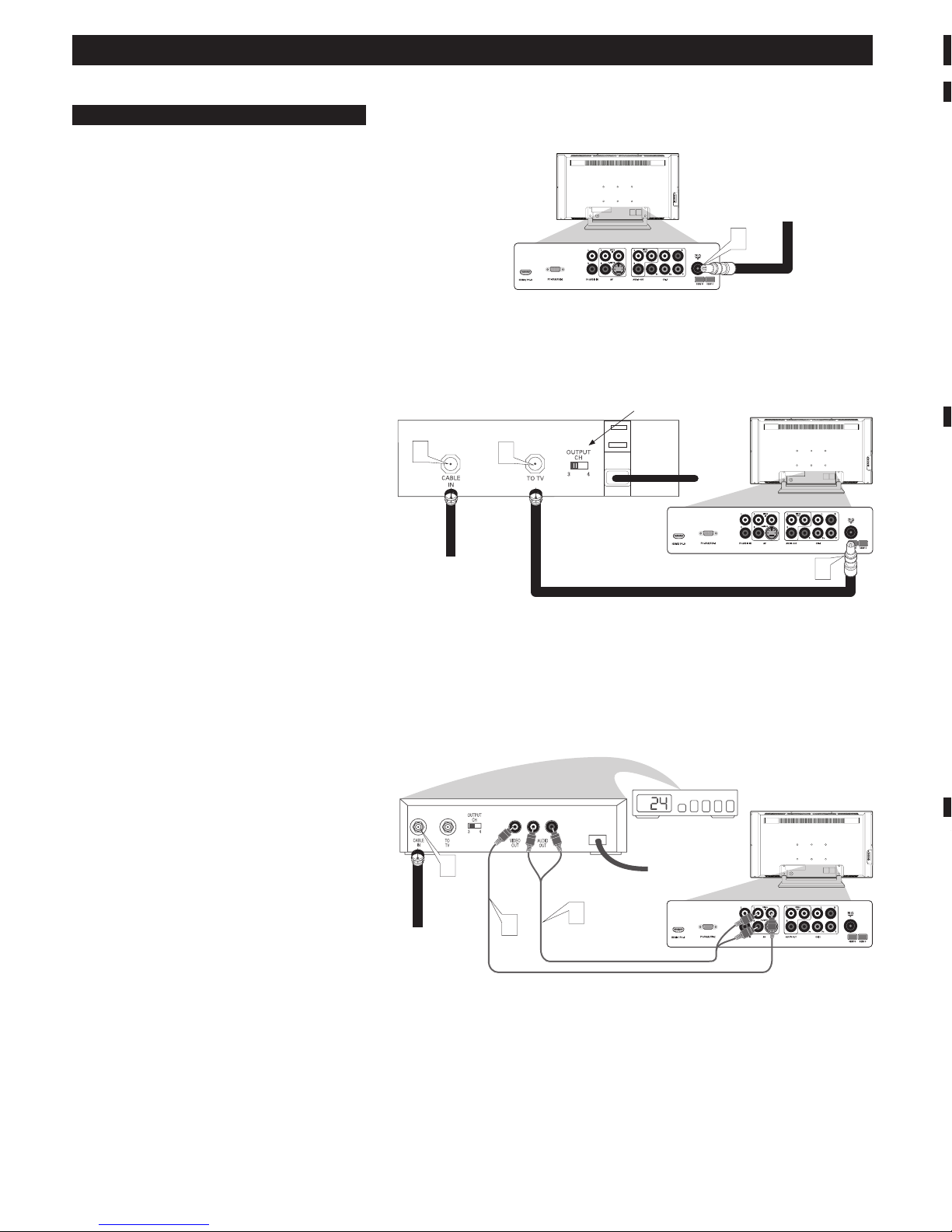
CABLE/CABLE BOX TV
Your Cable TV input into your home may be a single (75 ohm) cable
or use a cable box decoder. In either case the connection is very
simple. Follow the steps below to connect your cable signal to your
new television.
Direct Cable Connections:
This connection will supply Stereo sound to the TV.
1
Connect the open end of the round Cable Company supplied
cable to the 75Ω input on the bottom of the TV.
Cable Box (w/RF In/Outputs):
This connection will NOT supply Stereo sound to the TV. The sound
from the cable box will be mono.
1
Connect the open end of the round Cable Company supplied
cable to the cable signal IN(put) plug on the back of the Cable
Box.
2
Using a separate round coaxial cable, connect one end to the
OUT(put) (TO TV) plug on the back of the Cable Box.
3
Connect the other end of the round coaxial cable to the 75Ω
input on the bottom of the television.
NOTE: Be sure to set the OUTPUT CHANNEL SWITCH on the
back of the cable box to CH 3 or 4, then tune the cable box on the
TV to the corresponding channel. Once tuned, change channels at
the cable box, not the television.
Cable Box (w/Audio/Video Outputs):
This connection will supply Stereo sound to the TV.
1
Connect the open end of the round Cable Company supplied
cable to the cable signal IN(put) plug on the back of the Cable
Box.
2
Using an RCA type Video Cable, connect one end of the cable
to the Video (yellow) (or ANT, your cable box may be labeled
differently) Out jack on the cable box and the other end to the
Video In jack on the bottom of the TV.
3
Using an RCA type Audio Left and Right Cable, connect one end
to the left and right Audio Out L & R jacks (red & white) on the
cable box and the other ends to the Audio In L & R jacks on the
bottom of the TV.
NOTE: Use the AV button and the CURSOR DOWN/RIGHT
on the TV remote control to tune to the AV channel for the cable
box signal. Once tuned, change channels at the cable box, not the
television.
Component Video inputs provide the highest possible color and
picture resolution in the playback of digital signal source material,
such as with DVD players.
1
Connect the Component (Y, Pb, Pr) Video OUT jacks from the
DVD player (or similar device) to the CVI-1 VIDEO Input (Y
green, Pb blue, Pr red) jacks on the bottom of the TV.
2
Connect the red and white AUDIO CABLES to the Audio (left
and right) output jacks on the rear of the accessory device to the
CVI-1 Audio In L & R jacks on the bottom of the TV.
3
Turn the TV and the DVD player (or digital accessory device)
ON.
4
Press the AV button on the remote control to show the Source
List menu on the TV screen.
5
Press the œ button repeatedly until CVI-1 is highlighted, then
press the π button to enter the selected Mode.
6
Insert a DVD disc into the DVD player and press the PLAY
button on the DVD Player.
HD (HIGH DEFINITION) INPUTS
If you are using a High Defi nition receiver that can transmit high
defi nition programming, the TV can except those signals through the
HD Inputs located on the bottom of the TV.
1
For Digital Connection, connect the HDMI connector of the
HD Receiver (or similar device) to the HDMI Input jacks on the
bottom of the TV.
OR
For Analog Connection, use Component Video cables to con-
nect the Component (Y, Pb, Pr) Video Out jacks of the HD
Receiver (or similar device) to the VGA adapter (supplied with
the TV). Connect the other end of the adapter to the VGA Input
jacks (CVI-2) on the bottom of the TV.
2
Connect the red and white audio cable to RCA type Audio
Cables. Connect the audio adapter to the PC Audio In L & R
jacks on the bottom of the TV.
3
Turn the TV and the HD Receiver ON.
4
Press the AV button on the remote control to show the Source
List menu on the TV screen.
5
Press the œ button repeatedly until HDMI or CVI-2 (SD/HD) is
highlighted, then press the
Direct Cable Connection:
Cable signal coming from
Cable Company (Round
75Ω coaxial cable)
Jack Panel Bottom of TV
Cable Box with RF Inputs and Outputs Connection:
Jack Panel Back
of Cable Box
Cable Box with Audio/Video Outputs Connection:
Cable Signal IN
from the Cable
Company
Audio Cables L & R
(Red, White)
1
Jack Panel Bottom of TV
Cable Signal IN from
the Cable Company
Output Channel Switch
Round 75Ω
Coaxial Cable
1
3
2
Jack Panel Back of Cable
Box with A/V Outputs
Video Cable (Yellow)
1
3
2
CONNECTING PERIPHERAL EQUIPMENT TO THE LCD TELEVISION
 Loading...