

Page 1

uick Start Setup Guide
S
2HFL4663
Page 2

Know these safety symbols
.philip
s
t
CAUTION
RISK OF ELECTRIC SHOCK
DO NOT OPEN
CAUTION: TO REDUCE THE RISK OF ELECTRIC SHOCK, DO NOT
REMOVE COVER (OR BACK). NO USER-SERVICEABLE PARTS
INSIDE. REFER SERVICING TO QUALIFIED SERVICE PERSONNEL.
The caution marking is located on the rear or bottom of the cabinet.
The lightning flash with arrowhead symbol, within an equilateral
triangle, is intended to alert the user to the presence of
uninsulated “dangerous voltage” within the apparatus’s enclosure
that may be of sufficient magnitude to constitute a risk of
electric shock to persons.
The exclamation point within an equilateral triangle is intended to
alert the user to the presence of important operating and
maintenance (servicing) instructions in the literature accompanying
the apparatus.
WARNING: To reduce the risk of fire or electric shock, do not expose this apparatus to rain or moisture. Apparatus shall
CAUTION: To prevent electric shock, match wide blade of plug to wide slot, fully insert.
ATTENTION
not be exposed to dripping or splashing and no objects filled with liquids, such as vases, shall be placed on the
apparatus.
: Pour éviter les choc électriques,introduire la lame la plus large de la fiche dans la borne correspondante de la
prise et pousser jusqu’au fond.
Visit our World Wide Web Site at www.philips.com/support
www.philips.com/hospitality
.com/suppor
Page 3
Important Safety Instructions
.
.
.
.
.
.
g
.
g
t
.
.
t
.
l
illed
lly
d.
T
t
.
A
A
E
Q
P
Wall M
t
V
s
l
T
.
.
he B
.
The Wall M
.
ll.
.
injury.
Wall M
.
hile y
l
y.
Wh
T
)
)
)
. Read these instructions
2. Keep these instructions
. Heed all warnings
4. Follow all instructions
. Do not use this apparatus near water.
. Clean only with dry cloth
. Do not block any ventilation openings. Install in
accordance with the manufacturer’s instructions
8. Do not install near any heat sources such as radiators,
heat registers, stoves, or other apparatus (includin
amplifi ers) that produce heat
9. Do not defeat the safety purpose of the polarized or
grounding-type plug. A polarized plug has two blades
with one wider than the other. A grounding type plu
as two blades and a third grounding prong. The wide
blade or the third prong are provided for your safety. If
he provided plug does not fi t into your outlet, consult
an electrician for replacement of the obsolete outlet
0. Protect the power cord from being walked on or
pinched particularly at plugs, convenience receptacles,
and the point where they exit from the apparatus
1. Only use attachments / accessories specifi ed by the
manufacturer.
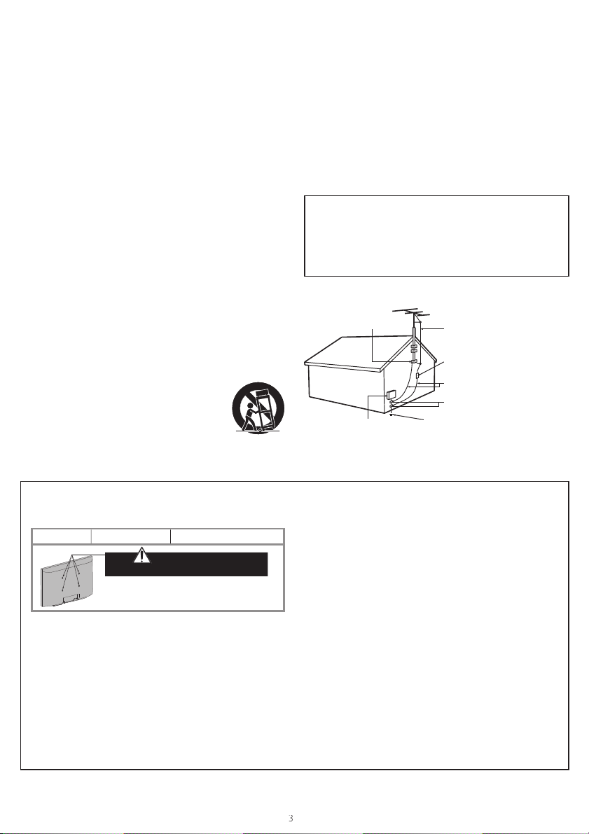
2. Use only with the cart, stand, tripod, bracket, or
able specifi ed by the manufacturer, or
sold with the apparatus. When a cart
s used, use caution when moving the
art / apparatus combination to avoid
njury from tip-over.
3. Unplug this apparatus during lightning storms or when
nused for long periods of time
4. Refer all servicing to qualifi ed service personnel.
ervicing is required when the apparatus has been
amaged in any way, such as power-supply cord or
p
ug is damaged, liquid has been sp
or objects
ave fallen into the apparatus, the apparatus has
een exposed to rain or moisture, does not operate
orma
, or has been droppe
Note to the CATV system installer:
his reminder is provided to call the CATV system installer’s
attention to Article 820-40 of the NEC that provides guidelines for
proper grounding and, in particular, specifies that the cable ground
hall be connected to the grounding system of the building, as close
o the point of cable entry as practical
Example of Antenna Grounding as per NEC - National
Electric Code
ROUND CLAM
ELECTRIC SERVICE E
UIPMENT
NTENNA LEAD IN WIR
NTENNA DISCHARGE UNIT
NEC SECTION 810-20)
ROUNDING CONDUCTORS
NEC SECTION 810-21)
ROUND CLAMPS
OWER SERVICE GROUNDING ELECTRODE
SYSTEM (NEC ART 250, PART H)
Brand: SANUS
2HFL4663S
ount Bracket Ki
Model # Screw dimension
M200
packed with Wall Mount Bracket Kit.
For 32 inch TVs, you need to purchase screws
y with dimensions described below.
separate
he recommended Wall Mount Bracket Kit (sold
separately) allows the mounting of the TV on the wall
or detailed information on installing the wall mount,
refer to the Wall Mount Instruction Book
&F USA is not responsible for any damage to the
roduct or injury to yourself or others if you elect to
nstall the TV Wall Mount Bracket or mount the TV
onto t
racket on your own
ount Bracket must be installed by experts
M4 x 0.472” (12mm)
Do NOT use screws
&F USA is not liable for these types of accidents or
injury noted below.
nstall the Wall Mount Bracket on a sturdy vertical wa
If installed onto a ceiling or slanted wall, the TV and Wall
Mount Bracket may fall which could result in a severe injury.
o not use screws that are longer or shorter than their
specifi ed length. If screws too long are used this may cause
mechanical or electrical damage inside the TV set. If screws
too short are used this may cause the TV set to fall
Do not fasten the screws by excessive force. This may
amage the product or cause the product to fall, leading
to an
or safety reasons use 2 people to mount the TV onto a
ounting Bracket
o not mount the TV onto the Wall Mounting Bracket
w
our TV is plugged in or turned on. It may result in
an e
ectrical shock injur
en installing the unit on the wall, allow this much space.
op: 11.8 inches30cm
Left and right side: 5.9 inches15cm
ottom: 3.9 inches(10cm
Page 4

4
1 Notice
T
thei
bliged
.
T
y
purp
y
t
y
.
ible.
s
T
.
W
y
t
w
plied.
A
bl
hall
.
f
Th
g
lled
,
t
t
.
iver
.
t
.
Trade N
S
.
A
.
Teleph
s
T
.
s
p
.
t
A
thei
.
Th
HDMI
HDMI High
,
the HDMI L
g
h
.
lby
D
.
T
.
t
.
®
Ag
lping
d
gh
.
T
t
.
®
.
f
rademarks are the proper ty of Koninklijke Philips Electronics N.V. or
r respective owners.
&F USA reserves the right to change products at any time without
eing o
he material in this manual is believed adequate for the intended use
of the s
are used for
of their validit
hat the material itself does not infringe any United States patents. No
further warrant
&F USA cannot be held responsible neither for any errors in the
content of this document nor for any problems as a result of the
content in this document. Errors reported to P&F USA will be
adapted and published on the P&F USA support website as soon as
poss
ixel characteristic
his LCD product has a high number of color pixels. Although it has
effective pixels of 99.999% or more, black dots or bright points of light
(red, green or blue) may appear constantly on the screen. This is a
structural proper ty of the display (within common industry standards)
and is not a malfunction
o components are user serviceable. Do not open or remove covers
o the inside of the product. Repairs may only be done by Service
enters and offi cial repair shops. Failure to do so shall void any
arranty, stated or im
ny operation expressly prohibited in this manual, any adjustments or
assem
s
Federal Communications Commission Notice
This equipment has been tested and found to comply with the limits
or a Class B digital device, pursuant to part 15 of the FCC Rules.
harmful interference in a residential installation. This equipment
enerates, uses and can radiate radio frequency energy and, if not
insta
harmful interference to radio communications. However
is no guarantee that interference will not occur in a particular
installation. If this equipment does cause harmful interference to
adio or television reception, which can be determined by turning
he equipment off and on, the user is encouraged to try to correct
he interference by one or more of the following measures:
Declaration of Conformity
esponsible Party :
odel :
ddress :
to adjust earlier supplies accordingly
stem. If the product or its individual modules or procedures
oses other than those specifi ed herein, confi rmation
and suitability must be obtained. P&F USA warrants
is expressed or implied
arrant
y procedures not recommended or authorized in this manual
void the warranty
ese limits are designed to provide reasonable protection against
and used in accordance with the instructions, may cause
eorient or relocate the receiving antenna
ncrease the separation between the equipment and the
.
rece
onnect the equipment into an outlet on a circuit different
from that to which the receiver is connected
onsult the dealer or an experienced radio or television
echnician for help
ame :
one Number :
HILIP
&F USA, Inc
2HFL4663S
O Box 430, Daleville, IN 47334-0430 U.S.A
866 497 4225
there
Modifi cation
his apparatus may generate or use radio frequency energy. Changes
r modifi cations to this apparatus may cause harmful interference
nless the modifi cations are expressly approved in the manual. The
ser could lose the authority to operate this apparatus if an
nauthorized change or modifi cation is made
able
onnections to this device must be made with shielded cables with
metallic RFI / EMI connector hoods to maintain com
ules and Regulations
liance with FCC
anadian notice
This Class B digital apparatus complies with Canadian ICES-003.
tandard Television Receiving Apparatus, Canada BETS-7 / NTMR-7.
opyrigh
ll other registered and unregistered trademarks are the proper ty of
r respective owners
e terms
Defi nition Multimedia Interface
or registered trademarks of HDMI
Licensin
ot
er countries
aboratories. Do
symbol are trademarks of Dolby
onsumer Notice:
his TV has been set to maximize energy effi ciency while delivering
he best possible picture using the factory installed home mode
ettings
hanging or enabling other features in this TV (e.g. br ightened
acklighting) will possibly increase energy consumption beyond the
ortions of this software are copyright © The FreeType Project
www.freetype.org).
The American Academy of Pediatrics discourages television viewing
or children younger than two years of age.
aboratories
ruSurround XT technology is
ncorporated under license from SRS
abs, Inc
RS TruSurround XT® creates a truly
mmersive surround sound experience
with rich bass and clear dialog from only
wo speakers
of the U.S. Environmental Protection
ency and the U.S. Department of
nergy he
rotect the environment throu
energy effi cient products and practices
qualifi ed limits
and
ogo are trademarks
LLC in the United States and
and the double-
is a joint program
us all save money an
and
-
Page 5

2 Important
TV.
y
.
ition.
ib
.
temp
g
.
.
.
t
t
.
.
.
.
A
f
Th
a book
a
to turn the unit on and go into standby mode.
d
:
he lik
:
T
a
T
T
th
.
l
s
w
.
s
The b
and
Positioning the TV
Environmental care
Large screen TVs are heavy. 2 people are required to carry and
andle a large screen
Make sure to hold the upper and bottom frames of the unit
as illustrated
fi rml
nstall the unit in a horizontal and stable
pos
o not install the unit in direct sunlight
r in a place subject to dust or strong
ration
v
epending on the environment, the
erature of this unit may increase
htly. This is not a malfunction
sli
Avoid a place with drastic temperature changes
Do not place anything directly on top or bottom of the unit
Depending on your external devices, noise or disturbance of
he picture and / or sound may be generated if the unit is placed
oo close to them. In this case, please ensure enough space
etween the external devices and the unit
Do not insert the AC power cord into the power socket outlet
before all the connections are made
Ensure that you always have easy access to the AC power cord
r plug to disconnect the TV from the power.
Before you move the TV, disconnect attached cables to prevent
amage to connectors
Be sure to unplug the AC power cord from the AC outlet
before moving or carrying the unit
Regulatory notices
Do not place the unit on the furniture that is capable of being tilted
by a child and an adult leaning, pulling, standing or climbing on it.
alling unit can cause serious injury or even death.
is apparatus should not be placed in a built-in installation such as
case or rack unless proper ventilation is provided.
Make sure to leave a space of 4 inches (10cm) or more around this
pparatus.
ress
To completely turn off the unit, you must unplug the AC power
cor
.
Disconnect the AC plug to shut the unit off when trouble is found
or not in use. The AC plug shall remain readily available.
ever use a gas duster on this TV.
The gas trapped inside of this unit may cause ignition and explosion.
AUTION:Danger of explosion if battery is incorrectly replaced.
WARNING
WARNING
eplace only with the same or equivalent type.
Batteries (battery pack or battery installed) shall not
be exposed to excessive heat such as sunshine, fi re
or t
e.
o prevent injury, this apparatus must be securely
ttached to the furniture / wall in accordance with the
instructions.
cause injury / death.
ipping, shaking or rocking the unit may
he packaging of this product is intended to be recycled.
ontact your local authorities for information about how to recycle
e packaging
or product recycling information, please visit -
www.recyc
e.philips.com
End of life directive
Philips pays a lot of attention to produce environment-friendly
products in green focal areas. Your new TV contains materials
hich can be recycled and reused. At the end of its life, specialized
ompanies can dismantle the discarded TV to concentrate the
reusable materials and to minimize the amount of materials to be
isposed of. Please ensure you dispose of your old TV according to
ocal regulations
Disposal of used batterie
atteries supplied do not contain the heavy metals mercury
cadmium. Nevertheless, in many areas batteries may not be
isposed of with your household waste. Please ensure you dispose
of batteries according to local regulations.
Page 6

How to use this guide
T
ibl
.
th
T
g
:
s
A
t
the ill
.
T
:
TV
TV
d
W
l
s
TV
)
TV
)
The i
ly.
A
Phili
l.
t
t
T
A
w
t
.
Th
the ill
.
he Quick Start Setup Guide helps you install the Philips
ommercial television, as quickly as poss
e. It contains the
necessary information to install the TV and confi gure the
settings. Read and understand the instructions in the Quick
tart Setup Guide before you use your TV
or detailed information on additional features, download
e user manual by selecting your TV model at
www.philips.com/hospitality.
he Quick Start Setup Guide contains the followin
nformation
ontents of the box
onfi guration of channel and advanced setting
loning of data
s part of striving to improve the TV performance
hroughout the product life, some TV menus may differ from
ustration on this document
The contents of the box
he box contains the following items
TV Setup
hilips Hospitality TVs have a USB cloning capability so you
nly need to manually setup one TV - the “master TV”. Then
he complete setup confi guration can be copied from the
master TV to a USB storage device which can then be used
o load the same setup confi guration into all other TVs.
tep 1 is to setup the master TV as follows:
Accessing the setup menu
o access and adjust the setup functions, YOU MUST USE
SPECIAL SETUP REMOTE CONTROL (not provided
ith the TV) IN THE RC5 SETUP MODE. All the following
nstructions assume the use of a setup remote control in
he RC5 Setup mode
Note
e optional setup remote control is not included in the box.
ontact your Philips authorized agent or dealer to purchase the
etup remote control. Setup remote control might differ from
ustration
stan
uick Start Setup Guide (this document)
arranty sheet
emote contro
2 x AAA, 1.5V batterie
able management tie
stand hardware
tand-to-TV screws (x 3
tand pin (x 2)
crew for Stand pin (x 4)
security package
tand-to-TV security hex screws (x 3)
ecurity bolt and cap (x 2)
Washer (x 2
ecurity nut (x 2)
ecurity double-sided tape (x 4)
Note
tems are available on selected models on
n optional security tool is required to tighten the security
screws and nuts. Please contact your
stributor to purchase the too
ps authorized agent or
A B C D
E
F G RESET/UPGRADE
RECALL/INFO
HOME
BACK/PP
MENU
ALARM/CLOCK
TELETEXT
MUTE
TV
VOL
ABC DEF
JKL MNOGHI
TUV WXYZPQRS
AV
RC5 GUEST
RC5 SETUP RC6 GUEST RC6 SETUP
HOSPITALITY
GUIDE
OPTIONS
SMART
CC
P
SLEEP
Page 7

7
Channel installation
Thi
ically.
.
.
T
.
at the
l.
to put the remote control into setup
t
ill b
)
p
A
t
A
A
!
s section describes how to install the TV channels
automat
onnect the RF signal to the TV
ug the power cord into the power outlet
2
ANT. IN
Cable
ANT. IN
mode, then press the HOME/MENUbutton to display
he setup menu. (Hereafter, HOME/MENU w
e
simply referred to as
elect
onsumer TV setup
Setu
utoprogram
hen select Cable. (unless the installation is using only
ntenna signals - in which case you would select
ntenna)
Note
The TV will not tune any channel that has not been fi rst
“installed”. This includes SPI direct tune commands
urn the TV on
ress
(OWER) on the remote contro
ress
4
front of the TV or use the
Cable
Page 8

f
a
b
k
c
O
d
s
e
f
g
h
A
i
g
a
b
c
d
e
DATA (RJ-12 SPI port)
Digital audio output jac
Component / Composite (VIDEO) Video Input jacks for VIDE
Analog audio (L/R) Input jack
HDMI Input jack(s)
C Input jack
USB terminal
ntenna Input jack
Headphone 3.5mm stereo jack for personal listening
DATA
h
i
8
Page 9

9
Confi gure the Switch on settings
s
vol
.
vol
th
.
l
.
ided
d.
T
s
)
s
d
l.
TV k
d
.
Th
.
Th
y.
A
A
.
Wh
TV.
T
ill displ
d.
.
t
.
.
.
idle.
t
i
ll
.
n
t
.
t
.
k
.
C
.
l
s
A
ress
ress
2
K.
and select Switch on setting
or
to select the desired mode, then press
Confi gure the Control settings
ress
ress
2
and select
or
to select the desired mode, then press
ontrol setting
Switch on
ume
aximum
ume
Switch on
channe
ower on
Defi nes the pre-set volume level when TV is powered
on
Defi nes the maximum limit of volume level except for
e external set top box
Defi nes the power-on channel number or external
video input
Determines the state of the TV when the AC power is
or restore
prov
owers on TV after the AC power is restored.
n
(digital signage application)
V enters standby mode. (hospitality)
Standby
ast
Returns TV to the same state as before
statu
ower was interrupted. (general use
TV RC
coPower
Standby
playbac
MultiR
ets the TV operative or inoperative by guest remote
contro
ocke
ets the TV operative or inoperative by local keyboard
e control buttons on the TV are disabled
n
except for the Power button
e control buttons on the TV are enabled
ff
and function normall
ll the control buttons on the TV are disabled
ll
ncluding the Power button
Enable or disable to display the “On Screen Display”.
en you select
splayed on
- channel number / label / name
- “channel not valid” information
he rest of menus such as CC, Guest menu, Setup
Menu, Status Menu, Splash Screen, Sleep Timer, Sleep
warning Message, Freeze, Child lock Message and USB
edia Playback menu, etc. are st
ets the TV to reduce the power consumption
hoose the SPI port connected to the external set
top box
ff
V3
hoose the standby mode when the TV goes into the
standby mode. When
Standby mode should be set to
the relevant SPI Port commands
ree
as
Enable or disable to support the feature of the USB
media playback. The USB cloning feature is always
enabled, regardless of this setting
Enables control of multiple TVs in a room without any
nterference from each other’s remote control
ff, those settings below cannot be
PI Port is disabled
PI Port is enabled with the data and clock
ine being pulled high to 3.3V voltage idle
PI Port is enabled with the data and clock
ne being pulled high to 5V voltage
PI Por
While the TV is turned off in this mode, the
PI functionality is limited. Once turned on,
complete SPI functionality is restored. Refer
o the full User Manual for more complete
nformation
While the TV is turned off in this mode,
complete SPI functionality is maintained
ocke
SD
isplay
PI Por
mode
SB
eys
aye
s switched to
astto support a
V3 or
Note
Supported USB Playback formats:
JPEG>
Upper limit : 24Mpixe
Motion JPEG>
ize : 320 x 240 (QVGA)
rame rate : 30fp
udio type : LPCM - Sampling frequency
(32 kHz, 44.1 kHz or 48 kHz)
- Quantization bit rate (16 bit)
Page 10

Changing picture and sound settings
Y
w
.
to enter the setting.
Adj
y.
Y
th
l
T
.
g.
s
V
.
.
.
.
d
hligh
t
Adj
.
Y
th
l
T
.
.
.
d.
.
.
t
T
p
.
T
g
.
.
to start the copy of the confi guration data to
.
.
to start the copy of the confi guration data to
TV.
A
y.
.
T
.
.
.
ÍÆ
]
ÍÆ
]
ÍÆ
]
T
lor
h
.
T
T
l
.
ou must set
ill not be memorized after the unit goes to standby mode
Changing picture settings
2
press
Auto Picture
ou can manually set the picture controls for the Personal
setting and/or you can select one of the following Auto
cture presets. Press
en press
ersona
Standardor normal TV viewin
Sport
ovie Brilliant picture settings for a cinematic experience
ame Optimized for PCs, games consoles and playstations
4
Changing sound settings
2
o select the setting.
Auto Sound
ou can manually set the sound controls for the Personal
setting and/or you can select one of the following Auto
ound presets. Press
en press
ersona
Standardor normal TV viewing
ovie Realistic sound settings for a cinematic experience
usic
ewslear sound settings for human voice
omein
ocation. Otherwise, these settings
ress
ress
ress
ress
ress
ress
; na vigate to
or
to select one of the picture settings, and
ust the picture qualit
he customized settings you defi ned by using the
icture menu
ivid picture settings for high action
to exit
; na vigate to
or
to hig
ust the following items
he customized settings you defi ned by using the
Sound menu
Emphasize high and low frequency for instrument
soun
to exit
onsumer TV setup -icture
or
to select the desired setting,
onsumer TV setup- Soun
t a sound setting and press
or
to select the desired setting,
Clone TV confi guration data
Once you have completed the setup of the master TV and
ested that it receives all the required channels, follow the
V to USB section below to extract a copy of the setu
confi guration to a USB storage device
hen follow the USB to TV section below to copy the
setup confi guration to all additional TVs using the same
uration
confi
TV to USB
onnect your USB storage device to the USB port on
the side of your TV
ress
ress
USB
and select TV to USB
USB to TV
onnect your USB storage device to the USB port on
the side of your TV
ress
2
ress
Note
fter this setting is completed, the TV will restar t automaticall
and select USB to TV
Multi RC
Multi RC enables control of multiple TVs in a room without any
nterference from each other’s remote control
o enable Multi RC, each remote control is set to one of the
four colors - Blue, Green, Yellow or Red. Each TV in the room
s separately programmed to a remote control of one of those
olors
In this way, each TV responds to only one RC that is set to the
ame color as the TV itself. This prevents interference from each
ther’s remote control when you watch multiple TVs in a room
ress
setup menu
ress
2
ress
ress
he TV is confi gured to respond to the RC that is set to the
same co
n the guest RC, press HOME (the menu button) and
e color button (same color as above) simultaneously,
t
for at least 5 seconds
he guest RC is set to the selected color.
Note
he Guest RC defaults to Blue, and a remote which has been
set to any co
confi gured to a different color yet. Therefore, if 2 TVs are being
confi gured in the same space, then each TV/RC pair MUST
be set a their own color (one pair cannot be left as default,
otherwise both RCs will operate the TV which has not been
confi gured)
on the setup remote control to display the
Îï
to select
Îï
to select
Îï
to select
.
or can operate any TV which has not been
Control settings
MultiRC
Select a color code
0
Page 11

Page 12

.
PO Box 430 Daleville, IN 47334-0430
.
A
,
A
H
P&F USA, Inc
v. La Palma No. 6, Col. San Fernando La Herradura
&F Mexicana, S.A. de C.V
Huixquilucan Edo. de México C.P. 52787
hilips and Philips Shield are used under license of
oninklijke Philips Electronics N.V.
rinted in
hina
21FZU
EMN29461A
 Loading...