

Page 1
T13.01.000.0000.0003
2019/04 Revision Index E
English
Operating Instructions
Assembly Instructions
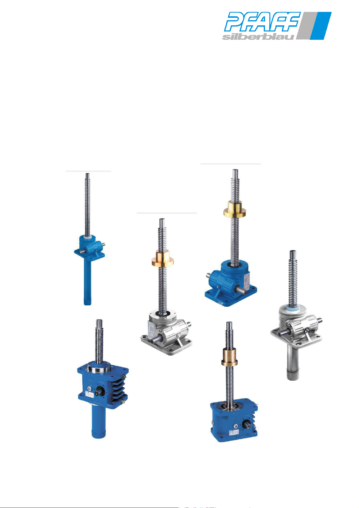
Worm gear screw jacks type 1 and type 2
SHE BG0,5 – BG 200.1
HSE 32 –HSE 140
Columbus McKinnon Engineered Products GmbH
Am Silberpark 2-8
D-86438 Kissing
Telefon: +49(0)8233 2121 800
Telefax: +49(0)8233 2121 805
Page 2

GB
Worm gear screw jack SHE type1 and type2
High-performance screw jack HSE type1 and type2
T13.01.000.0000.0003
2019/04 Rev. Index E
1 Intended use ............................................................................................................................ 4
1.1 Screw jacks with safety devices for lifting platforms ...................................................... 4
1.2 Worm gear screw jacks in accordance with ATEX guideline 2014/34/EC..................... 4
2 Accident prevention guide ..................................................................................................... 5
3 Safety information ................................................................................................................... 6
3.1 General safety information ............................................................................................. 6
3.2 ATEX safety information ................................................................................................ 6
3.3 Type plate ...................................................................................................................... 6
4 Technical specifications ......................................................................................................... 7
4.1 High-performance worm gear screw jacks HSE, standard and with safety features ..... 7
4.2 Worm gear screw jack SHE standards and with safety features ................................... 8
4.3 Technical specifications ATEX ...................................................................................... 9
5 Receipt of goods, storage, transport .................................................................................... 10
5.1 Receipt of goods ............................................................................................................ 10
5.2 Transport ........................................................................................................................ 10
5.3 Storage .......................................................................................................................... 10
6 Worm gear screw jacks, standard version ........................................................................... 11
6.1 Safety worm gear screw jacks ....................................................................................... 11
Safety nut (wear monitoring) ..................................................................................................... 11
6.2 Safety nut (wear monitoring) .......................................................................................... 12
6.3 Safety-trap nut (option for ball screw spindles) .............................................................. 12
6.4 Options for screw jacks Ba1 and Ba2 ............................................................................ 12
7 Assembly .................................................................................................................................. 12
7.1 Fitting positions SHE ...................................................................................................... 13
7.2 Fitting positions HSE ...................................................................................................... 14
7.3 Pivot version................................................................................................................... 15
7.4 Assembly of the inductive limit switches ........................................................................ 15
7.5 Assembly of electromechanical limit switches ............................................................... 16
7.6 Assembly of safety nut ................................................................................................... 16
7.7 Installing the nut breakage limit switch (Ba1) ................................................................. 16
7.8 Installing the nut breakage limit switch (Ba2) ................................................................. 17
7.9 Installing the pulse generator (rotational speed monitor) ............................................... 17
7.10 Mechanical fastening ..................................................................................................... 18
7.11 Screw tightening torques ............................................................................................... 19
8 Initial operation ........................................................................................................................ 19
9 Maintenance and inspection .................................................................................................. 20
9.1 Maintenance plans ......................................................................................................... 20
9.2 Maintenance instructions ............................................................................................... 20
9.3 SHE with low-viscosity grease level in the lift gear box ................................................. 22
10 Decommissioning ................................................................................................................... 22
11 Lubricants ................................................................................................................................ 23
12 Einbauerklärung / Declaration of incorporation / Déclaration d'incorporation ................. 24
13 EG-Konformitätserklärung EC-Declaration of Conformity
Déclaration "CE" de Conformité................................................................................................... 26
Subject to technical modifications Design changes under reserve Sous réserve de modifications techniques !
2
Page 3
GB
Worm gear screw jack SHE type1 and type2
High-performance screw jack HSE type1 and type2
These operating instructions describe the Pfaff-silberblau worm gear screw jacks of the
SHE and HSE series. Please refer to our order confirmation or worm gear screw jack
compendium for details on the layout, design and permissible operating conditions for the
drives. Always observe and follow these operating instructions when using the equipment.
Read the operating instructions carefully before commissioning!
Observe the safety instructions!
Store document!
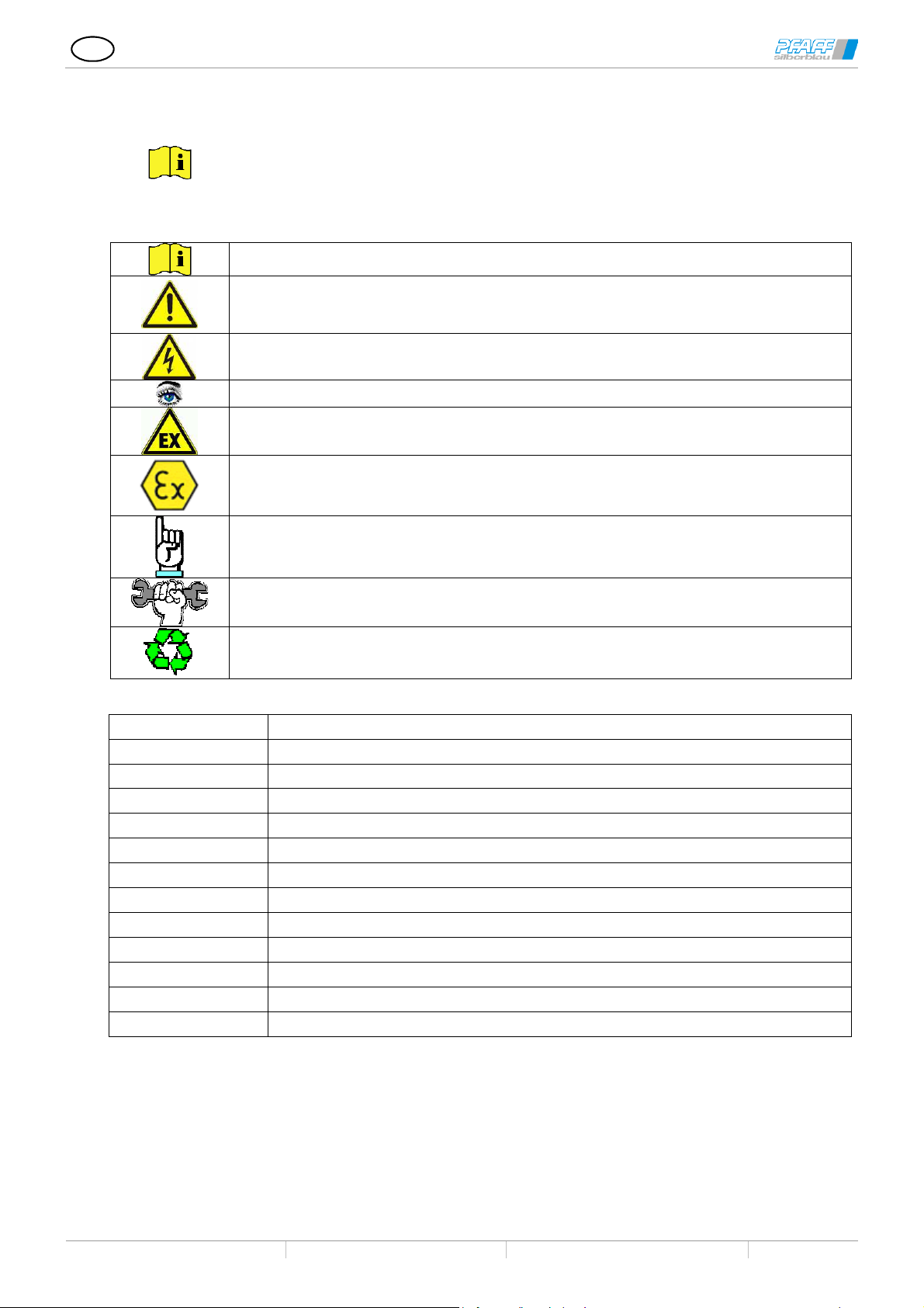
Practical information
Warning against a general hazard. Risk of injury due to neglect.
Warning against electrical voltage. Severe risk of injury due to neglect.
Information on the safety screw jacks
Danger of explosion
Important information for use in spaces with explosion hazards
T13.01.000.0000.0003
2019/04 Rev. Index E
Important information
Assembly and setting information
Disposal
SHE Worm gear screw jack
HSE High-performance worm gear screw jack
Type 1 (Ba1) Method of operation for type with lifting screw
Type 2 (Ba2) Method of operation for type with rotating screw
Specifications A = screw on housing cover side; B= screw on mounting surface side
Tr Trapezoidal thread spindle
Ku Ball screw spindle
S Buttress thread screw
P Screw pitch
DIN German industry standards
EN European norm
ISO International standards
ID Duty cycle in % / h
Subject to technical modifications Design changes under reserve Sous réserve de modifications techniques !
3
Page 4
GB
Worm gear screw jacks are incomplete machines and are intended for installation in complete machines or
that are employed for converting rotational movement into longitudinal movement
the operating instructions, in the
Modifications to the screw jacks as well as the attachment of additional devices are only permitted with our
If stated in the order confirmation, the worm gear screw jacks with corresponding additional supplementary
e responsibility of the
The manufacturer of the complete system checks that the product in combination with the complete machine
or use in the existing Ex zone must be checked or assessed in
Worm gear screw jack SHE type1 and type2
High-performance screw jack HSE type1 and type2
T13.01.000.0000.0003
2019/04 Rev. Index E
1 Intended use
for assembly with several machines into a system.
They are drive elements
and for reducing speed or converting torque.
The drive systems may only be used for the designated purpose.
They may be used only under the application conditions specified in
technical documentation or in the order confirmation.
Operation outside the respective performance limitations / ambient conditions is not permitted.
Not suitable for use in explosive-atmosphere zones.
Not suitable for use in aggressive environments, if not constructed especially for these applications.
express and written authorisation.
Pay attention to the technical data and functional description!
equipment comply with the requirements of various standards and guidelines:
1.1 Screw jacks with safety devices for lifting platforms
in accordance with DIN EN 1570-1:2015-01; DIN EN 280:2014-02, DIN EN 1756, DIN EN 1493:2011-02
Screw jacks with safety devices such as limited pitch angle – safety nut, speed monitoring and/or wear monitoring
are designed or constructed according to the requirements of the applicable standard –
DIN EN 1570-1:2015-01 - Lifting tables
DIN EN 280:2014-02 - Elevating work platforms
DIN EN 1493:2011-02 – Vehicle lifts
DIN 56950-1:2012-05 – Event technology technical installations –
designed for installation in machines in accordance with the applicable standards.
The manufacturer of the complete system checks that the product in combination with the complete machine is in
conformity. The manufacturer of the complete system is responsible for conducting the risk assessment for the
complete system. The information in our operating instructions must be integrated in the instructions for the
complete machine.
Required prototype tests (experts' examinations) need to be carried out under th
manufacturer of the complete machine.
1.2 Worm gear screw jacks in accordance with ATEX guideline 2014/34/EC
are suited as components (2014/34/EC item 1 (3) for installation in machines for use in explosiveatmosphere zones as indicated by the ATEX marking.
For the ignition source analysis, the ATEX checklist must be filled out completely and submitted (www.pfaffsilberblau.com).
is ATEX conform, and is responsible for conducting the ignition source analysis for the complete system.
The information in our operating instructions must be integrated in the instructions for the complete machine.
The suitability of the ATEX components f
accordance with the ATEX marking, the order confirmation, conformity declaration and type plate.
Subject to technical modifications Design changes under reserve Sous réserve de modifications techniques !
4
Page 5
GB
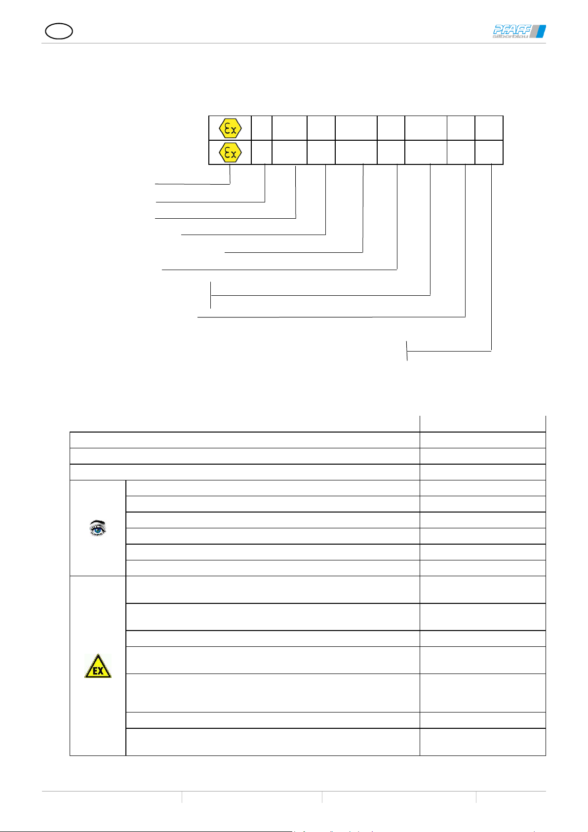
1.2.1 Marking in accordance with RL 2014/34/EC
Worm gear screw jack SHE type1 and type2
High-performance screw jack HSE type1 and type2
T13.01.000.0000.0003
2019/04 Rev. Index E
Gas
Dust
Ex-Symbol
Device group
Category
Ignition protection type
Equipment protection level (EPL)
Explosion group
Temperature class
Max. surface temperature
Equipment protection level
Equipment with partial certifikate,
CE Compliance is certified with Installation in a complete Equipment
2 Accident prevention guide
Observe the relevant instructions, regulations, and standards in the country of use. In Germany, these are
currently:
EC machinery directive 2006/42/EC
Machine safety DIN EN ISO 12100:2010
Lift devices DIN EN 1494:2009-05
Lifting tables DIN EN 1570-1:2015-01
Elevating work platforms DIN EN 280:2014-02
Loading platforms DINEN 1756
Vehicle lifts DIN EN 1493:2011-02
Stages and studios BGV C1
Stage mechanics, safety equipment DIN 56950-1:2012-05
EC guideline; Equipment and protective systems in potetially
explosive atmospheres (ATEX)
EC guideline; Improving the safety and health protection in
potentially explosive atmospheres
Explosion protection basics and methodology DIN EN 1127-1
Non-electric devices for use in explosive-atmosphere zones -
basics and requirements
Non-electric devices for use in explosive-atmosphere zones -
protection through constructional safety “c”, ignition source
monitoring "b"; liquid encapsulation “k”
Explosive atmosphere DIN EN 60079-0
Explosive atmosphere, projection, selection and set-up of
electrical systems
II 2G ck Ex h IIB T4 Gb U
II
2D c Ex h IIIB 135°C Db U
Rules and regulations
2014/34/EU
1999/92/EG (ATEX 137)
DIN EN ISO 80079-36
DIN EN ISO 80079-37
DIN EN 60079-14
Subject to technical modifications Design changes under reserve Sous réserve de modifications techniques !
5
Page 6
GB
Worm gear screw jack SHE type1 and type2
High-performance screw jack HSE type1 and type2
T13.01.000.0000.0003
2019/04 Rev. Index E
3 Safety information
3.1 General safety information
Operation, installation and maintenance may only be carried out by qualified personnel. The responsible
operator must be authorised in writing.
It is forbidden to transport people or to stay in the danger area of devices not designed for this purpose.
Exception: Screw jacks with safety features with corresponding intended use as described in Chapter 1.1
in the framework of the corresponding product standard.
Not suitable for use in explosive atmospheres!
Exception: Screw jacks are designed and marked as components for use in explosive-atmosphere
zones, as described in Chapter 1.2
Never reach into moving parts. Cover them or cut off access to them.
Do not remove or disable the safety devices.
The operational and safety limit switches must ensure that the lifting process is safely stopped at the end
positions.
To prevent contact with rotating/moving parts, attach protective covers (such as bellows, shaft caps) or
make those areas of the machine inaccessible.
Screw/Travelling nut must be fastened on-site or be turn-secured or equipped with the optional torsional
lock (max. screw torque according to technical documents). The construction must be able to bear the
screw torque securely.
Ball thread spindles and multi-geared trapezoidal thread spindles are not self-locking. An appropriate brake
device needs to be integrated into the system.
In the standard version, the screw does not have any protection against unintended skimming out of the
gear box (Ba1) or against the travelling nut driving out the screw. A protection against skimming needs to be
realised either on site or by worm gear screw jacks with mechanical end stops.
No lateral forces on the screw.
3.2 ATEX safety information
The owner of a system must ensure that the explosion-risk conditions are adhered to.
On-site layer thickness from surface coatings (e.g. lacquering) max. 2 mm (explosion group IIA and IIB) and
0.2 mm at explosion group IIC
Requirements for the reliable operation is a properly lubricated screw and a lift gear box provided with
lubrication.
The affects from knocks and bumps on the screw jack is not permitted.
Dust deposits are to be removed regularly.
Connect the screw jacks with potential equalisation (earth) and check the bleeder resistance (<106 Ohm).
Observe the speeds and permitted drive power output specified in the technical data when operating with
rotation speed control in the potentially explosive atmospheres.
On motorized drives, monitor the motor output with output gauges or otherwise temperature monitors (e.g.
thermistors (PTC) with evaluation device). Minimum requirements according to EN 13463-6 category 2IPL2; cat. 3 –IPL1.
Materials used must be resistant against the media.
The operator must count or measure the load cycles or operating hours and document them.
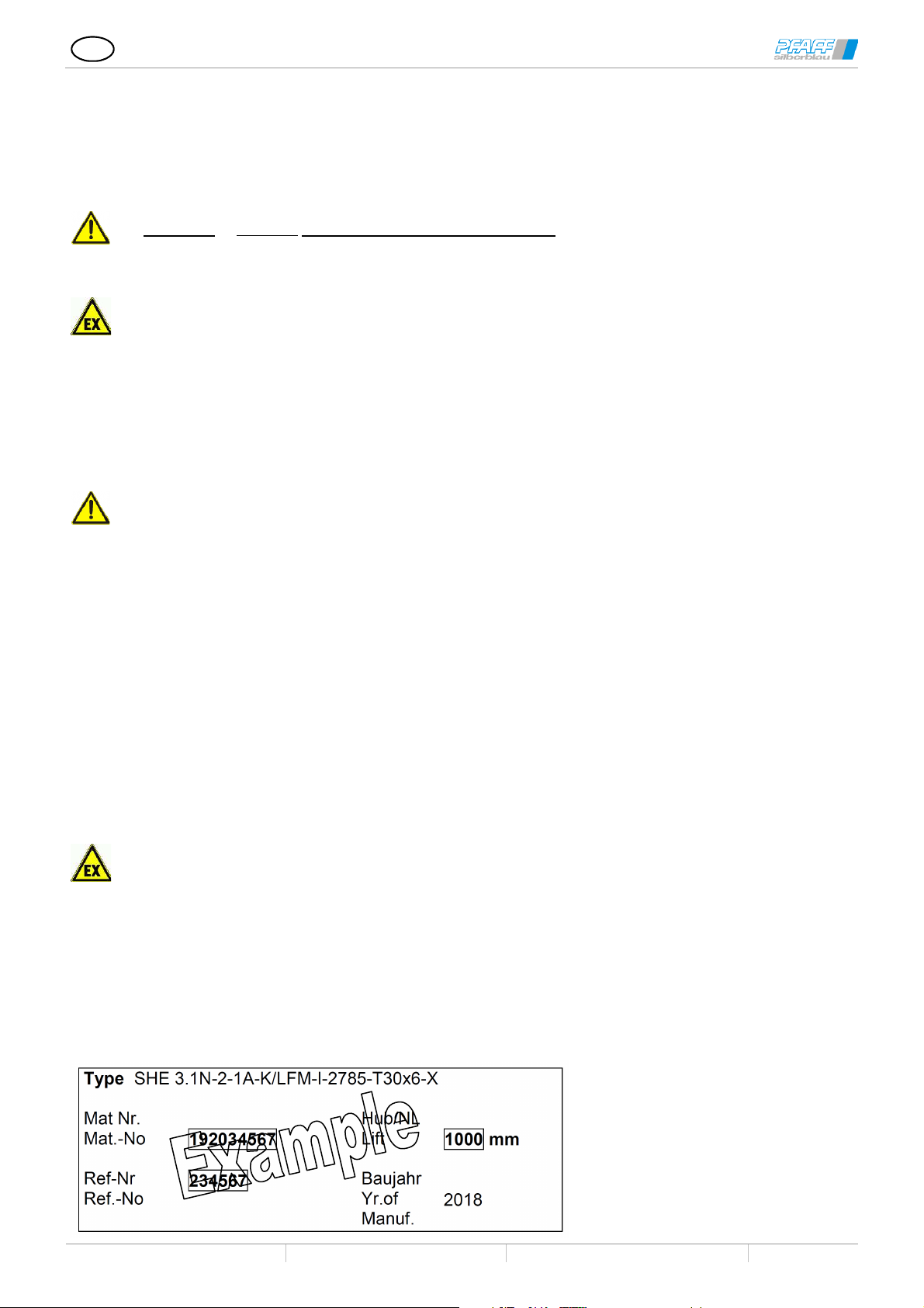
3.3 Type plate
Subject to technical modifications Design changes under reserve Sous réserve de modifications techniques !
6
Page 7

GB
Worm gear screw jack SHE type1 and type2
High-performance screw jack HSE type1 and type2
T13.01.000.0000.0003
2019/04 Rev. Index E
3.3.1 Design variants
In the stated variants, the first letter refers to the top side refers to the head side of the screw jack and the
second letter refers to the opposite side.
K Short lid
H High lid
F Guide ring
S/SR Sheath tube
SA Round sheath tube with stop collar
Sf Sheath tube with guide ring
Si Sheath tube with inductive limit switches
Sm Sheath tube with mech. limit switches
Se Sheath tube with mechanical
end stop (protection against skimming)
SV Reinforced rough sheath tube
V/VK Torsional lock through Square sheath
tube
Vi Torsional lock with ind. limit switches
Vm Torsional lock with mech. limit switches
Ve Torsional lock with end stop
VP Torsional lock by feather key
VV Reinforced sheath tube
SFM-O Short safety nut
SFM-K Short safety nut in tube cap
SFM-L Long safety nut
SFM-E Long safety nut, el. monitored
SFM-D Long safety nut, el. monitored
with speed monitoring
Pivot lug version
P = swivelling version
P = swivelling version with end stop
Pm = swivelling version with mechanical operational
limit switches
Pi = swivelling version with inductive operational limit
switches
Q = swivelling version (bore head IV, rotated 90° to
worm shaft)
Qe = swivelling version (bore head IV, rotated 90° to
work shaft) with end stop
Qm = swivelling version (bore head IV, rotated 90° to
work shaft) with mech. end stops
Qi = swivelling version (bore head IV, rotated 90° to
work shaft) with mech. end stops
Travelling nut
LFM Standard travelling nut
LSF Travelling nut with spanner flat
LSA Travelling nut with spherical contact
surface
EFM Single-flange nut (Tr or Ku)
LWZ Travelling nut with swivel pin
Combined with safety nut
-K Short safety nut
-L Long safety nut
-E Long safety nut, el. monitored
4 Technical specifications
4.1 High-performance worm gear screw jacks HSE, standard and with safety features
Sizes in the HSE series 32 36.1 50.1 63.1 80.1 100.1 125.1 140 200.1
Max. lifting force [kN] 5 10 25 50 100 200 350 500 1000
Max. tension [kN] 5 10 25 50 100 178 350 500 1000
Spindle Tr1
Ratio N 4:1 5:1 6:1 7:1 8:1 8:1 10 2/3:1 10 2/3:1 13 1/3:1
Lift per rotation at ratio N [mm/U] 1,0 1,0 1,33 1,28 1,5 1,5 1,5 1,5 1,5
Ratio L 16:1 20:1 24:1 28:1 32:1 32:1 32:1 32:1 40:1
Lift per rotation at ratio L [mm/U] 0,25 0,25 0,33 0,32 0,375 0,375 0,5 0,5 0,5
Max. drive capacity2 at 20°C ambient
temp. and 20% DC/h
Max. drive capacity2 at 20°C ambient
temperature and 10% DC/h
Overall efficiency ratio N [%] See efficiency table compendium worm gear screw jack
Overall efficiency ratio L [%] See efficiency table compendium worm gear screw jack
Spindle efficiency [%] 42,5 43 40 36,5 39,5 35,5 34 30 28,5
Torque-capacity-rotation speed at 20%
ID/hr. and 20°C
Screw torque at max. lifting force [Nm] 7,4 18,4 80 190 478 1060 2600 4235 11115
Max. permit. torque on the drive shaft [Nm] 12,6 29,4 48,7 168 398 705 975 1640 4260
Max. permit. screw length at pressure
load
18x6 24x5 40x8 50x9 60x12 70x12 100x16 120x16 160x20
[kW] 0,60 0,90 1,5 2,3 3,6 4,8 7,7 10,2 17,9
[kW] 1,0 1,5 2,6 4,0 6,3 8,4 13,5 17,9 31
See power table compendium on worm gear screw jacks
[mm] See offset diagram compendium worm gear screw jacks
1 Also with Ku screw
2 Max. permissible values with BA 1 and Tr screw. Higher values are possible using BA 2 or Ku screws
Subject to technical modifications Design changes under reserve Sous réserve de modifications techniques !
7
Page 8

GB
rotation speed at 20%
Lift per rotation at
Lift per rotation at
Max. drive capacity2 at 20°C ambient
Max. drive capacity2 at 20°C ambient
Overall efficiency
Overall efficiency
rotation speed at 20%
Max. permit. screw length at pressure
Worm gear screw jack SHE type1 and type2
High-performance screw jack HSE type1 and type2
T13.01.000.0000.0003
2019/04 Rev. Index E
4.2 Worm gear screw jack SHE standards and with safety features
Model series SHE unit size
Max. lifting capacity dyn/stat [kN] 5 10 30/45 50/75 100/150 200
Max. tensile load dyn/stat [kN] 5 10 30/45 50/75 99 178/200
Screw Tr3 18x6 24x5 30x6 40x7 60x12 70x12
Ratio N 10:1 5:1 6:1 6:1 7 2/3:1 8:1
Lift per rotation at
ratio N
Ratio L 20:1 20:1 24:1 24:1 24:1 24:1
Lift per rotation at
ratio L
Max. drive capacity4 at 20°C ambient
temp. and 20% DC/h
Max. drive capacity2 at 20°C ambient
temperature and 10% DC/h
Overall efficiency
ratio N
Overall efficiency
ratio L
Spindle efficiency [%] 54 43 40 36,5 39,5 37,5
Torque-capacity-
ID/hr. and 20°C
Screw torque at max. lifting force [Nm] 8,8 18,4 60 153 702 1009
Max. permit. torque on the drive shaft [Nm] 12 29,4 46,5 92 195 280
Max. permit. screw length at pressure
load
Model series SHE unit size
Max. lifting force
Max. tension
Screw Tr1
Ratio N
ratio N
Ratio L
ratio L
temperature and 20% DC/h
temperature and 10% DC/h
ratio N
ratio L
Spindle efficiency
Torque-capacityID/hr. and 20°C
Screw torque at max. lifting force
Max. permit. torque on the drive shaft
load
BG 0,5 1.1 3.1 5.1 15.1 20.1
[mm/U] 0,60 1,0 1,0 1,167 1,565 1,50
[mm/U] 0,30 0,25 0,25 0,292 0,50 0,5
[kW] 0,17 0,35 0,65 1,15 2,7 3,8
[kW] 0,25 0,55 0,9 1,65 3,85 5,4
[%] 31 29 27 24 27 24
[%] 24 20 19 16 17 17
See power table compendium on worm gear screw jacks
[mm] See offset diagram compendium worm gear screw jacks
BG 25 35 50.1 75 100.1 150 200.1
[kN] 250 350 500 750 800/1000 1500 2000
[kN] 250 350 500 750 800/1000 1500 -
90x16 100x16 120x16 140x20 160x20 190x24 220x28
10 2/3:1 10 2/3:1 10 2/3:1 12:1 12:1 19:1 17,5:1
[mm/U] 1,50 1,50 1,50 1,667 1,667 1,263 1,60
32:1 32:1 32:1 36:1 36:1 -
[mm/U] 0,5 0,5 0,5 0,556 0,556 -
[kW] 5,0 6,0 7,4 9,0 12,5 18,5
[kW] 7,2 8,6 10,4 12,6 17,5 26
[%] 22 21 15 18 15 15
[%] 15 14 10 12 9 -
[%] 36,5 34 30 31,6 28,5 28,8 29
See power table compendium on worm gear screw jacks
[Nm] 1725 2600 4235 7550 11115 19850
[Nm] 480 705 840 2660 2660 4260
[mm] See offset diagram compendium worm gear screw jacks
3Also with Ku screw
4 Max. permissible values with BA 1 and Tr screw. Higher values are possible using BA 2 or Ku screws
Subject to technical modifications Design changes under reserve Sous réserve de modifications techniques !
8
Page 9

GB
Worm gear screw jack SHE type1 and type2
High-performance screw jack HSE type1 and type2
T13.01.000.0000.0003
2019/04 Rev. Index E
4.3 Technical specifications ATEX
Worm gear screw jack for use in spaces with explosion hazards are designed based on the
environmental influences (ATEX checklist) that have been given to us. The technical specifications and
ATEX terms and conditions specified in the order confirmation must be adhered to. The manufacturer of the
total system needs to evaluate the suitability according to the identification.
The declaration of conformity, in accordance with guideline 2014/34/EC, is rendered void if the
technical data and ATEX conditions are not adhered to
4.3.1 Worm gear screw jacks SHE for explosive-atmosphere zones in acc. with 2014/34/EC (ATEX)
Model series SHE unit size
Max. lifting capacity dyn/stat [kN] 10 30/45 50/75 100/150 200 250
Max. tensile load dyn/stat [kN] 10 30/45 50/75 99 178/200 250
Screw Tr5 24x5 30x6 40x7 60x12 70x12 90x16
Ratio N 5:1 6:1 6:1 7 2/3:1 8:1 10 2/3:1
Lift per rotation at ratio N [mm/U] 1,0 1,0 1,167 1,565 1,50 1,50
Ratio L 20:1 24:1 24:1 24:1 24:1 32:1
Lift per rotation at ratio L [mm/U] 0,25 0,25 0,292 0,50 0,5 0,5
Max. drive capacity at 20°C ambient temperature and 20%
DC/h
Max. drive capacity at 20°C ambient temperature and 10%
DC/h
Overall efficiency ratio N [%] 29 27 24 27 24 22
Overall efficiency ratio L [%] 20 19 16 17 17 15
Spindle efficiency [%] 43 40 36,5 39,5 37,5 36,5
Torque-capacity-speed at 20% DC/h and 20°C See power table compendium on worm gear screw jacks
Screw torque at max. lifting force [Nm] 18,4 60 153 702 1009 1725
Max. permit. torque on the drive shaft [Nm] 29,4 46,5 92 195 280 480
Max. permit. screw length at pressure load [mm] See offset diagram compendium worm gear screw jacks
Model series SHE unit size
Max. lifting force [kN] 350 500 750 800/1000 1500 2000
Max. tension [kN] 350 500 750 800/1000 1500 Screw Tr 100x16 120x16 140x20 160x20 190x24 220x28
Ratio N 10 2/3:1 10 2/3:1 12:1 12:1 19:1 17,5:1
Lift per rotation at ratio N [mm/U] 1,50 1,50 1,667 1,667 1,263 1,60
Ratio L 32:1 32:1 36:1 36:1 -
Lift per rotation at ratio L [mm/U] 0,5 0,5 0,556 0,556 -
Max. drive capacity at 20°C ambient temperature and 20%
DC/h
Max. drive capacity at 20°C ambient temperature and 10%
DC/h
Overall efficiency ratio N [%] 21 15 18 15 15
Overall efficiency ratio L [%] 14 10 12 9 -
Spindle efficiency [%] 34 30 31,6 28,5 28,8 29
Torque-capacity-speed at 20% DC/h and 20°C See power table compendium on worm gear screw jacks
Screw torque at max. lifting force [Nm] 2600 4235 7550 11115 19850
Max. permit. torque on the drive shaft [Nm] 705 840 2660 2660 4260
Max. permit. screw length at pressure load [mm] See offset diagram compendium worm gear screw jacks
BG 1.1 3.1 5.1 15.1 20.1 25
[kW] 0,18 0,33 0,7 1,4 2,0 2,5
[kW] 0,35 0,65 1,15 2,7 3,8 5,0
BG 35 50.1 75 100.1 150.1 200.1
[kW] 3,0 3,8 4,5 6,5 9,5
[kW] 6,0 7,4 9,0 12,5 18,5
5Also with Ku screw
Subject to technical modifications Design changes under reserve Sous réserve de modifications techniques !
9
Page 10

GB
y and quality. Regrease for
Worm gear screw jack SHE type1 and type2
High-performance screw jack HSE type1 and type2
T13.01.000.0000.0003
2019/04 Rev. Index E
4.3.2 HSE for explosive-atmosphere zones in acc. with 2014/34/EC (ATEX)
Model series HSE unit size
Max. lifting force [kN] 10 25 50 100 200 350 500 1000
Max. tension [kN] 10 25 50 100 178 350 500 1000
Screw Tr6 24x5 40x8 50x9 60x12 70x12 100x16 120x16 160x20
Ratio N 5:1 6:1 7:1 8:1 8:1 10 2/3:1 10 2/3:1 13 1/3:1
Lift per rotation at ratio N [mm/U] 1,0 1,33 1,28 1,5 1,5 1,5 1,5 1,5
Ratio L 20:1 24:1 28:1 32:1 32:1 32:1 32:1 40:1
Lift per rotation at ratio L [mm/U] 0,25 0,33 0,32 0,375 0,375 0,5 0,5 0,5
Max. drive capacity at 20°C ambient
temperature and 20% DC/h
Max. drive capacity at 20°C ambient
temperature and 10% DC/h
Overall efficiency ratio N [%] See efficiency table compendium worm gear screw jack
Overall efficiency ratio L [%] See efficiency table compendium worm gear screw jack
Spindle efficiency [%] 43 40 36,5 39,5 35,5 34 30 28,5
Torque-capacity-rotation speed at 20% ID/hr.
and 20°C
Screw torque at max. lifting force [Nm] 18,4 80 190 478 1060 2600 4235 11115
Max. permit. torque on the drive shaft [Nm] 29,4 48,7 168 398 705 975 1640 4260
Max. permit. screw length at pressure load [mm] See offset diagram compendium worm gear screw jacks
36.1 50.1 63.1 80.1 100.1 125.1 140 200.1
[kW] 0,45 0,75 1,2 1,8 2,4 3,8 5,5 9
[kW] 0,9 1,5 2,3 3,6 4,8 7,7 10,2 17,9
See power table compendium on worm gear screw jacks
5 Receipt of goods, storage, transport
5.1 Receipt of goods
Startup with defective screw jacks is forbidden.
Immediately check if the contents of delivery correspond with the shipping documents upon receipt. No
other warranties can be approved for subsequent defect claims.
Claims on defects and incompleteness are to be made immediately at Pfaff-silberblau.
Claims on perceivable damages due to transport are to be reported to the transport company immediately.
Small parts such as limit switches are usually delivered unattached and packed individually.
5.2 Transport
Lift / transport the screw jack by the appropriate hoisting points.
Pay attention to the attachment parts. No person is to stand under suspended loads.
Use hoisting gear in good condition.
Keep long screws from getting warped. Support screw by appropriate means.
5.3 Storage
Storage period
< 3 years
Check corrosion protection; renew or repair, if necessary.
Check lubrication of moveable machinery, relubricate if necessary.
Check oil level of gears; refill, if necessary.
Check corrosion protection; renew or repair, if necessary.
Storage period
> 3 years
Check lubrication of moveable machinery, relubricate if necessary.
Clean spindle and grease with fresh lubricant along the whole length.
Drain gear oil, and fill gear unit with the prescribed oil quantit
grease lubrication.
6 Also with Ku screw
Subject to technical modifications Design changes under reserve Sous réserve de modifications techniques !
10
Page 11

GB
2
3
4
5
2
3
4
5
6
2
3
4
6
2
3
4
Worm gear screw jack SHE type1 and type2
High-performance screw jack HSE type1 and type2
T13.01.000.0000.0003
2019/04 Rev. Index E
General information
6 Worm gear screw jacks, standard version
Feature Description
Rotating worm wheel Ba1
Lifting screw Ba1
Rotating screw Ba2
Lifting travelling nut Ba2
SHE: Worm gear with grease lubrication
HSE: Worm gear with oil lubrication
Thread spindle with grease lubrication
Suitable for an ambient temperature
-10 to +40 °C
Translation thread or ball screw nut integrated into the worm wheel
Trapezoidal thread, buttress thread, multiple trapezoidal thread, ball
screw
From worm gear propelled trapezoidal, buttress, or ball thread spindle.
Travelling nut conducts the lift movement.
If the temperatures deviate from these specifications, the design must
be adapted by our technical office.
1 Screw
2 Worm wheel
3 Worm
4 Housing
5 Sheath tube
6 Travelling nut
6.1 Safety worm gear screw jacks
The worm gear screw jacks are equipped with a long safety nut, and an electric nut breakage monitoring
system for lifting tables acc. to EN 1570-1, elevating work platforms acc. to DIN EN 280, vehicle lifts acc. to
DIN EN 1493 and stages and studios acc. to BGV C1/DIN56950-1.
The manufacturer is responsible for the risk assessment of the entire system.
Feature Description
Safety nuts
Visual wear indicator
Electrical nut breakage monitoring
Self-locking/self-braking spindle
option
To protect against falling of the load in case of wear of the carrying nut.
For monitoring the wear of the carrying nut
For monitoring the carrying nut for breakage
On lift devices that must safely brake in the event of the failure of a
connection element, worm gear screw jacks with self-locking or selfbraking screws are required
Speed monitoring option
Standstill monitor option
Load monitor option
To monitor the synchronisation of all screw jacks or the standstill of a
screw jack in one lifting system with several worm gear screw jacks.
Electronic load monitor for monitoring the power of the drives
The selection of self-locking or braking options must be made on a case by case basis, taking into
account the complete system. Depending on lift speed and positioning accuracy, additional brake(s) will
be required.
Safety nut (wear monitoring)
Subject to technical modifications Design changes under reserve Sous réserve de modifications techniques !
11
Page 12

GB
Worm gear screw jack SHE type1 and type2
High-performance screw jack HSE type1 and type2
T13.01.000.0000.0003
2019/04 Rev. Index E
6.2 Safety nut (wear monitoring)
1 Visual wear monitoring
2 Inductive sensor
3 Pulse recession
4 Guide ring
5 Tube cab
6 Nut breakage limit switch
7 Travelling nut
8 Safety nut
Principle: With further wear, the gap X diminishes (documentation see 9.2.6)
Once the wear limit has been reached, the safety limit switch is activated.
The switch signals should be processed by the controller according to the requirements of the respective product
standards.
Only possible with trapezoidal thread spindles or buttress thread screws.
6.3 Safety-trap nut (option for ball screw spindles)
If the ball screw nut malfunctions, the ball screw spindle catches on the thread of the trap nut.
As a result, the power requirement of the drive motors increases. The unit needs to be
switched off by the controller or otherwise by a load monitor.
6.4 Options for screw jacks Ba1 and Ba2
6.4.1 Protection against skimming "Se", "Ve";
The end stop is a safety device and should not be used as a "working stop". If the end stop is run against
the block, this can cause damages to the screw or gears.
6.4.2 Ball thread spindle “Ku”
Please note during assembly and transport. Ball thread spindles are not self-locking.
Driving only permitted with a brake motor.
6.4.3 Multi-geared trapezoidal thread screws
Please note during assembly and transport. Multi-geared trapezoidal screw are not self-locking.
Driving only permitted with a brake motor.
6.4.4 Buttress thread screws "S"
Only in combination with 2 guide rings.
7 Assembly
Inspecting the used screw jacks for compliance with the technical requirements.
Add-on construction, supporting structure and groundwork is designed for the maximum forces.
For screw torques, see 7.11
Protect screws from soiling during transport, assembly, construction and storage.
Screws need to be protected during operation against soiling, e.g. by bellows, coils or on-site covers.
On worm gear screw jacks with oil lubrication, check the oil level, refill if necessary, insert bleed plug, pull
pin at bleed plug.
If necessary, mount and set limit switch.
Avoid misalignment and angular offset.
Provide movable load support points if necessary.
Distortions increase power consumption and reduce the service life!
Carry out assembly and run-in phase without explosive atmosphere.
The ATEX marking on the incorporated components must correspond to the existing
ATEX atmosphere.
Subject to technical modifications Design changes under reserve Sous réserve de modifications techniques !
12
Page 13

GB
Worm gear screw jack SHE type1 and type2
High-performance screw jack HSE type1 and type2
T13.01.000.0000.0003
2019/04 Rev. Index E
SHE Tr screw
HSE Tr screw
SHE Ku screw
HSE Ku screw
1. Align screw and screw jacks (e.g. with a spirit level, 0.3 mm/m), then screw tight, and anchor if necessary.
2. Make sure the screw is parallel to the on-site guides.
3. Avoid distortions. The worm shaft should turn easily and evenly throughout the entire lift height.
4. Clean screw and grease along the entire lift height.
5. For HSE and SHE with oil lubrication:
Pull tapered pin at the venting or insert pressure venting screw at the highest point.
Check lubrication level and top up if necessary.
6. For SHE with grease lubrication: Lubricate the gear using the grease gun at the lubrication nipple. Housing
needs to be filled completely with grease.
For HSE for the ATEX area, insert the pressure bleed plug at the highest
point for venting.
For multi-screw units
7. Check turning directions of all screw jacks.
8. Even out uneven support surfaces (use metal shims).
9. Move the screws/travelling nuts to the same height before depositing, aligning and fastening the
load.
To even out alignment errors between the individual elements, use rotationally elastic couplings,
rotationally elastic propeller shafts or cardan shafts.
Monitor the lubrication film and the screw temperature during the run-in phase. If there is rapid lubrication
consumption and excessive temperature despite compliance with the duty cycles and the maximum
capacity specifications, this indicates impermissible lateral forces.
7.1 Fitting positions SHE
Version A
Version B
Subject to technical modifications Design changes under reserve Sous réserve de modifications techniques !
13
Page 14

GB
Worm gear screw jack SHE type1 and type2
High-performance screw jack HSE type1 and type2
7.1.1 SHE oil fixtures with oil lubrication
Fitting
position
Pos 2
Pos 3
Pos 4
Pos 5
Pos 6
M1A
M1B
7.2 Fitting positions HSE
T13.01.000.0000.0003
2019/04 Rev. Index E
M2A
M2B
M3A
M3B
M4A
M4B
/
M5A
M5B
M6A
M6B
7.2.1 HSE oil fixtures
Oil sight glass or lock
screw
Version A
Mount
ing
position
Pos 1
Pos 2
Pos 3
Pos 4
Pos 5
Version B
M1A
M1B
M2A
M2B
Fill screw/
venting
M3A
M3B
/
/
M4A
M4B
Drain screw
M6A
M6B
1 Bleed plug
2 Venting pin
( pull at initial operation)
Pressure bleed plug
3 Oil level
(e.g. ATEX)
Tighten the venting screws always to the highest position.
Subject to technical modifications Design changes under reserve Sous réserve de modifications techniques !
14
Page 15

GB
4
Worm gear screw jack SHE type1 and type2
High-performance screw jack HSE type1 and type2
7.3 Pivot version
Version P Version Q
Version P or Q defines the position of the worm
shaft towards the swivel axis.
T13.01.000.0000.0003
2019/04 Rev. Index E
Display SHE (also deliverable as HSE)
No side forces due to alignment errors. Distortions increase power consumption and reduce the service life!
If necessary, install movable load support points or pivoting bearings.
Fasten screw jacks using only quality bolts and screws.
Secure bolts and screws.
7.4 Assembly of the inductive limit switches
1
3 2
Run switch cam on sight
Screw in the displacement sensor until it is aligned with the inner diameter of
the tube wall thickness.
Secure the sensor emitter by tightening the hexagon nut and ensure that the
emitter does not turn or the position is otherwise changed.
If the sensor protrudes toward the interior, it will be destroyed.
Observe the maximum tightening torque!
Material Type Maximum tightening torque [Nm]
M 8 2,5
1 Switching cam
2 Counter nut
Metal
M 12 7
3 Inductive sensor
4 Sensor fittings
M 18 35
Adjusting the switch point:
Loosen screws (4).
Slide the holding plate up or down
Tighten screws. Observe the tightening torques!
Subject to technical modifications Design changes under reserve Sous réserve de modifications techniques !
15
Page 16

GB
1 3 2
7.5 Assembly of electromechanical limit switches
1 Switching cam
2 Holding plate
3 Mechanical limit switch
4 Limit switch fittings
Worm gear screw jack SHE type1 and type2
High-performance screw jack HSE type1 and type2
1. Run switch cam on sight.
2. Screw the limit switch (3) onto the bracket; tighten screws only slightly.
Push the switch all the way in until the roll rests against the switch cam
phase.
3. Measure limit switch distance (for example, the back edge of the switch
housing).
4. Pull the limit switch back 1 mm and tighten it.
5. Carry out the lift test and set the actual lift.
Individual adjustments ± x according to the order confirmation / drawing
Secure screws against unintentional loosening.
Adjusting the switch point:
Loosen screws (4).
Slide the holding plate (3) up or down to the desired position.
Retighten the screws. Observe the tightening torques!
T13.01.000.0000.0003
2019/04 Rev. Index E
7.6 Assembly of safety nut
Pay attention to the installation position and force directions (pull/push)
The safety nut has to be placed subsequently in the load direction of the travelling nut.
Ba1
1 Wear indication ring
= Load direction
7.7 Installing the nut breakage limit switch (Ba1)
1. Screw the limit switch (6) onto the bracket; tighten screws only slightly. Push
the switch all the way in until the roll rests against the safety nut.
2. Measure limit switch distance (for example, the back edge of the switch
housing).
Ba2
3. Pull the limit switch back by the distance b (=1 mm) and tighten it.
Subject to technical modifications Design changes under reserve Sous réserve de modifications techniques !
Secure screws against unintentional loosening.
Observe the tightening torques!
16
Page 17

GB
7.8 Installing the nut breakage limit switch (Ba2)
7.8.1 Distance b, SHE series
Worm gear screw jack SHE type1 and type2
High-performance screw jack HSE type1 and type2
1. Screw limit switch (6) onto safety nut (8), slightly tighten screw (9).
2. Adjust distance of the limit switch (measurement b).
3. Tighten screws
Secure screws against unintentional loosening.
Observe the tightening torques!
T13.01.000.0000.0003
2019/04 Rev. Index E
Size Dimension b Distance X Limit switches Drawing no.
SHE 1.1 62,5 5 XCK T2110P16 13.02.103/0023
SHE 3.1 66 10 XCK T2110P16 13.02.105/0000-2600
SHE 5.1 68 10 XCK T2110P16 13.02.108/0000-2600
SHE 15.1 66 10 XCK T2110P16 13.02.109/0000-2600
SHE 20.1 66 10 XCK T2110P16 13.02.115/0028
86 10 XCK T2110P16 13.02.115/0027
SHE 25 87 10 XCK P102 13.02.012/0046-0000
SHE 35.1 94 15 XCK T2110P16 13.02.035/0016-0000
80 10 XCK T2110P16 13.02.035/
SHE 50.1 99 15 XCK T2110P16 13.02.113/0006
SHE 75 97 15 XCK T2110P16 13.02.075/0000-2300
SHE 100.1 15
7.8.2 Dimension b, HSE series
Size Dimension b Distance X Limit switches Drawing no.
HSE 32
HSE 36.1 66 10 XCK T2110P16 16.02.101/0000-0000Bl05
HSE 50.1 66 10 XCK T2110P16 16.02.113/0000-0000Bl05
HSE 63.1 66 10 XCK T2110P16 16.02.114/0000-0000Bl05
HSE 80.1 66 10 XCK T2110P16 16.02.104/0000-0000Bl05
HSE 100.1 130 15 XCK J 567 16.02.105/0000-0000Bl05
89,5 10 XCK P 2102P16 16.02.105/0013
HSE 125.1 88 15 XCK P 2102P16 16.02.106/0001-0000
7.9 Installing the pulse generator (rotational speed monitor)
7.9.1 Pulse by cam
1. Turn the worm wheel (worm) until the pulse cam is visible in the fixing
thread of the pulse generator.
2. Screw in the sensor until it contacts the outer diameter of the pulse
cam.
3. Turn the transmitter back again by 0.5 to 1 rotation until the distance
between the transmitter and the pin is between 0.5 and 1 mm
(measurement a).
4. Tighten the hexagon nut to fasten the pulse generator. When doing
this, ensure that the pulse generator does not turn!
Subject to technical modifications Design changes under reserve Sous réserve de modifications techniques !
17
Page 18

GB
Worm gear screw jack SHE type1 and type2
High-performance screw jack HSE type1 and type2
7.9.2 Pulse by recession or flattening
Should the sensor extend inwards, it will break and its sheared off parts have to be removed from
the gears.
Observe the maximum tightening torque!
7.10 Mechanical fastening
7.10.1 Screw jack housing
T13.01.000.0000.0003
2019/04 Rev. Index E
1. Turn the worm wheel (worm) until the pulse levelling is not visible in the
fixing thread of the pulse generator.
2. Screw in the pulse transmitter until it lies at the outer diameter of the
safety nut.
3. Turn the transmitter back again by 0.5 to 1 rotation until the distance
between the transmitter and the safety nut is between 0.5 and 1 mm
(dimension a).
4. Tighten the hexagon nut to fasten the pulse generator. When doing
this, ensure that the pulse generator does not turn!
SHE
Screws
(quality class min. 8.8)
Screws head II
Number of screws
HSE
Size
Screws
(quality class min. 8.8)
Number of screws
Size
0,5 1.1 3.1 5.1 15.1 20.1 25 35 50.1 75 100.1 150.1
M 8 M 8 M 12 M 16 M 18 M 24 M 33 M 33 M 42 M 42 M 48 M 48
M 6 M 8 M 12 M 16 M 18 M 24 M 24 M 30 M 30 M 42 M 48 M 48
2 4 4 4 4 4 4 4 4 6 6 8
32 36.1 50.1 63.1 80.1 100.1 125.1 140.1 200.1
M 8 M 8 M 12 M 16 M 20 M 24 M 36 M 42 M 64
4 4 4 4 4 4 8 4 4
7.10.2 Screw heads
SHE Size 0,5 1.1 3.1 5.1 15.1 20.1 25 35 50.1 75 100.1 150.1
a k6
∅
b
e
∅
n x ∅ f
Thread M
o H8
∅
l-
0.2
HSE
a k6
∅
b
e
∅
n x ∅ f
Thread M
o
∅
l
-0.2
Size
18h9 15 20 25 40 50 70 80 100 110 140 160
20 24 30 40 50 54 63 80 125 125 175 200
45 50 75 85 105 140 155 200 225 270 280 310
4 x 7 4 x 9 4 x 14 4 x 17 4 x 21 4 x 26 4 x 27 4 x 33 4 x 35 6x45 6 x 52 8x52
18x1.5 16x1.5 22x1.5 30x2 40x3 56x3 70x3 80x3 100x5 120x6 140x6 160x6
15 20 25 35 50 60 70 80 100 120 140 160
20 25 30 42 60 75 90 105 120 140 160 180
32 36.1 50.1 63.1 80.1 100.1 125.1 140.1 200.1
18h9 15 20 30 40 50 80 95 130
17 24 29 39 49 54 79 99 119
45 50 65 85 105 135 170 205 270
4 x 7 4 x 9 4 x 14 4 x 17 4 x 21 6 x 26 8 x 30 8 x 33 8 x 45
18x1.5 16x1.5 20x1.5 30x2 42x3 56x3 80x3 100x4 140x4
15 20 25 35 50 60 80 100 140
20 25 30 40 60 75 100 120 160
For the exact mounting dimensions, please request our dimensional drawings.
Subject to technical modifications Design changes under reserve Sous réserve de modifications techniques !
18
Page 19

GB
Worm gear screw jack SHE type1 and type2
High-performance screw jack HSE type1 and type2
7.10.3 Joint heads
Screw jacks with joint heads are available as special models.
When using joint bearings or joint heads, a torsional lock needs to be installed on
the gear side.
7.11 Screw tightening torques
Tightening torque M A [Nm]
Coarse-pitch thread
Quality 8.8 Quality 10.9 Quality 12.9
M 4
M 6
M 8
M 10
M 12
M 16
M 20
M 24
M 27
M 30
M 36
M 42
M 45
M 48
M 56
2,8 4,1
9,5 14
23 34
46 68
79 117
195 280
390 560
670 960
1000 1400
1350 1900
2330
3676
5502
5636
8856
T13.01.000.0000.0003
2019/04 Rev. Index E
4,8
16,5
40
79
135
330
650
1120
1650
2250
8 Initial operation
Always observe and follow these operating instructions when using the equipment.
Any use other than the intended use is prohibited.
Commissioning may only be performed by authorised personnel.
Check lubrication level.
Check limit switches.
Pay attention to the proper polarization of the electrical installation the the motor's sense of direction.
Put lift unit into operation without a load. (1x lifting 1x lower)
Operate intermittently, gradually increasing the load.
During initial operation, constantly control the operating temperature, the motor's current consumption and
the spindle contact pattern.
After 5 hours of operation, check that the screws are tight. Retighten where necessary.
Monitor the lubrication film and the screw temperature during the run-in phase. Rapid lubrication
consumption and excessive temperature indicate undue lateral forces even if the power-on time and the
maximum power specifications are complied with.
Carry out commission and run-in phase in secure explosive-free atmosphere.
Check the earthing of the mounted parts. (Discharge resistance less than 10
6
Ω)
Units for spaces with explosion hazards should be checked by a specially authorised person before
commissioning. (TRBS 1203-1). Observe the ATEX safety instructions in Chapter 3.2.
Check that the ATEX marking corresponds to the existing atmosphere.
Subject to technical modifications Design changes under reserve Sous réserve de modifications techniques !
19
Page 20

GB
lubrication level and refill
Worm gear screw jack SHE type1 and type2
High-performance screw jack HSE type1 and type2
T13.01.000.0000.0003
2019/04 Rev. Index E
9 Maintenance and inspection
Regular (at least 1x per year) inspection/maintenance must be performed by a qualified person (in acc. with
*)
TRBS 1203-1)
All tests and modifications must be documented (e.g. machine file, inspection log).
7
contracted by the operator.
The operator has to count or measure the alternations of load or operating hours and document them.
Risk analysis by the manufacturer of the overall system.
Carry out maintenance/inspection in secure explosive-free atmosphere.
Conduct a technical ATEX safety inspection by an especially qualified person (acc. to TRBS 1203-1) every 3
years.
Power must be turned off before maintenance and inspection of the unit.
Observe to the pertinent safety regulations during maintenance and inspection.
Support the load.
9.1 Maintenance plans
Screw jack
Every 50
hours of
operation**
Prior to
every
Quarterly
Every 300 hours of
operation or
annually
operation
SHE Ba1
Safety test
SHE Ba2
Grease the screw
Check the gear
lubrication level and
refill if necessary.
Damaged surface
treatment should be
HSE Ba1
properly repaired
immediately
Grease the
torsional lock
HSE Ba2
Check the screw's grease level and
refill if necessary.
Check screw jack externally for leaks.
Check the gear
if necessary.
** For special operating conditions, the lubrication intervals can be coordinated with us.
9.2 Maintenance instructions
9.2.1 Wear limits
Every 5 years
or after 1,000
hours of
operation
Change the
grease in the
gear box
Gear box oil
change
Tr screw
Max. wear [mm]
Tr screw
Max. wear [mm]
Tr screw
Max. wear [mm]
14x4 18x4 18x6 20x4 24x5 26x6.28 30x6 35x8 40x7
1,0 1,0 1,5 1,0 1,3 1,5 1,5 2 1,6
40x8 50x9 58x12 60x9 60x12 65x12 70x10 70x12 80x10
2 2,3 3,0 2,3 3,0 3,0 2,5 3,0 2,5
90x16 100x10 100x16 120x14 120x16 140x20 160x20 190x24 220x28
4,0 2,5 4,0 3,5 4,0 5,0 5,0 6,0 7,0
Wear limits of special pitches upon request or otherwise in operating instructions specific for the order.
7 We recommend having this check performed by the service department of CMCO.
Subject to technical modifications Design changes under reserve Sous réserve de modifications techniques !
20
Page 21

GB
Worm gear screw jack SHE type1 and type2
High-performance screw jack HSE type1 and type2
9.2.2 Standard screw jack with trapezoidal thread screw
Safety test:
The wear of the nut thread in the worm wheel / in the travelling nut needs
to be checked regularly, at least once per year.
Replacement is urgently required once the wear limit has been reached.
X = maximum wear (see Table 9.2.1)
9.2.3 Standard screw jack with ball thread screw
Safety test:
Pay attention to the running noises of the Ku screws during operation. An increase in noise indicates
wear of the Ku nuts. The nuts and screws need to be replaced promptly.
The Ku screws/nuts should generally be exchanged at the end of its service life.
9.2.4 Safety screw jacks
For utilisation in systems in acc. with EN 280, EN1570-1, EN1593; DIN 56950-1
In accordance with BetrSichV, lifting equipment must undergo an examination by an authorised person in
intervals (at least 1x per year) specified by the operator (TRBS 1203-1).8
9.2.5 Screw jacks with safety nut
T13.01.000.0000.0003
2019/04 Rev. Index E
Safety test:
Check the wear in the screw jacks (dimension x) of the
1 = Wear indication ring
translation thread in the worm wheel / travelling nut.
Prompt replacement of the carry nut and safety nuts is
required should the safety nut (wear indication ring) align
with the upper and lower edge of the housing or the wear
limit has been reached (dimension X).
Wear limit = X - max. wear
(see Table 9.2.1)
9.2.6 Wear measurement log
We recommend recording the new condition and the results from measuring the wear (dimension
X).
Screw jack 1 Screw jack 2 Screw jack. 3 Screw jack 4 Date/Signature
New condition
Dimension X
Wear measurement
on _____________
Wear measurement
on _____________
Wear measurement
on _____________
Wear measurement
on _____________
9.2.7 Spindle lubrication
Clean the screw with grease evenly with a brush.
We recommend an automatic lubricant dispenser in places of difficult accessibility, a longer power time or in
dirty environments.
Automatic lubricant dispensers are also available with ATEX conformity.
8 We recommend having this check performed by the service department of CMCO.
Subject to technical modifications Design changes under reserve Sous réserve de modifications techniques !
21
Page 22

GB
Worm gear screw jack SHE type1 and type2
High-performance screw jack HSE type1 and type2
T13.01.000.0000.0003
2019/04 Rev. Index E
9.2.8 Gear unit lubrication
For information on the oil level, location of the oil sight glasses, venting and drain screw, refer to Chapter
7.1.1 and 7.2.1 Mounting positions
9.2.9 SHE with grease lubrication
Lubricate the lubrication nipple (1) at the gear box with the grease gun.
Press the grease until it discharges from the seal lip or from the venting
bore.
Max. grease amount 20 ml or at least SHE 20.1 5% of the complete filling
amount (see 9.2.12)
Observe screw jack and attachment parts.
Remove excess grease (e.g. in sheath tube or bellows).
9.2.10 Grease the torsional lock (V)
Lubricate the lubrication nipple (2) at the guiding tube with the grease gun.
Grease amount about 20 ml at 500 mm lift height.
9.2.11 HSE and SHE with oil lubrication
Check oil fill level at the oil sight glass and refill if necessary.
Visual check for leaks
9.2.12 Lubrication amounts
SHE gear box with grease lubrication
SHE unit size 0,5 1.1 3.1 5.1 15.1 20.1
Grease amount about (kg)
0,05 0,1 0,2 0,35 0,9 2,0
SHE unit size 25 35 50.1 75 100.1 150.1 200.1
Grease amount about (kg)
1,3 2,5 4 5 10 10
Gear box with oil lubrication
SHE unit size 0,5 1.1 3.1 5.1 15.1 20.1
Oil amount about (l)
0,05 0,1 0,2 0,35 0,9 2,0
SHE unit size 25 35 50.1 75 100.1 150.1 200.1
Oil amount about (l)
1,3 2,5 4 5 10 10
HSE size 32 36.1 50.1 63.1 80.1 100 125 140 200
Oil amount about (l)
0,07 0,15 0,4 0,7 1,5 2,1 5,0 10 15,5
9.3 SHE with low-viscosity grease level in the lift gear box
Low-viscosity lubrication according to order confirmation, The maintenance of the lift gear box with lowviscosity grease level does not differ from screw jacks with standard grease filling.
Observe the types of grease according to the order confirmation
10 Decommissioning
When decommissioning the system, recycle or dispose of the various system components and/or screw
jacks according to the legal requirements.
Subject to technical modifications Design changes under reserve Sous réserve de modifications techniques !
22
Page 23

GB
Worm gear screw jack SHE type1 and type2
High-performance screw jack HSE type1 and type2
11 Lubricants
T13.01.000.0000.0003
2019/04 Rev. Index E
SHE/Merkur
gear box and
Tr. screws
SHE0.5-100
Ambient
temperature
range [°C]
-30 up to 0
-15 to +40
M1 –M8
+20 to +80
+40 to +180
SHE screws
BG150 / BG200
SHE gears
BG150 / BG200
SHE screws
(trapezoidal
thread)
HSE gear -30 up to 0
SHE gear
oil lubrication
Ku screws
0 to +50 °C
0 to +50 °C CLP VG 680
-30 up to 0
-15 to +80
+40 to +120
-15 to +40
+40 to +120 VG680
-30 up to 0 Synth. oil PGLP VG100 Klübersynth GH 6-100
-15 to +40
+20 to +80 Mineral oil CLP VG680
+40 to +120 Synth. oil PGLP VG680
-30 up to 0
-15 to +80
+40 to +120
Lubricant 1)
Grease KP2E-
40
Grease KP2K-
20
Grease KP2K-
20
Grease KP2S-
20
Grease KP0K-
20
Grease KP2E-
30
Grease KP2K-
20
Grease KP2S-
20
CLP-PG
Synth. oil
Mineral oil CLP VG220
Grease KP2E-
30
Grease KP1K-
20
Grease KP1K-
20
ISO-
NLGI1)
NLGI 2
NLGI 2
NLGI 2
NLGI 2
NLGI 0
VG 68 Klübersynth GH 6-80
VG220
NLGI 2
NLGI 1
NLGI 1
SKF LGLT 2 4)
EP 2 special
grease for lifting
gears
EP 2 special
grease for lifting
gears
SKF LGLT 2 4)
PS-Grease 011
Divinol ICL ISO
220 5)
SKF LGLT 2 4)
1)
1)
ISOFLEX LDS 18
Special A
Klüberplex
BE 11-462
Klüberplex
BE 11-462
Klübersynth
BH 72-422
Grafloscon C-SG
2000 Ultra
Klüberoil
GEM 1-680 N
ISOFLEX LDS 18
Special A
Klüberplex
GE 11-680
Klübersynth
BH 72-422
Klübersynth GH 6-220
Klübersynth GH 6-680
Klüber oil
GEM 1-220 N
Klüberoil
GEM 1-680 N
Klübersynth
GH 6-680
ISOFLEX LDS 18
SPEZIAL A
Stabutherm GH 461
Stabutherm GH 461
Molub-Alloy 243
Arktik
Molub-Alloy 936
SF Heavy
Optigear
BM 680
Molub-Alloy 243
Arktik
Molub-Alloy 936
SF Heavy
Tribol 800/220 Glycolube 220
Optigear
BM 220
Optigear
BM 680
gleitmo 585 K
URETHYN E/M 2
UNIREX
S 2
Beacon
EP 2
Beacon
EP 2
UNIREX
S 2
Spartan EP
220
Spartan EP
680
gleitmo 585K
gleitmo 585K
gleitmo 585K
URETHYN E/M 2
CEPLATTYN KG
10 HMF 2500
GEARMASTER
gleitmo 585K
gleitmo WSP
URETHYN E/M 2
Gearmaster
PGP 220
Gearmaster
PGP 680
Gearmaster
Gearmaster
Gearmaster
PGP 680
URETHYN E/M 2
CLP 680
5040
CLP 220
CLP 680
Printed bold = Standard lubricants: Factory-filed gear lubrication or otherwise lubrication recommendation for screws
Attention: The alternatives to our standard lubricants are specifications of the lubricant manufacturers.
Pfaff-silberblau does not have any references whether the lubricants meet the manufacturer specifications.
Lubricant selection: The temperature ranges refer to the ambient temperature. Higher lubricant temperatures that may result
during the operation of the drive elements have already been taken into account.
Standard temperature range: -15 °C to +40 °C
Only if the limits of the standard temperature range is exceeded should lubricants of other temperature ranges be
used.
To operate the drive elements in temperature ranges that deviate from the standard, design modifications are necessary
along with possible construction measures. Observe the technical data according to the order confirmation and the operating
instructions.
Observe the lubricant specifications in the type plate.
Mineral and synthetic lubricants should not be mixed together. It is recommended to generally not mix lubricants or to check
the composition.
1) Specifications refer to the factory lubricant
2) Critical start-up characteristics at low temperatures should be
observed.
4) SKF GmbH
5) Zeller+Gmelin GmbH & Co. KG
Used lubricants are to be disposed of in accordance with legal requirements!
Subject to technical modifications Design changes under reserve Sous réserve de modifications techniques !
23
Page 24

GB
Worm gear screw jack SHE type1 and type2
High-performance screw jack HSE type1 and type2
T13.01.000.0000.0003
2019/04 Rev. Index E
12 Einbauerklärung / Declaration of incorporation / Déclaration d'incorporation
für unvollständige Maschinen
im Sinne der EG-
Maschinenrichtlinie
2006/42/EG,
for incomplete machines
according to EC machine
directive 2006/42/EC,
Annex II, No. 1B
pour machines incomplètes
conformément à la directive
européenne relative aux
machines 2006/42/CE,
Anhang II, Nr. 1B
Spindelhubelemente SHE;
HSE Ba 1 und Ba 2
Worm Gear Screw Jack SHE
and HSE type 1 and type 2
Vérins à vis sans fin SHE et
HSE type 1 et type 2
annexe II, n 1B
Antriebselement zum Einbau in
eine Maschine
ist eine unvollständige Maschine nach Artikel
2g und ausschließlich zum Einbau in eine
Maschine oder zum Zusammenbau mit
anderen Maschinen oder Ausrüstung
vorgesehen.
Folgende grundlegenden Sicherheits- und
Gesundheitsschutzanforderungen gemäß
Anhang I dieser Richtlinie kommen zur
Anwendung und wurden eingehalten 1.1.2;
1.1.3; 1.1.5; 1.3.2; 1.3.3; 1.3.4; 1.3.7; 1.3.9;
1.5.2; 1.7.3; 1.7.4; 4.1.2.3; 4.1.2.6
Die speziellen technischen Unterlagen gemäß
Anhang VII B wurden erstellt und sie werden
der zuständigen nationalen Behörde auf
Verlangen in elektronischer Form übermittelt
Diese unvollständige Maschine ist in
Übereinstimmung mit den Bestimmungen der
folgenden EG Richtlinien
Angewendete harmonisierte Normen,
insbesondere:
Actuator element for assembly in
a machine
is an incomplete machine according to Article
2 g and has been designed exclusively for
installation in a machine or for assembly with
other machines or equipment.
The following basic health and safety
requirements in Annex I to this Directive are
applicable and have been observed 1.1.2;
1.1.3; 1.1.5; 1.3.2; 1.3.3; 1.3.4; 1.3.7; 1.3.9;
1.5.2; 1.7.3; 1.7.4; 4.1.2.3; 4.1.2.6
The special technical documentation referred
to in Annex VII B has been prepared and will
be forwarded to the competent national
authority, upon request in electronic form
This incomplete machine is in compliance
with the provisions of the following EC
directives
Applied harmonised standards, in particular: Normes harmonisées utilisées, en
DIN EN 1494:2000; DIN EN ISO 12100:2010
Angewendete nationale Normen und
technische Spezifikationen, insbesondere:
Applied national technical standards and
specifications, in particular:
Diese unvollständige Maschine darf erst
dann in Betrieb genommen werden, wenn
festgestellt wurde, dass die Maschine, in die
diese unvollständige Maschine eingebaut
werden soll, den Bestimmungen der EGMaschinenrichtlinie entspricht
This incomplete machine may only be put
into operation if it has been determined that
the machine into which this incomplete
machine will be installed complies with the
provisions of the EC machine directive
Ort/Datum Kissing, 03.04.2019
Propulsife élément pour
assemblée dans une machine
est une machine incomplète selon l'article 2g
et a été conçue uniquement pour être montée
dans une machine ou à être assemblée avec
d'autres machines ou équipement.
Les exigences suivantes de sécurité et
relatives à la santé, conformes à l'annexe I de
cette directive, ont été appliquées et
respectées 1.1.2; 1.1.3; 1.1.5; 1.3.2; 1.3.3;
1.3.4; 1.3.7; 1.3.9; 1.5.2; 1.7.3; 1.7.4; 4.1.2.3;
4.1.2.6
La documentation technique spéciale
conforme à l'annexe VII B a été préparée et
sera transmise aux autorités nationales
compétentes, également sous forme
électronique, si nécessaire.
Cette machine incomplète est conforme aux
dispositions des directives européennes
suivantes
particulier :
Normes et spécifications techniques
nationales qui ont été utilisées, notamment
Cette machine incomplète ne doit être mise
en service que lorsqu'il a été déterminé, que
la machine dans laquelle cette machine
incomplète doit être montée, est conforme
aux dispositions de la directive européenne
relative aux machines
Der Unterzeichnende ist bevollmächtigt die
technischen Unterlagen gemäß Anhang VII A
zusammenzustellen und der zuständigen Behörde
auf Verlangen zu übermitteln.
The undersigned is authorised to prepare the
technical documentation referred to in Annex VII A
and submit it to the responsible authorities on
request.
Le signataire est habilité à réunir la documentation
technique spéciale conforme à l'annexe VII A et à la
transmettre aux autorités compétentes si
nécessaire.
Columbus McKinnon Engineered Products GmbH
Am Silberpark 2-8
D-86438 Kissing, Germany
Phone: +49(0)8233 2121 800
Fax: +49(0)8233 2121 805
Page 25

GB
Worm gear screw jack SHE type1 and type2
High-performance screw jack HSE type1 and type2
T13.01.000.0000.0003
2019/04 Rev. Index E
Einbauerklärung Declaration of
incorporation
für unvollständige Maschinen
im Sinne der EG-
Maschinenrichtlinie
2006/42/EG,
Anhang II, Nr. 1B
Spindelhubelemente SHE;
HSE Ba 1 und Ba 2
for incomplete machines
according to EC machine
directive 2006/42/EC,
Annex II, No. 1B
Worm Gear Screw Jack SHE
and HSE type 1 and type 2
Déclaration
d'incorporation
pour machines incomplètes
conformément à la directive
européenne relative aux
machines 2006/42/CE,
annexe II, n 1B
Vérins à vis sans fin SHE et
HSE type 1 et type 2
mit Sicherheitseinrichtungen with safety devices avec équipement de sûreté
Antriebselement zum Einbau in
Hubtische, Hebebühnen,
Hubarbeitsbühnen oder
Fahrzeughebebühnen
ist eine unvollständige Maschine nach Artikel
2g und ausschließlich zum Einbau in eine
Maschine oder zum Zusammenbau mit
anderen Maschinen oder Ausrüstung
vorgesehen.
Folgende grundlegenden Sicherheits- und
Gesundheitsschutzanforderungen gemäß
Anhang I dieser Richtlinie kommen zur
Anwendung und wurden eingehalten 1.1.2;
1.1.3; 1.1.5; 1.3.2; 1.3.3; 1.3.4; 1.3.7; 1.3.9;
1.5.2; 1.7.3; 1.7.4; 4.1.2.3; 4.1.2.6
Die speziellen technischen Unterlagen gemäß
Anhang VII B wurden erstellt und sie werden
der zuständigen nationalen Behörde auf
Verlangen in elektronischer Form übermittelt
Diese unvollständige Maschine ist in
Übereinstimmung mit den Bestimmungen der
folgenden EG Richtlinien
Angewendete harmonisierte Normen,
insbesondere:
DIN EN ISO 12100:2010; DIN EN 1494:2000; EN1570; EN280; EN1756; EN1493
Angewendete nationale Normen und
technische Spezifikationen, insbesondere:
Diese unvollständige Maschine darf erst
dann in Betrieb genommen werden, wenn
festgestellt wurde, dass die Maschine, in die
diese unvollständige Maschine eingebaut
werden soll, den Bestimmungen der EGMaschinenrichtlinie entspricht
Ort/Datum Kissing, 03.04.2019
Actuator element for assembly in
lifting tables, lifting platforms,
working platforms or vehicle lifting
platforms
is an incomplete machine according to Article
2 g and has been designed exclusively for
installation in a machine or for assembly with
other machines or equipment.
The following basic health and safety
requirements in Annex I to this Directive are
applicable and have been observed 1.1.2;
1.1.3; 1.1.5; 1.3.2; 1.3.3; 1.3.4; 1.3.7; 1.3.9;
1.5.2; 1.7.3; 1.7.4; 4.1.2.3; 4.1.2.6
The special technical documentation referred
to in Annex VII B has been prepared and will
be forwarded to the competent national
authority, upon request in electronic form
This incomplete machine is in compliance
with the provisions of the following EC
directives
Applied harmonised standards, in particular: Normes harmonisées utilisées, en
Applied national technical standards and
specifications, in particular:
Propulsif élément pour installation
dans table de levage, plateforme
élévatrice, plateforme de travaille,
plateforme de levage pour véhicule
est une machine incomplète selon l'article 2g
et a été conçue uniquement pour être montée
dans une machine ou à être assemblée avec
d'autres machines ou équipement.
Les exigences suivantes de sécurité et
relatives à la santé, conformes à l'annexe I de
cette directive, ont été appliquées et
respectées 1.1.2; 1.1.3; 1.1.5; 1.3.2; 1.3.3;
1.3.4; 1.3.7; 1.3.9; 1.5.2; 1.7.3; 1.7.4; 4.1.2.3;
4.1.2.6
La documentation technique spéciale
conforme à l'annexe VII B a été préparée et
sera transmise aux autorités nationales
compétentes, également sous forme
électronique, si nécessaire.
Cette machine incomplète est conforme aux
dispositions des directives européennes
suivantes
particulier :
Normes et spécifications techniques
nationales qui ont été utilisées, notamment
This incomplete machine may only be put
into operation if it has been determined that
the machine into which this incomplete
machine will be installed complies with the
provisions of the EC machine directive
Cette machine incomplète ne doit être mise
en service que lorsqu'il a été déterminé, que
la machine dans laquelle cette machine
incomplète doit être montée, est conforme
aux dispositions de la directive européenne
relative aux machines
Der Unterzeichnende ist bevollmächtigt die
technischen Unterlagen gemäß Anhang VII A
zusammenzustellen und der zuständigen Behörde
auf Verlangen zu übermitteln.
Subject to technical modifications Design changes under reserve Sous réserve de modifications techniques !
The undersigned is authorised to prepare the
technical documentation referred to in Annex VII A
and submit it to the responsible authorities on
request.
Le signataire est habilité à réunir la documentation
technique spéciale conforme à l'annexe VII A et à la
transmettre aux autorités compétentes si
nécessaire.
25
Page 26

GB
Worm gear screw jack SHE type1 and type2
High-performance screw jack HSE type1 and type2
T13.01.000.0000.0003
2019/04 Rev. Index E
13 EG-Konformitätserklärung EC-Declaration of Conformity Déclaration "CE" de Conformité
im Sinne der
ATEX Richtlinie 2014/34/EU
ATEX Directive 2014/34/EU
Anhang X B
Hiermit erklären wir, dass Herewith we declare that the supplied model
Spindelhubelemente SHE; HSE
of
Worm Gear Screw Jack SHE and
Ba 1 und Ba 2
ein Gerät im Sinne der RL 2014/34/EG
Artikel 1 (3) ist und die Anforderungen
gemäß Anhang II der RL 2014/34/EG
erfüllt.
Das Spindelhubelement ist geeignet
an equipment as defined by EC
Directive 2014/34/EC article 1(3) is and
fulfills the requirement according to
annex II of the Directive 2014/34/EC
The worm gear screw jack is
für den Einsatz in
explosionsgefährdeten Bereichen
hazardous environment according
entsprechend der Kennzeichnung
as defined by
annex X B
HSE type 1 and type 2
suitable for the operation in
to the marking
conformément à la directive "CE"
ATEX 2014/34/EU
Annexe X B
Nous ne déclarons que le modèle
Vérins à vis sans fin SHE et HSE
type 1 et type 2
un appareil dans le sens de la directive
2014/34/EC article 1 (3) est et les
exigences conformément à l'annexe II
de la directive 2014/34/EC ré
vérins à vis sans fin est approprié
pour l'application dans les secteurs
explosifs conformément au
marquage
II 2G ck-Ex h IIB T4 Gb U
Angewendete harmonisierte Normen,
insbesondere:
II 2G D c-Ex h IIIB T135°C Db U
Applied harmonised standards, in particular: Normes harmonisées utilisées, notamment
DIN EN 1127-1-2011 (Explosionsschutz Grundlagen und Methodik/ Explosion prevention Basic concepts
and methodolgy/ Prévention de l’explosion Notations fondamentales et
méthodologie)
DIN EN ISO 80079-36 (Grundlagen und Anforderungen/ Basic method and requirement/
Prescriptions et méthode de bases)
DIN EN ISO 80079-37 (Schutz durch konstruktive Sicherheit „c“, Zündquellenüberwachung „b“,
Flüssigkeitskapselung „k“
Non-electrical type of protection constructional safety ’’c’’, control of ignition
sources ’’b’’,liquid immersion ’’k’’
Mode de protection non électrique par sécurité de construction "c", par contrôle de
la sourced’inflammation "b", par immersion dans un liquide "k"
2014/34/EU Anhang VIII / Annex VIII / annexe VIII
Angewendete nationale Normen und
technische Spezifikationen, insbesondere:
Applied national technical standards and
specifications, in particular:
Normes et spécifications techniques
nationales qui ont été utilisées, notamment
Auftragsbestätigung bzw. technisches Datenblatt sind Bestandteil dieser Konformitätserklärung.
Order confirmation or technical data sheet is part of these declaration of conformity
Vor Inbetriebnahme ist die gesamte Anlage durch eine, für
Explosionsgefährdung, besonders befähigte Person zu prüfen.
Die technische Dokumentation für Spindelhubelemente der
Kategorie 2 ist bei der benannten Stelle 0035 unter der
Registriernummer 296/Ex-Ab 1498/10 hinterlegt.
Ort/Datum Kissing, 03.04.2019
Before commissioning, the complete system must be
inspected by a person specifically qualified in explosion
hazards.
The technical documentation for worm gear screw jacks for
category 2 is deposited at the notified body 0035 under
registration number 296/Ex-Ab 1498/10.
Subject to technical modifications Design changes under reserve Sous réserve de modifications techniques !
26
 Loading...