

Page 1

Service
Manual
-900/16;/56;-966/05
for
Nr.
296-12-1'»
6i6
Pfaff
Series
240
and
1240
Page 2
Service manual for subclass
-*900/.Pfaff
series 240 and 1240
Note:
The adjustments in this service manual apply to Pfaff machine classes 241,
242, 244, 245 and 246 (small vertical hook) and to classes 1241, 1242, 1243,
1244, 1245 and 1246 (large vertical hook).
Deviations
in
the
various
in
such
data
sections.
as
Needle rise positions:
Models
Models B/C and C:
Models C/D:
Thread trim speed: 150
A
and
r.p.m
B:
1.6
2.0
2.2
mm
mm
to
Tools and other equipment for adjustment
Set
of screwdrivers,
Set of
alien
keys
from
blade
2 to 6
width 2 to 10
mm
needle
2.5
mm
mm
rise
and
clearances
are
indicated
as
such
Set of open-ended spanners
Metal
Sewing thread
rule
and
material
from
4 to 14
mm
Page 3
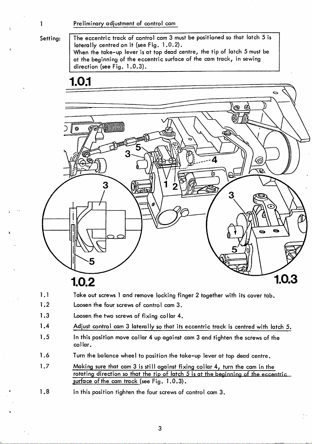
Preliminary adjustment of control cam
Setting;
The eccentric track of control cam 3
laterally centred on it (see Fig.
When
the take-up lever is at top dead centre, the tip of latch 5
must
1.0.2).
be positioned so that latch 5 is
at the beginning of the eccentric surface of the
direction (see Fig.
1
ni
1.0.3).
I)
cam
track, in
o
must
sewing
be
1.1
1.2
1.3
1.4
1.5
1.6
1.7
1.8
1.0.2
Take out screws 1 and remove locking finger 2 together with its cover tab.
Loosen
Loosen
Adjust control cam 3 laterally so that its eccentric track is centred with latch 5.
In this position
collar.
Turn
Making sure that cam 3 is still against fixing
rotating direction so that the tip of latch 5 is at the beginning of the eccentrir
surface of the cam track (see Fig.
In this position tighten the four screws of control com
the
four
screws
the two screws of fixing collar
move
of
control
com
3.
4.
collar 4 up against cam 3 and tighten the
screws
of the
the balance wheel to position the take-up lever at top dead centre.
collar4,turn the cam in the
1.0.3).
3.
Page 4
2
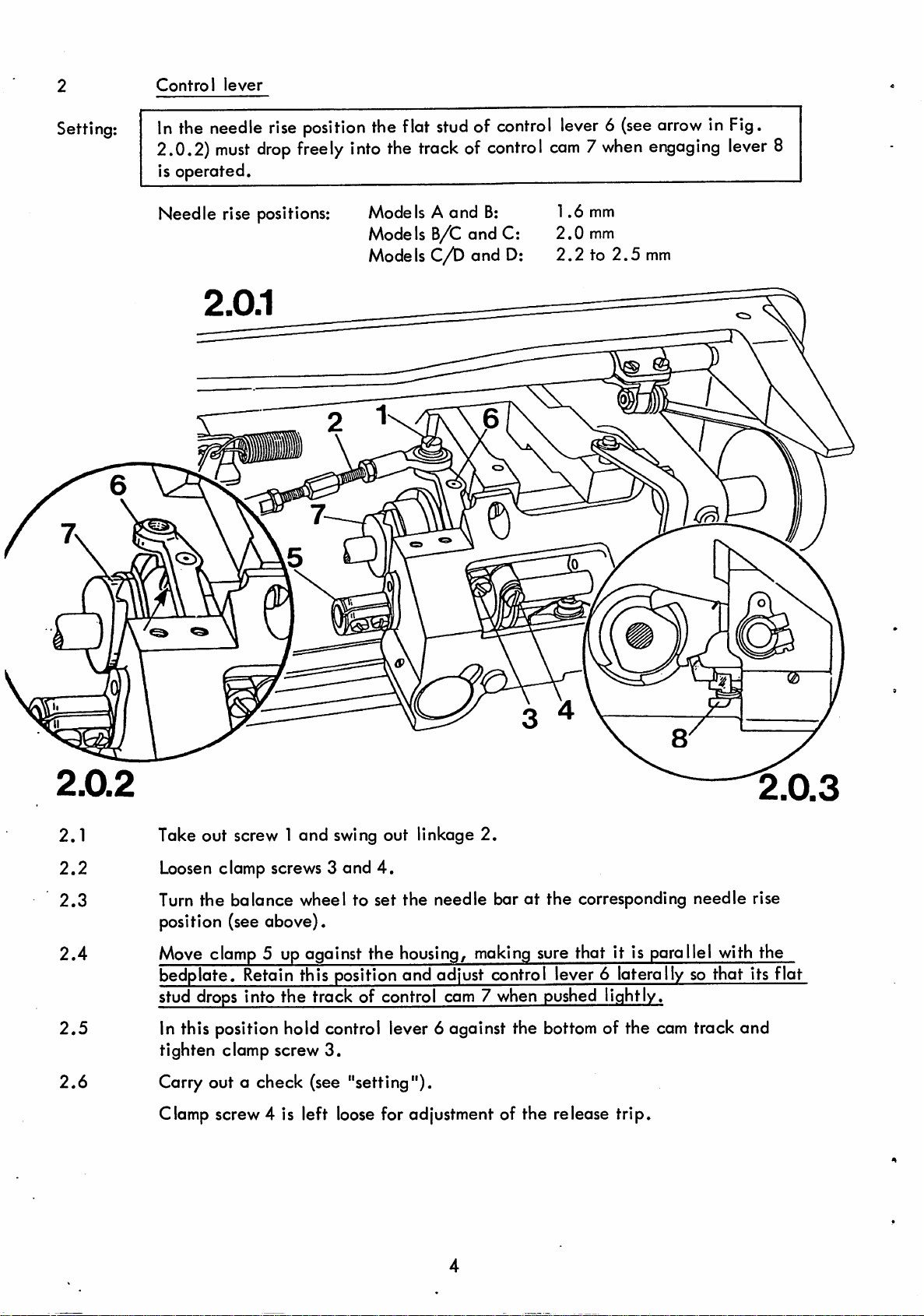
Control
lever
Setting:
In
the needle
2.0.2)
must
is operated.
Needle
rise positions:
rise
drop
position
freely
the flat
into
Models
the
studofcontrol
trackofcontrol
A
and
Models B/C and C:
Models C/D and D:
B:
lever6(see
com7when
1.6
mm
2.0
mm
2.2
to
2.5
arrow
engaging
mm
in Fig.
lever
8
2.0.2
2.1
2.2
2.3
2.4
2.5
2.6
2.0.3
Take out screw 1 and swing out linkage 2.
Loosen
Turn the balance wheel to set the needle baratthe corresponding needle rise
position (see above).
Move clomp 5 up against the housing, making sure that it is parallel with the
bedplate. Retain this position and adjust control lever 6 laterally so that its flat
stud drops into the track of control cam 7 when pushed lightly.
In this position hold control lever 6 against the bottom of the cam track and
tighten clamp screw
Carry out a check (see "setting").
Clamp screw 4 is left loose for adjustment of the release trip.
clomp screws 3 and
3.
4.
Page 5
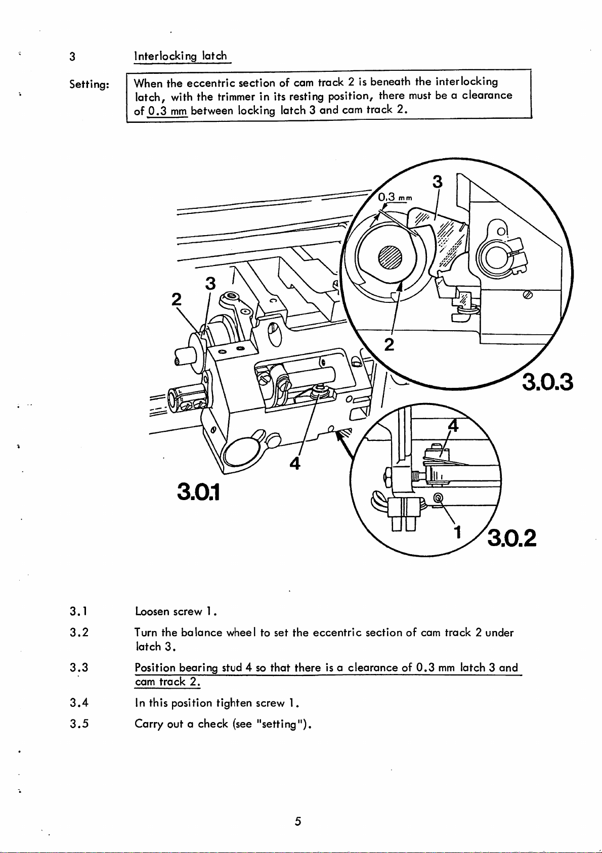
3
Interlocking latch
Setting:
When the
latch,
of 0.3
with
mm
eccentric
the
trimmer
between
section of cam track 2 is beneath
in its
locking
resting
latch
position,
3 and
cam
o
there
track
2.
the
interlocking
must
bea clearance
3.1
3.2
3.3
3.4
3.5
Loosen
Turn
latch
Position bearing stud 4 so
cam
In this position tighten screw 1.
Carry out a check (see "setting").
the
3.
track
screw
balance
2.
1.
wheel
to
set
that
the
eccentric
there is a
section
of
clearanceof0.3
com
track2under
mm
latch 3
and
Page 6
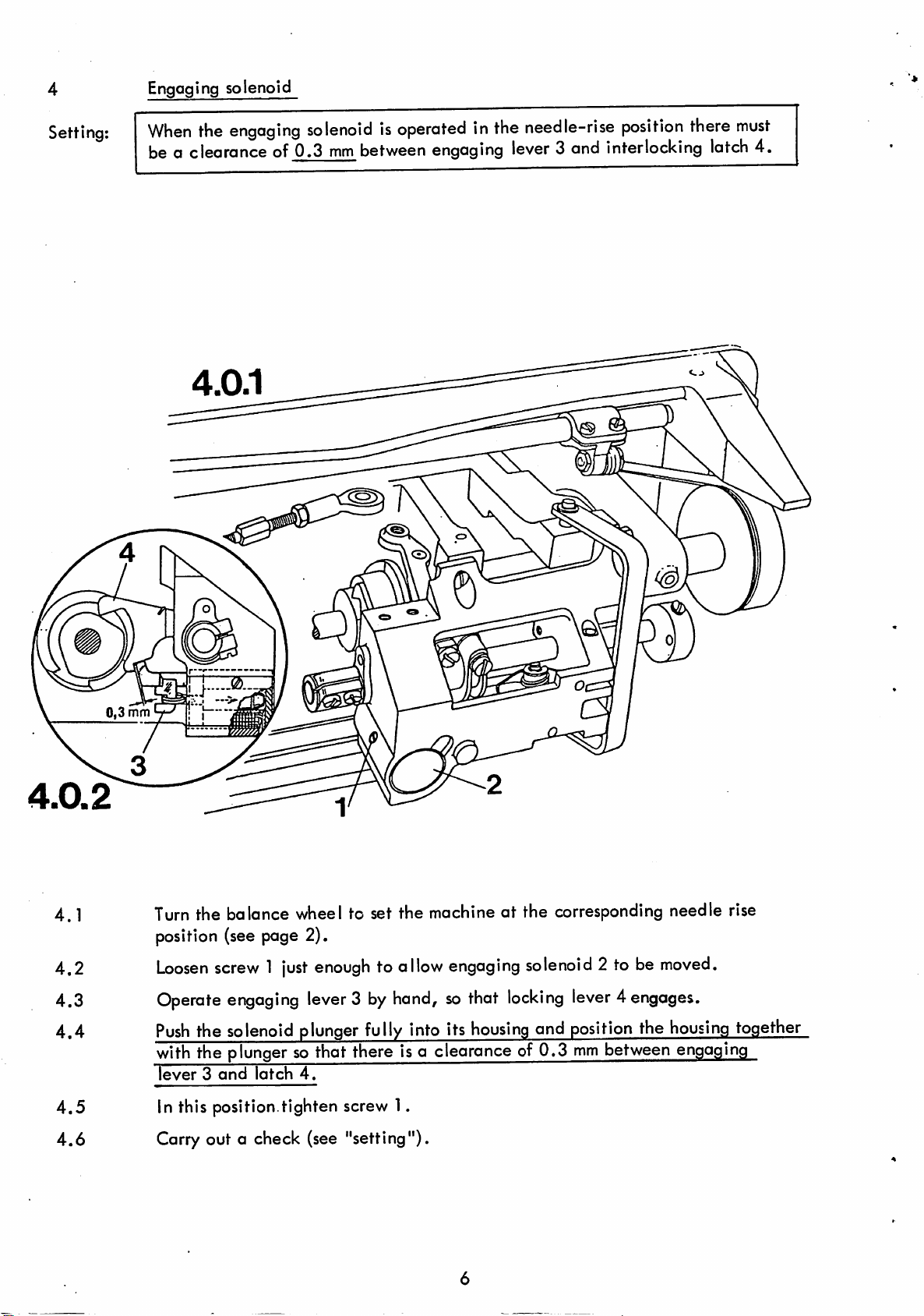
4
Engaging solenoid
Setting:
When
the
engaging
solenoidisoperatedinthe
be a clearance of 0.3
mm
between
engaging
needle-rise
lever
3 and interlocking
position
there
latch
must
4.
4.1
4.2
4.3
4.4
o
Turn
the balance wheel to set the machine at the corresponding needle rise
position (see page 2).
Loosen
Operate
Push
with
lever3and
screw1just
engaging
the
solenoid
the
plungersothat there isa clearanceof 0.3
latch
enoughtoallow
lever3by
plunger
4.
hand,sothat
fully
engaging
into its
housing
solenoid
locking
and
2 to be
moved.
lever4engages.
position
mm
the
between
housing
engaging
together
4.5
4.6
In this position.tighten screw 1.
Carry out a check (see "setting").
Page 7
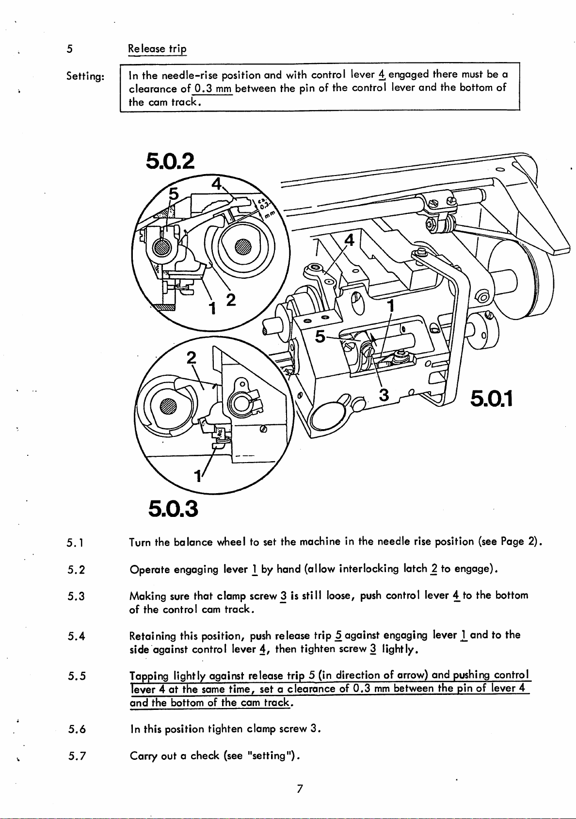
5 Release trip
Setting:
in the needle-rise
clearance of
the
cam
0.3
track.
position
mm
between the pin of the control lever and the
and
with
control
lever4engaged
there
o
must
bottom
bea
of
5.1
5.2
5.3
5.4
5.5
5.6
5.7
5.0.3
Turn
the balance wheel to set the machine in the needle rise position (see Page 2)
Operate
Making
of
the
Retaining
side against control lever 4, then tighten screw3 lightly.
Tapping
lever 4 at the same time, set a clearance of
and
In this position tighten clamp screw
Carry out a check (see "setting").
engaging
sure
that clamp screw3 is still
control
this position,
cam
lever
track.
by
hand
(allow
interlocking
loose,
push
release trip 5 against engaging lever
lightlyagainst release trip 5 (in direction of
the
bottom
of
the
cam
track.
3.
push
0.3
latch
2 to engage).
control lever 4 to the
J_and
arrow)
mm
between the pin of lever 4
and
pushing
bottom
to the
control
Page 8
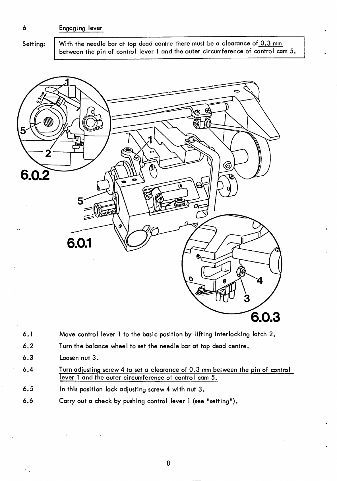
6
Engaging lever
Setting:
With
the needle bar at top dead centre there
must
be a clearance of 0.3
between the pin of control lever 1 and the outer circumference of control
mm
com
5.
6.1
6.2
6.3
6.4
6.5
6.6
Move control lever 1 to the basic position by lifting interlocking latch 2,
Turn the balance wheel to set the needle barattop dead centre.
Loosen
Turn adjusting screw 4 to set a
lever1and
In this position lock adjusting screw 4 with nut
nut
3.
the
outer
clearanceof0.3
circumference
of
control
mm
com
3.
between
5.
Carry out a check by pushing control lever 1 (see "setting").
6.0.3
the
pinofcontrol
Page 9
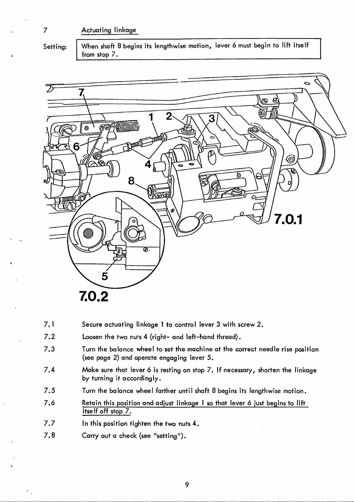
Actuating linkage
Setting:
When
from
shaft8begins
stop 7.
its
lengthwise
motion,
lever6must
begintolift
&
itself
7.1
7.2
7.3
7.4
7.5
7.6
7.7
7.8
7.0.2
Secure actuating linkage 1 to control lever 3 with screw
Loosen
Turn
the two nuts 4 (right- and left-hand thread).
the balance wheel to set the machineatthe correct needle rise position
(see page 2) and operate engaging lever 5.
Make sure that lever 6 is resting on stop 7. If necessary, shorten the linkage
by turning it accordingly.
Turn the balance wheel farther until shaft 8 begins its lengthwise motion.
Retain this position
itself
off
stop
In this position tighten the two nuts
7.
and
adjust
linkage 1 so
4.
that
lever 6 just begins to lift
Carry out a check (see "setting").
2.
Page 10

8
Final adjustment of the control cam
Setting:
When control lever 3 is engaged and the needle, moving up
centre, has reached a position 12
of
catcher
4 must
begin.
mm
above the needle plate, the movement
from
bottom dead
12mm
8.0.4
8.1
8.2
Turn the balance wheel to set the take-up lever a little past top dead centre.
Loosen
the
two
screws
in
control
cam1which
are
now
accessible.
Turn the balance wheel farther to set the machine at the needle rise position
(see page 2). Operate engaging lever 2.
8.3
8.4
8.5
8.6
8.7
8.8
Make sure the control lever is engaged, then
control
Turn
12
Retain this position
feelaresistance.
cam
1.
the balance wheel farther in sewing direction until the needle point is
mm
above the needle
plate.
and
turn control cam 1 in its rotating direction until you
loosen
the remaining
In this position tighten the accessible screws in control cam 1.
Turn
the balance wheel to gain access to the remaining
and
tighten these,
too.
screws
Carry out a check (see "setting").
10
screws
of control
of
cam
1
Page 11

9
Locking finger
Setting:
With the thread
mm
about 5
between
9.0.1
trimmer
locking
in its resting position there
finger 1 and control lever 3.
must
be a clearance of
9.1
9.2
9.3
9.4
—
9.0.2
Fit locking finger 1 with its tab and tighten screws 2 just a
Push
locking finger 1 fully in the direction of the arrow, then position it
laterallysothat
finger
and
control lever
In this position fully tighten screws 2.
Carry out a check (see "setting").
there
is a
clearanceofabout5mm
3.
between
little.
the
locking
11
Page 12

10 Secondary actuating linkage (only on two-needle machines)
Setting:
With
the thread
trimmer
centre to hole centre)
shafts
2.
in its resting position the
must
correspond with the distance between the centres of
length
of linkage 3
(from
hole
10.1
10.2
10.3
10.4
10.5
e
10.0.1
Make sure the trimming mechanism is in its resting position, then loosen the
two nuts 1 (right- and left-hand thread).
Measure
Adjust the length of linkage 3 so that the distance between levers 4 and 5
(measured
the
In this position lock the two nuts 1.
Carry out a check (see "setting").
centres
the
distance
between
of
shafts
between
the
2.
hole
the
centres)
centres
corresponds
of
shafts
2.
with
the
distance
between
12
Page 13

11
Catcher
height
Setting;
Adjustment
When
operating
sewing hook 4 by 0.1
3
to be
mode
the
take-up
positionbyhand,
2
leverisat
11
twice
mm.
on
two-needle
top
dead
the
lower
centre
catcher
ro^
machines
and
catcher2is
point
must
pushedtoits
clear
the
back
of
11.0.1
(S)
11.0.2
11.1
11.2
11.3
11.4
11.5
11.6 Carry out a check (see "setting").
Loosen
Loosen
Turn the balance wheel to set the take-up leverattop dead centre.
Set
hook
In this position, fully tighten the screws of fixing collar
that the latter is resting on the shaft bearing.
Clamp screw 1 is left
clamp screw 1 just enough to allow catcher 2 to turn.
the two screws in fixing collar
catcher
4.
2 so that its lower point is
loose
for the following adjustment.
3.
0.1
mm
above
the back of sewing
3,
making sure
13
Page 14

12
Trimmer
knife
Setting:
Adjustment
The
elongated
the knife
When
knife 3 must rest lightly on the catcher.
the
to be
made
twice
holeofthe
must
not touch the casting (see arrow).
point
of catcher 4
on two-needle
knife
mustbeparallel
has
passed
12.0.1
mm
machines.
with
about3mm
V
.
knife
beyond
bracket5,but
the
knife
edge,
7^
12.1 Make sure that clamp screw 1 is loose, then
12.2
First
position knife 3 so that it cannot collide
12.3 Position catcher 4 by hand so that its point protrudes
by
about
12.4
12.5
12.6 Carry out check (see "setting").
Push
touch the casting (see arrow) and its elongated hole is parallel with knife
bracket
In this position tighten the screws 2.
3 mm.
the knife lightly against the catcher and position it so that it does not
5.
14
loosen
with
the two screws 2.
catcher 4.
beyond
the knife edge
Page 15

13 Catcher reversal position
Setting:
Note:
13.0.1
Adjustment
in
the
reversal
cutting
When
in order to
edgeofknife4(see
clomp
to be
made
twice
on
positionofcatcher3its
arrowinFig.
screw
check
1 is
the
loosened,
"setting".
<S)
two-needle
the
following
%
back
13.0.2).
machines.
edge
mustbeflush
adjustments
have
with
to be
the
made
13.0.3
13.1
13.2
13.3 Retain this position and set catcher 3 so that its back edge is
13.4
13.5 Carry out a check (see "setting").
Make
rise
Continue
position.
cutting edge of knife 4
In
sure
position
this
position
that
clamp
andoperate the
turning
the balance
tighten
screw
(see
clamp
1 is
loose,
engaging
wheeltomove
arrow in Fig. 13.0.2).
screw1,making
15
then
lever.
set the
engaging
sure
machine
thereisno
shaft
at the
2 to its
flush
vertical
13.0.2
needle
for
left
with the
play,
Page 16

14 Bobbin
thread
trapper spring
Adjustment to be
Setting; Between the underside of catcher 4 and trapper spring 5 there
clearance of
position the end of the trapper
the
catcher
distanceof10
from
the inside of spring 5 to hollow stud 7 (see Fig.
be possible to
mode
0.3
mm
(see Fig.
(see arrow in
mm
on series 240 machines (12
remove
and replace the bobbin cose without hindrance.
twice on two-needle machines.
14.0.2).
spring
14.0.3).
When catcher 4 is in its reversal
mustbeflush
The trapper spring must be setata
with the back edge of
mm
on series 1240), measured
14.0.4).
14.0.2
(S
must
Also it
be a
must
rp
0
V.
14.0.4
2)
%
14.0.1
16
Page 17

14.1
Loosen
the
two
screws
1.
14.2
14.3
14.4
14.5
14.6
14.7 Re-connect spring 3 (Fig.
Position
of its elongated holes.
In
Disconnect spring 3 (Fig.
Swing
Retain
0.3
bracket 2 parallel
this
position
catcher 4
tighten the
across
this position and bend trapper
mm
between
the
catcher
with
two
14.0.5).
trapper
14.0.5).
the bedplateof the
screws
spring
1a little.
5 by hand.
spring5so
and
the
spring (see
machine
and at the
middle
that there is a clearance of
Fig.
14.0.2).
14.8 Set the machineat the needle rise position, operate the engaging lever, then
14.9
14.10
turn the balance wheel to set
Loosen
Position trapper spring
that the tips of the
screws
6.
5,
spring
catcher4at
and if necessary bracket 2, in the elongated hole so
are
flush
with
its reversal position.
the
bock
edge of catcher 4 (see
arrow
in Fig. 14.0.3) and the distance between the inside of the spring and hollow
stud 7 is about 10
14.11 In this position, tighten
mm
on Series 240 and 12
screws
1and 6 securely,
mm
on Series 1240 (see Fig.
making
sure that bracket 2
14.0.4)
is still parallel with the machine bedplate.
14.12 Carry out a check (see "setting").
17
14.0.5
Page 18

15
Tension
release
bracket
Setting;
With the
be a clearance of 7
With
the
trimmer
presser
in its resting position and th presser foot raised there
mm
between release bracket
foot
lowered
and the
edge of the rear positioning stop
discs
must
be released
just
enough
15.0.1
^and
(see
point
arrow
of catcher 6
in fig. 15.0.3) the
to allow the thread to
casting 4.
level
with
pass
through
must
the
tension
freely.
15.1
15.2
15.3
15.4
15.5
15.6
15.7
15.8
15.9
15.0.2
Check that the trimmer is in its resting position and the presser foot is raised,
then
loosen
Adjust
and
the
In this position, tighten the two screws 1.
Loosen
Turn
the balance wheel to set the machine in the needle rise position and
operate the engaging lever by hand.
Lower
Turn the balance wheel farther to set the point of catcher 6 level with
the back edge of the rear positioning stop.
Retain
the
two
screws
1.
the height of linkage rod 2 so that the clearance between release bracket 3
housing is
screw
about
5.
7 mm.
the presser foot onto the needle plate.
this position and
push
eccentric 7 (eccentric
15.0.3
lobe
facing
downwards)
towards the left together with release bracket 3 until the needle thread can
be easily pulled
In this position tighten screws
through
the
discs
of the thread tension.
5.
18
Page 19

16 Adjusting the synchronizer
16.1 On single-needle
Setting:
Adjustment
ha
Ives
On
sewing
also
(-720/02).
stops,
dead centre. After thread
leverattop dead
machines
with
Quick lever-operated
appliestotwo-needle
the
machine
centre.
must
trimming
halt
the machine
6!
machines
with
the
stop
motor^
with
disengageable
needle
must
bar4
mm
past
position with the take-up
type "700".
needle-bar
bottom
16.1.1
16.1.2
16.1.3
16.1.4
16.1.5
16.1.6
16.0.2
16.0.1
Remove
Loosen
Turn
Retain
switch-off
Turn
dead
Retain
switch-off
cap 1 and loosen cap screw 2 of synchronizer
the two retaining screws
4.
the balance wheel to set the needle bar 4
this
position
track
and
exactly
set
over
the
middle
the
carbon
of
the
brush,
insulated
mm
then
3.
past bottom dead centre.
segmentofthe
tighten
screws
the balance wheel (in sewing direction) to set the take-up lever at top
centre.
this
position
track
and
exactly
set
over
the
the
middle of
carbon
the
brush,
insulated
then
segmentofthe
tighten
cap
4.
screw
inner
outer
2.
16.1.7
16.1.8
Switch on the machine, check the positioning accuracy and re-adjust if
necessary.
Replace cap. 1.
19
Page 20

16.2
On
two-needle
machines with
Quick
lever-operated
Stop motor,
type
"700"
Setting: On
take-up
sewing
stops
leverattop dead
16.0.4
and after thread
centre.
trimming
the
machine
must
halt
with
the
16.2.1
16.2.2
16.2.3
16.2.4
16.2.5
16.2.6
16.2.7
16.2.8
16.0.3
Remove
Also loosen the two retaining screws
Turn
Retain this position and set the end of the insulated segment of the inner
gwitch-off track over the front end of the carbon brush holder (in sewing
direction) (see arrow in Fig.
(This
Turn the balance wheel to set the
Retain this position and set the middle of the insulated segment of the outer
switch-off track exactly over the carbon brush, then tighten cap screw
Switch on the machine and carry out a check (see "setting") and readjust
if necessary.
Replace cap 1.
cap 1 and
the balance wheel to set the needle barattop dead centre.
loosen
cop screw 2 of synchronizer 3.
4.
16.0.4),
then tighten retaining screws
adjustment does not set a stopping position.)
take-up
leverattop dead centre.
4.
2.
20
Page 21

16.3 On
single-
and
two-needle
machines
with
Quick
electronic
stop
motor,type
"800"
Setting:
On
sewing
stops
the
machine
dead centre. After thread
lever at top dead centre.
must
trimming
holt
the
with
the
machine
needle
must
bar4mm
position
past
with
bottom
the take-up
16.3.1
16.3.2
16.3.3
16.3.4
16.3.5
16.3.6
16.3.7
16.3.8
16.3.9
16.3.10
16.0.5
Remove
Loosen retaining screw 2.
Set the take-up lever at top dead centre.
Set
Set the needle bar 4
Set inner magnet tab 4 with the red magnet alsoatits opposite poleatthe bottom,
In this position tighten retaining screw 2.
Switch
Check the two positions by operating the pedal, and re-adjust if necessary.
Replace the cap on synchronizer 1.
the cap of synchronizer 1 on the balance wheel.
outer
magnet
on
the
tab
machine.
3 with the yellow magnetatits opposite poleatthe bottom.
mm
past bottom dead centre.
16.0.6
Note: A toggle switch makes it possible to switch off the function "4
of needle bar (two-needle machines); the machine will then only position with
the take-up lever
at
t.d.c.
21
mm
past
b.d.c.
Page 22

16.4
On
single-
and two-needle machines with Efka Variostop motor^type
"V".
Setting:
Note:
On sewing stops the machine
dead
centre.
After thread
dead
centre.
trimming
the machine
must
holt with the needle bar 4
must
position the take-up lever at top
mm
past bottom
If fitted, set the toggle switch on the motor, for selecting needle position
"4
mm
post
b.d.c."
at
"unten" (= down).
16.0.9
4
16.4.1
16.4.2
16.4.3
16.4.4
16.4.5
16.4.6
16.4.7
16.4.8
Note:
16.0.7
16.0.8
Loosen
Turn the balance wheel to set the take-up leverattop dead centre.
In this position turn the outer control disc 3 so that its slot isatthe bottom
between
Set the needle bar 4
In
the
Switch
Check the
Replace cover 1.
A toggle switch
of
the take-up leveratt.d.c.
the two retaining screws 2 and remove cover 1 of the synchronizer.
the
two
this
position
two
on
needle
projectionsofthe
mm
turn
inner
switch
projections.
the
machine.
two
positions by operating the pedal, and re-adjust if necessary.
makes
bar"(two-needle
past bottom dead
control
it possible to switch off the function "4
machines);
switch.
disc
the
22
centre.
4 so
machine
that
its
slotisat
will
then
the
mm
only
bottom
post
position
between
b.d.c.
with
Page 23

16.5
Setting:
On single- and two-needle
On
sewing
dead
After
dead
centre.
thread
centre.
stops
the
trimming
machine
the
machines
must
machine
with
Posistop
holt
with
the
must
position the take-up
motor,
needle
type
bar 4
"PQK"
mm
lever
past
at top
bottom
Note:
if fitted, set the
"4
mm
16.0.10
past
b.d.c."
toggle
switch
on the
at "unten"(=down).
motor,
for
selecting needle
position
16.5.1
16.5.2
16.5.3
16.5.4
16.5.5
16.5.6
16.5.7
16.5.8
16.5.9
Note:
16.0.11
Loosen
Loosen
Turn
In this position hold
disc
Turn the balance wheel to set the take-up leverattop dead centre.
In
so
Tighten alien screw
the
two
screws1and
alien
screw
the balance wheel to set the needle bar 4
4 so
that
this
position
that
the
middle
the
middle
hold
of
3.
the
the
its
3.
remove
balance
of
its
balance
slotispositioned
cover
wheel firmly
slotispositioned
wheel
firmly
at
2.
mm
past bottom dead centre.
and
turn the large control
at
and
diode
diode
turn
5.
5.
the
small
control
16.0.12
disc
6
Switch on the machine and check the two positions (see "setting"), by operating
the pedal, and re-adjust if necessary.
Replace cover 2 and secure it with screws 1.
A
toggle
of
needle
switch
bar
(two-needle
makesitpossibletoswitch
machines);
the
off
the
machine
function"4mm
will
then
only
post
b.d.c.
position
with
the take-up leveratt.d.c.
23
Page 24

16.6
On
one-
and
two-needle
machines
with
Posistop
rnotorf
type
880
Setting:
Note:
When
bar 4
sewing
mm
past
is
interrupted,
bottom dead
the
centre.
should stop with the takeup lever
If
applicable, turn
ing
the
needle
position,
down
the toggle switch on the
i.e.
4
machine should
stop
After thread trimming
at
top
dead
centre.
mm
past
bottom dead
with
motor
centre.
the
the
for
needle
machine
select
16.6.1
16.6.2
16.6.3
16.6.4
16.6.5
16.6.6
16.6.7
16.6.8
Remove
diode
On
machines
the
motor
Turn
centre.
In
this
its
edge2is
Turn
In
this
edge
Tighten
Switch
pedal
3
the
the
4
cover
is
on
(see
of
is
not
with
control
balance
position,
balance
position,
positioned
screw
_1.
the
"Setting");
16.0.13
synchronizer
influenced
automatic
box.
wheel
turn
positioned
wheel
turn
behind
machine
by
to
set
the
behind
to
set
outer
and
check
re-adjust,
and
loosen
sunlight.
backtacking,
the
needle
inner
the
control
diode
control
diode
takeup
3.
both
if
screw
switch
bar
disc
3.
lever
disc
positions
in
necessary.
off
4
mm
in
at
such
by
Make
sure
"backtacking"
past
such
a way
means
top
top
a way
dead
that
of
that
on
dead
that
centre.
its
the
16.6.9
Note:
Replace
By means
centre
that
the
cover
of
ofatoggle
of
needle
machine
synchronizer.
switch
bar"
always
(on
stops
the
position
two-needle
with
24
machines)
the
takeup
"4
mm
past
can
lever
be
bottom
eliminated
raised.
dead
so
Page 25

Appendix
for
machines
with
pneumatic
sorvo
Unit —966/05
25
Page 26

17
Piston
starting
position
Correct
setting:
With
the thread
there
should
and stop 5 on piston rod 3
trimmer
beaclearance
at rest and the
of
abt.
0.5
(Fig.l7.0.2).
3
piston
mm
of cylinder 1 fully retracted
between
castellated
screw
2
To
adjust,
After
"Correct setting").
loosen
the
adjustment,
nut
4 and
lock-tighten
turn
26
stop
5 accordingly.
nut4and
check
this
adjustment
o
(see
Page 27

18
"On"
positionofswitch
and
actuating
lever
Correct
setting;
18.0.1
With the thread
retracted there should be a clearance of
lever ^ and
When
needle bar is at
should be in line with the center line of switch roller 2 (Fig. 18.0.3).
When
depress
(toward switch housing 5). (See Fig.18.0.4).
control
lever2 has fully operated
plunger
Furthermore,
lever^when
trimmer
switch
lever3contacts
bottom
6 another 0.2 to 0.3
switch
shaft7has
at rest and the piston of the cylinder fully
roller 2 (Fig. 18.0.2).
dead center, the inner edge of actuating lever 1
roller 2
moved
the
switch
should
abt.
0.2
mm
bottomofthe
roller 2, it
mm
when
reliably
10
mm
drop
(switch
between actuating
com
track
while
should
roller carrier 4 is operated
down
be
overactuating
the
possible
inoperative).
to
18.0.2
Q
18.0.4
To
adjust,
adjust the
After
"Correct setting").
loosen
positionofswitch
the
adjustment,
screws8and9and
housing
tighten
screws8and9and
27
turn
5.
collar
_10
(do
check
not
move
this
adjustment
18.0.3
it!),
then
(see
Page 28

19
"Off" position of switch and actuating lever
Correct
setting:
When shaft 1 has moved
actuating
Furthermore
sleeve2should
when
operating roller carrier 4 with shaft ^ at its point of
reversal (after having
abt.
begintopress
moved
plunger5 another 0.2 to 0.3
10
mm
abt. 14
mm
(Fig.19.0.3).
in the direction
against
switch
mm),itshould
indicated
by an arrow,
roller3 (Fig.19.0.2)
be possible to
depress
5
1
©
19.0.
To
adjust, loosen screws 6 and adjust the position of switch carrier 7
accordingly.
After the adjustment, tighten screws 6 and check this adjustment (see
"Correct
setting").
28
Page 29

Contents
1 Preliminary adjustment of control
2
Control
lever
com
3 Interlocking latch 5
4 Engaging solenoid 6
5 Release trip 7
6 Engaging lever 8
7 Actuating linkage 9
8 Final adjustment of the control cam 10
9 Locking finger
11
3
4
10 Secondary actuating linkage (only on two-needle machines) 12
11
12
Catcher
Trimmer
height 13
knife
14
13 Catcher reversal position 15
14 Bobbin thread trapper spring 16
15
16 Synchronizer
Tension
release
bracket
18
19-23
Appendix for machines with pneumatic servo unit -966/05
17 Piston starting position 26
18 "On" position of switch and octuorting lever 27
19 "Off" position of switch
and
actuarting lever 28
Page 30

Pfaff, D
6750
Kalserslautern, Postfach
3020/3040,
PrintedinWest
Telex:
045753,
Gedfuckt in der Bundesrepublik Deutschland
Germany•ImpritneenR.F.A. •
Telefax(0631)
Impresoenla R.F.A.
17202
 Loading...