

Page 1

Industrial
®
-004
8362
INSTRUCTION MANUAL
-045
This instruction manual applies to machines from the
following serial numbers onwards:
# 15186
296-12-18 496/002
Betriebsanleitung engl. 06.09
Page 2

This Instruction Manual is valid for all models and subclasses listed in the
chapter "Specifications ".
The reprinting, copying or translation of PFAFF Instruction Manuals, whether in whole or
in part, is only permitted with our previous authorization and with written reference to the
source.
PFAFF Industriesysteme
und Maschinen AG
Hans-Geiger-Str. 12 - IG Nord
D-67661 Kaiserslautern
Page 3

Contents
Contents ...............................................................................Chapter - Page
1 Safety......................................................................................................................... 1- 1
1.01 Directives ...................................................................................................................1- 1
1.02 General notes on safety............................................................................................. 1 - 1
1.03 Safety symbols .......................................................................................................... 1 - 2
1.04 Important points for the user ..................................................................................... 1 - 2
1.05 Operating and specialist personnel............................................................................ 1 - 2
1.05.01 Operating personnel .................................................................................................. 1 - 2
1.05.02 Specialist personnel ................................................................................................... 1 - 3
1.06 Danger .......................................................................................................................1- 3
2 Proper use ................................................................................................................. 2- 1
3 Specifications............................................................................................................. 3- 1
4 Disposal of the machine ............................................................................................ 4- 1
5 Transport, packaging and storage .............................................................................. 5- 1
5.01 Transport to the customer ......................................................................................... 5 - 1
5.02 Transport within the customer’s premises ................................................................ 5 - 1
5.03 Disposal of the packaging .......................................................................................... 5 - 1
5.04 Storage ......................................................................................................................5 - 1
6 Explanation of the symbols........................................................................................ 6- 1
7 Controls ..................................................................................................................... 7- 1
7.01 Summary of the control elements ............................................................................. 7 - 1
7.02 Mains switch ............................................................................................................. 7 - 2
7.03 Controller for the heat-sealing temperature ............................................................... 7 - 2
7.04 Controller for the heat-sealing speed ......................................................................... 7 - 3
7.05 Selection switch for the operating mode ................................................................... 7 - 3
7.06 Selection switch for the operating direction .............................................................. 7 - 4
7.07 Lever for engaging the hot wedge ............................................................................ 7 - 4
7.08 Lever for lowering the feed roller .............................................................................. 7 - 5
8 Commissioning the machine ..................................................................................... 8- 1
8.01 Connecting the machine to the power supply ........................................................... 8 - 1
8.02 Switching the machine on/off .................................................................................... 8 - 2
9 Preparation................................................................................................................. 9- 1
9.01 Seal types .................................................................................................................. 9- 1
9.02 Replacing the feed rollers .......................................................................................... 9 - 2
9.03 Adjusting the feed-roller clearance ............................................................................ 9 - 3
9.03.01 Adjusting the feed-roller clearance on the PFAFF 8362-004...................................... 9 - 3
9.03.02 Adjusting the feed-roller clearance on the PFAFF 8362-045...................................... 9 - 3
9.04 Adjusting the heat-sealing pressure .......................................................................... 9 - 4
9.04.01 Adjusting the heat-sealing pressure on the PFAFF 8362-004 .................................... 9 - 4
Page 4

Contents
.04.02 Adjusting the heat-sealing pressure on the PFAFF 8362-045 .................................... 9 - 4
9
9.05 Adjusting the clearance between the heating wedge and the feed rollers ............... 9 - 5
9.05.01 Adjusting the heating-wedge clearance on the PFAFF 8362-004 .............................. 9 - 5
9.05.02 Adjusting the heating-wedge clearance on the PFAFF 8362-045 .............................. 9 - 6
9.06 Adjusting the workpiece guides ................................................................................ 9 - 7
9.06.01 Adjusting the upper rear workpiece guide ................................................................. 9 - 7
9.06.02 Adjusting the lower rear workpiece guide ................................................................. 9 - 8
9.06.03 Adjusting the front workpiece guides ........................................................................ 9 - 8
9.07 Adjusting the heat-sealing speed / heat-sealing temperature .................................... 9 - 9
10 Heat sealing ............................................................................................................. 10 - 1
10.01 The heat-sealing principle ........................................................................................ 10 - 1
10.02 Inserting the workpieces ......................................................................................... 10 - 2
10.03 Aligning the workpieces .......................................................................................... 10 - 3
10.04 Heat-sealing the workpieces ................................................................................... 10 - 4
10.04.01 Guiding the machine manually................................................................................. 10 - 4
10.04.02 Heat-sealing with a guide ........................................................................................ 10 - 5
10.05 Stopping the machine .............................................................................................. 10 - 5
10.06 Testing the seal ....................................................................................................... 10 - 6
10.06.01 Testing the seal strength ......................................................................................... 10 - 6
10.06.02 Testing the tightness of the seal ............................................................................. 10 - 6
10.07 Malfunctions during the heat-sealing operation cycle.............................................. 10 - 6
Contents ...............................................................................Chapter - Page
11 Care and maintenance ............................................................................................. 11 - 1
11.01 Checking the cable and plug connections ............................................................... 11 - 1
11.02 Cleaning the heating wedge .................................................................................... 11 - 1
11.03 Replacing and grinding-in the heating wedge .......................................................... 11 - 2
11.03.01 Changing the hot wedge on the PFAFF 8362-004 ................................................... 11 - 2
11.03.02 Grinding in the hot wedge (only on the PFAFF 8362-004) ....................................... 11 - 3
11.03.03 Replacing the heating wedge on the PFAFF 8362-045............................................ 11 - 4
11.04 Replacing the fuse ................................................................................................... 11 - 5
11.05 Lubricating the drive chains ..................................................................................... 11 - 6
11.06 Tensioning the drive chain of the lower feed-roller.................................................. 11 - 6
11.07 Tensioning the drive chain of the upper feed-roller ................................................. 11 - 7
Page 5

1 Safety
.01 Directives
1
This machine was built in accordance with the European regulations listed in the Conformity
decalaration and Manufacturer’s declaration
In addition to this Instruction manual, also observe all generally accepted, statutory and other
regulations and legal requirements - also those of the country in which the machine will be
operating - and all valid environmental-protection regulations!
The regionally valid regulations of the social insurance society for occupational accidents or
other supervisory organisations are to be strictly adhered to!
1.02 General notes on safety
● This machine must only be operated by adequately trained operators and only after having
completely read and understood the Instruction manual!
Safety
● The Danger and Safety instructions on the machine itself are to be followed!
● The machine must only be used for the purpose for which it is intended and must not be
operated without its safety devices. Observe all relevant safety regulations!
● When replacing the feed rollers or the heating wedge, when leaving the workplace
unattended, and during servicing, the machine must be disconnected from the mains by
removing the plug from the electrical socket!
● Daily servicing work must only be carried out by appropriately trained persons!
● Repairs and special maintenance work must only be carried out by technicians or persons
with appropriate training!
● Work on the electrical equipment must only be carried out by electricians or appropriately
trained personnel!
● Work is not permitted on parts and equipment which are connected to the power supply!
Exceptions to this are contained in the regulations EN 50110!
● Modifications and alterations to the machine must only be carried out under observance of
all the relevant safety regulations!
● Only spare parts which have been approved by us are to be used for repairs! We
expressly point out that any replacement parts or accessories which are not supplied by
us, have not been tested and approved by us. The installation and/or use of any such
products can lead to negative changes in the structural characteristics of the machine. We
shall not be liable for any damage which may be caused by non-original parts!
1 - 1
Page 6

Safety
1
1.04 Important points for the user
.03 Safety symbols
Danger!
Points to be observed.
Danger point!
Danger of injury to operating or specialist personnel!
Hot surface!
Danger of burns to operating or specialist personnel!
Electric voltage!
Danger to operating or specialist personnel from electric voltage!
● This Instruction manual is a component part of the machine and must be available to the
operating personnel at all times.
● The operating and specialist personnel are to be instructed as to the safety equipment of
the machine and with regard to safe working methods.
● It is the duty of the operator to only operate the machine when it is in perfect running
order.
● It is the obligation of the operator to ensure that none of the safety mechanisms are
removed from the machine or deactivated.
● It is the obligation of the operator to ensure that only authorized persons operate and
work on the machine.
● The user must make sure there is no high-frequency welding equipment being operated
in direct proximity to the machine that exceeds the EMC limit values according to
EN 60204-31 for the machine.
Further information can be obtained at the point of sale.
1.05 Operating and specialist personnel
1.05.01 Operating personnel
1 - 2
Operating personnel are persons responsible for the preparation, operating and cleaning of
the machine as well as eliminating any faults arising.
The operating personnel are obliged to observe the following points and must:
● always observe the Notes on safety in the Instruction manual!
● never use any working methods which could limit the level of safety in using the
machine!
● also ensure that only authorized persons have access to the potentially dangerous area
around the machine!
● always immediately report to the person responsible any changes in the machine which
may limit its safety!
Page 7
1.05.02 Specialist personnel
Specialist personnel are persons with a specialist education in the fields of electrics,
electronics and mechanics. They are responsible for the lubrication, maintenance, repair and
adjustment of the machine.
The specialist personnel is obliged to observe the following points and must:
● always observe the Notes on safety in the Instruction manual!
● Remove the machine from the power supply by removing the plug from the electrical
socket before carrying out adjustments or repairs and ensure that it cannot be switched
on again unintentionally!
● never work on parts which are still connected to the power supply! Exceptions are
contained in the regulations EN 50110.
● replace the protective coverings and close the electrical control box after all repairs or
maintenance work!
Safety
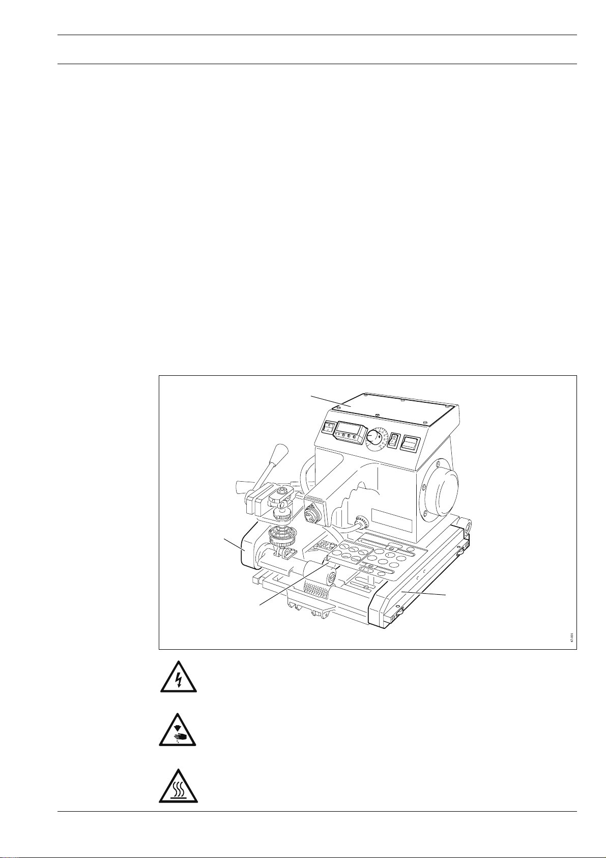
1.06 Danger
Fig. 1 - 01
1
2
3
4
Before opening the cover 1 always disconnect the plug from the mains!
Danger of injury from electric voltage!
Never operate the machine without chain guards 2 and 3!
Danger of injury due to the rotating chain!
After use always let the machine cool down first!
Danger of burns from the hot surface of hot wedge 4!
1 - 3
Page 8

Proper use
2 Proper use
The PFAFF 8362 is a heating-wedge manual heat-sealing machine with self-drive.
The machine manufactures overlapping heat-seals, with or without a test channel, on
plastics suitable for this purpose (thermoplastics), such as truck awnings, pool covers, roof
and building insulations etc.
The machine must not be operated outdoors!
Any and all uses of this machine which have not been approved of by the
manufacturer are considered to be inappropriate! The manufacturer cannot be
held liable for any damage caused by the inappropriate use of the machine! The
appropriate use of the machine includes the observance of all operational,
adjustment, maintenance and repair measures required by the manufacturer!
2 - 1
Page 9

3 Specifications
Models:
8362 -004 .................................................................................................... Standard model
8362 -045 ...................... Higher heat-sealing performance compared to the standard model
Dimensions and weight:
Length: ....................................................................................................... approx. 400 mm
Width:.........................................................................................................approx. 300 mm
Height:........................................................................................................ approx. 260 mm
Weight:............................................................................................................. approx. 9 kg
Power supply:
set for: .............................................................................. 230 V ± 10%, 50/60 Hz, 1 Phase
can be reconnected to: ................................................................................ 115 AC, L/N/PE
Power consumption:
8362-004.................................................................................................................... 400 W
8362-045.................................................................................................................... 500 W
Heating performance: .................................................................................... 400 W / 220 V
Motor:...................................................................................................24V, 2,5 A regulated
Specifications
Heat-sealing pressure: ................................................................................................ 200 N
Heat-sealing temperature: .................................................. up to 500 °C infinitely adjustable
Max. heat-sealing speed: .................................................................................. 7.0 m/min.
Seal widths:
Overlapped seal without test channel: ............................................................... 20 - 40 mm
Overlapped seal with test channel:..................................................................... as required
Max. overlap of the workpieces: ............................................................................. 80 mm
Sealable materials: ..................................................................... ● PVC
● PE - HD
● PE - LD
● EVA
● others
Type of foil: ................................................................................ ● thermally sealable
● flexible
Sealable foil thicknesses *: ............................................................................. 0.3 - 2.5 mm
* Depending on material
3 - 1
Page 10

Disposal of the machine
4 Disposal of the machine
● The proper disposal of the machine is the responsibility of the customer.
● The materials used on the machine are steel, aluminium, brass and various plastics.
The electrical equipment consists of plastics and copper.
● The machine is to be disposed of in accordance with the locally valid environmental
protection regulations.
Special care is to be taken that parts soiled with lubricants be separately
disposed of in accordance with the locally valid environmental protection
regulations!
4 - 1
Page 11

Transport packaging and storage
5 Transport packaging and storage
5.01 Transport to the customer’s premises
Within Germany, the machine is delivered without packaging. Machines are packaged for
export.
5.02 Transport within the customer’s premises
The manufacturer carries no liability for transport within the customer’s premises or to other
locations where it is to be used.
5.03 Disposal of the packaging
The packaging of these machines consists of paper, cardboard and VCE fibre.
The proper disposal of the packaging is the responsibility of the customer.
5.04 Storage
The machine can be stored for up to 6 months if not in use. During this time it should be
protected from dust and moisture.
For longer storage the individual parts of the machine, especially the moving parts, should
be protected against corrosion e.g. by a film of oil.
5 - 1
Page 12

Explanation of the symbols
6 Explanation of the symbols
In the following section of this Instruction manual, certain tasks or important pieces of
information are accentuated by symbols. The symbols used have the following meanings:
Note, information
Clean, care
Lubrication, greasing, oiling
Servicing, repair, adjustment, maintenance
6 - 1
Page 13
7 Controls
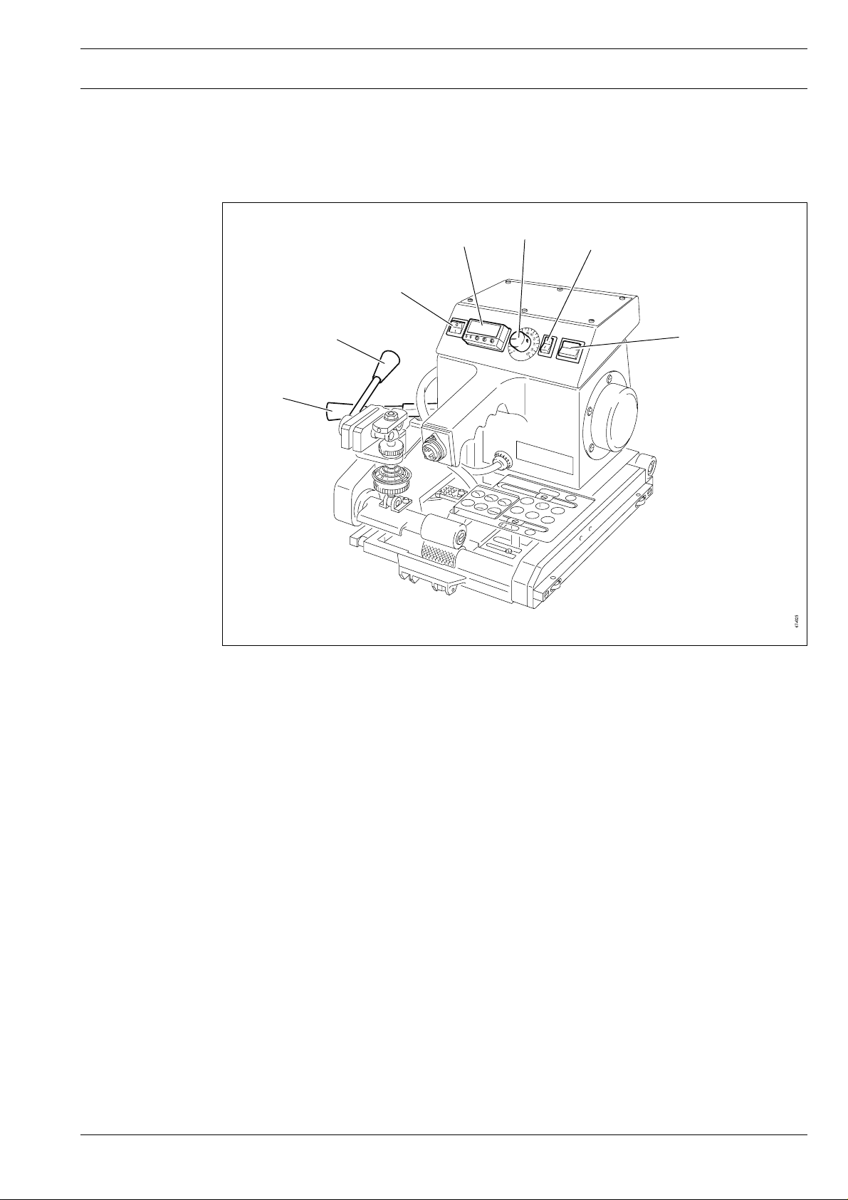
7.01 Summary of the control elements
Controls
Fig. 7 - 01
2
3
4
1
7
5
6
1. Mains switch, see Chapter 7.02.
2. Microprocessor controller for the heat-sealing temperature, see Chapter 7.03.
3. Controller for the heat-sealing speed, see Chapter 7.04.
4. Selection switch for the operating mode, see Chapter 7.05.
5. Selection switch for the operating direction, see Chapter 7.06.
6. Lever for engaging the hot wedge, see Chapter 7.07.
7. Lever for lowering the top feed roller, see Chapter 7.08.
7 - 1
Page 14
Controls
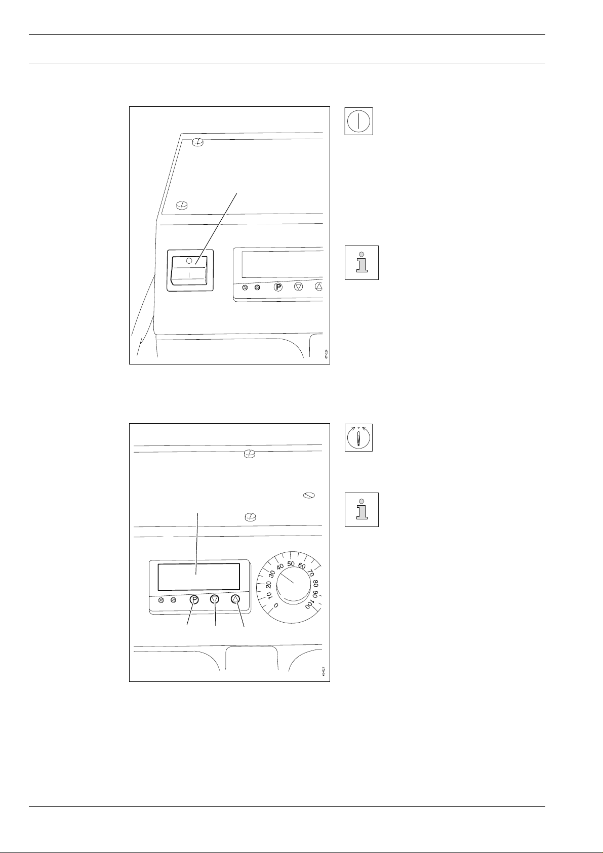
7.02 Mains switch
By pressing the mains switch 1
the machine is switched on or
off.
Position "
1
Fig. 7 - 02
Position "
7.03 Controller for the heat-sealing temperature
00
0" : Machine is switched off
00
11
1" : Machine is switched on
11
When switching off the
machine, please observe the
notes in Chapter 8.02
Switching the machine on/
off!
After pressing button 1 the heatsealing temperature can be
reduced with button 2 or
increased with button 3.
Fig. 7 - 03
4
1
The actual temperature of the hot
wedge is shown on display 4.
23
7 - 2
Page 15

7.04 Controller for the heat-sealing speed
1
Controls
● The heat-sealing speed can be altered by
turning controller 1.
Fig. 7 - 04
7.05 Selection switch for the operating mode
Position "0": Feed rollers start after the hot
Position "1": Feed rollers run constantly
The operating mode can be
selected by pressing switch 1.
wedge has been engaged
Fig. 7 - 05
1
7 - 3
Page 16

Controls
7.06 Selection switch for the operating direction
● The operating direction of the feed rollers
can be selected by pressing switch 1.
Top position:
1
Feed rollers run forwards (for
heat sealing)
Middle position:
Feed rollers are standing still
Bottom position:
Feed rollers run backwards (for
grinding in the hot wedge)
Fig. 7 - 06
7.07 Lever for engaging the hot wedge
1
● The hot wedge can be engaged and
disengaged with lever 1.
When disengaging the hot
wedge, take care to see that
lever 1
The adjacent illustration shows
the standard machine version
(PFAFF 8362-004).
clicks into position.
7 - 4
Fig. 7 - 07
Page 17

7.08 Lever for lowering the feed roller
1
2
Controls
● Lever 1 is used to lower and raise the top
feed roller 2.
The adjacent illustration shows
the standard machine version
(PFAFF 8362-004).
Fig. 7 - 08
7 - 5
Page 18

Commissioning the machine
8 Commissioning the machine
This machine must only be commissioned by qualified specialists!
All relevant safety regulations are to be adhered to!
Before starting the machine for the first time, inspect the entire heat-sealing
machine for transport damage. If damage is apparent, inform the transport
company and your PFAFF agent.
8.01 Connecting the machine to the power supply
2
● Check if the machine can be operated
with available voltage (see chapter 3
Specifications).
● Insert plug 1 of the connection cord into
the bushing of the machine and tighten
coupling ring 2.
● Plug the mains plug of the connecting
cord into the main power supply.
Fig. 8 - 01
1
8 - 1
Page 19

8.02 Switching the machine on/off
Commissioning the machine
To switch the machine on
move switch 1 to position "1".
1
Fig. 8 - 02
To switch the machine off
move switch 1 to position "0".
Danger of burns from the hot
wedge!
Immediately after the machine
has been switched off, the hot
wedge is still hot!
8 - 2
Page 20

Preparation
9 Preparation
9.01 Seal types
All Preparation work must only be carried out by appropriately trained persons!
The machine is to be separated from the power supply at the on/off switch or
by pulling the plug out of the socket whenever carrying out preparation work!
Always allow the machine to cool down before all preparation work!
Danger of burning!
Fig. 9 - 01
Seal without
test channel
On seals with a test channel, the density of the seal can be ascertained as
described in chapter 10.06.02 Testing the seal density.
Seal with
test channel
9 - 1
Page 21

02 Replacing the feed rollers
9.
The feed rollers must be changed in accordance with the material, the thickness of the foil
and the type of seal desired.
The following chart serves as an orientation aid:
Foil material Foil thickness Lower feed-roller Upper feed-roller
PVC ( soft ) > 0.8 mm Steel cross-knurled Silicon
PE-LD < 0.8 mm Steel cross-knurled Silicon
PE-LD > 0.8 mm Steel cross-knurled Steel cross-knurled
PE-HD < 0.8 mm Steel cross-knurled Silicon
PE-HD > 0.8 mm Steel cross-knurled Steel cross-knurled
Preparation
If required:
● Loosen screw 1.
● Replace the upper feed-roller 2 to suit the
seal type as described in the above chart.
● Tighten screw 1.
3
Fig. 9 - 02
If required:
● Loosen the retaining screw of the lower
2
feed-roller 3.
● Replace lower feed-roller 3 in to suit the
seal type.
● Tighten the retaining screw.
1
9 - 2
Page 22

Preparation
9.03 Adjusting the feed-roller clearance
9.03.01 Adjusting the feed-roller clearance on the PFAFF 8362-004
The feed-roller clearance is dependent on the thickness of the material of the
workpiece. The clearance is correct when one ply of the workpiece material can
just be pulled out from between the feed rollers when the upper feed-roller is
lowered.
1
● Loosen threaded pin 1.
● Adjust the feed rollers by turning the
knurled disc 2.
● Tighten threaded pin 1.
Turn the machine off!
Wait until the heating wedge is
cool! Danger of burning!
2
Fig. 9 - 03
9.03.02 Adjusting the feed-roller clearance on the PFAFF 8362-045
9 - 3
Fig. 9 - 04
Turn the machine off!
Wait until the heating wedge is
1
● Loosen screws 1.
● Adjust the feed rollers by moving the
stop bracket 2.
● Tighten screws 1.
cool! Danger of burning!
2
Page 23

9.04 Adjusting the heat-sealing pressure
The heat-sealing pressure must be set in such a way that the workpiece is
reliably fed. The feed rollers may not, however, leave pressure marks in the
material. Use a lower heat-sealing pressure for soft materials (e.g. PVC) than for
hard materials (e.g. PE).
9.04.01 Adjusting the heat-sealing pressure on the PFAFF 8362-004
Turn the machine off!
Wait until the heating wedge is
cool! Danger of burning!
● Adjust the heat-sealing pressure by
turning knurled disc 1.
1
Preparation
-
Fig. 9 - 05
+
9.04.02 Adjusting the heat-sealing pressure on the PFAFF 8362-045
Turn the machine off!
Wait until the heating wedge is
1
2
3
● Dismount spring 1.
● Loosen nut 2.
● Adjust the heat-sealing pressure by
turning tapped bush 3.
● Tighten nut 2.
● Mount spring 1.
cool! Danger of burning!
Fig. 9 - 06
9 - 4
Page 24

Preparation
9.05 Adjusting the clearance between the heating wedge and the feed rollers
With the heating wedge swung in and the feed roller lowered, there must be a clearance
between the heating wedge and the feed rollers which corresponds to the thickness of the
material.
PFAFF 8362-004
Heating wedge concave
(for thin materials)
Fig. 9 - 07
PFAFF 8362-045
Heating wedge convex
(for thick materials)
9.05.01 Adjusting the heating-wedge clearance on the PFAFF 8362-004
Turn the machine off!
Wait until the heating wedge is
cool! Danger of burning!
9 - 5
1
● Loosen screw 1.
● Move the heating wedge 2 in accordance
with the material thickness.
● Tighten screw 1.
2
Fig. 9 - 08
Page 25

Preparation
9.05.02 Adjusting the heating-wedge clearance on the PFAFF 8362-045
● Loosen nut 1.
● By turning stop screw 2, adjust the
heating-wedge clearance in accordance
with the material thickness.
● Tighten nut 1.
Fig. 9 - 09
2
1
9 - 6
Page 26

Preparation
06 Adjusting the workpiece guides
9.
The setting of the workpiece guides determines how much the workpieces
overlap.
The width of the overlap can be the same size or larger than the seal width.
Overlap width
Fig. 9 - 10
9.06.01 Adjusting the upper rear workpiece guide
1
1
2
Turn the machine off!
Wait until the heating wedge is
cool! Danger of burning!
● Loosen screws 1.
● Move workpiece guide 2 parallel to the
direction of sealing.
● Tighten screws 1.
9 - 7
Fig. 9 - 11
Page 27

9.
06.02 Adjusting the lower rear workpiece guide
1
Preparation
Turn the machine off!
Wait until the heating wedge is
cool! Danger of burning!
● Loosen screws 1 (2 screws).
● Move workpiece guide 2 parallel to the
direction of sealing.
● Tighten screws 1.
2
Fig. 9 - 12
1
9.06.03 Adjusting the front workpiece guides
4
Turn the machine off!
● Loosen screw 1.
● Move workpiece guide 2 so that it is
flush with the upper rear workpiece
guide.
● Tighten screw 1.
● Loosen screw 3.
● Move guide 4 in such a way that it is
flush with the lower rear workpiece
guide.
● Tighten screw 3.
3
Fig. 9 - 13
2
1
9 - 8
Page 28

Preparation
9.07 Adjusting the heat-sealing temperature and speed
All machine settings are determined by the workpiece which is to be sealed.
The perfect sealing temperature and speed are to be found by making a test
seal.
6
5
4
Fig. 9 - 14
● After pressing button 1 the heat-sealing temperature can be altered with keys 2 and 3.
The value set for the heat-sealing temperature appears on the display.
Button 2: Reduce the heat-sealing temperature
Button 3: Increase the heat-sealing temperature
● After the desired heat-sealing temperature has been entered, the actual temperature of
the hot wedge appears on the display again.
The LED "K2" 4 lights up, when power is fed to the hot wedge. If the difference
between the set heat-sealing temperature and the actual temperature of the
hot wedge is too great, LED "K1" 5
hooter sounds in addition.
● Adjust the heat-sealing speed by turning controller 6.
123
lights up. If the hot wedge is engaged, a
9 - 9
Page 29

10 Heat sealing
The machine must only be operated by appropriately trained personnel! The
operating personnel is also responsible for ensuring that only authorized
personnel are allowed into the area of potential danger around the machine!
10.01 The heat-sealing principle
The two workpieces which are to be connected are heated into a semi-liquid state in the area
of the seal by being brought into contact with an electrically warmed heating wedge. The
heated, semi-liquid material in the area of the seal is then pressed between the feed rollers
and thus, sealed.
To achieve a perfect heat seal, certain prerequisites must be fulfilled with regard to the
material and the machine settings.
The material to be processed must:
● be sealable (thermoplastic),
● have a thickness and characteristics which are suitable for processing with the machine,
● be clean in the area of the seal.
Heat sealing
The basic prerequisites with regard to the heat-sealing machine are:
● form and position of the heating wedge
● correct working temperature of the workpiece
● selection of the correct feed rollers
● correct pressure of the feed rollers on the workpiece
● correct clearance between the feed rollers (penetration depth) and
● correct heat-sealing speed.
All settings of the heat-sealing
machine are dependent on the
workpiece to be sealed. The
perfect settings must be
established by sealing a test
seal.
When sealing, the roller on the
back of the machine must be
swung in (see arrow)!
Fig. 10 - 01
10 - 1
Page 30

Heat sealing
10.02 Inserting the workpiece
1
2
3
Fig. 10 - 02
● Raise top feed roller with lever 1.
● Slide the lower workpiece 2 as far as it will go into the lower feed guide.
● Slide the upper workpiece 3 as far as it will go into the upper feed guide.
● Guide the beginning of the workpiece between the feed rollers.
10 - 2
Page 31

10.03 Aligning the workpieces
Heat sealing
Fig. 10 - 03
Fig. 10 - 05
Fig. 10 - 04
Fig. 10 - 06
When aligning the workpieces on the sealing surface, take care to ensure that they overlap a
little more than the overlap setting (Fig. 10-03 and Fig. 10-04).
The position of the workpieces will then be corrected by the feed guides as the material is
fed into the heat-sealing machine.
Widths of material, which are too far apart or which have too many ripples (see
Fig. 10.05 and Fig. 10.06) cannot be properly joined by the workpiece guide
units, so that they cannot be sealed properly.
10 - 3
Page 32

Heat sealing
10.04 Heat-sealing the workpieces
10.04.01 Guiding the machine manually
1
2
Fig. 10 - 07
● Connect the machine to the power supply (see chapter 8.01 Connecting the machine to
the power supply).
● Set operating mode "0", see Chapter 7.05 Selection switch for the operating mode.
In operating mode "1" the feed rollers start as soon as the machine is switched
on at the mains switch.
● Switch the machine on at the mains switch, see Chapter 7.02 Mains switch.
● Set the operating direction at forwards, see Chapter 7.06 Selection switch for the
operating direction.
● Adjust the heat-sealing temperature and speed, see Chapter 9.07 Adjusting the heatsealing temperature and speed.
To avoid damage to the material the following steps must be carried out in
quick succession after the pre-selected heat-sealing temperature has been
reached.
● Align and insert the material strips as described in the preceding chapters
● Lower the feed roller with lever 1.
● Engage the hot wedge with lever 2 (the feed rollers start).
10 - 4
During the heat-sealing process the machine must always be operated by hand.
Page 33

10.04.02 Heat-sealing with a guide
Roof battens, rectangular tubes etc. can be used to make a guide.
Heat sealing
Fig. 10 - 08
10.05 Stopping the machine
● Disengage the hot wedge (the feed rollers stop), see Chapter 7.07 Lever for engaging
the hot wedge.
● Raise the feed roller, see Chapter 7.08 Lever for lowering the feed roller.
● Switch off the machine at the mains switch, see Chapter 7.02 Mains switch.
● Pull out the mains switch and let the machine cool down.
10 - 5
Page 34

Heat sealing
10.06 Testing the seal
10.06.01 Testing the seal strength
10.06.02 Testing the tightness of the seal
All tests are only to be carried out on cold seals.
The seal strength (pull resistance) can only be established by a destructive test. This is done
by way of a tearing test on the workpieces which can either be done manually or with a
tension dynamometer (for finding out the seal strength more exactly).
The non-destructive test of seal tightness
can be carried out on an overlapping seal
with a test channel (see chapter 9.01 Seal
types).
This test can be carried out on PE-HD foils
with an air pressure of 2.5 to 5 bar which is
pumped into the test channel between the
two seals.
The air pressure can drop up to 20% in
10 minutes.
Fig. 10 - 09
10.07 Malfunctions during the heat-sealing operation cycle
Malfunction Cause/correction
Display "1999" Broken sensor or line, change the hot wedge, see
10 - 6
Chapter 11.03 Changing and grinding the hot wedge.
LED "K1" lights up Difference between the pre-selected heat-sealing
Hooter signal temperature and the actual temperature of the hot
wedge is too great, wait until the hot wedge has heated
up or cooled down sufficiently.
Page 35

11 Care and maintenance
Check cable and plug connections ...........................................................Daily before use
Clean the heating wedge ......................................................................... Daily before use
Replace the heating wedge............................................................................. As required
Replace the feed rollers .................................................................................. As required
Lubricate drive chains ..................................................................................... As required
Tension the drive chains ................................................................................. As required
11.01 Checking the cable and plug connections
Switch the machine off!
Remove the mains lead! Danger from electric voltage!
Care and maintenance
● Check cable and plug connections for damage every day before use.
Never operate a defective machine! Have the machine repaired by qualified
specialist personnel!
11.02 Cleaning the heating wedge
Ensure that the machine is
turned off and the heating
wedge is cool!
Danger of burning!
● Before operating the machine, always
remove the burn residue on the top and
bottom of the heating wedge 1 with a
soft wire brush.
Fig. 11 - 01
1
11 - 1
Page 36

Care and maintenance
11.03 Changing and grinding in the hot wedge
If the heating cartridges are defective or the hot wedge is very worn down and an optimum
sealing result can no longer be achieved by adjustment, the hot wedge must be changed
and, on the PFAFF 8362-004, ground in.
11.03.01 Changing the hot wedge on the PFAFF 8362-004
1
4
2
5
2
Fig. 11 - 02
Switch off the machine!
Let the hot wedge cool down! Danger of burns!
● Pull out switch 1
● Unscrew screws 2.
● Remove workpiece guide unit 3.
● Unscrew screw 4.
● Remove hot wedge 5.
● To fit the new hot wedge 5 carry out the above work steps in reverse order.
of the hot wedge.
Fig. 11 - 03
3
11 - 2
Page 37

Care and maintenance
11.03.02 Grinding in the hot wedge (only on the PFAFF 8362-004)
The tip of the hot wedge should match the shape of the feed hopper between
the top and bottom feed roller.
During the heat-sealing operation the entire surface of the wedge tip must
touch the workpiece.
10
7
6
7
Fig. 11 - 04
5
● Fold down driving roller 5.
● Adjust the heat-sealing temperature to "0" and the heat-sealing speed to "10", see Chapter
9.07 Adjusting the heat-sealing temperature and speed.
● Set the operating mode at "0", see Chapter 7.05 Selection switch for the operating mode.
● Unscrew the top workpiece guide unit 6 (screws 7) and the bottom workpiece guide unit 8
(screws 9).
● Fit the smooth feed rollers (steel).
● Plug the machine into the mains and switch on the mains switch.
● Set the operating direction at "reverse", see Chapter 7.06 Selection switch for the
operating direction.
● Place the hot wedge directly on the rollers, see Chapter 9.05 Clearance of the hot wedge ..
● Insert emery belt (grain size 100) with the rough side facing the hot wedge (top side).
● Lower the top feed roller with lever 10.
● Engage the hot wedge and let the emery belt run through.
● Repeat the procedure with the emery band facing the bottom side of the hot wedge.
● Grind the top and bottom side of the hot wedge alternately, until the entire surface of the hot
wedge is touching the rollers.
● Re-adjust the hot wedge to the thickness of the workpiece, see Chapter 9.05 Clearance of
the hot wedge ..
● Refit the workpiece guide units.
8
9
11 - 3
Page 38

Care and maintenance
11.03.03 Replacing the heating wedge on the PFAFF 8362-045
Switch off the machine!
Allow heating wedge to cool!
Danger of burning!
1
● Knock pin 1 downwards out of its
housing (dia. 2 mm).
● Pull out the plug of the heating wedge 2
on the front of the machine.
● Remove the cord of the heating wedge 2
from the chain cover (remove the plate in
the chain cover).
● Pull heating wedge 2 sideways out of its
mounting.
● To mount the new heating-wedge, carry
out the above steps in reverse order.
Fig. 11 - 05
2
11 - 4
Page 39

11.04 Replacing the fuse
1
Care and maintenance
2
Fig. 11 - 06
The fuse protects the machine from serious damage in cases of overload or
short circuit.
Switch off the machine!
Remove the mains lead! Danger from electric voltage!
● Remove cover 1.
● Pull fuse holder 2 out of its mounting.
● Replace the defective fuse.
● Place fuse holder 2 into the mounting.
● Screw on cover 1.
Ensure that the reason for the disturbance has been removed before turning
the machine back on!
Fig. 11 - 07
11 - 5
Page 40

Care and maintenance
11.05 Lubricating the drive chains
How often the chains have to be oiled depends on the working conditions
(moisture, amount of dirt etc.).
2
Switch off the machine!
● Remove covers 1 and 2.
● Lubricate both sides of the drive chains.
● Screw covers 1 and 2 back on.
Only use oil with viscosity class
SAE 40 and a density of
1.06 g/cm3 at 20°C (in
accordance with DIN 8195).
We recommend PFAFF chain
oil Part no. 280-1-120 106.
1
Fig. 11 - 08
11.06 Tensioning the drive chain of the lower feed-roller
1
11 - 6
Fig. 11 - 09
● Remove the chain cover.
● Loosen screws 1 and move chain guide 2 in such a way that the drive chain can be
pushed down about 5 mm.
● Screw the chain cover back on.
2
Page 41

Care and maintenance
11.
07 Tensioning the drive chain of the upper feed-roller
The chain tensioner of this drive chain is maintenance free.
1
2
4
3
Fig. 11 - 10
● Should the slack of the chain become too large, the spring pre-tension of the chain
tensioner 1 can be increased.
To do so:
● Remove the chain cover.
● Loosen nuts 2 and 3.
● Enlarge the spring tension by turning screw 4.
● Screw the chain guard back on.
11 - 7
Page 42

Circuit diagrams
Reference list for the circuit diagram
A1 Controller for heat-sealing temperature
A2 Power unit
A3 Motor board drive unit
M1 Drive unit
H1 Hooter
B1 Sensor (heating cartridge 1)
B2 Sensor (heating cartridge 2)
E1 Heating cartridge 1
Version 31.01.00
91-211 674-95
E2 Heating cartridge 2
R1 Potentiometer (heat-sealing speed controller)
K1 Solid state relay
F1 Fuse
F2 Fuse
S1 Switch - mains
S2 Switch – operating mode drive unit
S3 Switch – hot wedge engaged
S4 Switch – operating direction drive unit
X1 Plug connection - mains
12 - 1
X2 Plug connection – heating cartridges and sensors
X10 Plug connection – heating cartridges
X11 Plug connection - sensors
X12 Plug connection - hooter
95-211 899-91 Adaptor 115 volt
Page 43

95-211 905-95
Version 06.01
Circuit diagrams
12 - 2
Page 44

PFAFF Industriesysteme
und Maschinen AG
Hans-Geiger-Str. 12 - IG Nord
D-67661 Kaiserslautern
Phone: +49 - 6301 3205 - 0
Fax: +49 - 6301 3205 1386
E-mail: info@pfaff-industrial.com
Hotlines:
Technical service: +49 - 175/2243-101
Application consultance: +49 - 175/2243-102
Spare-parts hotline: +49 - 175/2243-103
Printed in Germany
© PFAFF Industriesysteme und Maschinen AG 20 09, PFAFF is the exclusive trademark of VSM Group AB.PFAFF Industriesysteme und Maschinen AG is an authorized licensee of the PFAFF trademark.
 Loading...