

Page 1

11 8 1
11 8 3
ADJUSTMENT MANUAL
This adjustment manual applies to machines
from the following serial numbers onwards:
# 6 500 122
296-12-19 202/002
Justieranleitung engl. 01.12
Page 2

The reprinting, copying or translation of PFAFF Service Manuals, whether in whole or
in part, is only permitted with our previous authorization and with written reference to the
source.
PFAFF Industriesysteme
und Maschinen AG
Hans-Geiger-Str. 12 - IG Nord
D-67661 Kaiserslautern
Page 3

Index
Contents ..................................................................................Page
1 Adjustment ........................................................................................................................... 5
1.01 Tools, gauges and other accessories for adjusting ................................................................ 5
1.02 Abbreviations ......................................................................................................................... 5
1.03 Explanation of the symbols .................................................................................................... 5
1.04 Checking and adjusting aids ...................................................................................................6
1.05 Adjusting the basic machine .................................................................................................. 7
1.05.01 Basic position of the machine drive ....................................................................................... 7
1.05.02 Preadjusting the needle height ..............................................................................................8
1.05.03 Bottom feed neutral position .................................................................................................9
1.05.04 Neutral position of the needle feed (only on PFAFF 1181) ................................................... 10
1.05.05 Bottom feed lifting motion ................................................................................................... 11
1.05.06 Bottom feed dog height ....................................................................................................... 12
1.05.07 Feed dog motion of bottom feed dog .................................................................................. 13
1.05.08 Feeding motion of needle feed (only on PFAFF 1181) .......................................................... 14
1.05.09 Needle in needle hole center (only on PFAFF 1183) ............................................................. 15
1.05.10 Needle to needle hole centre (on PFAFF 1181) .................................................................... 16
1.05.11 Synchronous strokes of needle- and drop feed (only on PFAFF 1181) ................................. 17
1.05.12 Hook shaft bearing and toothed belt tension ....................................................................... 18
1.05.13 Hook lubrication .................................................................................................................. 19
1.05.14 Needle rise, hook-to-needle clearance, needle height and
bobbin case position fi nger
..............................................................................................20
1.05.15 Thread check spring and slack thread regulator ................................................................... 21
1.05.16 Position of knee lever ...........................................................................................................22
1.05.17 Knee lever stop .................................................................................................................... 23
1.05.18 Bobbin winder ...................................................................................................................... 24
1.05.19 Limiting the stitch length ..................................................................................................... 25
1.05.20 Presser foot pressure .......................................................................................................... 26
1.05.21 Modifying the needle bar stroke .......................................................................................... 27
1.06 Adjusting the edge trimmer -731/01 .................................................................................... 28
1.06.01 Zero position of the knife ..................................................................................................... 28
1.06.02 Cutting motion ..................................................................................................................... 29
1.06.03 Knife height ..........................................................................................................................30
1.06.04 Cutting angle of the knife ..................................................................................................... 31
1.06.05 Knife position in sewing direction ........................................................................................ 32
1.06.06 Knife position crosswise to sewing direction....................................................................... 33
1.07 Adjusting the thread trimming device -900/24 ..................................................................... 34
1.0.01 Adjusting the solenoid / preliminary adjustment of the control cam ................................... 34
3
Page 4

Index
Contents ..................................................................................Page
1.07.02 Lateral alignment of the thread catcher ............................................................................... 35
1.07.03 Knife position ....................................................................................................................... 36
1.07.04 Front point of reversal of the thread catcher ........................................................................37
1.07.05 Manual trimming check ........................................................................................................38
1.07.06 Needle thread tension release ............................................................................................. 39
1.07.07 Readjusting the control cam ................................................................................................ 40
1.08 Adjusting the automatic presser foot lift -910/06 ................................................................ 41
1.09 Adjusting the back-tacking mechanism –911/37 .................................................................. 42
1.10 Basic position of the machine drive unit ............................................................................. 43
1.10.01 On machines with EcoDrive and control unit P40 ED ......................................................... 43
1.10.02 On machines with PicoDrive and control unit P40 PD2 ....................................................... 43
1.10.03 On machines with control unit MD-4-95-220-CE ................................................................. 44
4
Page 5

Adjustment
1 Adjustment
On the PFAFF 1181 and 1183 do not use a screw clamp on the needle bar! The
special coating of the needle bar could be damaged.
Please observe all notes from Chapter 1 Safety of the instruction manual! In
particular care must be taken to see that all protective devices are refi tted
properly after adjustment, see Chapter 1.06 Danger warnings of the instruction
manual!
If not otherwise stated, the machine must be disconnected from the electrical
power supply.
Danger of injury due to unintentional starting of the machine!
Notes on adjustment
All following adjustments are based on a fully assembled machine and may only be carried
out by expert staff trained for this purpose. Machine covers, which have to be removed and
replaced to carry out checks and adjustments, are not mentioned in the text.
The order of the following chapters corresponds to the most logical work sequence for machines which have to be completely adjusted. If only specifi c individual work steps are
carried out, both the preceding and following chapters must be observed.
Screws, nuts indicated in brackets ( ) are fastenings for machine parts, which must be loosened before adjustment and tightened again afterwards.
1.01 Tools, gauges and other accessories for adjusting
● 1 set of screwdrivers with blade widths from 2 to 10 mm
● 1 set of wrenches with jaw widths from 7 to 14 mm
● 1 set of Allan keys from 1.5 to 6 mm
● 1 metal rule, (Part No. 08-880 218-00)
● 1 feed dog adjustment gauge, Part No. 61-111 639-71
● 1 adjustment pin (5 mm dia.), Part No. 13-033 346-05
● Adjustment gauge, part No. 61-111 639-73
● 1 adjustment gauge for tightening the hook drive belt, Part-No. 61-111 639-76
1.02 Abbreviations
TDC = top dead center
BDC = bottom dead center
1.03 Explanation of the symbols
In this adjustment manual, symbols emphasize operations to be carried out or important information. The symbols used have the following meaning:
Note, information
Service, repair, adjustment, maintenance
(work to be carried out by qualifi ed staff only)
5
Page 6
Adjustment
1
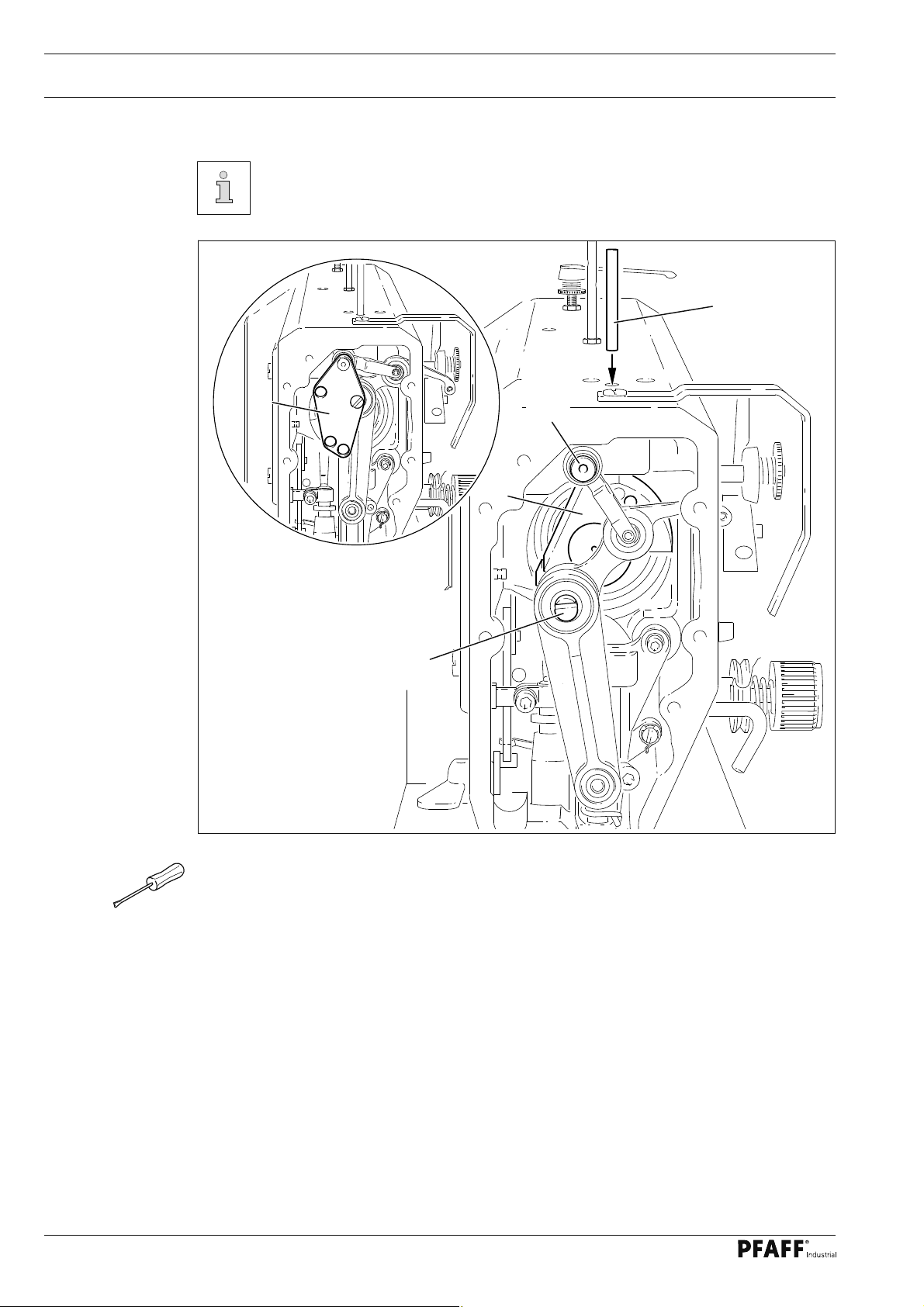
.04 Checking and adjusting aids
With the aid of blocking pin 1 (part No. 13-033346-05) and if necessary adjustment gauge 3 (part No. 61-111 639-73) the machine can be blocked in the follo-
wing positions for adjustment
1
Fig. 1 - 01
3
4
2
5
Needle bar position 1.8 mm past b.d.c.
● Turn balance wheel until needle bar is roughly in required position
● Insert blocking pin 1 in hole
● Turn balance wheel slightly back and forth until blocking pin engages crank 2
Needle bar position 0.6 mm past t.d.c.
● Set needle bar roughly at required position
● Place adjustment gauge 3 onto pins 4 and 5, making sure right side is used
(for 30 or 36 mm needle bar stroke)
Needle bar position 0.6 mm past b.d.c.
● Set needle bar roughly at required position
● Place adjustment gauge 3 onto pins 4 and 5, making sure right side is used
(for 30 or 36 mm needle bar stroke)
6
Page 7
Adjustment
1.05 Adjusting the basic machine
1
.05.01 Basic position of the machine drive
This adjustment is only required if toothed belt 2 has been removed.
Requirement
When the needle bar is positioned 0,6 mm past b.d.c., the markings 3 and 4 should be in
alignment..
2
1
4
3
Fig. 1 - 02
● Turn toothed belt sprocket 1 according to Requirement and push on toothed belt 2.
When installing the motor pay attention to the correct position of shaft fl ange,
shock absorber and motor fl ange!
7
Page 8
Adjustment
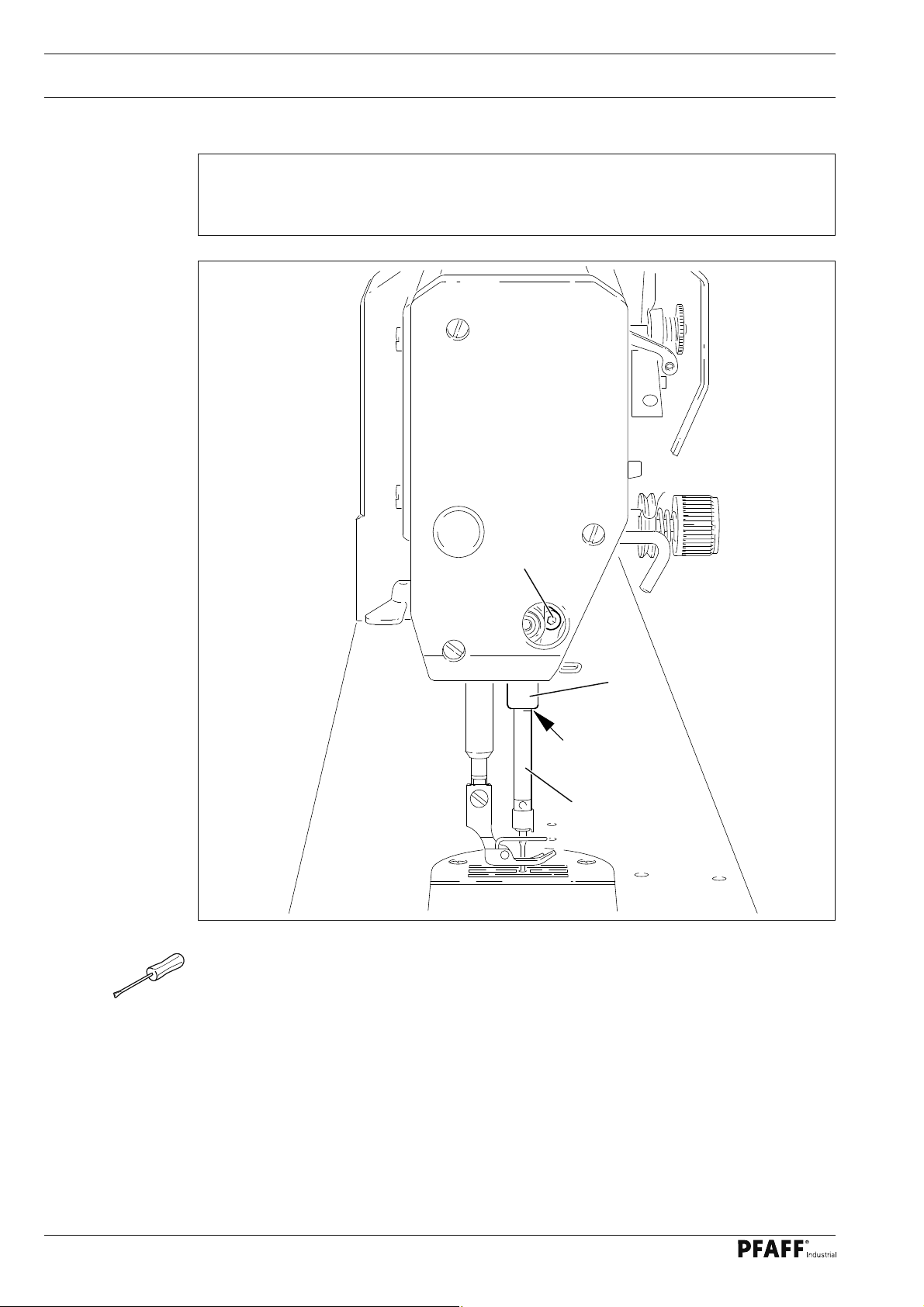
1.05.02 Preadjusting the needle height
Requirement
When the needle bar is positioned 1.8 mm above BDC, the mark on the needle bar 1
must be fl ush with the bottom edge of the needle bar frame 3.
2
3
1
Fig. 1 - 03
● Set needle bar at 1.8 mm past b.d.c. and block machine with blocking pin, see
Chapter 1.04 Checking and adjusting aids.
● Move needle bar 1 (screw 2), without turning it, according to the requirement.
8
Page 9

Adjustment
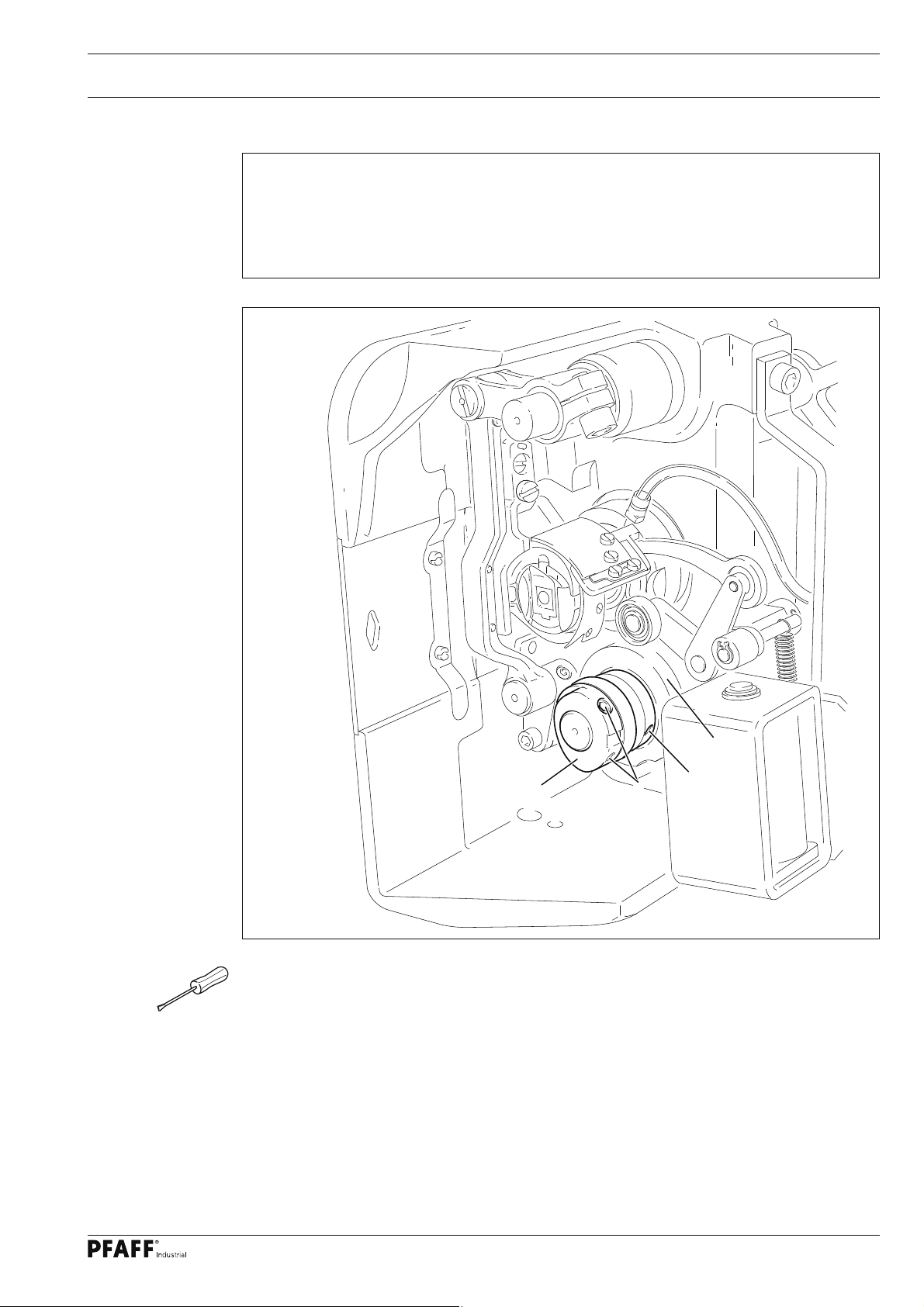
1.05.03 Bottom feed neutral position
Requirement
At stitch length setting "0", cranks 1 and 3 must be fl ush and the feed dog must not make
any feeding motion when the balance wheel is turned.
1
3
2
Fig. 1 - 04
● Raise the presser foot and set the stitch length to "0".
● Turn crank 1 (screw 2) according to the requirement.
9
Page 10
Adjustment
1.05.04 Neutral position of the needle feed (only on PFAFF 1181)
Requirement
At stitch length setting "0" the needle bar must not make any feeding motion when the
balance wheel is turned.
1
Fig. 1 - 05
● Set stitch length "0".
● Turn crank 1 (screw 2) according to Requirement.
2
10
Page 11
Adjustment
1.05.05 Bottom feed lifting motion
Requirement
At stitch length setting "0" and needle bar position 0.6 past b.d.c. on the PFAFF 1181 and
at needle bar position t.d.c. on the PFAFF 1183,
1. the bottom feed dog must be at its highest position,
2. ontrol cam 3 must rest on lifting eccentric 1.
1
Fig. 1 - 06
● Set stitch length "0" and set needle bar at required position
● Turn eccentric 1 (screws 2) according to Requirement 1.
● Adjust control cam 3 (screws 4) according to Requirement 2.
2
3
4
11
Page 12
Adjustment
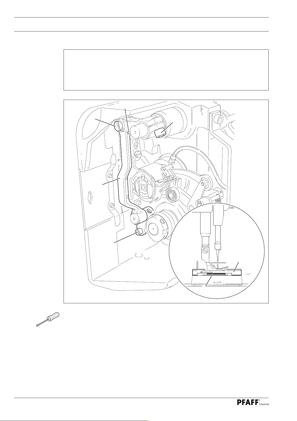
1.05.06 Bottom feed dog height
Requirement
When feed dog 1 is at its highest point at stitch length setting "0" it must
1. be centred in the feed slot crosswise and in feeding direction
2. Rest on feed dog adjustment gauge 2 over its entire length.
6
7
4
3
5
2
12
1
Fig. 1 - 7
● Set stitch length at "0" and feed dog 1 at its highest position
● Raise the presser foot.
● Place feed dog adjustment gauge 2 on the needle plate cutout with the arrow in sewing
direction so that it is fl ush with the front edge, and lower the presser foot onto it.
● Adjust feed bar 3 (screws 4) according to Requirement 1.
● Loosen screws 5 and 6.
● Adjust feed bar 3 or eccentric 7 according to Requirement 2.
● Tighten screws 5 and 6 fi rmly.
Page 13
Adjustment
1.05.07 Feed dog motion of bottom feed dog
Requirement
With the needle bar at a position 0.6 past b.d.c. on the PFAFF 1181 or in position 0.6 past
t.d.c. on the PFAFF 1183 the feed dog must not make any feeding motion when reverse-
feed lever 3 is operated at the longest stitch length setting.
3
2
1
Fig. 1 - 08
● Set the longest stitch and the needle bar at the corresponding position.
● Adjust eccentric 1 (loosen screws 2 a little) according to Requirement, but make sure it
is not moved sideways.
13
Page 14
Adjustment
1.05.08 Feeding motion of needle feed (only on PFAFF 1181)
Requirement
When the longest stitch length is set and the needle bar is positioned 0.6 mm past b.d.c.,
the needle should not move when the reverse-feed key 4 is operated..
3
1
2
4
Fig. 1 - 09
● Bring the needle bar into the position 0.6 mm past t.d.c.
● Turn eccentric 1 (screws 2) until the adjustment pin 3 locks into place.
14
Page 15

Adjustment
1.05.09 Needle in needle hole center (only on PFAFF 1183)
Requirement
The needle must penetrate the needle hole exactly in the middle.
1
4
3
2
Fig. 1 - 10
● Set the needle in the needle hole.
● Loosen screws 1, 2 and 3.
● Move the needle bar frame 4 according to the requirement.
● Tighten screw 2 and turn screw 3 slightly.
● Via screw 1, bring the retracted guide bolt to the eye of the needle bar frame 4 and
tighten it.
● Turn the handwheel a few times to prevent distortion to the needle bar frame 4.
● Tighten screw 3
15
Page 16

Adjustment
1.05.10 Needle to needle hole centre (on PFAFF 1181)
Requirement
The needle must enter excatly in the centre of the needle hole.
3
1
2
Fig. 1 - 11
● Set stitch length "0".
● Set the needle in the needle hole by turning the balance wheel
● Turn needle bar frame 1 (screws 2 and 3) according to Requirement.
16
Page 17

Adjustment
1.05.11 Synchronous strokes of needle- and drop feed (only on PFAFF 1181)
Requirement
At the longest stitch length setting the needle and feed dog must move by the same stro-
ke when the balance wheel is turned.
Fig. 1 - 12
● Set the longest stitch.
● Turn eccentric 1 (nut 2) according to Requirement .
2
1
17
Page 18

Adjustment
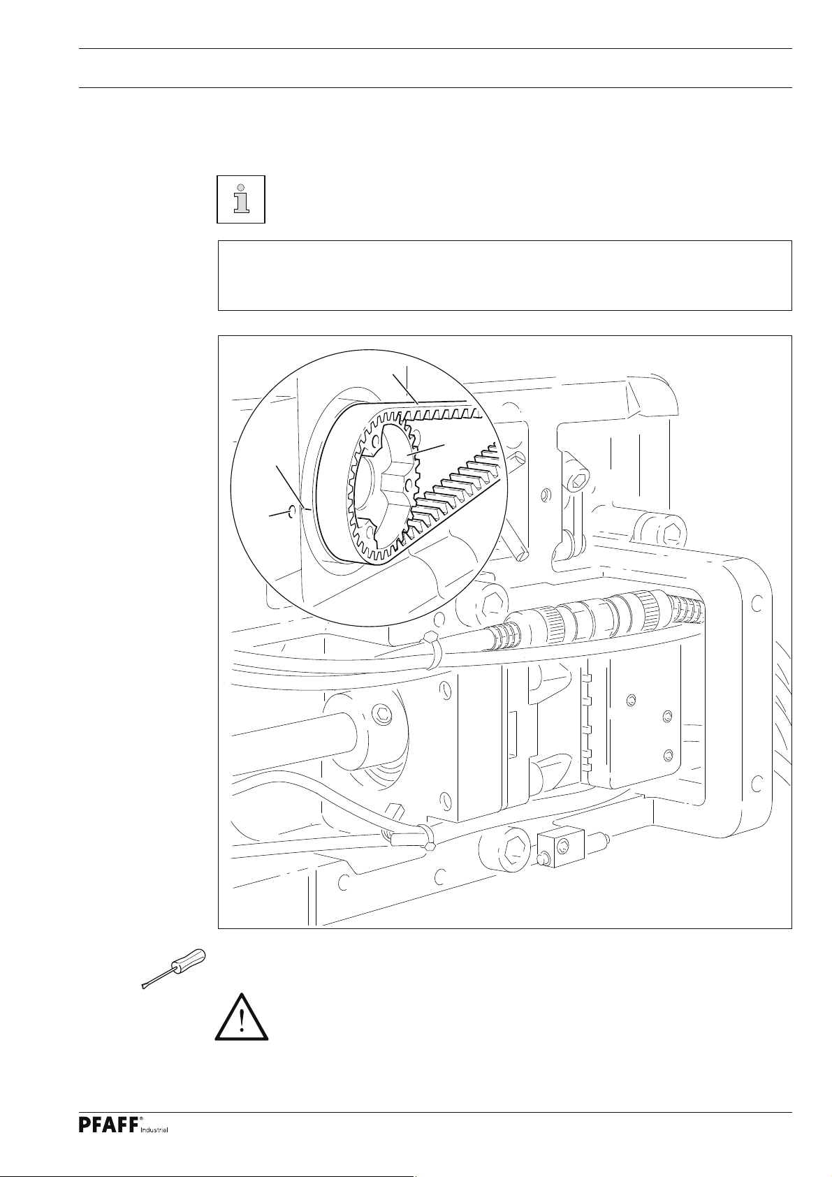
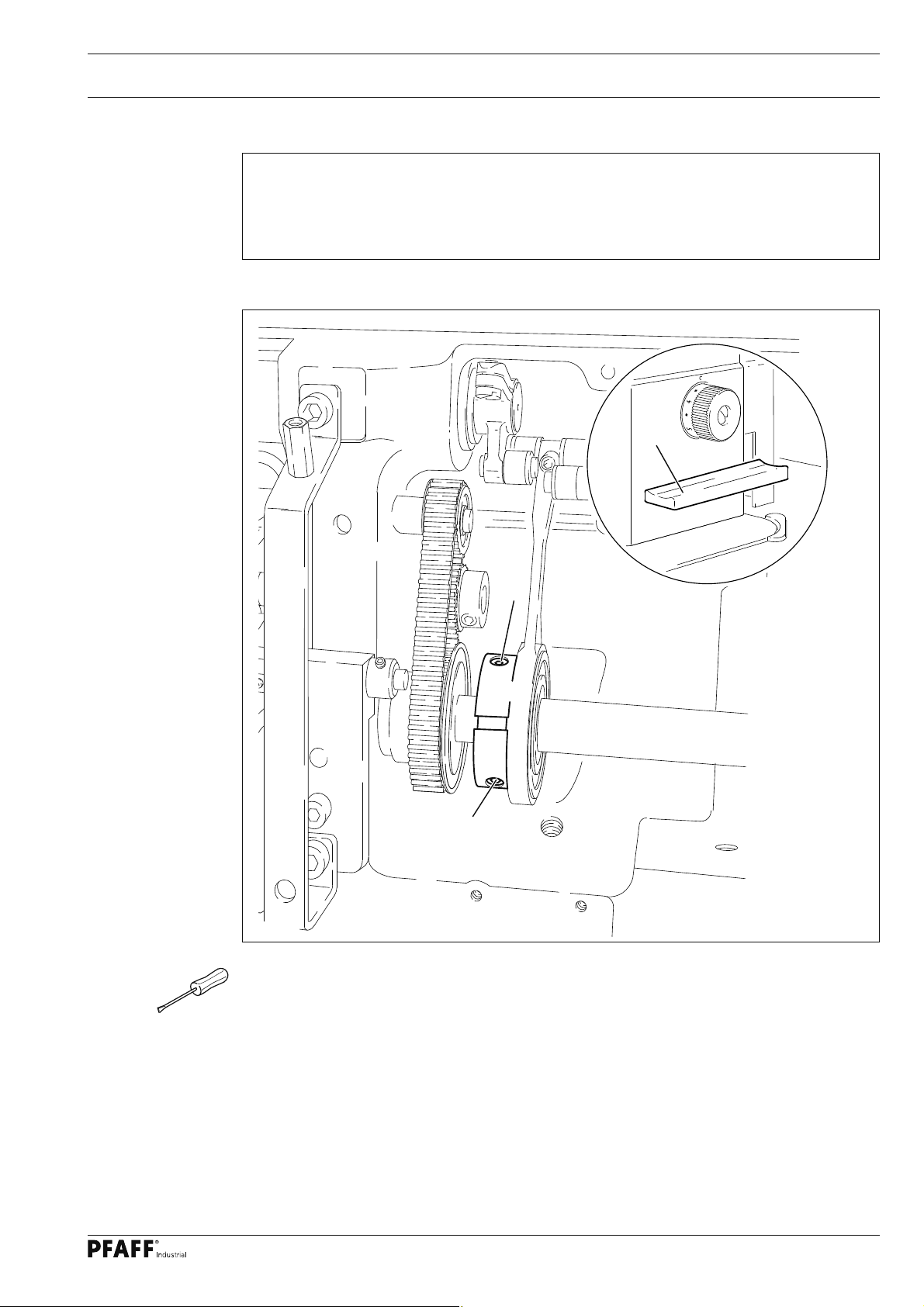
1.05.12 Hook shaft bearing and toothed belt tension
Requirement
1. The front edge of the hook shaft 6 must be at a distance of 14.5 mm to the needle
center. At the same time, the slot in the hook shaft bearing 1 (see arrow) must be parallel to the bedplate and pointing opposite to the direction of sewing.
2. The toothed belt should be tightened in such a way that, when the gauge is pushed
onto the toothed belt, the marking in the gauge window corresponds to the marking
on the bushing.
4
Fig. 1 - 13
3
2
14,5 mm
1
5
18
● Align hook shaft bearing 1 (screw 2) according to requirement 1.
● Push the gauge (Part-No. 61-111 639-76) onto the toothed belt so that it is centred to the
toothed belt and touching the bearing of the sliding shaft. The gauge window must be fa-
cing the hook.
● Eccentric 3 (screw 4) clockwise in accordance with requirement 2, taking care that the
axial position of eccentric 3 is not altered.
Page 19

Adjustment
1.05.13 Hook lubrication
Requirement
1. The centrifugal disk 1 must be positioned 1.5 mm in front of the oil ring 3.
2. When the machine is running at full speed, after approx. 10 seconds a mark should be
made by a fi ne stripe of oil on the strip of paper placed over the needle plate cutout.
3
2
1
Fig. 1 - 14
The adjustment is only necessary if the wick has been replaced.
When replacing the wick, make sure that the new wick is impregnated with oil.
● Move the centrifugal disk 1 (screw 2) according to requirement 1.
● Check requirement 2. If necessary, move centrifugal disk 1.
19
Page 20

Adjustment
1.05.14 Needle rise, hook-to-needle clearance, needle height and bobbin case position fi nger
Requirement
With the needle at 1.8 mm after BDC,
1. the hook point 6 must point to the middle of the needle and be at a distance of
0.05 mm - 0.1 mm to the clearance cut of the needle, and
2. the top edge of the needle eye must be 0.8 mm below the hook point.
3. Between the projection of the bobbin case position fi nger 4 and the bottom of the
retaining groove there should be a distance of 0.5 mm.
4
1
0,5 mm
6
3
4
0,8 mm
2
Fig. 1 - 15
● Using the adjustment pin, position the needle bar at 1.8 mm after BDC.
5
20
● Adjust the hook according to requirement 1.
● Tighten screw 1.
● Move needle bar 2 (screw 3) without turning it according to requirement 2.
● Align bobbin case position fi nger 4 (screw 5) according to requirement 3.
Page 21

Adjustment
1.05.15 Thread check spring and slack thread regulator
Requirement
1. The motion of the thread check spring must be completed when the needle point en-
ters the material (spring stroke approx. 7 mm).
2. When the thread loop is at its largest when going around the hook, the thread check
spring must have moved by approx. 1 mm.
4
-
+
3
2
Fig. 1 - 16
● Turn thread tension 1 (screw 2) according to requirement 1.
1
7 mm
● Turn thread tension 3 (screw 4) according to requirement 2.
Due to technical sewing reasons it may be necessary to deviate from the spring
stroke indicated above.
Move the slack thread regulator 3 (screw 4) toward the "+" (= more thread) or
toward the "-" (= less thread)
21
Page 22

Adjustment
1.05.16 Position of knee lever
Requirement
1. When the knee lever is in its resting position, the axle 5 must be parallel to the bedplate.
2. When the presser foot is resting on the needle plate, the presser bar lifting lever 6
must be touching the circlip 8 lightly and be at a distance of approx. 1 mm from lifting
piece 7.
1 mm
6
8
7
1
5
4
3
2
22
Fig. 1 - 17
● Lower the presser foot onto the needle plate.
● Turn shaft 1 (screws 2) according to Requirement 1.
● Turn screw 3 (nut 4) according to Requirement 2.
Page 23

Adjustment
1.05.17 Knee lever stop
Requirement
When the knee lever is fully actuated,
1. the presser foot must be raised approx. 9 mm (or approx. 13 mm for a large needle
bar stroke) above the needle plate, and
2. lever 3 must swing down automatically.
3
1
9 or 13 mm
2
Fig. 1 - 18
● Loosen nut 1 and unscrew screw 2 a few turns.
● Raise the presser foot and slide a 9 mm (for small needle bar stroke) or 13 mm (for large
needle bar stroke) thick spacer under the presser foot.
● Swing down lever 3
● Move the knee lever until it is fully actuated. The presser foot must remain on the spacer.
● Now turn screw 2 as far as it will go.
● Turn screw 2 a half turn back and tighten nut 1.
23
Page 24

Adjustment
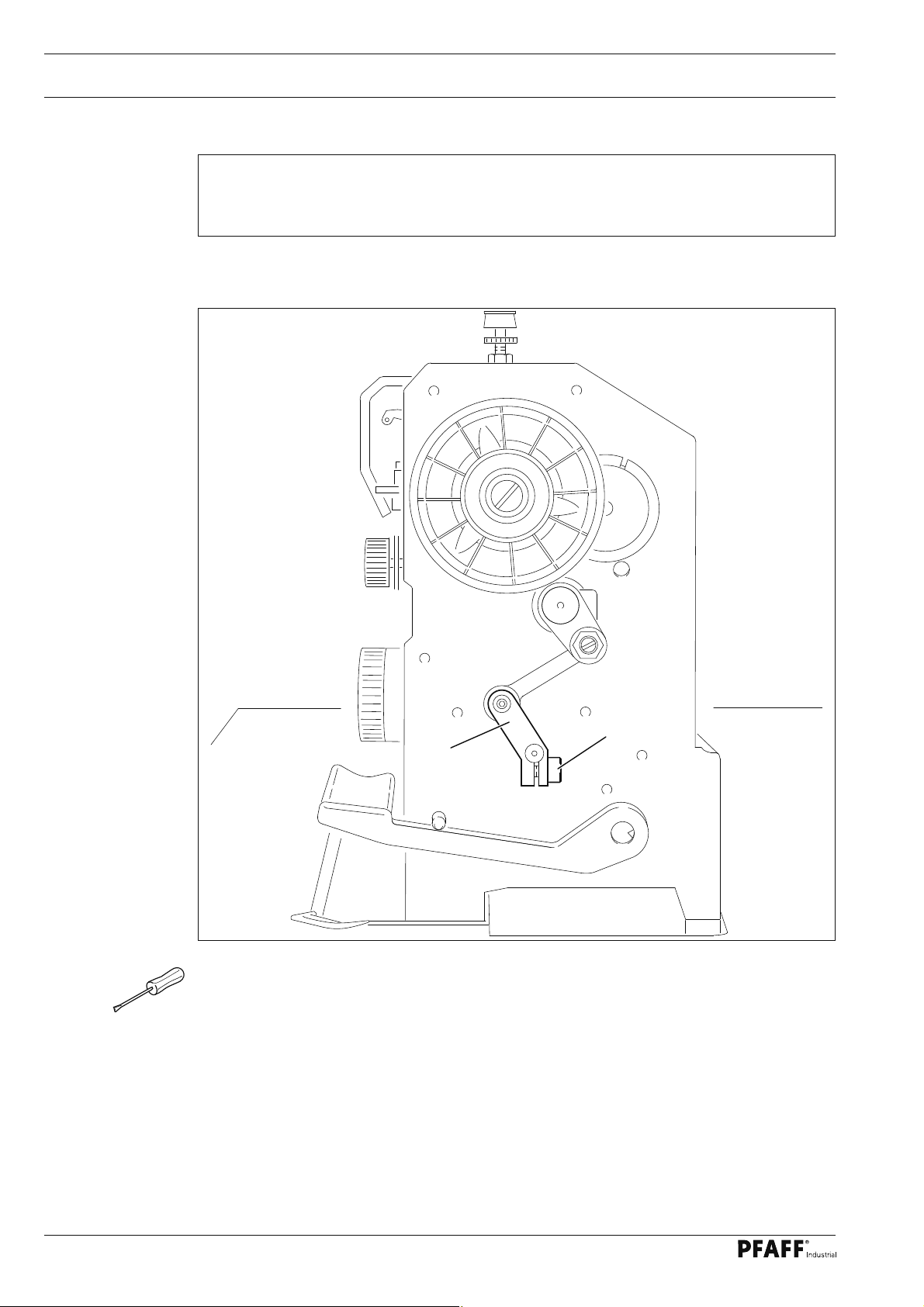
1.05.18 Bobbin winder
Requirement
1. With the bobbin winder on, the drive wheel 1 must engage reliably.
2. With the bobbin winder off, the friction wheel 5 must not be driven by the drive wheel 1.
3. The bobbin winder must turn off automatically when the thread level is approx. 1 mm
from the edge of the bobbin.
5
1
2
4
Fig. 1 - 19
● Move drive wheel 1 (screws 2) in accordance with requirement 1 and 2.
● Move bolt 3 (screw 4) in accordance with requirement 3.
3
24
Page 25

Adjustment
1.05.19 Limiting the stitch length
The maximum stitch length which can be selected can be limited mechanically.
Fig. 1 - 20
4
2
3
1
When using Version A and B part sets, the maximum adjustable stitch length
must not be larger than 3.0 or 4.5 mm (see chapter 3 Specifi cations, in the
instruction manual)!
● Set the desired maximum stitch length with regulator disk 1.
● Move crank 2 (screws 3) down against stop 4.
25
Page 26

Adjustment
1.05.20 Presser foot pressure
Requirement
The material must be fed reliably. In the process, pressure marks on the material must
not be made.
1
-
+
26
Fig. 1 - 21
● Turn screw 1 in accordance with the requirement.
Page 27

Adjustment
1.05.21 Modifying the needle bar stroke
The needle bar stroke is preset in the factory according to requirement. The
needle bar stroke can be modifi ed later if specifi c operating conditions make it
necessary to do so.
3
Fig. 1 - 22
-
+
1
2
When the needle bar stroke is altered, it is absolutely necessary to readjust the
needle height! With a 36 mm needle bar stroke, the maximum speed must be
limited to 3800 spm.
● Via the hand wheel, turn crank 1 until the screws 2 can be accessed from the side ope-
ning of the housing.
● Turn eccentric 3 (screws 2) as far as possible toward "+" (= large needle bar stroke) or to-
ward "-" (= small needle bar stroke).
● Adjust needle height (see chapter 1.05.02 Preadjusting the needle height and /or chap-
ter 1.05.14 Needle rise, hook-to-needle clearance, needle height and bobbin case po-
sition fi nger.
27
Page 28

Adjustment
1.06 Adjusting the edge trimmer -731/01
1
.06.01 Zero position of the knife
Requirement
With the edge trimmer switched off, the knife should not move when the balance wheel is
turned.
2
2
1
Fig. 1 - 23
● Turn crank 1 (screw 2) according to the requirement.
1
28
Page 29

Adjustment
1.06.02 Cutting motion
Requirement
With the edge trimmer switched on and the needle bar at its t.d.c. on the PFAFF 1183, or
at its b.d.c. on the PFAFF 1181, the knife should be at the top of its stroke.
1 2
Fig. 1 - 24
● Switch on the edge trimmer and bring the needle bar to t.d.c. or b.d.c. (see require-
ment).
● Turn eccentric 1 (two screws 2) according to the requirement.
29
Page 30

Adjustment
1.06.03 Knife height
Requirement
When the knife is at the bottom of its stroke, the front edge of the knife blade should be
approx. 0.5 mm below the top edge of the stationary knife.
0,5 mm
2
1
Fig. 1 - 25
● Switch on the edge trimmer and bring the knife to the bottom of its stroke.
● Adjust knife 1 (screws 2) according to the requirement.
30
Page 31

Adjustment
1.06.04 Cutting angle of the knife
Requirement
The knife should be
1. Touching the stationary knife 6 without counter pressure and
2. Be at a 0.1 mm slant to the stationary knife 6.
0,1 mm
6
5
3
1
2
4
Fig. 1- 26
● Loosen screws 1.
● Adjust eccentric 2 (screw 3) in accordance with the requirements.
● Tighten screws 1.
Make sure that knife guide 4 is moving smoothly!
31
Page 32

Adjustment
1.06.05 Knife position in sewing direction
Requirement
When the needle is at its b.d.c., the centre of the knife blade should be positioned at
"needle centre".
2
1
Fig. 1- 27
● Adjust knife bracket 1 (screw 2) according to the requirement.
32
Page 33

Adjustment
1.06.06 Knife position crosswise to sewing direction
Requirement
The knife should be resting on the stationary knife 3 with light pressure.
2
1
Fig. 1- 28
● Adjust knife bracket 1 (screw 2) according to the requirement.
33
Page 34

Adjustment
1.07 Adjusting the thread trimming device -900/24
1
.0.01 Adjusting the solenoid / preliminary adjustment of the control cam
Requirement
1. When solenoid 3 is completely extended, roller lever 4 should be at the lowest point
of the control cam.
2. When the needle bar is positioned at 1.8 mm after b.d.c. (needle rise position), roller
lever 4 should engage in the appropriate recess of the control cam.
4
5
6
Fig. 1 - 29
● Adjust solenoid holder 1 (screws 2) in accordance with requirement 1.
1
3
4
2
2
34
● Adjust control cam 5 (screws 6) in accordance with requirement 2.
Page 35

Adjustment
1.07.02 Lateral alignment of the thread catcher
Requirement
1. The tip of the thread catcher 5 must point exactly to the center of the needle.
2. The thread catcher 5 must be horizontal. It must not graze anything when it is
operating.
1
5
2
6
Fig. 1 - 30
● Remove knife 1 (screw 2).
● Move needle bar to its BDC.
● Loosen stop 3 (screws 4).
4
3
5
● Position thread catcher 5 (screw 6) manually in front of the needle.
● Align thread catcher 5 (screws 7) according to the requirements.
For further adjustments, leave knife 1 removed and stop 3 loosened.
35
Page 36

Adjustment
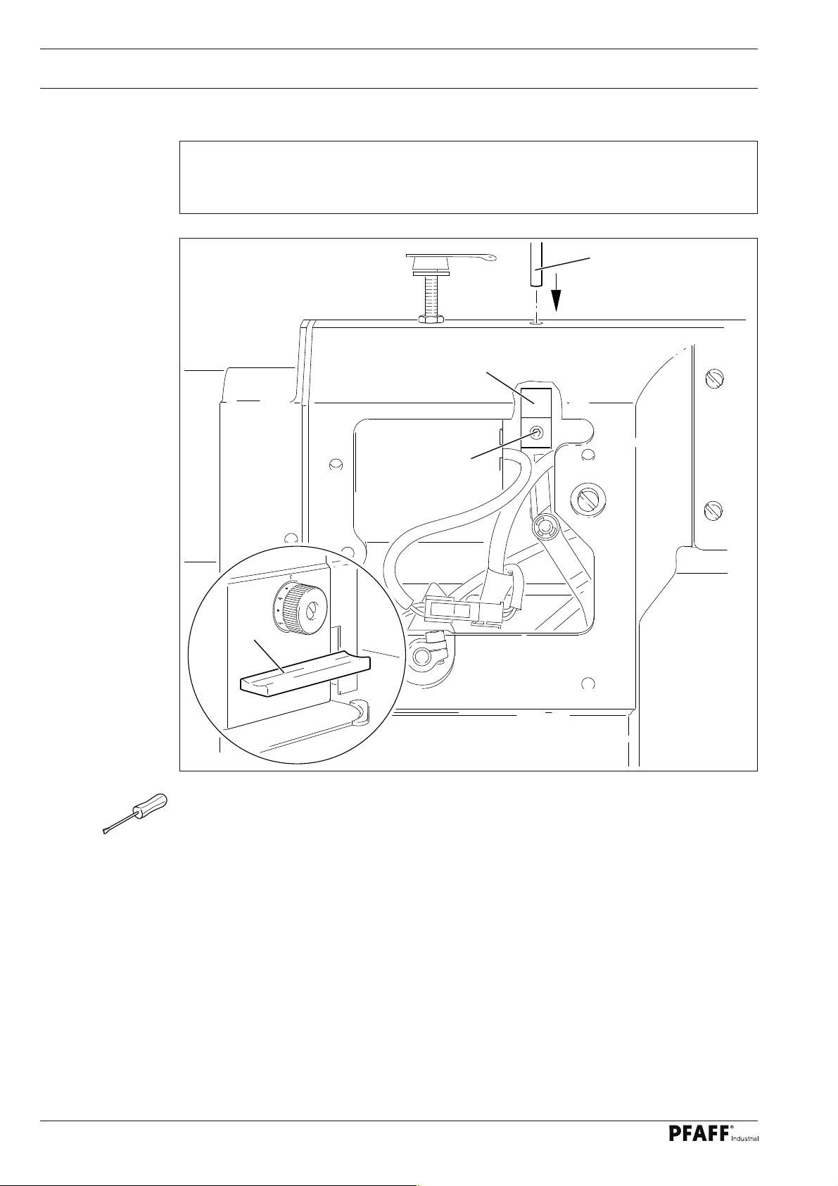
1.07.03 Knife position
Requirement
1. There must be a distance of 4 mm between the cutting edge of the knife and the
needle.
2. The right edge of the knife 1 must not extend beyond the right edge of the thread
catcher (see arrow).
Fig. 1 - 31
3
4 mm
1
1
2
36
● Bring the needle bar to BDC.
● Slide knife 1 under the locking tab and align according to requirement 1.
● Tighten screw 2 lightly.
● Adjust thread catcher carrier 3 by hand until the wedge point in the thread catcher is posi-
tioned just in front of the cutting edge of the knife.
● Align knife 1 according to requirement 2 and tighten screw 2.
Page 37

Adjustment
1.07.04 Front point of reversal of the thread catcher
Requirement
At the front point of reversal of thread catcher 4, the tip of the thread catcher cutout
should be 1 mm in front of the bobbin case position fi nger 5.
1
4
1 mm
5
Fig. 1 - 32
● Position roller lever 1 at the lowest point of the control cam.
1
2
3
● Adjust bush 2 (screws 3) according to the requirement.
37
Page 38

Adjustment
1.07.05 Manual trimming check
Requirement
Two threads must be cut perfectly both left and right in the cutout of thread catcher 1.
3
1
2
5
4
1
38
Fig. 1 - 33
● Move thread catcher 1 by hand to its front point of reversal.
● Double the thread and insert into catcher cutout.
● Carry out trimming operation manually.
● If the threads are not cut according to the requirement, align thread catcher 1 (screws 2)
with knife 3 accordingly.
● Move stop 4 against thread catcher 1 and tighten screws 5.
● Check chapter 1.07.02 Lateral alignment of the thread catcher, and readjust if necessa-
ry.
Page 39

Adjustment
1.07.06 Needle thread tension release
Requirement
1. The magnet lift should be 1.5 mm.
2. When the magnet 5 is operated by hand, there should be a distance of at least 0.5 mm
between the tension discs 6.
5
4
6
2
0,5 mm
2
3
1
Fig. 1 - 34
● Adjust disc 1 (nuts 2) according to the requirement.
● Adjust screw 3 (nut 4) according to the requirement.
39
Page 40

Adjustment
1.07.07 Readjusting the control cam
Requirement
When the take-up lever is in its t.d.c., control cam 1 should have moved thread catcher 3.
3
1
Fig. 1 - 35
● Adjust control cam 1 (screws 2) according to the requirement.
2
40
Page 41

Adjustment
1.08 Adjusting the automatic presser foot lift -910/06
Requirement
When the automatic presser foot lift is operated, the clearance between the presser foot
and the needle plate must be 9 mm for a small needle bar stroke and 13 mm for a large
needle bar stroke.
1
2
9 or 13 mm
Fig. 1 - 36
● Move magnet 1 (screw 2) according to the requirement.
41
Page 42

Adjustment
1.09 Adjusting the back-tacking mechanism –911/37
Requirement
When the longest stitch length is set, the reverse-feed control switch 3 operated and the
plunger extended, lever 1 should not touch the bed-plate..
1 2
3
Fig. 1 - 37
● Adjust lever 1 (screw 2) according to the requirement.
42
Page 43

Adjustment
1.10 Basic position of the machine drive unit
1
.10.01 On machines with EcoDrive and control unit P40 ED
● Switch on the machine.
● Press the TE/speed key twice to select the input mode.
● Select parameter "798" by pressing the corresponding +/- key, and select service level
C, see Chapter Selecting the user level in the instruction manual for the control panel.
● By pressing the corresponding +/- key select the parameter "799" (Selecting the machi-
ne class).
● Check whether value "1" is set, and correct it if necessary.
If the parameter has to be altered, operate the TE/Speed key and then switch
off the machine and switch it on again. Then select service level C again as de-
scribed above.
● By pressing the corresponding +/- key, select parameter "800" (selecting the sewing
direction).
● By pressing the corresponding +/- key, select the value for the parameter at "0".
● By pressing the corresponding +/- key, select parameter "700".
● Sew a stitch by operating the pedal.
● Turn the balance wheel in the sewing direction until the descending needle is level with
the top edge of the needle plate.
● Then check the parameter values listed in the parameter list (see Chapter
10.04 Parameter Settings) and adjust them if necessary.
● Conclude the adjustment of the sewing motor by pressing the TE/Speed key.
1.10.02 On machines with PicoDrive and control unit P40 PD2
● Switch on the machine.
● Call up the parameter input by pressing the "scroll" key.
● To switch the function keys to input (LED in the TE key lights up), press the TE key.
● By pressing the corresponding +/- keys, select parameter "798" and service level C,
see Chapter Selecting the User Level in the separate Control Panel Instruction Manual.
● Select parameter "799" by pressing the corresponding +/- keys.
● Check whether the value is set at "2" and alter if necessary.
● Switch the machine off and then on again.
● Select parameter "800" by pressing the corresponding +/- keys.
● Check whether the value is set at "0" (balance wheel turns towards the operator) and al-
ter if necessary.
● Select parameter "802" by pressing the corresponding +/- keys.
● Check whether the value is set at "0" (= no reduction ratio) and alter if necessary.
43
Page 44

Adjustment
● .By pressing the cor
responding +/- key, select parameter "700"
● Sew a stitch by operating the pedal.
● Turn the balance wheel in the sewing direction until the descending needle is level with
the top edge of the needle plate.
● Conclude the adjustment of the sewing motor by pressing the "scroll" key
1.10.03 On machines with control unit MD-4-95-220-CE
P
S
S
● Press and hold button and switch on machine.
● Parameter 47 is displayed.
● Call up input level.
● Set Code " 62" from the machine manufacturer.
● Confi rm entry and switch off machine.
● Press and hold button and switch on machine.
AB
AB
AB
D
D
S
S
S
● P
arameter 208 is displayed.
● Call up parameter
● Confi rm entry
236.
.
● Set value from the machine typ (0 = PFAFF 1183, 1 = PFAFF 1181).
● Confi rm entry and switch off machine.
● Press and hold button and switch on machine.
● Parameter 176 is displayed.
C
C
● Call up parameter 192.
D
● Press button D+ to turn function "on".
● Call up parameter 18
● Call up input lev
1.
el.
● Sew a stitch with the pedal function.
● Turn the handwheel in rotational direction until the needle point (approaching from above)
is on the upper edge of the needle plate.
A
● Confi rm entry.
44
AB
D
C
S
● Call up parameter 192.
D
● Press button D+ to turn function "off".
● Press button "S" to exit input.
Page 45

Note
Page 46

PFAFF Industriesysteme
und Maschinen AG
Hans-Geiger-Str. 12 - IG Nord
D-67661 Kaiserslautern
Phone: +49 - 6301 3205 - 0
Fax: +49 - 6301 3205 1386
E-mail: info@pfaff-industrial.com
Hotlines:
Technical service: +49 - 175/2243-101
Application consultance: +49 - 175/2243-102
Spare-parts hotline: +49 - 175/2243-103
Printed in Germany
© PFAFF Industriesysteme und Maschinen AG 2009, PFAFF is the exclusive trademark of VSM Group AB.PFAFF Industriesysteme und Maschinen AG is an authorized licensee of the PFAFF trademark.
 Loading...