

Page 1
Specifi c information
Specifi c information
Product
Product
information =
information =
specific
specific
information
information
general
general
information
information
(GB) IMPORTANT
This notice contains information and
instructions specifi c to this product
only, for complete product information,
see also the attached Petzl General
Information notice. Both notices must
be read and understood before using
this product.
(FR) IMPORTANT
Cette notice contient uniquement des
informations spécifi ques à ce produit.
Pour avoir une information complète,
voir aussi la notice des Informations
générales à tous les produits Petzl.
Les deux notices doivent être lues et
comprises ava
nt d’utiliser ce produit.
(DE) WICHTIG
Diese Gebrauchsanweisung
enthält wichtige Informationen und
Anweisungen, die nur für dieses
Produkt gelten. Weitere Informationen
zu allen Produkten fi nden Sie der
allgemeinen Petzl-Produktbeschreibung.
Vor der Verwendung dieses Produkts
müssen beide Dokumente gelesen und
inhaltlich verstanden werden.
(IT) IMPORTANTE
Questa nota informativa contiene
informazioni specifi che di questo
prodotto soltanto. Per avere
un’informazione completa, fate
riferimento anche alla nota informativa
generale di tutti i prodotti Petzl.
Entrambe le note informative vanno lette
e comprese prima di utilizzare questo
prodotto.
(ES) IMPORTANTE
Esta fi cha técnica contiene únicamente
información específi ca de este
producto. Para una información
completa, consulte también la fi cha de
Información general incluida en todos
los productos Petzl. Las dos fi chas
técnicas deben leerse y entenderse
antes de utilizar este producto.
(PT) IMPORTANTE
Esta notícia contém unicamente
informações específi cas para este
producto. Para ter uma informação
completa, veja também a notícia das
Informações Gerais para todos os
produtos Petzl. As duas notícias deve
ser lidas e compreendidas antes de
utilizar es
te produto.
(NL) BELANGRIJK
Deze bijsluiter bevat enkel de specifi eke
informatie voor dit product. Voor
een volledige informatie, zie ook de
bijsluiter met de Algemene Inlichtingen
bijgevoegd bij alle Petzl producten.
Beide bijsluiters moeten worden gelezen
en begrepen alvorens dit product te
gebruiken.
(DK) VIGTIGT
Denne brugsanvisning indeholder
specifi kke informationer og instruktioner
kun for dette produkt, for at fuldende
produktinformationen, se vedlagte Petzl
overordnende brugsanvisning. Begge
brugsanvisninger bør læse
før ibrugtagning af dette produkt.
s og forstås
(SE) VIKTIGT
Detta informationsblad innehåller
information och instruktioner som
är specifi ka för denna produkt. För
komplett produktinformation, se även
den bifogade allmänna informationen
från Petzl. Bägge informationsbladen
måste läsas och all information måste
förstås innan produkten används.
(FI) TÄRKEÄÄ
Tämä ohje käsittää tietoa ja käyttöohjeita
nimenomaan tästä tuotteesta. Lue myös
oheen liitetty, yleinen Petzl informaatio.
Molemmat ohjeet on luettava ja
ymmärrättevä ennen tuotteen käyttöä.
(NO) VIKTIG
Denne bruksanvisningen inneholder kun
informasjon og instruksjoner spesifi kt
for dette produktet. For komplett
produktinformasjon, vennligst se den
generelle bruksanvisningen fra Petzl.
Begge bruksanvisningene må leses og
forstås før produktet tas i bruk.
(RU) ВАЖНАЯ
ИНФОРМАЦИЯ
Эти материалы содержат
специальную информацию, которая
имеет отношение только к данной
продукции. Для получения полной
информации обратитесь к заметкам
содержащим Общую Информацию
Petzl (прилагается). Пожалуйста,
прочитайте и осознайте обе части
инструкции перед тем, как начнёте
использовать эту продукцию.
(CZ) DŮLEŽITÉ
Tento návod obsahuje informace, které
jsou určeny pouze pro tento výrobek.
Pro úplnější informace použijte
přiložené Všeobecné informace rmy
Petzl. Před použitím tohoto výrobku
jste povinni se seznámit s obsahem
obou dokumentů.
(PL) UWAGA
Niniejsza instrukcja zawiera wyłącznie
informacje właściwe dla tego produktu
W celu uzyskania kompletnych
informacji należy zapoznać się
instrukcją Informacje ogólne dla
wszystkich produktów Petzl. Należy
przeczytać i zrozumieć obydwie
instrukcje zanim zacznie się używać ten
produkt.
(SI) POMEMBNO
Ta navodila vsebujejo informacije,
ki se nanašajo samo na ta izdelek.
Za popolnejše informacije o izdelku
preberite tudi Splošne informacije
Petzl, ki so priložene. Pred uporabo
izdelka morate prebrati in razumeti obe
navodili.
(HU) FIGYELEM
Ez a használati utasítás kizárólag
a termékre vonatkozó speciális
információkat tartalmazza, és csak
az összes Petzl termékre vonatkozó
Általános információkkal együtt
nyújt elégséges tájékoztatást. A
termék használatbavétele előtt
elengedhetetlen a két ismertető alapos
áttanulmányozása és megértése.
(BG) ВАЖНО
Тази листовка съдържа само
специфичната информация и
указания за употреба на този
продукт. За да получите пълна
информация, вижте също
листовката ”Обща информация”
отнасяща се до всички продукти
на Петцл. Преди да започнете да
употребявате този продукт, трябва
да прочетете и разберете и двете
листовки.
(JP)重要な注意事項
ここで は 、この 製 品 特
有の注意、説明事項の
みを掲載しています。
この製品に関するその他の情
報は、製品に添付されている
一般注意事項を参照ください。
ここに ある説 明と 製 品 に 添 付さ
れている一般注意事項を必ず
よく読 み 、理解したうえで製品を
ご使用ください。
(KR) 중요
이 지시사항은 이 상품에 관한
정보와 사용 지시만을 포함하
고 있으며, 완전한 제품 정보는
부가 설명된 일반 정보를 참고
하십시오. 제품을 사용하기 전
에 반드시 두 사항을 숙지하시
기 바랍니다.
(CN) 重要声明
这段声明的内容和指示只是对
这特定的产品而言,其它产品
资料请参阅附上之一般Petzl产
品指示。在使用产品前,两方
面的指示均需阅读及充分明白
方可使用。
(TH) БХ¤ЗТБЛБТВ
¢йН¤ЗТБаµЧН¹НС¹¹ХйºГГ¨ШаГЧиН§¤Уб
¹Р¹У бЕР¢йНБЩЕ¾ФаИЙ¢Н§¼ЕФµАС³
±м¹Хй КУЛГСº¢йНБЩЕ¼ЕФµАС³±м·ХиКБºЩГ³м,
гЛй´Щ·Хи¤Уб¹Р¹У·СиЗд»¢Н§ Petzl
·ÕèṺÁÒ ¤Óá¹Ð¹Ó·Ñé§ÊͧÍѹÍѹµéͧ
Íè¹ áÅзӤÇÒÁà¢éÒ㨠¼ÅÔµÀѳ±ì¹Õé.
Activities involving the use of this product are inherently dangerous. You are
Activities involving the use of this product are inherently dangerous. You are
FAILURE TO HEED ANY OF THESE WARNINGS MAY RESULT IN SEVERE INJURY OR DEATH.
FAILURE TO HEED ANY OF THESE WARNINGS MAY RESULT IN SEVERE INJURY OR DEATH.
1
Notice P70 LASERSONIC réf. : P70500-B
WARNING
WARNING
responsible for your own actions and decisions.
responsible for your own actions and decisions.
Before using this product, you must :
Before using this product, you must :
- Read and understand all Product Information.
- Read and understand all Product Information.
- Become acquainted with the product’s capabilities and limitations.
- Become acquainted with the product’s capabilities and limitations.
- Understand and accept the risks involved.
- Understand and accept the risks involved.
Additionally, you should get qualified instruction in its proper use.
Additionally, you should get qualified instruction in its proper use.
Page 2
www.petzl.com
LASER
LASER
LASERSONIC
LASERSONIC
(EN)
Ice screw
(FR) Broches à glace
(DE)Eisschraube
(IT) Chiodo da ghiaccio
(ES) Tornillo de hielo
Nomenclature of parts
1a 1b
2
3
1. Maintenance
2. Strength - Test
4. Advice on placement
5. Removal
LASERSONIC
Made in France
3 year guarantee
Patented
S
100 mm
LASER
P71
128 g 146 g 164 g 184 g
LASERSONIC
P70
149 g 165 g 185 g 205 g
M
130 mm
0197
UIAA UIAA UIAA
100 P71 130 P71 170 P71 210
100 P70 130 P70 170 P70 210
L
170 mm
0197
XL
210 mm
0197
UIAA
3. Placement
15 kN
ICE
(UIAA
Definition)
90°
MULTIHOOK 04950
Ice Rock
0197
0197
(EN) Body controlling the manufacturing of this PPE
(FR) Organisme contrôlant la fabrication de cet EPI
(DE) Organismus der die Herstellung dieses PSA kontrolliert
(IT) Organismo che controlla la fabbricazione di questo DPI
(ES) Organismo controlador de la fabricación de este EPI
APAVE SUD EUROPE - BP193 - 13322 MARSEILLE Cedex 16
(EN) Notified body intervening for the CE type testing examination
(FR) Organisme notifié intervenant pour l’examen CE de type
(DE) Zertifikationsorganismus für CE Typen Überprüfung
(IT) Ente riconosciuto che interviene per l’esame CE del tipo
(ES) Organismo notificado que interviene en el examen CE de tipo
2
Notice P70 LASERSONIC réf. : P70500-B
UIAA
(EN) Quality label of the UIAA
(Union International des Associations
d'Alpinisme).
(FR) Label de qualité de l'union
internationale des associations d'alpinisme.
(DE) Qualitätslabel der UIAA
(Union International des Associations
d'Alpinisme).
(IT) Label di qualità dell'Unione
Internazionale delle Associazioni di
Alpinismo.
(ES) Atestado de calidad de la UIAA (Union
International des Associations d'Alpinisme).
Page 3
(GB) ENGLISH
(GB) Ice screw
Limitations on use
Petzl Charlet ice screws conform to the safety
requirements of the 89/686/CE directive on
personal protective equipment (PPE) and to the
UIAA requirements with the exception of the 100
mm versions (ice screws for direct aid only, not
intended for protection against falls from height).
Nomenclature of parts
(1a) Attachment point only,
(1b) Attachment point with integral rotating
crank, (2) Tube, (3) Drill bit.
Principal materials: chrome molybdenum steel.
Checking, points to verify
Before each use, carry out a visual check of the
condition of the ice screw. If you note any cracks,
twisting of the tube, deformation of the drill bit
or any other structural anomaly, do not use the
ice screw.
Diagram 1. Maintenance
After each use, dry out your ice screws.
Spray with a lubricant in order to prevent
corrosion and facilitate clearing of the tube.
Regularly check the sharpness of the teeth of the
drill bit and sharpen them carefully as necessary.
Use only a fi le, taking care not to modify the
geometry of the cutting edges. Sharpening is a
delicate operation, carrying the risk of noticeably
affecting the performance of your ice screws.
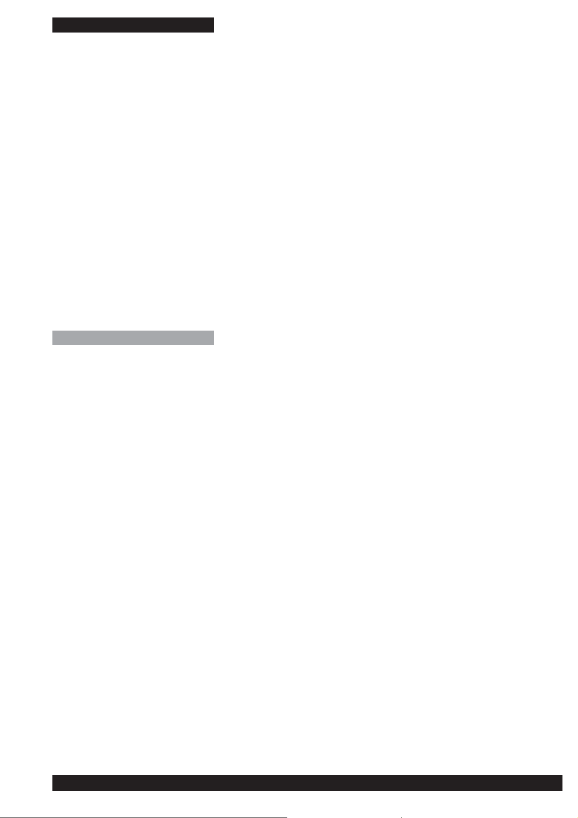
Turn the screw manually in an anticlockwise
direction. The LASER SONIC is impossible to drop
on removal as long as it remains attached to the
rope.
Remove the cylinder of ice inside the screw
(blocking the tube of the screw) by tapping the
attachment point, straightaway if possible. Never
tap on the threads as this can cause damage.
If the ice cylinder is jammed in, use the
MULTIHOOK threading tool, without scratching the
inside of the tube.
Carrying (walking in and out)
Replace the end covers after use to protect the drill
bit as well as the rest of your equipment which
could be damaged by the sharp teeth. Use of a
storage bag (e.g. FAKIR) is recommended.
Instructions for use
Diagram 2. Strength
The CE directive requires a minimum pull-out
strength of 10 kN. The UIAA requires a minimum
of 15 kN. Do not confuse the strength of the
screw under testing conditions with the holding
power of the screw under actual conditions of
use. The latter can vary according to the quality
of the ice. In general, the quality of the ice
improves with depth.
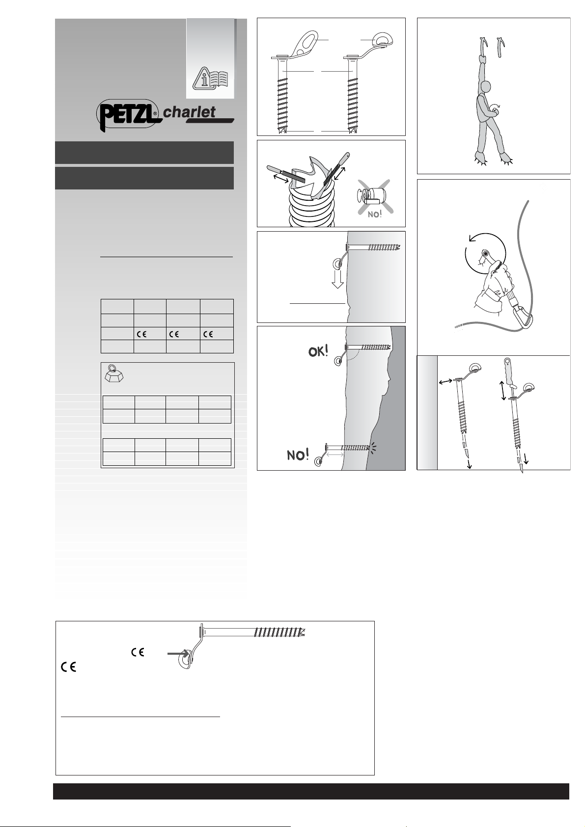
Diagram 3. Placement
Choose the thickest and most homogeneous
ice possible. Choose the length of the ice screw
according to the thickness. WARNING, do not
force if the ice screw touches the rock as this can
seriously damage the drill bit.
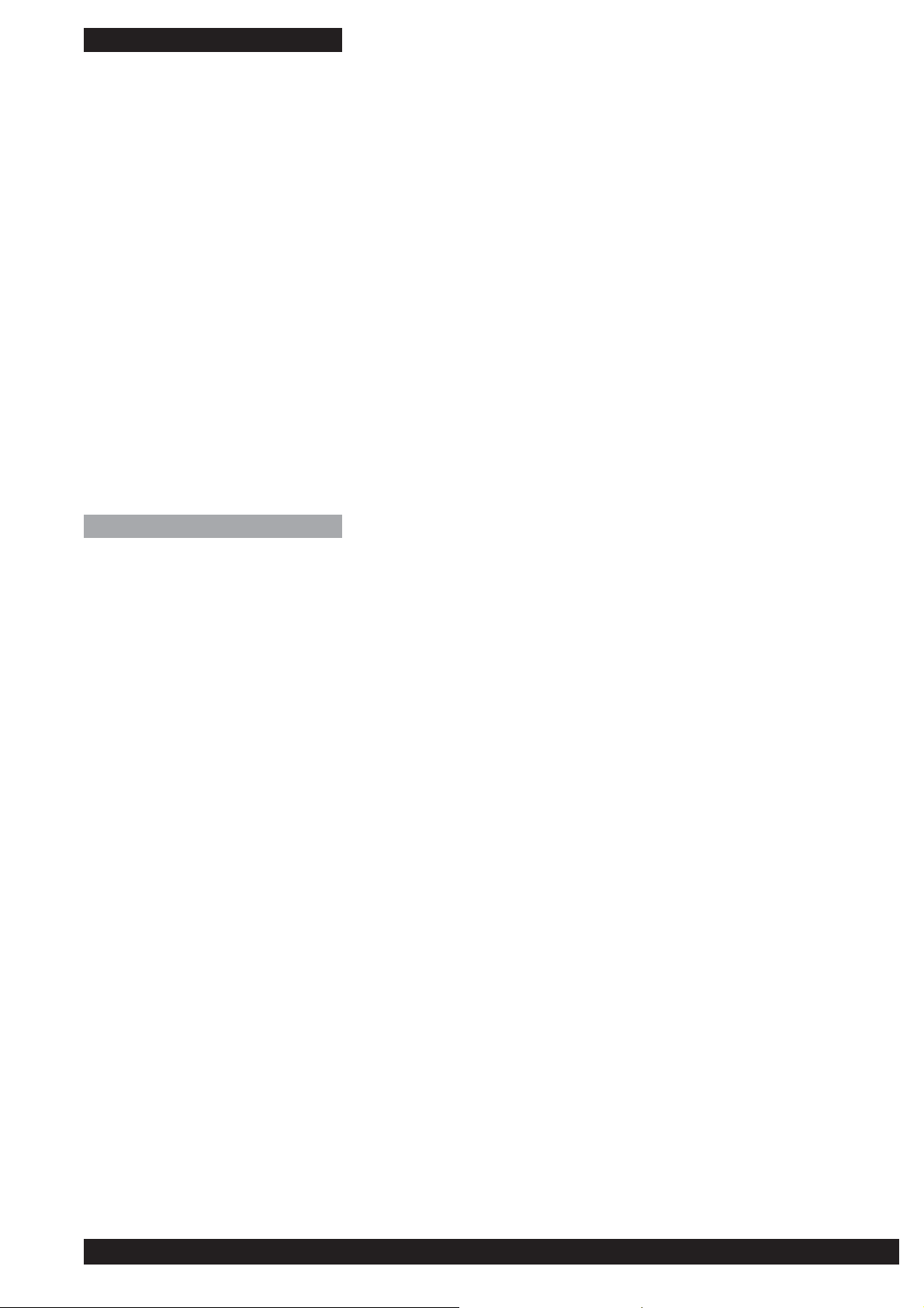
Diagram 4. Advice on placement
Clean away poor ice or unconsolidated surface
ice in order to fi nd homogeneous, solid ice.
Position yourself in order to have the elbow bent
at 90° and the hand at hip level. This is optimal
for effi cient application of force and precision.
Use the rule of three to start:
- strike three times (position of the tube at 90°),
- turn three times “there and back“, clear the tube
if necessary,
- Make three complete turns clockwise.
Screw in the ice screw completely, as far as the
attachment point, with the aid of the crank. A
continuous cylinder of ice should emerge from
the screw.
Place an ice screw immediately upon leaving the
belay to reduce the fall factor. Aim to reduce the
potential impact force on the ice screw by careful
management of the path followed by the rope.
Use a NITRO energy absorbing quickdraw to
reduce the impact force.
Our ice screws have a polished fi nish to refl ect
the solar radiation as much as possible, so
reducing heating of the metal. WARNING over a
long period of exposure to the sun’s rays (toprope anchors for example) the holding power
of the ice screw can be reduced (because of the
heating effect).
Diagram 5. Removal
3
Notice P70 LASERSONIC réf. : P70500-B
Page 4
(FR) FRANCAIS
(FR) Broche à glace
Champ d’application
Les broches à glace Petzl Charlet sont conformes
aux exigences de sécurité de la directive
89/686/CE relative aux équipements de protection
individuelle (EPI) et aux exigences UIAA à
l’exception des versions S de 100 mm de long
(broches de progression ne protégeant pas
contre les chutes de ha
uteur).
Nomenclature des pièces
(1a) Patte d’accrochage seule, (1b) Plaquette
manivelle rotative, (2) Tube, (3) Trépan.
Matériaux principaux : acier chrome molybdène.
Contrôle, points à vérifi er
Contrôlez visuellement avant chaque utilisation,
l’état de la broche. Si elle présente une fi ssure,
un tube tordu, un trépan déformé ou toute autre
anomalie structurelle, ne plus utiliser cette
broche.
Schéma 1. Entretien
Après chaque utilisation, séchez vos broches.
Pulvérisez un lubrifi ant afi n de prévenir la
corrosion et faciliter le débourrage du tube.
Vérifi ez régulièrement l’affûtage des dents du
trépan et au besoin les aiguiser soigneusement.
Utilisez exclusivement une lime en respectant
bien les angles d’attaque (ou dépouille).
L’aiguisage est une opération délicate qui risque
de modifi er sensiblement les performances de
vos broches.
Tournez manuellement en sens inverse des
aiguilles d’une montre. La broche LASER SONIC
présente l’avantage d’être imperdable au
débrochage si vous la laissez accrocher à la
corde.
Retirez la carotte de glace (qui bouche le tube de
la broche) en tapotant sur la patte, si possible
tout de suite. Ne tapez jamais sur le fi letage cela
l’endommagerait.
Si la carotte est coincée, utilisez le crochet à
lunules MULTIHOOK sans rayer l’intérieur du
tube.
Transport (marche d’approche)
Remettez les bouchons après utilisation
pour protéger le trépan ainsi que le reste de
votre matériel qui risquerait d’être perforé.
Il est conseillé d’utiliser un sac de rangement
(ex. FAKIR).
Prescriptions d’utilisation
Schéma 2. Résistance
L’exigence de la directive CE pour le test de
résistance à l’arrachement est au minimum
de 10 kN. L’exigence UIAA est au minimum de
15 kN. Ne confondez pas la résistance de la
broche dans le cadre des tests et la tenue de la
broche dans la glace sur le terrain. Celle-ci peut
varier en fonction de la qualité de la glace. En
général, la qualité de la glace s’améliore avec la
profondeur.
Schéma 3. Emplacement
Choisissez la glace la plus homogène et la plus
épaisse possible. Choisissez la longueur de la
broche en fonction de l’épaisseur. ATTENTION, ne
forcez pas si la broche touche le rocher. Cela peut
gravement endommager le trépan.
Schéma 4. Conseils pour brocher
Nettoyez la mauvaise glace ou glace de surface
non consolidée afi n de trouver la glace homogène
et solide. Placez-vous de façon à avoir le coude
plié à 90° et la main à hauteur de hanche. Vous
conservez ainsi force et précision.
Appliquez la règle des 3 pour amorcer :
- tapez 3 fois (position du tube à 90°),
- tournez 3 fois «aller et retour», nettoyez si
besoin le tube,
- faites 3 tours dans le sens des aiguilles d’une
montre.
Vissez la broche à fond jusqu’à la patte, à l’aide
de la manivelle. Une carotte de glace continue
doit sortir de la broche.
Posez une broche immédiatement au départ du
relais pour diminuer le facteur de chute. Veillez à
réduire la force de choc potentielle sur la broche
en gérant au mieux le trajet de la corde. Utilisez
une dégaine absorbeur NITRO pour diminuer la
force de choc.
Nos broches sont brillantes pour réfl échir au
maximum le rayonnement solaire et limiter
l’échauffement du métal. ATTENTION sur une
longue période d’exposition au soleil (exemple
ancrages de moulinette) la tenue de la broche
peut diminuer (à cause de l’échauffement).
Schéma 5. Débrocher
4
Notice P70 LASERSONIC réf. : P70500-B
Page 5
(DE) DEUTSCH
(DE) Eisschraube
Anwendungsbereich
Petzl Charlet Eisschrauben entsprechen den
Sicherheitsvorschriften gemäß der Richtline
89/686/CE für persönliche Schutzausrüstung
(PSA) sowie den Anforderungen der UIAA, mit
Ausnahme der 10 cm langen S Versionen (diese
Eisschrauben dienen lediglich der Fortbewegun
und schützen nicht vor Stürzen aus der Höhe).
Benennung der Teile
(1a) Einfache Lasche, (1b) Lasche mit integrierter
Kurbel, (2) Röhre, (3) Bohrzähne.
Material : Chrommolybdänstahl.
Überprüfung, zu kontrollierende Punkte
Führen Sie vor jedem Einsatz eine visuelle
Überprüfung der Eisschraube durch. Sollten
Ihnen Risse, Verformungen an der Röhre oder
den Bohrzähnen und sonstige strukturelle
Anomalien auffallen, verwenden Sie die
Eisschraube nicht.
Abbildung 1. Pfl ege
Trocknen Sie die Eisschrauben nach jeder
Verwendung. Tragen Sie ein Schmiermittel auf,
um Korrosion zu vermeiden und um die Röhre
leichter entleeren zu können.
Überprüfen Sie regelmäßig die Schärfe der
Bohrzähne und feilen Sie sie, sofern erforderlich.
Verwenden Sie ausschließlich eine Handfeile
und achten Sie darauf, die Geometrie der
Schneidkanten nicht zu verändern. Das Feilen ist
ein Vorgang, der viel Sorgfalt erfordert. Hierbei
besteht das Risiko, die Leistung der Eisschrauben
negativ zu beeinfl ussen.
durch sorgfältige Auswahl des Seilverlaufs zu
reduzieren. Mithilfe einer NITRO Expressschlinge
mit Falldämpferfunktion könne
weiter verringern.
Unsere Eisschrauben verfügen über eine polierte
Oberfl äche, um einen möglichst großen Teil
eventuell auftretender Sonneneinstrahlung zu
refl ektieren. Auf diese Weise wird die Erwärmung
de
Eis platzierte Schrauben über einen längeren
Zeitraum hinweg Sonneneinstrahlung ausgesetzt
g
(z. B. bei einem Toprope-Stand), kann dies zu
einer Verminderung der Festigkeit der Schraube
im Eis führen - sie kann ausschmelzen.
Abbildung 5. Herausdrehen
Drehen Sie die Schraube von Hand entgegen
dem Uhrzeigersinn. Die LASER SONIC kann beim
Herausdrehen nicht herunterfallen, solange Sie
am Seil befestigt bleibt.
Entfernen Sie den Eisschneezylinder in der Röhre
(der das Röhreninnere blockiert), indem Sie
möglichst sofort leicht auf die Lasche klopfen.
Klopfen Sie keinesfalls auf das Gewinde, da es
beschädigt werden könnte.
Wenn Sie den Schneezylinder auf diese Weise
nicht entfernen können, verwenden Sie das
MULTIHOOK-Werkzeug. Kratzen Sie nicht am
Inneren der Röhre.
Transport (Zustieg und Abstieg)
Setzen Sie nach Gebrauch die Schutzkappen auf,
um die Bohrzähne der Schraube und Ihr übriges
Material zu schützen, dass durch die scharfen
Zähne beschädigt werden könnte. Es ist ratsam,
einen Packbeutel zu verwenden (z. B. FAKIR).
n Sie den Fangstoß
s Metalls reduziert. ACHTUNG: Werden im
Gebrauchsanweisung
Abbildung 2. Festigkeit
Gemäß dem CE-Standard ist eine
Mindestfestigkeit von 10 kN erforderlich. Gemäß
der UIAA sind mindestens 15 kN erforderlich.
Verwechseln Sie nicht die Festigkeit einer
Eisschraube unter Testbedingungen mit der
tatsächlichen Festigkeit der Schraube unter
normalen Anwendungsbedingungen. Letztere
können Fallweise stark voneinander abweichen,
je nach Qualität des Eises. Normalerweise
verbessert sich die Eisqualität in der Tiefe.
Abbildung 3. Setzen einer Eisschraube
Wählen Sie die Länge der Eisschraube
unter Berücksichtigung der Dicke. Setzen
Sie Eisschrauben möglichst in dickes und
homogenes Eis. ACHTUNG: Versuchen Sie nicht,
eine Eisschraube mit Gewalt weiterzudrehen,
wenn diese auf Fels stößt, da hierbei die
Bohrzähne beschädigt werden können.
Abbildung 4. Weitere Hinweise zum
Setzen von Eisschrauben
Säubern Sie die Eisoberfl äche von brüchigem Eis
und sonstigen Unebenheiten, um homogenes und
solides Eis zu fi nden. Positionieren Sie sich so,
dass Sie die Schraube mit etwa 90° gebeugtem
Ellbogen auf Hüfthöhe eindrehen können.
Diese Stellung ist optimal für den effektiven
Umsatz von Kraft und Genauigkeit.
Verwenden Sie zum Starten die Dreierregel:
- Stoßen Sie drei Mal (Röhrenposition = 90°),
- Drehen Sie die Röhre drei Mal vorwärts und
rückwärts und entlehren Sie sie, falls erforderlich,
- Führen Sie drei vollständige Umdrehungen im
Uhrzeigersinn durch.
Drehen Sie die Eisschraube vollständig bis zur
Lasche in das Eis ein. Verwenden Sie hierfür eine
Kurbel. Aus der Röhre der Eisschraube sollte ein
dünner Eisschneezylinder austreten.
Setzen Sie sofort nach Verlassen des
Standplatzes eine Eisschraube, um ggf.
den Fangstoß zu reduzieren. Versuchen Sie,
die potentielle Belastung der Eisschraube
5
Notice P70 LASERSONIC réf. : P70500-B
Page 6

(IT) ITALIANO
(IT) Chiodo da ghiaccio
Campo di applicazione
I chiodi da ghiaccio Petzl Charlet sono conformi
ai requisiti di sicurezza della direttiva 89/686/CE
relativa ai dispositivi di protezione individuale
(DPI) ed ai requisiti UIAA ad eccezione delle
versioni S da 100 mm (chiodi di progressione
che non proteggono dalle cadute dall’alto).
Nomenclatura delle parti
(1a) Placca d’aggancio soltanto, (1b) Placchetta
manovella girevole, (2) Tubo, (3) Punta.
Materiali principali: acciaio al cromo molibdeno.
Controllo, punti da verifi care
Prima di ogni utilizzo, controllare visivamente
lo stato del chiodo. Se presenta un’incrinatura,
un tubo torto, una punta deformata o ogni altra
anomalia strutturale, non utilizzare più questo
chiodo.
Schema 1. Manutenzione
Dopo ogni utilizzo, asciugare i chiodi. Spruzzare
un lubrifi cante per evitare la corrosione e
facilitare lo svuotamento del tubo.
Verifi care regolarmente l’affi latura dei denti
della punta d’entrata e affi larli accuratamente
all’occorrenza. Utilizzare esclusivamente una
lima, ripettando bene gli angoli di attacco (o di
spoglia). L’affi latura è un’operazione delicata che
rischia di modifi care sensibilmente le prestazioni
dei chiodi.
Girare manualmente in senso antiorario. Il chiodo
LASER SONIC presenta il vantaggio di non
perdersi al disinnesto se lo si lascia agganciato
alla corda.
Togliere la carota di ghiaccio (che ottura il
tubo del chiodo) con dei colpi sulla placca,
possibilmente subito. Non dare mai colpi sul
fi letto che si danneggerebbe.
Se la carota è bloccata, utilizzare il gancio per
clessidre MULTIHOOK senza rigare l’interno del
tubo.
Trasporto (marcia di avvicinamento)
Dopo l’utilizzo rimettere i tappi per proteggere
la punta ed anche il vostro materiale che
rischierebbe di essere forato. Si consiglia di
utilizzare un sacchetto da armo (es. FAKIR).
Istruzioni d’uso
Schema 2. Resistenza
Il requisito della direttiva CE per il test di
resistenza all’estrazione è di almeno 10 kN.
Il requisito UIAA è di almeno 15 kN. Non
confondere la resistenza del chiodo nell’ambito
dei test e la tenuta del chiodo nel ghiaccio sul
terreno. Quest’ultima può variare in funzione della
qualità del ghiaccio, che in generale migliora con
la profondità.
Schema 3. Posizionamento
Scegliere il ghiaccio più omogeneo e più spesso
possibile. Scegliere la lunghezza del chiodo
in funzione dello spessore. ATTENZIONE, non
forzare se il chiodo tocca la roccia. Ciò può
danneggiare gravemente la punta.
Schema 4. Consigli per l’innesto del
chiodo
Togliere il ghiaccio superfl uo o di superfi cie non
consolidato per trovare il ghiaccio omogeneo e
solido. Sistemarsi in modo da avere il gomito
piegato a 90° e la mano all’altezza del fi anco.
Si mantiene così forza e precisione.
Applicare la regola dei 3 per cominciare a
innestare il chiodo:
- battere 3 volte (posizione del tubo a 90°),
- girare 3 volte «andata e ritorno», pulire il tubo
se necessario,
- fare 3 giri in senso orario.
Avvitare il chiodo a fondo fi no alla placca, tramite
la manovella. Dal chiodo uscirà una carota di
ghiaccio continua.
Mettere un chiodo subito alla partenza della sosta
per ridurre il fattore di caduta. Assicurarsi di
ridurre la forza di arresto potenziale sul chiodo,
spostando correttamente la direzione della corda.
Utilizzare un rinvio assorbitore NITRO per ridurre
la forza di arresto.
I nostri chiodi sono brillanti per rifl ettere al
massimo la radiazione solare e limitare il
surriscaldamento del metallo. ATTENZIONE:
con una lunga esposizione al sole (esempio,
ancoraggi di moulinette) la tenuta del chiodo può
diminuire (a causa del surriscaldamento).
Schema 5. Disinnesto
6
Notice P70 LASERSONIC réf. : P70500-B
Page 7

(ES) ESPAÑOL
(ES) Tornillo de hielo
Campo de aplicación
Los tornillos para hielo de Petzl Charlet cumplen
las exigencias de seguridad de la directiva
europea 89/686/CE relativa a los equipos de
protección individual (EPI) y las exigencias UIAA
con excepción de las versiones S de 100 mm de
longitud (los tornillos de progresión no protegen
contra las caídas de alt
ura).
Nomenclatura de las piezas
(1a) Placa de anclaje, (1b) Plaqueta manivela
giratoria, (2) Tubo, (3) Dientes.
Materiales principales : acero cromo molibdeno.
Control, puntos a verifi car
Controle visualmente el estado del tornillo antes
de cada utilización. Si presenta una fi sura, el tubo
torcido, los dientes deformados o cualquier otra
anomalía estructural, no utilice más este tornillo.
Esquema 1. Mantenimiento
Después de cada utilización, seque los tornillos.
Pulverice con lubricante para prevenir la
corrosión y facilitar el vaciado del tubo.
Compruebe regularmente el afi lado de los dientes
y afílelos con cuidado cuando sea necesario.
Utilice exclusivamente una lima respetando bien
los ángulos de ataque. El afi lado es una operación
delicada que podría modifi car sensiblemente las
prestaciones de los tornillos.
desatornillarlo si se deja enganchado a la cuerda.
Retire la «zanahoria» de hielo (que llena el
interior del tubo del tornillo) golpeando sobre la
placa, si es posible al mome
sobre la rosca porque se estropearía.
Si la «zanahoria» de hielo se ha encallado, utilice
el gancho MULTIHOOK sin rayar el interior del
tubo.
nto. No golpee nunca
Transporte (marcha de aproximación)
Vuelva a colocar los tapones después de
utilizarlos para proteger los dientes así como
el resto de su material, que podría perforarse.
Se aconseja utilizar una bolsa de transporte (ej.
FAKIR).
Normas de utilización
Esquema 2. Resistencia
La exigencia de la norma europea para el ensayo
de resistencia al arrancamiento establece un
mínimo de 10 kN. La exigencia UIAA es de 15 kN
mínimo. No confunda la resistencia del tornillo
en el marco de los ensayos y la resistencia del
tornillo en el hielo sobre el terreno real. Ésta
puede variar en función de la calidad del hielo.
En general, la calidad del hielo mejora con la
profundidad.
Esquema 3. Colocación
Escoja el hielo más homogéneo y más espeso
posible. Escoja la longitud del tornillo en función
del espesor. ATENCIÓN : no fuerce si el tornillo
toca la roca. Esto puede estropear los dientes
gravemente.
Esquema 4. Consejos para atornillar
Limpie el hielo en mal estado o el hielo superfi cial
no consolidado para encontrar hielo homogéneo
y sólido. Colóquese de forma que el codo
fl exionado esté a 90° y la mano a la altura de la
cadera. Así conservará fuerza y precisión.
Para empezar, aplique la regla de los 3 :
- golpee 3 veces (posición del tubo a 90°),
- gire 3 veces «derecha-izquierda», limpie el tubo
s necesario,
si e
- haga 3 vueltas en el sentido de las agujas del
reloj.
Rosque el tornillo a fondo hasta la placa, con
ayuda de la manivela. Del tornillo saldrá una
«zanahoria» de hielo continuo.
Coloque un tornillo inmediatamente al salir de la
reunión para disminuir el factor de caída. Procure
reduci
r la fuerza de choque potencial sobre el
tornillo vigilando al máximo el trayecto de la
cuerda. Utilice una cinta exprés absorbedora
NITRO para disminuir la fuerza de choque.
El acabado brillante de nuestros tornillos es para
refl ejar al máximo los rayos solares y limitar el
calentamiento del metal. ATENCIÓN a un largo
periodo de exposición al sol (ejemplo anclajes
de descuelgue) la resistencia del tornillo puede
disminuir (a causa del calentamiento).
Esquema 5. Desatornillar
Gire manualmente en sentido contrario a las
agujas del reloj. El tornillo LASER SONIC
presenta la ventaja de que no se pierde al
7
Notice P70 LASERSONIC réf. : P70500-B
Page 8

(PT) PORTUGUÊS
(PT) Piton de gelo
Campo de aplicação
Os pitons de gelo Petzl Charlet estão conformes
às exigências de segurança da directiva 89/
686/CE relativa aos equipamentos de protecção
individual (EPI) e às exigências UIAA à excepção
das versões S de 100 mm de comprimento
(pitons de gelo de progressão não protegem
contra as quedas em altura).
Descrição das Peças
(1a) Placa de fi xação,
(1b) Plaquete rotativa com manivela integrada,
(2) Tubo, (3) Dentes.
Materiais principais : aço cromado molibdénio.
Controle, pontos a verifi car
Controle visualmente, antes de cada utilização,
o estado do piton de gelo. Se apresentar uma
fi ssura, um tubo torto, um dente deformado ou
qualquer outra anomalia estrutural, não utilizar
mais este piton de gelo.
Esquema 1. Manutenção
Após cada utilização, seque os pitons de gelo.
Pulverize um lubrifi cante com o fi m de prevenir a
corrosão e facilitar o desentupimento do tubo.
Verifi que regularmente os dentes se estão afi ados
ou não, se necessário afi e-os cuidadosamente.
Utilize exclusivamente uma lima respeitando
bem os ângulos de ataque. O afi ar dos dentes
do piton de gelo é uma operação delicada que
corre o risco de modifi car sensivelmente as
performances do seu piton de gelo.
Esquema 5. Desaparafusar
Desaparafuse manualmente no sentido inverso
dos ponteiros do relógio. O piton de gelo
LASER SONIC apresenta a vantagem de que não
se perde quando o desaparafusa se o deixar fi car
preso à corda.
Retire o cilindro de gelo (que entope o tubo
do piton) martelando gentilmente na placa, s
possível de imediato.
Nunca martele sobre o fi o da rosca, já que o
danifi ca.
Se o cilindro está encravado, utilize o gancho
para Abalakovs MULTIHOOK sem riscar o interior
do tubo.
e
Transporte (marcha de aproximação)
Reponha as tampas após cada utilização para
proteger os dentes, assim como o resto do seu
material, que corre o risco de ser perfurado. É
aconselhável utilizar um saco de armazenamento
(por ex. FAKIR).
Modos de utilização
Esquema 2. Resistência
A exigência da directiva CE para o teste de
resistência do arrancar o piton do gelo é no
mínimo de 10 kN. A exigência UIAA é no mínimo
de 15 kN. Não confundir a resistência do piton de
gelo no enquadramento dos testes e a tensão de
corte do piton no gelo no terreno.
Esta pode variar em função da qualidade do gelo.
Em geral a qualidade do gelo melhora com a
profundidade.
Esquema 3. Colocação
Escolha o gelo mais homogéneo e o mais
espesso possível. Escolha o comprimento do
piton em função da espessura do gelo. ATENÇÃO,
não force o piton de gelo se este tocar na rocha.
Tal pode provocar um dano grave nos dentes.
Esquema 4. Conselhos para aparafusar
o piton
Limpe o gelo mau ou o gelo de superfície
não consolidado com o fi m de encontrar gelo
homogéneo e sólido. Coloque-se de modo a fi car
com o cotovelo dobrado a 90º e a mão à altura da
anca. Assim conservará a força e a precisão.
Aplique a regra dos 3 para martelar :
- martele 3 vezes (posição do tubo a 90º),
- gire 3 vezes «direita-esquerda», limpe o tubo se
necessário,
- faça 3 voltas no sentido dos ponteiros do
relógio.
Aparafuse o piton de gelo todo até à placa, com a
ajuda da manivela. Um cilindro contínuo de gelo
deve sair do piton.
Aplique um piton imediatamente no início da
reunião para diminuir o factor de queda. Cuide
para reduzir a força choque potencial no piton
de gelo gerindo ao melhor o trajecto da corda.
Utilize um absorvedor de energia NITRO para
diminuir a força choque.
Os nossos pitons de gelo são brilhantes para
refl ectir ao máximo os raios solares e limitar
o aquecimento do metal. ATENÇÃO, sob um
longo período de exposição ao sol (exemplo,
ancoragens de top rope) a tensão de corte do
piton pode diminuir por causa do aquecimento.
8
Notice P70 LASERSONIC réf. : P70500-B
Page 9

(NL) NEDERLANDS
(NL) IJsschroef
Toepassingsveld
De Petzl Charlet ijsschroeven zijn conform
aan de vereisten van de veiligheidsnorm
89/686/CE met betrekking tot Persoonlijke
Beschermingsmiddelen (PBM) en aan de
UIAA eisen met uitzondering van de versie
S van100 mm lang (voortbewegingsijsschroeven die geen bescherming bieden tegen
hoogtevallen).
Terminologie van de onderdelen
(1a) Enkelvoudig ankerplaatje, (1b) Draaibare
hendel, (2) Boorpijp, (3) Boorpunten.
Voornaamste materialen : molybdeen verchroomd
staal.
Check, te controleren punten
Visueel nazicht vóór elk gebruik, van de staat
waarin de ijsschroef zich bevindt. Als zij een
scheur vertoont, een vervorming van de boorpijp
of het mepvlak, of een andere onregelmatigheid
in de structuur, gebruik dan deze ijsschroef niet
meer.
Schema 1. Onderhoud
Droog uw ijsschroeven na elk gebruik. Verstuif
een smeermiddel teneinde ze tegen het roesten te
beschermen en aldus het reinigen van de tube te
vergemakkelijken. Check regelmatig of de tanden
van de boorpunt scherp genoeg zijn en indien
nodig, vijl ze voorzichtig bij. Gebruik hiervoor
alleen een handvijltje en respecteer zorgvuldig de
invalshoek (of de beslijping). Het aanscherpen
is een delicate handeling waarbij men het risico
loopt de prestatie van de ijsschroeven te wijzigen.
Schema 2. Resistentie
De CE norm voor de resistentie-test tegen het
losrukken vereist een minimum van 10 kN. De
UIAA norm vereist een minimum van 15 kN.
Verwar de weerstand van de ijsschroef in het
kader van testen niet met het vastzitten van de
ijsschroef in het ijs tijdens beklimmingen. Dit
laatste is afhankelijk van de kwaliteit van het
ijs. In het algemeen kunnen we stellen dat de
kwaliteit van het ijs verbetert naarmate we dieper
gaan.
Schema 3. Het plaatsen
Kies het ijs liefst zo homogeen en zo dik mogelijk.
Selecteer de lengte van de ijsschroef in functie
van de dikte van het ijs. OPGELET, forceer niet
verder als de ijsschroef de onderliggende rots
raakt. Dit kan de boorpunten ernstig beschadigen.
Schema 4. Raad bij het inzetten
Verwijder het broze ijs of het losse oppervlakte-
ijs, zodat men het homogene en vaste ijs vindt.
Plaats uzelf zodanig dat uw elleboog tot 90°
geplooid is en uw hand ter hoogte van de
heup komt. Aldus heeft u de meeste kracht en
nauwkeurigheid.
Pas de regel van 3 toe voor het inzetten :
- Klop 3 x (positie van de tube op 90°),
- Draai 3 x «heen en weer», reinig de tube indien
nodig,
- Maak 3 toeren in de richting van de klok.
Draai de ijsschroef helemaal in tot aan het plaatje,
met behulp van de hendel. Een onafgebroken
ijswortel moet nu uit de schroef komen.
Plaats een ijsschroef onmiddellijk bij de start van
de standplaats om de valfactor te verminderen.
Beperk zoveel mogelijk de poten
de ijsschroef door het traject van het touw goed
te leiden. Gebruik een NITRO energie-absorber
setje om de valimpact te verminderen.
Onze ijsschroeven glanzen om de zonnestralen
maximaal te weerkaatsen zodat het metaal
niet snel verwarmt. OPGELET, bij een lange
blootstelling aan de zon (bv. bij verankeringen
van een takelsysteem), kan de ijsschroef minder
goed houden (omwille van het verwarmen).
tiële valimpact op
Schema 5. Losschroeven
Draai manueel in de tegenovergestelde richting
van de klok. De LASER SONIC ijsschroef heeft
het voordeel dat ze niet te verliezen is bij het
losschroeven als men ze aan het touw laat
vastzitten.
Verwijder de ijswortel (die de tube verstopt)
door tegen het ankerplaatje te tikken, het liefst
onmiddellijk. Klop nooit tegen de schroefdraad,
dat zou hem beschadigen. Al
gebruik dan de MULTIHOOK haak zonder de
binnenkant van de schroef te beschadigen.
s de ijswortel vastzit,
Transport (tijdens het aanlopen)
Plaats de dopjes na gebruik opnieuw op de
boorkroon, om de boorpunten te beschermen
alsook de rest van uw uitrusting, die kan
doorboord worden. Het is aangeraden om een
transporttas te gebruiken (bv. FAKIR).
9
Notice P70 LASERSONIC réf. : P70500-B
Page 10

(SE) SVENSKA
(SE) Isskruv
Begränsningar för användning
Petzl Charlet isskruvar uppfyller kraven
i direktivet 89/686/EEG om personlig
skyddsutrustning (PPE) och UIAA:s krav, med
undantag för 100 mm-skruvarna (isskruvar
endast för direkt hjälp, ej ämnade för skydd mot
fall från höjder).
Delar
(1a) Infästningspunkt, (1b) Infästningspunkt med
integrerat roterande handtag, (2) Rör, (3) Borr.
Huvudsakligt material: krommolybdenstål.
Punkter att kontrollera
Se över isskruven före varje användningstillfälle.
Om du upptäcker sprickor, vridning av skruven,
deformering av borrhuvudet eller andra
förändringar, använd inte isskruven.
Diagram 1. Underhåll
Låt isskruvarna torka efter varje användning.
Spraya med smörjmedel för att förebygga rost
och för att underlätta isurtagning ur röret.
Kontrollera regelbundet att tänderna i
borrhuvudet är skarpa, och vässa dem vid
behov. Använd endast en fi l, och var försiktig så
att kanterna inte ändrar form. Vässning måste
ske med stor aktsamhet. Det fi nns risk för att
isskruvens prestanda försämras.
Transport
Sätt på ändskydden efter användning för
att skydda borrhuvudet samt din övriga
utrustning, som kan skadas av de vassa
taggarna. Vi rekommenderar användning av en
förvaringsväska, t.ex. FAKIR.
Användarinstruktioner
Diagram 2. Styrka
EU-direktivet kräver minst 10 kN utdragsstyrka.
UIAA kräver minst 15 kN. Förväxla inte skruvens
styrka under testförhållanden med dess styrka
vid verklig användning. Den kan variera beroende
på isens kvalitet. Vanligen ökar isens kvalitet med
djupet.
Diagram 3. Placering
Välj den tjockaste och mest enhetliga isen du
kan hitta. Välj isskruvens längd efter istjockleken.
VARNING: forcera inte skruven. Om isskruven går
emot sten kan borrhuvudet skadas allvarligt.
Diagram 4. Råd om placering
Ta bort dålig, löst packad is för att hitta bra,
solid is. Placera dig med armbågen i 90° vinkel
och handen i höfthöjd. Detta är den optimala
positionen för effektiv kraft och precision.
Använd tre-regeln för att starta:
- Slå tre gånger (placera röret i 90° vinkel).
- Vrid tre gånger ”fram och tillbaka”, rengör röret
vid behov.
- Vrid tre hela varv medurs.
Skruva i isskruven helt, ända upp till
infästningspunkten, med hjälp av handtaget.
En sammanhängande iscylinder ska komma ur
skruven. Placera en isskruv genast efter att du
gått ur standplatsen för att reducer
Sträva efter att minska potentiell chockbelastning
på isen genom att noggrant se över den
led som följs av repet. Använd en NITRO
energiabsorberande kortslinga för att minska
chockbelastningen.
Våra isskruvar är blanka för att refl ektera
solstrålarna i största möjliga mån, för att
minska upphettning av metallen. VARNING: om
isskruven under lång tid utsätts för solens strålar
(exempelvis ankare för topprep) kan dess styrka
minska på grund av upphettning.
a fallfaktorn.
Diagram 5. Skruva ur isskruven
Vrid skruven manuellt moturs. Man riskerar
aldrig att tappa LASER SONIC vid borttagningen,
så länge den är fäst vid repet. Ta bort iscylindern
inuti skruven (som blockerar röret) genom
knacka på infästningspunkten, helst genast efter
borttagning. Knacka aldrig på spåren eftersom
de kan skadas. Om iscylindern sitter fast, använd
MULTIHOOK som hjälp, utan att repa insidan av
röret.
10
Notice P70 LASERSONIC réf. : P70500-B
Page 11

(FI) SUOMI
(FI) Jääruuvi
Käyttörajoitukset
Petzl Charlet jääruuvit täyttävät
turvallisuusvaatimukset, koskien 89/686/CE
henkilösuojain direktiiviä ja UIAA:n vaatimukset
poikkeuksena 100 mm versio ( jääruuvit eivät ole
tarkoitettu suojaamaan putoamiselta).
Osaluettelo
(1a) Kiinnistyspiste,
(1b) Kiinnityspisteeseen liitetty vääntö kampi.
crank, (2) Jääruuvin putkiTube, (3) Teräosa.
Materiaali cromimolybdeeni.
Tarkistaminen, tarkistuskohdat
Ennen jokaista käyttöä tee jääruuvin
silmämääräinen tarkistus.Jos huomaat
halkeamia, vääntymiä ,epämuodostumia terässä
tai muita rakenteellisia muodonmuutoksia, älä
käytä jääruuvia.
Kuva 1. Huolto
Jokaisen käytön jälkeen kuivaa jääruuvi.
Puhdista putki ja suihkauta ruostumista estävää
ainetta jääruuviin. Tarkista terän hampaiden
terävyys ja teroita ne jos tarpeellista. Käytä
vain viilaa teroitukseen ja pidä huoli että
hampaiden leikkuupintojen geometria ei
muutu. Teroitus on hienovarainen toimenpide
ja saattaa vaikuttaa jääruuvien suorituskykyyn
KäyttöohjeetInstructions for use
Kuva 2. Lujuus
CE direktiivi vaatii minimi ulosvetovoimaksi
10 kN. UIAA vaatimus ulosvetovoimaksi on
15 kN. Älä sekoita jääruvien testi olosuhteiden
lujuuksien vetovoimia kiipeilyolosuhteissa
oleviin vetolujuuksiin. Kyseiset olosuhteet voivat
vaihdella suuresti johtuen jäänlaadusta.
3. Asettaminen
Valitsi paksuin ja tasalaatuisin mahdollinen kohta
jäästä. Valitse jään paksuuteen sopiva jääruuvin
pituus. VAROITUS! Älä käytä voimaa jos jääruuvi
koskettaa kalliota. Tämä voi vahingoittaa
vakavasti kärjen teriä.
Kuva 4. Asentamisohjeet
Poista huono tai heikko jää ja etsi tasalaatuista
ehjää jäätä. Asetu jäälle siten että käsivarsi
on 90 asteen kulmassa ja että käsi on
vyötärönkorkeudella. Tämä on optimaalinen
asento, niin voiman ja tarkkuuden suhteen.
Käytä 3. Asettaminen ohjetta kun aloitat.Use the
rule of three to start:
ruuvilla 3 kertaa 90 asteen kulmassa jäätä.
-iske
- käännä ruuvia 3 kertaa edes takaisin, tyhjennä
ruuvi jos tarpeellista.
- Käännä 3 täyttä kierrosta myötäpäivään. Käännä
ruuvi kokonaan aina kiinnityspisteeseen saakka
kammen avulla. Ruuvista pitäisi jatkuvasti tulla
ulos jäätä.
Aseta jääruuvi heti edellisen varmistuksen
yläpuolelle vähentääksesi putoamiskerrointa.
Huolellisella köysilinjan rakentamisella on
tarkoitus vähentää potentiaalista iskuvoiman
aiheutumista jääruuviin. Käytä NITRO nykäyksen
vaimenninta vähentääksesi iskuvoimaa.
Jääruuvimme ovat viimeistelty kiillottamalla ne,
jotta ne heijastaisivat auringon valoa ja siten
vähentäisivät metallin lämpenemistä. VAROITUS.
Liian pitkä altistuminen auringon säteilylle (esim.
yläköysi ankkurissa) voi heikentää jääruuvin
pitävyyttä (johtuen lämpenemisvaikutuksesta).
Kuva 5. Irrottaminen
Käännä jääruuvia käsin vastapäivään. LASER
SONIC ruuvia on mahdoton pudottaa irrottaessa,
niin kauan kun se on kiinni köydessä.Poista jää
ruuvin sisältä naputtelemalla kiinnityspistettä
välittömästi jos mahdollista. Älä koskaan
naputtele kierre osalla, koska ne saattavat
vahingoittua. Jos jää on jumittunu
MULTIHOOK työkalua, naarmuttamatta putken
sisäpintaa.
t käytä
Kuljettaminen
Aseta suojatulppa kärkeen suojataksesi
kärkipiikkejä kuin muita varusteitasikin.Suositelta
vaa on käyttää kuljetuslaukkua (esim. FAKIR).
11
Notice P70 LASERSONIC réf. : P70500-B
Page 12

(NO) NORSK
(NO) Isskrue
Bruksområde
Petzl Charlet-isskruene oppfyller
sikkerhetskravene i direktiv 89/686/CE når det
gjelder personlig verneutstyr (PVU) og kravene
til UIAA, med unntak av de 100 mm lange Sversjonen (skruer som ikke beskytter mot fall fra
høyden).
Liste over deler
(1a) Enkelt innkoplingspunkt,
(1b) Bevegelig henger og innkoplingspunkt
(2) Rør, (3) Tenner.
Hovedmaterialer: forkrommet molybdenstål.
Kontrollpunkter
Kontroller alltid at isskruene er i god stand før
du bruker dem. Du må ikke lenger bruke en
skrue som er sprukket, har vridd/bøyd rør, bøyde
tenner eller annen deformering.
Figur 1 Vedlikehold
La skruene tørke etter hver gang du har brukt
dem. Bruk spay-olje for å forebygge rust og gjøre
det lettere å tømme kjernen for is.
Sjekk jevnlig at tennene på skruen er skarpe, og
slip dem forsiktig hvis nødvendig. Ikke bruk noe
annet enn fi l, og vær nøye med å ta hensyn til den
orginale vinkelen på tennene. Det er vanskelig å
slipe tennene, og det kan medføre risiko for små
endringer i skruenes funksjon.
mulig. Slå aldri gjengene i isen da dette vil skade
dem.
Hvis iskjernen sitter fast, bruk MULTIHOOK
kroken, men uten å ripe opp innsiden av røret.
Transport (underveis til klatrestedet)
Sett på beskyttelseshettene igjen etter bruk
for å beskytte tennene, og for å unngå å skade
annet utstyr. Vi anbefaler at du bruker en egen
transportveske til dette (f.eks FAKIR).
Instruksjoner for bruk
Figur 2 Bruddstyrke
Kravene i CE-direktivet for testing av bruddstyrke
når skruen trekkes ut er satt til minimum 10 kN.
UIAA kravet er minimum 15 kN. Bruddstyrken
som er oppgitt for skruen i forbindelse med
testing, må ikke forveksles med skruens
holdfasthet i isen ute i naturen. Sistnevnte kan
variere med isens kvalitet. Vanligvis øker isens
kvalitet med bybden.
Figur 3 Plassering
Velg is som er så tykk som mulig og mest mulig
homogen. Velg skruelengde ut fra isens tykkelse.
VIKTIG: Ikke skru videre hvis skruen treffer fjellet.
Det kan skade tennene betraktelig.
Figur 4 Råd om bruk av skruer
Fjern dårlig og lite solid overfl ateis for å komme
inn til homogen og solid is. Plasser deg slik at
albuen er bøyd 90 º og hånden er i hoftehøyde.
På den måten bevarer du både styrke og
presisjon.
Bruk 3-gangsregelen for å komme i gang.
- Slå 3 ganger (med røret i 90 º posisjon).
- Vri 3 ganger fram og tilbake, og rengjør kjernen
hvis nødvendig.
- Vri rundt 3 ganger med klokka.
Ved hjelp av sveiva skrur du så skruen inn helt til
hengeren. Det skal komme en sammenhengende
iskjerne ut av skruen.
Plasser en skrue umiddelbart etter standplass
for å minske fallfaktoren. Sørg for å minske
et potensielt fangrykk på skruen ved å
styre tauet i en rett linje ved plassering av
mellomforankringer. Bruk en energiabsorberende
kortslynge (NITRO) for å minske fangrykket.
Våre skruer er laget blanke for å refl ektere
solstrålene best mulig og begrense
oppvarmingen av metallet. VIKTIG! lange
perioder i direkte sollys (for eksempel for
topptauforankringer) kan minske skruens
holdfasthet på grunn av oppvarming.
Figur 5 Slik tas skruen ut igjen
Skru manuelt mot klokka. LASER SONIC-skruen
har den fordelen at du ikke kan miste den når du
skrur den ut dersom du lar den være festet til
tauet via kortslynga.
Ta ut iskjernen (i skruens kjerne) ved å slå
hengeren mot isen, helst med en gang hvis
12
Notice P70 LASERSONIC réf. : P70500-B
Page 13

(RU) РУССКИЙ
(RU) Ледобур
Область применения
Ледобуры Petzl Charlet соответствуют
предписаниям по безопасности для средств
индивидуальной защиты (СИЗ) согласно
Директиве 89/686/CE , а также требованиям
UIAA, за исключением версии S длиной
10 см (эти ледобуры служат только для
продвижения и не обеспечивают защиту при
срыве).
Название элементов
(1a) простое ухо, (1b) ухо с интегрированной
рукояткой, (2) трубка, (3) зубцы.
Материал: хром молибденовая сталь.
Контроль, контролируемые
элементы
Перед каждым применением следует
производить визуальный контроль ледобура.
При обнаружении трещин, деформаций
трубки или зубцов, а также прочих дефектов
конструкции ледобур использовать нельзя.
Рисунок 1. Уход
После каждого применения ледобуры следует
высушивать. Чтобы избежать коррозии
и облегчить прочистку трубки, наносите
смазку.
Регулярно проверяйте остроту зубцов и
при необходимости затачивайте их. Следует
пользоваться только надфилем и следить за
тем, чтобы не нарушить геометрию режущих
кромок.
Заточка - это процесс, требующий
тщательности. При заточке существует риск
отрицательно повлиять на качество ледобура.
Инструкция по применению
Рисунок 2. Прочность
Согласно стандарту CE минимальная
прочность должна составлять 10 кН.
Согласно требованиям UIAA она должна
составлять не менее 15 кН.
Не путайте прочность ледобура при
тестовых условиях и реальную прочность
при нормальных условиях применения.
Они могут существенно отличаться в
зависимости от качества льда. Качество льда
обычно улучшается с глубиной.
Рисунок 3. Завинчивание ледобура
Выберите длину ледобура с учетом толщины
льда. Завинчивайте ледобур по возможности
в толстый и однородный лед.
ВНИМАНИЕ: Не пытайтесь ввинчивать
ледобур с силой, если он натолкнулся на
камень, так как при этом можно повредить
зубцы.
Рисунок 4. Дополнительные
указания по завинчиванию
ледобура
Очистите верхний непрочный и неровный
слой до появления однородного и прочного
льда.
Расположитесь так, чтобы Вы могли
завинчивать ледобур на уровне бедер
согнутой в локте примерно на 90° рукой.
Это наиболее эффективное с точки зрения
приложения сил и обеспечения точности
положение.
Чтобы начать завинчивание, применяйте три
правило «тройного действия»:
- Постучите 3 раза (положение ледобура =
90°),
- Поверните ледобур 3 раза вперед и назад и
при необходимости прочистите его,
- Сделайте 3 полных оборота по часовой
стрелке.
Завинтите ледобур полностью в лед до уха.
Для этого применяйте рукоятку.
Из трубки должен выйти тонкий снежно-
ледовый цилиндр.
Отойдя от пункта страховки, сразу завинтите
ледобур, чтобы уменьшить фактор рывка.
Постарайт есь уменьшить потенциальную
нагрузку ледобура путем тщательного
выбора траектории веревки. Используя
экспресс-оттяжки NITRO с амортизатором
рывка, Вы можете еще больше уменьшить
рывок.
Наши ледобуры имеют полированную
поверхность, чтобы максимально отражать
возможную солнечную радиацию. Таким
образом уменьшается нагревание металла.
ВНИМАНИЕ: Если завинченный в
лед ледобур долгое время подвержен
воздействию солнечных лучей (например,
при спуске через верхний крюк
«парашютиком»), это может привести к
уменьшению его прочности во льду - он
может вытаять.
Рисунок 5. Вывинчивание
Вращайте ледобур вручную против часовой
стрелки.
При вывинчивании ледобур LASER SONIC не
упадет вниз, если он пристрахован к веревке.
Удалите из ледобура снежно-ледовый
столбик (им забита внутренность трубки),
сразу же легко постучав по уху ледобура. Ни
в коем случае не стучите по резьбе, так как ее
можно повредить.
Если таким образом снежный столбик
не удаляется, используйте инструмент
MULTIHOOK. Не царапайте внутреннюю
поверхность трубки.
Транспортировка (подходы и
отходы)
После использования надевайте защитный
колпачок, чтобы защитить как зубцы
ледобура, так и другие Ваши вещи, которые
могут быть повреждены острыми зубьями.
Рекомендуется использовать специальную
сумку (например, FAKIR).
13
Notice P70 LASERSONIC réf. : P70500-B
Page 14

(CZ) ČESKY
(CZ) Ledovcová vývrtka
Omezení použití
Ledovcové vývrtky Petzl Charlet splňují
požadavky předpisu 89/686/CE týkající se
osobních ochranných prostředků (OOP) a
předpisu UIAA s výjimkou délky 100 mm (tyto
vývrtky jsou určené pro přímé zajištění, nikoliv
pro zachycení pádu z výšky).
Přehled částí
(1a) Plaketa, (1b) Otočná plaketa sloužící jako
klička, (2) trubka, (3) závit vývrtky.
Základní materiály: chrom molybdenová ocel.
Kontrolní body
Před každým použitím proveďte důkladnou
vizuální kontrolu ledovcové vývrtky. V případě,
že si všimnete jakýchkoliv prasklin, pokroucení
trubky, deformací závitu vývrtky či jakéhokoliv
jiného poškození, vývrtku nepoužívejte.
Nákres 1. Údržba
Po každém použití nechte vývrtku důkladně
oschnout a nastříkejte ji lubrikantem, který
vývrtku ochraňuje před korozí a také usnadňuje
její čištěn.
Pravidelně kontrolujte ostrost hrotu vývrtky
a v případě potřeby jej opatrně naostřete. Pro
ostření používejte pouze ruční pilník a snažte
se při tom nenarušit geometrii hrotu. Ostření
vývrtky je velice jemná práce vyžadující
opatrnost. Špatné ostření může výrazně ovlivnit
kvalitu ledovcové vývrtky.
je vývrtka vystavená slunečnímu záření delší
dobu (např. při použití vývrtek jako kotvení pro
horní jištění), může být jejich pevnost vzhledem
k jejich zahřívání snížena.
Nákres 5. Vyjmutí vývrtky
Vyšroubujte vývrtku ve směru proti hodinovým
ručičkám. V případě, že je LASER SONIC stále
spojen s lanem, nelze jej při vyjímání upustit.
Vyjměte válcovitý kus ledu, který se
nashromáždil uvnitř vývrtky. Led lze vyjmout
nebo uvolnit poklepáním na plaketu kličky.
Nikdy neklepejte na závit vývrtky, můžete jej tak
poškodit.
Jestliže led uvnitř vývrtky nelze vyjmout,
použijte MULTIHOOK. Snažte se nepoškrábat
vnitřek trubky vývrtky.
Přenos vývrtky
Uložte vývrtku do krytu. Chráníte tím nejen
hrot vývrtky, ale také ostatní vybavení, které
sebou nosíte. Doporučujeme používat ochranné
pouzdro (př. FAKIR).
Návod k použití
Nákres 2. Pevnost
Předpis CE požaduje minimální pevnost pro
uvolnění vývrtky 10 kN a zatímco předpis
UIAA požaduje pevnost 15 kN. Pevnost vývrtky
v laboratorních podmínkách nelze považovat
za totožnou s pevností vývrtky při použití
v terénu. Tyto podmínky jsou závislé na kvalitě
ledu. Všeobecně platí, že kvalita ledu se většinou
zvyšuje s jeho hloubkou.
Nákres 3. Umístění vývrtky
Snažte si vybírat pokud možno co nejhlubší a
nejkompaktnější led. Délku vývrtky vyberte
podle hloubky ledu.
VAROVÁNÍ: v případě, že vývrtka narazí na
skálu, se ji nesnažte dále zašroubovávat, protože
by mohlo dojít k vážnému poškození vývrtky.
Nákres 4. Pár rad pro umísťování
vývrtky
Při hledání dostatečně pevného ledu se snažte
odstranit slabý a nezpevněný led; zvýšíte tak své
šance pro nalezení pevného místa.
Při umisťování vývrtky zaujměte takovou
polohu, abyste měli ruku ohnutou v lokti na 90°
a dlaň na úrovni boků. Tato poloha je vzhledem
k potřebné síle a přesnosti nejoptimálnější.
Pro začátek používejte „pravidlo tří“:
-3 x klepněte do vývrtky (vývrtka musí být pod
úhlem 90°),
-3 x otočte vývrtkou tam a zpět a poté ji,
v případě potřeby, vyčistěte,
-proveďte 3 úplná otočení ve směru hodinových
ručiček.
Pomocí otočné plakety a kličky zašroubujte
vývrtku až po plaketu.
Při šroubování vývrtky do ledu by se měl z duté
části vývrtky postupně vytlačovat neporušený,
válcovitý kus ledu.
Umístěte ledovcovou vývrtku co nejblíže k místu
jištění. Snížíte tak velikost pádového faktoru.
Snažte se dbát na směr lana – správný směr lana
může snížit velikost rázové síly. Pro snížení této
síly vám doporučujeme používat tlumič pádové
energie NITRO.
Ledovcové vývrtky Petzl Charlet mají lesklý
povrch pro účinnější odrážení slunečního
záření. Díky této úpravě dochází k pomalejšímu
zahřívání kovu. VAROVÁNÍ: v případě, že
14
Notice P70 LASERSONIC réf. : P70500-B
Page 15

(PL) POLSKI
(PL) Śruba lodowa
Zastosowania
Śruby lodowe Petzl Charlet są zgodne
z wymaganiami bezpieczeństwa dyrektywy
89/686/CE dotyczącej sprzętu indywidualnego
zabezpieczenia (SIZ) oraz wymagań UIAA,
z wyjątkiem wersji S o długości 100 mm (nie
chroni przed upadkiem z wysokości).
Oznaczenia części
(1a) Plakietka do wpinania karabinków, (1b)
Plakietka obrotowa, (2) Korpus,
(3) Zęby tnące.
Materiały podstawowe: stal chromowomolibdenowa
Kontrola, miejsca do sprawdzenia
Przed każdym użyciem należy wizualnie
sprawdzić stan śruby. Jeżeli ma ona szczelinę,
pęknięcie, korpus jest skręcony, zdeformowane
zęby, nie należy jej więcej używać.
Rysunek 1 Konserwacja
Po każdym użyciu należy śruby wysuszyć.
Posmarować smarem dla ochrony przed
korozją, ułatwiającym równocześnie czyszczenie
korpusu. Regularnie sprawdzać ostrość zębów
tnących - w razie potrzeby należy je starannie
naostrzyć. Do tego celu używać wyłącznie
pilnika, zwracając uwagę na kąt nachylenia
zębów tnących. Ostrzenie jest delikatną operacją,
podczas której istnieje ryzyko poważnej zmiany
parametrów śrub.
Rysunek 5 Wyciąganie śrub
Śruby należy wykręcać przeciwnie do ruchu
wskazówek zegara. Śruba LASER SONIC ma tę
zaletę, że nie można jej zgubić (jeśli jest wpięta
w linę). Usunąć walec lodowy (który wychodzi
z korpusu) uderzając o plakietkę. Nie należy
uderzać gwintu - ryzyko uszkodzenia.
Jeżeli walec lodowy się zaklinował, należy użyć
haczyka MULTIHOOK - nie rysując wnętrza
korpusu śruby.
Tr an sp or t
Na ostrza założyć osłony, chroniące zarówno
same ostrza, jak i pozostały sprzęt, który mógłby
zostać przedziurawiony. Zalecane jest użycie
pokrowca (np. FAKIR).
Instrukcja użytkowania
Rysunek 2 Wytrzymałość
Wymagania dyrektywy CE dotyczącej testu
wytrzymałości na wyrywanie wynoszą minimum
10 kN. Wymagania UIAA wynoszą minimum
15 kN. Należy wziąć pod uwagę, że rezultaty
otrzymane podczas testów na wytrzymałość
śruby w terenie mogą być różne. Zależy to
od jakości lodu. Zasada ogólna: jakość lodu
zwiększa się wraz z jego głębokością.
Rysunek 3 Osadzanie
Należy wybrać miejsce, w którym lód jest jak
najbardziej jednorodny i jak najgrubszy. Długość
śruby dobrać w zależności od grubości lodu.
UWAGA! Nie wkręcać śruby głębiej niż sięga
warstwa lodu - jeśli zęby tnące dojdą do skały,
można je poważnie uszkodzić.
Rysunek 4 Porady
W miejscu wybranym do osadzenia śruby
należy usunąć lód zbyt słaby oraz jego pierwszą,
niezwiązaną warstwę, aż do tra enia na lód
jednorodny i solidny. Przybrać taką pozycję
by mieć łokieć zgięty pod kątem 90 i dłoń na
wysokości bioder. Jest to pozycja zapewniająca
zarówno siłę jak i precyzję osadzania.
Do osadzania stosować regułę 3:
- uderzyć 3 razy (śruba pod kątem prostym do
podłoża)
- obrócić 3 razy „tam i z powrotem”, w razie
potrzeby oczyścić korpus
- zrobić 3 obroty zgodnie z ruchem wskazówek
zegara.
Wkręcić śrubę aż po plakietkę, przy pomocy
korbki. Ze śruby powinien wyjść ciągły walec
lodowy.
By zmniejszyć współczynnik odpadnięcia, śruby
osadzać zaraz po opuszczeniu stanowiska.
Czuwać nad przebiegiem liny tak, by zmniejszyć
jak najbardziej potencjalną siłę uderzenia.
Do zmniejszenia siły uderzenia stosować
absorbery energii NITRO.
Śruby lodowe Petzl Charlet są błyszczące, by
w jak największym stopniu odbijać promienie
słoneczne i ograniczyć nagrzewanie się metalu.
UWAGA! Śruba wystawiona przez długi czas
na działanie słońca (np. stanowiska „na wędkę”)
może trzymać znacznie słabiej.
15
Notice P70 LASERSONIC réf. : P70500-B
Page 16

(HU) Magyar
(HU) Jégcsavar
Felhasználási terület
A Petzl Charlet jégcsavarok megfelelnek a
89/686/CE szabvány személyi védőfelszerelésre
vonatkozó biztonságtechnikai előírásainak
valamint az UIAA előírásainak, kivéve a 10 cm
hosszúságú S -verziókat (ezek a jégcsavarok
csupán az előrehaladást segítik a jégen, nem
alkalmasak zuhanás megtartására).
Részek megnevezése
(1a) Egyszerű fül, (1b) beépített tekerőkarral
ellátott fül, (2) cső, (3) fúrófogak.
Alapanyaga : króm-molibdén acél.
Ellenőrzés, megvizsgálandó részek
Minden használatbavétel előtt szemrevételezze
a jégcsavarokat. Ha repedést, deformációt vagy
bármilyen más elváltozást észlel a csövön vagy a
fúrófogakon, ne használja a jégcsavart.
1. ábra: Karbantartás
Minden használat után alaposan szárítsa ki a
jégcsavart. Kenje be valamilyen zsiradékkal,
hogy megóvja a korróziótól és megkönnyítse a
cső tisztulását.
Rendszeresen ellenőrizze a fogak élességét és
szükség esetén reszelővel élezze meg azokat.
Erre a célra kizárólag kézi reszelőt használjon
és ügyeljen arra, hogy ne változtassa meg a
fogak eredeti geometriáját. A fogak élezésénél
rendkívüli gondossággal járjon el, mivel a
helytelen alakítás esetleg ronthatja a jégcsavar
teherbírását.
legnagyobb részben visszaverjék. Ily módon a
fém felmelegedése csökkenthető. FIGYELEM:
Ha a jégben elhelyezett jégcsavarokat hosszú
ideig napsugárzás éri (pl. felsőbiztosításra
használt standokban), a csavar megolvaszthatja a
jeget, ami szilárdságát jelentősen csökkenti.
5. ábra: Kitekerés
Tekerje ki a jégcsavart kézzel, az óramutató
járásával ellenkező irányban. A LASER SONIC
kitekeréskor nem ejthető le, amíg a kötélről le
nem akasztjuk.
Üssön óvatosan a fülre, hogy a csőben lévő
vékony jégoszlopot eltávolítsa. Soha ne üssön a
menetre, mert az károsodhat.
Ha a jég vagy hó ily módon nem távolítható el
a csőből, használjon MULTIHOOK-eszközt.
Ügyeljen arra, hogy ne karcolja meg a cső
belsejét.
Szállítás (Felmenet és lemenet)
Használat előtt és után helyezze fel a védősapkát,
hogy a fogakat és a többi felszerelést megóvja
a sérülésektől. Ajánlatos a jégcsavarokat külön
tárolni (pl. FAKIR zsákban).
Használati utasítás
2. ábra: Szakítószilárdság
A CE-szabvány 10 kN, az UIAA 15 kN
minimális szakítószilárdságot ír elő. A jégcsavar
laboratóriumban mért szakítószilárdsága
azonban nem azonos a valós körülmények között
fellépő tényleges értékkel. A jég minőségétől
függően igen nagy különbségek is adódhatnak.
A jég minősége általában a felszínén rosszabb,
befelé javul.
3. ábra: A jégcsavar behelyezése
Válassza ki a jég vastagságának megfelelő
hosszúságú jégcsavart. Lehetőleg vastag és
homogén jégrészbe fúrjon. FIGYELEM: Ha a
jégcsavar sziklába ütközik, ne csavarja azt tovább
erőszakkal, mert ez súlyosan károsíthatja a
fogakat.
4. ábra Jégcsavar elhelyezésére
vonatkozó további tudnivalók
Tisztítsa meg a felületet a lazább jégrétegtől és
egyéb egyenetlenségektől, hogy elérje a homogén
és szilárd jégréteget. Helyezkejen úgy, hogy a
csavart csípőmagasságban, kb. derékszögben
behajlított könyékkel tudja behajtani. Ez a
pozíció mind az erőkifejtés, mind pedig a
pontosság szempontjából ideális.
Tartsa szem előtt az alábbi három «hármasszabályt»:
- Üssön a csavarra háromszor (a jégcsavar
merőleges a jégre),
- tekerje a csavart háromszor befelé, majd
háromszor ki és szükség esetén ürítse ki a csövet,
- végül tekerje be három teljes fordulattal
a jégcsavart a jégbe, az óramutató járásával
megegyező irányban.
A jégcsavart a fül ütközéséig be kell hajtani a
jégbe. Erre tekerőkart kell használni. A jégcsavar
csövéből betekeréskor vékony jégoszlop távozik.
A megtartási rántás csökkentése érdekében
a standhely elhagyásakor rögtön érdemes
elhelyezni egy jégcsavart. A jégcsavar esetleges
terhelésének csökkentése érdekében fokozottan
ügyeljen a helyes kötélvezetésre. A NITRO
energiaelnyelő köztes használatával a megtartási
rántás tovább csökkenthető.
A Petzl Charlet jégcsavarok felülete polírozott,
hogy az esetleges napsugárzást a lehető
16
Notice P70 LASERSONIC réf. : P70500-B
Page 17

(BG) БЪЛГАРСКИ
Предназначение
Клиновете за лед Петцл Шарле съответстват
на изискванията за безопасност на директива
89/686/CE отнасяща се до личните предпазни
средства (ЛПС) и изискванията на UIAA, с
изключение на версиите S с дължина 100 мм
(клинове за изкуствено придвижване, които
не предпазват при падане от височина).
Номериране на елементите
(1a) Ухо, (1b) Въртящо ухо, (2) Цев, (3) Зъби.
Основни материали: стомана от хроммолибден.
Контрол, начин на проверка
Проверявайте визуално преди всяка
употреба състоянието на клина. Ако
забележите пукнатина, изкривяване на цевта,
деформирани зъби или друга структурна
повреда, не употребявайте повече клина.
Схема 1. Поддържане
Изсушавайте клиновете след всяка употреба.
Смазвайте ги за да ги предпазите от корозия
и улесните развиването на цевта.
Проверявайте редовно дали са добре
наточени зъбите и при нужда ги заточете.
Използвайте само пила, като спазвате добре
ъглите на заточване (не ги променяйте).
Точенето на клиновете е деликатна операция,
при която може чувствително да се
модифицират качествата им.
продължителен период на излагане на
слънце (например клинове на установка)
издръжливостта на клина може да намалее
(поради затоплянето).
Схема 5. Развиване
Завъртете с ръка в посока обратна на
часовниковата стрелка. Клина ЛАЗЕР
СОНИК притежава предимството да не може
да се губи, при положение, че го оставите
включен към въжето.
Изтеглете леденото тяло (което запушва
цевта) удряйки върху ухото, по възможност
веднага. Никога не удряйте върху резбата,
това ще я повреди. Ако леда не може да
излезе, използвайте кука за “Абалаков”
МУЛТИХУК, но без да надрасквате
вътрешността на цевта.
Транспортиране (при подход)
Поставете тапите отново след употреба
за да предпазите зъбите на клина, както и
екипировката, която може да бъде пробита.
Препоръчително е да носите клиновете в
калъф (напр. ФАКИР).
Препоръки за употреба
Схема 2. Издръжливост
Изискването на директива CE за тест за
издръжливост на изтръгване е най-малко
10 kN. Изискването на UIAA е най-малко
15 kN. Не бъркайте издръжливостта на
клина в рамките на тестовете с това колко
ще държи в леда на място. Издръжливостта
може да варира в зависимост от качеството
на леда. По принцип, качеството на леда се
подобрява в дълбочина.
Схема 3. Поставяне
Изберете възможно най-хомогенния и
дебел лед. Подберете клин с дължина,
съответстваща на дебелината на леда.
ВНИМАНИЕ: не форсирайте клина, ако е
опрял в скалата, защото може сериозно да
повредите зъбите му.
Схема 4. Съвети за завиване на
клина
Почистете лошия лед или повърхностния
неконсолидиран слой за да намерите
хомогенен и здрав лед. При поставянето
лакътят трябва да е сгънат под ъгъл 90°, а
дланта да е на нивото на ханша. Така ще
икономисате сила и ще бъдете прецизни.
Приложете тройните правила за да “захапе”
клина:
- подгответе мястото с 3 леки удара със
сечивото,
- развъртете 3 пъти «напред-назад»
(положение на цевта на 90°), почистете цевта
ако се налага,
- направете 3 завъртания по посока на
часовниковата стрелка.
Завийте клина докрай - чак до ухото, с
помощта на манивелата. Едно цилиндрично
тяло от лед трябва да излиза от цевта.
Завийте първия клин веднага след основната
осигуровка за да намалите фактора на
падане. Избирайте най-добрата траектория
за въжето за да намалите потенциалната сила
на удара върху клина. За намаляване силата
на удара използвайте примка с амортизатор
НИТРО.
Нашите клинове са блестящи, за да отразяват
максимално слънчевите лъчи и да намалят
затоплянето на метала. ВНИМАНИЕ: при
17
Notice P70 LASERSONIC réf. : P70500-B
Page 18

(JP)日本語
レーザー/レーザーソニック
アイススクリュー
使用の制限
ペツルシャルレのアイススクリュー
は、サイズ100mmを除き、個人保
護用具(PPE)のCE89/686規格お
よびUIAA規格に適合しています。
100mmのアイススクリューは一時的な
確保等に使用し、高所からの墜落を保
護する目的で使用してはなりません。
各部の名称
1a)クリップポイント
(
(1b)回転式クランク/ハンガー付クリ
ップポイント(2)チューブ
(3)ドリルビット
主要素材:クロムモリブデン鋼
点検のポイント
毎回、使用の前にアイススクリュ
ーの状態を確認してください。
チューブにひびやねじれ、ドリル ビット
に変形、またその他の構造上の異常が
ある場合、アイス スクリュー を 使 用しな
いでください。
図1.メンテナンス
毎回、使用の後はアイススク
リュー を 乾 か してくだ さ い 。
腐食防止の目的とチューブ
内をきれいにするために潤
滑油をスプレーして下さい。
定期的に、ドリルビットの先端部が
とがっているか点検し、必要であれ
ば研磨してください。研磨にはやす
りのみ を使 用し、先端部を丸めてし
まわないように注意してください。
研磨は精密な作業であり、アイススクリ
ューの機能を大きく左右するリスクが
あります。
使用方法
図2.強度
CE基準では、アイス スクリュー の 最 低
引抜き強度を10kNと定めています。
また、UIAAでは最低
15kNと定められています。
試験上の強度を、実際に使用する条
件での強度と考えないでください。
実際の強度は氷の状
態に左右されます。
一般的に、氷の状態は奥にいくほど良
いとされています。
図3.設置
可能な限り、厚くて均 質 な氷を選
んで設置してください。氷の厚み
にあわせて使用するアイススクリ
ューのサイズを選んでください。
注意:アイススクリューが岩壁と接触し
た時は、ドリルビットを破損する恐れが
あるので、それ以上押し付けないでく
ださい。
図4.設置の際のアドバイス
アイス スクリュー を 均 質 で硬
質な氷に打ち込むためには、
表面のもろい氷や固まってい
ない氷を取り除いてください。
腰の近くで肘を90度に曲げること
が出 来る体 勢をとってください。これ
により、アイススクリューに力が伝わ
りやすく、また正確に設置できます。
「3のルール」で設置してください。
-3回打ち込みます(チュー
ブは設置面に対して90度)。
-3回左右両方向に回してください。
必要であればチューブ
内を掃除してください。
-時計回りに3回転させて下さい。
回転式クランクを使用して、クリップ
ポイントが設置面に当たるまでアイ
ススクリューをねじ込んで下さい。
スクリューから氷 があふ
れ出すのが分かります。
ビレイヤーに掛かる落下係数
を減少させる為に直ちにアイス
スクリューを設 置して下さい。
アイススクリューに掛かる衝撃荷重を
抑えるため、アイススクリュー 間 の 距 離
を保つよう注 意して設置してください。
ニトロ エネルギーアブソーバー
を用いたクイックドローを使用し
て衝撃荷重を減少させて下さい。
ペツルシャルレのアイススクリュー
は、太陽光線を最大限に反射する
光沢処理が施されており、金属が
熱くならないようになっています。
注意: 長時間太陽にさらされると氷が
溶けてアイススクリューのアンカーの保
持力が低下する場合があります(例: ト
ップロープのアンカー)。
図5.取外し
スクリューを反時計回りに回して
くだ さい 。レーザーソニックは、
ロープにクリップしたまま取外せ
るため、落とすことはありません。
クリップ ポ イ ントを 軽 く叩 い て スクリュ
ー内部のチューブをふさいでいる氷
を、出来るだけ早く取除いてください。
アイス スクリュー が 傷 つくため 決してド
リルの 先端 部を叩 かないでください。
氷が詰まっている場合は、チューブ内 を
傷つけないようにマルチフックを使用
して取り除 いてください。
持ち運び
使用後はドリルビットを保護する為に
エンドカバーを取り替えてください。
また、ドリル ビットによってダメ ージ を
受けた用具等も取り替えてください。
保管にはファキール等のキャリーバッ
グの使用をお勧めします。
18
Notice P70 LASERSONIC réf. : P70500-B
Page 19

(KR) 한국어
(KR) 아이스 스크류
사용상의 제한
Petzl Charlet 아이스 스크류는 10
cm 버전을 제외하고 개인 보호 장비
(PPE)에 관한 89/686/CE 지시의 안
전 기준과 UIAA의 요구사항을 준수
합니다 (아이스 스크류는 직접적인 도
움은 주지만, 높은 곳에서의 추락을 보
호하기 위한 장비는 아니다).
부분 명칭
(1a) 연결 지점,
(1b) 360° 회전 크랭크가 있는
연결 지점, (2) 튜브, (3) 드릴 촉.
사용 재료: 크롬 몰리브덴 스틸.
검사, 확인사항
사용 전에 아이스 스크류의 상태를 육
안으로 검사한다. 갈라진 곳, 튜브가
비틀어진 곳, 드릴 촉의 변형이나 어
떤 다른 구조적인 문제가 있을 시에는
사용하지 마십시오.
그림 1. 관리
매번 사용 후에는 아이스 스크
류를 건조시켜야 합니다. 부식
을 방지하기 위해 윤활유를 뿌
리고,튜브를 깨끗이 청소합니다.
드릴 촉 톱니의 날카로움을 정기적으
로 검사하고, 필요 시에는 조심해서 갈
아야 합니다. 줄만 사용하고, 절단된
모서리의 입체 모양이 변형되지 않도
록 합니다. 날을 가는 것은 정교한 작
업이므로, 아이스 스크류의 성능을 두
드러지게 바꿀 수 있습니다.
사용지시
에는 튜브를 제거한다.
- 시계 방향으로 완전히 3번 돌린다.
크랭크가 있는 연결 지점까지 아이
스 스크류를 완전히 돌린다. 스크류
에서 원통의 얼음이 꾸준히 나온다.
추락계수를 줄이기 위해 확보지점
에서 출발 후 바로 아이스 스크류
를 설치한다. 로프의 경로를 거의
일직선이 되게하여 아이스 스크류
에 가해지는 충격력을 줄일 수 있
습니다. NITRO 충격 흡수 퀵드
로우는 충격력을 감소시킵니다.
페츨의 아이스 스크류의 표면에 광 처
리를 하여 가능한 많이 태양을 반사시
켜 금속의 열을 줄인다. 주의: 태양 광
선에 오랫동안 노출될 시 아이스 스
크류의 지지력이 줄어들 수 있습니다
(열 효과).
그림 5. 제거하기
시계 반대방향으로 돌리기. 회
수하는 동안 LASER SONIC이
로프에 연결되어 있기 때문
에 떨어뜨릴 우려가 없습니다.
연결 지점을 톡톡 쳐서 스크류 안의 얼
음 제거하기 (스크류의 튜브를 막고 있
음), 가능하면 빨리 제거한다. 나사선
을 치게 되면 손상을 일으킬 수 있다.
얼음이 꽉 차 있으면, MULTIHOOK
장비를 사용하여 얼음을 빼낸다. 이때
튜브 안을 손상시키지 말 것..
보관 (활동 중이거나 이동 중
에)
날카로운 톱니로 인해 다른 장비를 손
상 시킬 수 있으므로, 사용 후에는 끝
에 커버를 씌운다. 또한 장비 보관 가
방에 넣어서 보관하는 것이 좋다 (예
: FAKIR).
그림 2. 강도
CE 규정의 지시사항은 최소한 10 Kn
강도를 요구합니다. UIAA 규정은 최
소한 15 kN의 강도를 요구합니다. 실
험 조건에서의 스크류 강도와 사용시
의 스크류 지지력을 혼동하지 마십시
오. 후자는 빙질에 따라서 다를 수 있
습니다. 일반적으로 빙질은 두꺼울수
록 좋습니다.
그림 3. 설치하기
가장 두껍고 균질의 얼음을 선택합니
다. 얼음의 두께에 맞추어 아이스 스
크류의 길이를 선택합니다. 주의: 아
이스 스크류가 암반에 닿았을 때, 강
제적으로 압력을 가하면 드릴 촉에 상
당한 손상이 옵니다
그림 4. 설치 시에 주의사항
단단하고 균질의 얼음을 찾기 위해 상
태가 좋지 못한 얼음과 단단하지 못한
얼음을 제거합니다. 팔꿈치를 90°로
굽히기 위해 자세를 취하고, 허리 높
이에서 스크류를 설치하십시오. 이 자
세는 스크류 설치 시 가장 효율적인
힘과 정확성을 스크류에 제공합니다.
다음 3 단계로 아이
스 스크류를 설치합니다:
- 얼음 위에서 3 번 정도 친
다.(튜브의 각도는 90°),
- 3번 돌리고 필요 시
19
Notice P70 LASERSONIC réf. : P70500-B
Page 20

(CN) 中文
(CN) 冰上用螺絲
使用限制
Petzl 的Charlet冰用螺絲是跟據用於
個人安全設備上,89/686/CE的安全
要求及UIAA要求,100毫米產品例外
(冰用螺絲是用於直接輔助,不能用
作防墮保護)。
零件名稱
(1a)只給繫縛用,
(1b)繫縛環有可旋轉的曲柄,
(2)螺絲身,(3)鑽咀。
主要物料:鉻鉬鋼。
檢查,需要檢查的地方
在每次使用前,以視覺檢查冰用螺絲
的狀況。如果您看見有任何裂痕、管
子扭曲了、鑽咀變形或其他不正常情
況,不要使用該產品。
圖1. 保養
每次使用後,抹乾冰用螺絲。噴上閏
滑劑以防止浸蝕及幫助清理螺絲身。
定期檢查鑽咀齒的鋒利情況,如有需
要,小心磨利它。用銼去磨利鑽咀,
小心不要改變鋒利邊的幾何形狀。磨
利鑽咀是一項小心及輕巧的工作,是
對於冰用螺絲的表現有顯著的影響,
是以打磨工作承受著這個風險。
如頂繩的確定點),冰用螺絲的承重
力會減退(因為熱的原故)。
圖5. 移除
把冰用螺絲用人手以反時針方向轉。
LASER SONIC一直在繩索上是不能
解除的。
移除在螺絲內的冰碎(防礙螺絲身的
進入),拍打繫縛環便可,盡量做到
立即清除。不要拍打螺絲,這樣做會
造成破壞。
如果被冰碎阻塞著,用
MULTIHOOK穿線工具,這便不會擦
花螺絲身的內部。
攜帶(帶著螺絲四處去)
把套套上以保護鑽咀及其餘部份,因
為會被尖銳的鑽齒傷害。推薦使用儲
藏袋(例如FAKIR)。
使用指南
圖2. 拉力
CE指引要求拉出的力度最少達到10
kN。而UIAA要求達到15 kN。不要
把冰用螺絲在測試時的拉力情況與實
際在運用時的拉力混淆。後者可以跟
據冰的質數而產生變化。在一般情況
下,冰的質數跟據深度而改善。
圖3. 安裝
選擇最厚和質數相同的冰塊。跟據冰
的厚度而選擇冰用螺絲的長度。警告
,如果螺絲接觸到石壁不要繼續鑽下
去,這樣做會嚴重損壞鑽咀的。
圖4. 安裝指引
清理不良或表面不鞏固的冰以找尋同
質和堅固的冰。在安裝時,您的手臂
應該成90度角而手拿著螺絲的尾部。
這是使用重力和準確安裝最有效的方
法。
運用這三個方法開始:
-打三下(將螺絲放以90度角)
-轉三次,正反時針方向,如有需要
,清理螺絲身,
-以順時針方向轉三次。把冰用螺絲
完全鑽入冰內,一直至繫縛環,用曲
柄作輔助。這時會不斷有冰碎冒出。
立即安裝冰螺絲以減輕跌下的因素,
目標是根據繩索小心處理鑽道以減低
對螺絲潛在的撞擊力。用NITRO勢能
吸收快速抽引去減低撞擊的力度。我
們的冰用螺絲有打磨過的表面,用以
盡量反射陽光的照射,減少金屬的熱
度。警告,長時間暴露在陽光下(例
20
Notice P70 LASERSONIC réf. : P70500-B
Page 21

(TH) ä·Â
(TH) ÊÁ͹Óéá¢ç§
¢éͨӡѴ¡ÒÃãªé§Ò¹
КБН¹йУб¢з§¢Н§ Petzl Charlet д´йГСºБТµГ°Т¹¤ЗТБ»
ЕН´АСВ¨Т¡КАТВШвГ»·Хи 89/686/CE ¢Н§НШ»¡Г³м»йН§¡С¹АСВК
иЗ¹ºШ¤¤Е (personal protective equipment - PPE)
бЕР µТБ¤ЗТБµйН§¡ТГ¢Н§ UIAA В¡аЗй¹ГШи¹¤ЗТБВТЗ 100
ББ.(КБН¹йУб¢з§ КУЛГСº¡ТГгªй§Т¹©Ш¡а©Ф¹в´ВµГ§, дБигªйКУЛГСº
¡ТГ»йН§¡С¹¡ТГµ¡¨Т¡·ХиКЩ§
Ãкºª×èͧ͢Êèǹ»ÃСͺ
(1a) ¨Ш´¼Щ¡ВЦ´а·иТ¹Сй¹,
(1b) ¨Ш´¼Щ¡ВЦ´ ¾ГйНБ¢йНаЛЗХиВ§·ХиЛБШ¹д´йв´ВГНº, (2) ·иН,
(3) ЛСЗ´Н¡КЗиТ¹
¼ЕФµ¨Т¡ЗСК´Ш: аЛЕз¡¼КБвБЕФº´Х¹СиБ ªШºв¤ГаБХиВБ
¡ÒõÃǨÊͺ, ¨Ø´·ÕèµéͧµÃǨÊͺ
¡иН¹¡ТГгªй§Т¹бµиЕР¤ГСй§, гЛйµГЗ¨КНº´йЗВКТВµТ´ЩКАТ¾¢Н§КБН¹йУ
б¢з§ , КБНºФ´аºХйВЗ, ¡ТГа»ЕХиВ¹ГЩ»·Г§¢Н§ЛСЗ´Н¡КЗиТ¹ ЛГЧН¤ЗТБ
¼Ф´»¡µФ¢Н§в¤Г§КГйТ§НЧи¹ж, ЛйТБгªйКБН¹Уйб¢з§¹Хй
ÀҾ͸ԺÒ 1. ¡ÒúÓÃاÃÑ¡ÉÒ
ЛЕС§¡ТГгªй§Т¹·Ш¡¤ГСй§, ·УКБН¹Уйб¢з§гЛйбЛй§ ¾и¹´йЗВ¹УйБС¹ЛЕиНЕЧи¹
а¾ЧиН»йН§ ¡С¹¡ТГа¡Ф´К¹ФБ бЕРªиЗВЕйТ§·иН¢Н§КБН´йЗВ
гЛйµГЗ¨КНº¤ЗТБ¤Б¢Н§ЛСЗ´Н¡КЗиТ¹а»з¹»ГР¨У
бЕРЕСº¤БНВиТ§ГРБС´ГРЗС§ ¶йТ¨Уа»з¹ гЛйгªйµРдºа·иТ¹Сй¹,
гЛйГРБС´ГРЗС§ ЛйТБ´С´б»Е§ГЩ»·Г§¢Н§¢НºµС´¢Н§КБН¹Уйб¢з§
¡ТГЕСº¤Ба»з¹§Т¹·ХиЕРаНХВ´НиН¹, ¹Уд»КЩи¤ЗТБаКХиВ§¢Н§¡ТГ¡ГР·º¡
ГРа·ЧН¹·Хи¹иТК¹г¨µиНКБГГ¶¹Р ¢Н§КБН¹Уйб¢з§
Щ¡бК§б´´а»з¹аЗЕТ¹Т¹ж (µСЗНВиТ§ гªй·УКБНКУЛГСº»Х¹·йН»вГй»)
¤ЗТБКТБТГ¶г¹¡ТГВЦ
¹·Хиа¡Ф´¢Цй¹¡СºКБН¹Уйб¢з§)
´¡Сº¹Уйб¢з§¨РЕ´´§(а¾ГТРа»з¹¼Е¨Т¡¤ЗТБГйН
ÀҾ͸ԺÒ 5. ¡Òö͹ÊÁÍ
ЛБШ¹КБН¹Уйб¢з§НН¡´йЗВ¡ТГгªйБЧНЛБШ¹г¹·ФИ·Т§·З¹а¢зБ¹ТМФ¡Т
LASER SONIC ¨РдБиЛЕШ´НН¡¢³Р¶Н´НН¡ ¶йТВС§µФ´НВЩи¡СºаªЧН¡
¤Óá¹Ð¹Ó¡ÒÃãªé§Ò¹
ÀҾ͸ԺÒ 2. ¤ÇÒÁá¢ç§áç
¤³Р¡ГГБ¡ТГ¢Н§ CE д´й¡УЛ¹´бГ§´Ц§НН¡·Хи¹йНВ·ХиКШ´·Хи 10 kN
КиЗ¹ UIAA д´й¡УЛ¹´бГ§´Ц§НН¡·Хи¹йНВ·ХиКШ´·Хи 15 kN дБиµйН§КСºК¹¤
ЗТБб¢з§бГ§¢Н§КБН ¹Уйб¢з§АТВгµйКАТ¾¡ТГ·´КНº·ХигªйбГ§´Ц§·ХиКБ
Н¹Уйб¢з§´йЗВбГ§´Ц§µТБКАТ¾ ¡ТГгªй§Т¹¨ГФ§ КиЗ¹ЛЕС§¹Сй¹КТБТГ¶б»
Г¼С¹µТБ¤Ш³АТ¾¢Н§¹Уйб¢з§ в´В·СиЗд», ¤Ш³АТ¾¢Н§¹Уйб¢з§´Х¢Цй¹µТБ¤З
ТБЕЦ¡¢Н§¹Уйб¢з§
ÀҾ͸ԺÒ 3. ¡ÒÃÇÒ§µÓá˹è§
гЛйаЕЧН¡¹Уйб¢з§·ХиЛ¹Т бЕРа»з¹а¹ЧйНа´ХВЗ¡С¹БТ¡·ХиКШ´ а·иТ·Хиа»з¹д»д´й
гЛйаЕЧН¡ ¤ЗТБВТЗ¢Н§КБНµТБ¤ЗТБЛ¹Т¢Н§¹Уйб¢з§ ¤УаµЧН¹,
ЛйТБгªй¡УЕС§½Ч¹ ¶йТ КБН¹Уйб¢з§КСБ¼СК¡СºЛФ¹ а¾ГТРКТБТГ¶·УгЛйа¡Ф´
¤ЗТБаКХВЛТВд´й¡СºЛСЗ´Н¡КЗиТ¹
ÀҾ͸ԺÒ 4. ¤Óá¹Ð¹Ó¢Í§¡ÒÃÇÒ§µÓá˹è§
гЛй¢¨С´¹Уйб¢з§·ХидБиб¢з§бГ§ ЛГЧН¼ФЗ¢Н§¹Уйб¢з§·ХидБиБСи¹¤§НН¡
а¾ЧиНЛТКиЗ¹·Хи¹Уй б¢з§а»з¹ªФй¹а´ХВЗ¡С¹, ¹Уйб¢з§·Хиа»з¹¡йН¹б¢з§
ЗТ§µУбЛ¹и§¢Н§¡ТГ»Х¹ гЛй¢йН ИН¡§Н·Хи 90 Н§ИТ бЕРБЧННВЩиГР´Сºа
´ХВЗ¡С¹¡СºµРв¾¡ µУбЛ¹и§¹Хйа»з¹µУбЛ¹и§·Хи´Х·ХиКШ´·ХиБХ»ГРвВª¹мµиН¡ТГгª
й¡УЕС§ бЕР¤ЗТБбБи¹ВУ
гЛйгªй¡®¡ТГаГФиБµй¹ КТБ¢йН:
- гЛйµН¡ КТБ¤ГСй§ (µУбЛ¹и§¢Н§·иННВЩи·Хи 90 Н§ИТ),
- ЛБ¹Ша¢йТ КТБ¤ГСй§бЕРЛБШ¹НН¡, гЛй¢¨С´¹Уб¢з§г¹·иНН¡¶йТ¨Уа»з¹,
- гЛйЛБШ¹а¢йТµТБа¢зБ¹ТМФ¡ТгЛй¤ГºКТБГНº
гЛйЛБШ¹КБН¹Уйб¢з§а¢йТ¨¹КШ´а¡ЕХВЗ, гЛйаЛБЧ
´йЗВ¡ТГгªй¢йНаЛЗХиВ§ ¹Уйб¢з§·Г§¡ГРºН¡µйН§в¼ЕиНН¡БТ¨Т¡КБН¹У
йб¢з§
гЛйЗТ§µУбЛ¹и§КБН¹Уйб¢з§НВЩиаЛ¹ЧНµСЗ ·С¹·Х¢³РНН¡¨Т¡µСЗ¤ШБаª
ЧН¡а¾ЧиНЕ´¤иТКСБ»ГРКФ·¸Фм¡ТГµ¡¡ГРªТ¡ а»йТЛБТВ·ХиЕ´бГ§µ¡¡Г
РªТ¡·Хиа¡Ф´¢Цй¹д´й¡СºКБН¹Уйб¢з§ в´В¡ТГ¨С´¡ТГ·ХиГРБС´ГРЗС§¢Н§К
иЗ¹·ХиµФ´¡СºаªЧН¡ гªй NITRO ¤ЗФ¡´ГН·ХиБХµСЗ´Щ´«СºбГ§µ¡¡ГРªТ¡
г¹¡ТГЕ´бГ§µ¡¡ГРªТ¡
КБН¹Уйб¢з§¨Р¢С´гЛйБС¹а§Та¾ЧиНгЛйКР·йН¹¡СºбК§б´´БТ¡·ХиКШ´а·иТ·
Хиа»з¹д»д´й, ´С§¹Сй¹¨Ц§Е´¤ЗТБГйН¹·ХиµСЗвЕЛР´йЗВ ¤УаµЧН¹¡ТГгЛй¶
͹¡Ñº¨Ø´¼Ù¡ÂÖ´,
21
Notice P70 LASERSONIC réf. : P70500-B
 Loading...