

Page 1

Operation and
Maintenance
Manual
SEBU8324-00
August 2007
800D Series Industrial Engines
(Engine)
UK
UL (Engine)
Page 2

Important Safety Information
Most accidents that involve product operation, maintenance and repair are caused by failure to
observe basic safety rules or precautions. An accident can often be avoided by recognizing potentially
hazardous situations before an accident occurs. A person must be alert to potential hazards. This
person should also have the necessary training, skills and tools to perform these functions properly.
Improper operation, lubrication, maintenance or repair of this product can be dangerous and
could result in injury or death.
Do not operate or perform any lubrication, maintenance or repair on this product, until you have
read and understood the operation, lubrication, maintenance and repair information.
Safety precautions and warnings are provided in this manual and on the product. If these hazard
warnings are not heeded, bodily injury or death could occur to you or to other persons.
The hazards are identified by the “Safety Alert Symbol” and followed by a “Signal Word” such as
“DANGER”, “WARNING” or “CAUTION”. The Safety Alert “WARNING” label is shown below.
The meaning of this safety alert symbol is as follows:
Attention! Become Alert! Your Safety is Involved.
The message that appears under the warning explains the hazard and can be either written or
pictorially presented.
Operations that may cause product damage are identified by “NOTICE” labels on the product and in
this publication.
Perkins cannot anticipate every possible circumstance that might involve a potential hazard. The
warnings in this publication and on the product are, therefore, not all inclusive. If a tool, procedure,
work method or operating technique that is not specifically recommended by Perkins is used,
you must satisfy yourself that it is safe for you and for others. You should also ensure that the
product will not be damaged or be made unsafe by the operation, lubrication, maintenance or
repair procedures that you choose.
The information, specifications, and illustrations in this publication are on the basis of information that
was available at the time that the publication was written. The specifications, torques, pressures,
measurements, adjustments, illustrations, and other items can change at any time. These changes can
affect the service that is given to the product. Obtain the complete and most current information before
you start any job. Perkins dealers or Perkins distributors have the most current information available.
When replacement parts are required for this
product Perkins recommends using Perkins
replacement parts.
Failure to heed this warning can lead to premature failures, product damage, personal injury or
death.
Page 3

SEBU8324 3
Table of Contents
Table of Contents
Foreword ................................................................. 4
Safety Section
Safety Messages .................................................... 5
General Hazard Information ................................... 7
Burn Prevention ...................................................... 8
Fire Prevention and Explosion Prevention .............. 9
Crushing Prevention and Cutting Prevention ......... 11
Mounting and Dismounting .................................... 11
Before Starting Eng ine ........................................... 11
Engine Starting ..................................................... 12
Engine Stopping ................................................... 12
Electrical System .................................................. 12
Index Section
Index ..................................................................... 72
Product Information Section
Model Views ......................................................... 14
Product Identification Information ........................ 19
Operation Section
Lifting and Storage .................. .............................. 22
Gauges and Indicators .......................................... 24
Features and Controls .......................................... 25
Engine Starting ..................................................... 26
Engine Operation .................................................. 29
Engine Stopping ................................................... 31
Cold Weather Operation ....................................... 32
Maintenance Section
Refill Capacities .................................................... 36
Maintenance Interval Schedule ............................ 49
Warranty Section
Warranty Information ............................................ 71
Page 4

4 SEBU8324
Foreword
Foreword
Literature Information
This manual con
lubrication and maintenance information. This
manual should be stored in or near the engine area
in a literatur
study and keep it with the literature and engine
information.
English is the primary language for all Perkins
publications. The English used facilitates translation
and consiste
Some photographs or illustrations in this manual
show details
from your engine. Guards and covers may have
been removed for illustrative purposes. Continuing
improvemen
may have caused changes to your engine which are
not included in this manual. Whenever a question
arises reg
consult with your Perkins dealer or your Perkins
distributor for the latest available information.
Safety
This safety section lists basic safety precautions.
In addition, this section identifies hazardous,
warning si
precautions listed in the safety section before
operating or performing lubrication, maintenance and
repair on
this product.
tains safety, operation instructions,
e holder or literature storage area. Read,
ncy.
or attachments that may be different
t and advancement of product design
arding your engine, or this manual, please
tuations. Read and understand the basic
Recommended se
appropriate intervals as indicated in the Maintenance
Interval Schedule. The actual operating environment
of the engine a
Schedule. Therefore, under extremely severe,
dusty, wet or freezing cold operating conditions,
more frequen
specified in the Maintenance Interval Schedule may
be necessary.
The maintenance schedule items are organized for
a preventive maintenance management program. If
the prevent
periodic tune-up is not required. The implementation
of a preventive maintenance management program
should mini
avoidances resulting from reductions in unscheduled
downtime and failures.
ive maintenance program is followed, a
mize operating costs through cost
rvice should be performed at the
lso governs the Maintenance Interval
t lubrication and maintenance than is
Maintenance Intervals
Perform maintenance on items at multiples of
the original requirement. We recommend that the
maintenan
near the engine as a convenient reminder. We also
recommend that a maintenance record be maintained
as part of
Your authorized Perkins dealer or your Perkins
distribu
maintenance schedule to meet the needs of your
operating environment.
ce schedules be reproduced and displayed
the engine’s permanent record.
tor can assist you in adjusting your
Overhaul
Operatio
Operating techniques outlined in this manual are
basic. Th
techniques required to operate the engine more
efficiently and economically. Skill and techniques
develop
engine and its capabilities.
The oper
Photographs and illustrations guide the operator
through procedures of inspecting, starting, operating
and sto
discussion of electronic diagnostic information.
n
ey assist with developing the skills and
as the operator gains knowledge of the
ation section is a reference for operators.
pping the engine. This section also includes a
Maintenance
The mai
The illustrated, step-by-step instructions are grouped
by service hours and/or calendar time maintenance
interv
referenced to detailed instructions that follow.
ntenance section is a guide to engine care.
als. Items in the maintenance schedule are
Major engine overhaul details are not covered in
the Operation and Maintenance Manual except
for the i
interval. Major repairs should only be carried out by
Perkins authorized personnel. Your Perkins dealer
or your P
regarding overhaul programs. If you experience
a major engine failure, there are also numerous
after f
your Perkins dealer or your Perkins distributor for
information regarding these options.
nterval and the maintenance items in that
erkins distributor offers a variety of options
ailure overhaul options available. Consult with
California Proposition 65 Warning
Diesel engine exhaust and some of its constituents
are known to the State of California to cause cancer,
defects, and other reproductive harm. Battery
birth
posts, terminals and related accessories contain lead
and lead compounds. Wash hands after handling.
Page 5

SEBU8324 5
Safety Section
Safety Messages
Safety Section
i02697668
Safety Messages
There may be s
an engine. The exact location of the hazards and
the description of the hazards are reviewed in this
section. Ple
signs.
Ensure that a
the warning signs or replace the warning signs if
the words cannot be read or if the pictures are not
visible. Wh
cloth, water, and soap. Do not use solvent, gasoline,
or other harsh chemicals to clean the warning signs.
Solvents,
the adhesive that secures the warning signs. The
warning signs that are loosened could drop off of
the engine
Replace any damaged warning signs or missing
warning si
of the engine that is replaced, install a new warning
sign on the replacement part. Any Perkins dealer
or any Per
signs.
Do not wor
engine unless the instructions and warnings in the
Operation and Maintenance Manual are understood.
Proper c
the instructions or failure to heed the warnings could
result in injury or in death.
are is your responsibility. Failure to follow
everal specific warning signs on
ase become familiar with all warning
ll of the warning signs are legible. Clean
en the warning signs are cleaned, use a
gasoline, or harsh chemicals could loosen
.
gns. If a warning sign is attached to a part
kins distributor can provide new warning
k on the engine and do not operate the
The warning labels that may be found on the engine
are illustrated and described.
Page 6
6 SEBU8324
Safety Section
Safety Messages
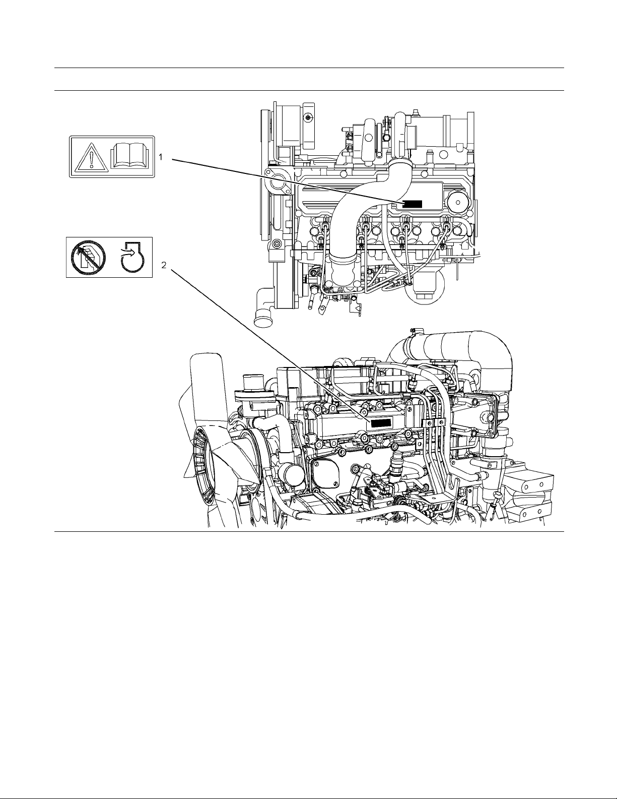
Illustration 1
Typical example
(1) Universal Warning (2) Warning label for the Starting Aid
g01353473
Page 7
SEBU8324 7
Safety Section
General Hazard Information
Universal Warning (1)
The universal warning label (1) is located on the top
of the valve mechanism cover.
g01273386
Do not operate or work on this engine unless you
have read and understand the instructions and
warnings in the Operation and Maintenance Manual. Fail ure to follow the instructions or heed the
warnings could result in injury or de ath.
i02328435
General Hazard Information
Illustration 2
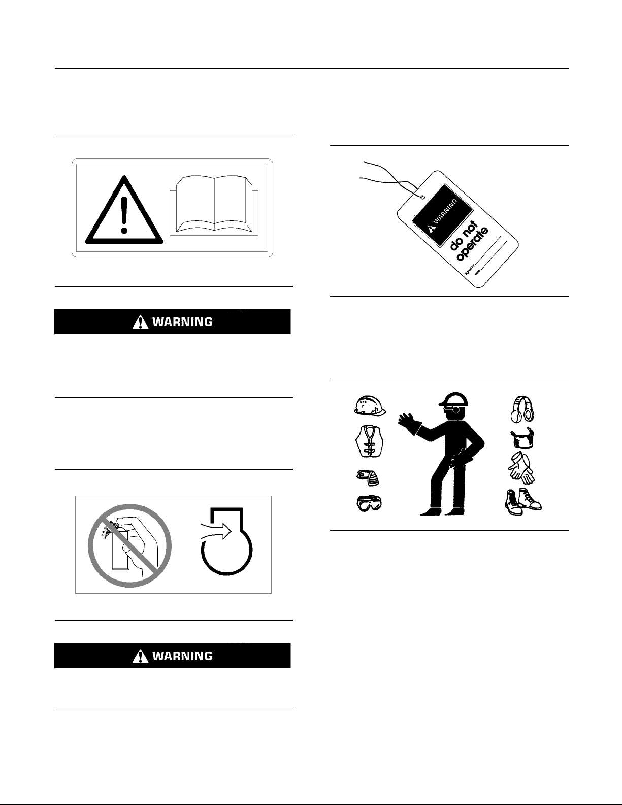
Attach a “Do Not Operate” warning tag or a similar
warning tag to the start switch or to the controls
before you s
ervice the equipment or before you
repair the equipment.
g00104545
Starting Aid (2)
The warning label for the starting aid (2) is located on
the side of the air inlet manifold.
g01273387
Do not use aerosol types of starting aids such as
ether.
personal injury.
Such use could result in an explosion and
Illustration 3
g0070202
Wear a hard hat, protective glasses, and other
protective equipment, as required.
Do not wear loose clothing or jewelry that can snag
on controls or on other parts of the engine.
Make sure that all protective guards and all covers
are secured in place on the engine.
Keep the engine free from foreign material. Remove
debris, oil, tools, and other items from the deck, from
walkway
s, and from steps.
Never put maintenance fluids into glass containers.
Drain al
l liquids into a suitable container.
0
Obey all local regulations for the disposal of liquids.
Use all cleaning solutions with care.
Page 8
8 SEBU8324
Safety Section
Burn Prevention
Report all nece
Do not allow unauthorized personnel on the
equipment.
Ensure that the power supply is disconnected before
youworkonthe
Perform maintenance on the engine with the
equipment in t
OEM information for the procedure for placing the
equipment in the servicing position.
ssary repairs.
bus bar or the glow plugs.
he servicing position. Refer to the
Pressure Air and Water
Pressurized air and/or water can cause debris
and/or hot water to be blown out. This could result in
personal inj
The direct application of pressurized air or
pressurize
injury.
When pressu
cleaning, wear protective clothing, protective shoes,
and eye protection. Eye protection includes goggles
or a protect
The maximum air pressure for cleaning purposes
must be belo
water pressure for cleaning purposes must be below
275kPa(40psi).
ury.
d water to the body could result in personal
rized air and/or water is used for
ive face shield.
w 205 kPa (30 psi). The maximum
Illustration 4
Always use a board or cardboard when you check
for a leak. Leaking fluid that is under pressure can
penetrate body tissue. Fluid penetration can cause
serious injury and possible death. A pin hole leak can
cause severe injury. If fluid is injected into your skin,
you must get treatment immediately. Seek treatment
from a doctor that is familiar with this type of injury.
g00687600
Containing Fluid Spillage
Care must be taken in order to ensure that fluids
are contained during performance of inspection,
maintenance, testing, adjusting and repair of the
engine. Make provision to collect the fluid with a
suitable container before any compartment is opened
or before any component is disassembled.
Fluid Penetration
Pressure can be trapped in the hydraulic circuit long
after the engine has been stopped. The pressure can
cause hyd
escape rapidly if the pressure is not relieved correctly.
Do not rem
until pressure has been relieved or personal injury
may occur. Do not disassemble any hydraulic
componen
or personal injury may occur. Refer to the OEM
information for any procedures that are required to
relieve
raulic fluid or items such as pipe plugs to
ove any hydraulic components or parts
ts or parts until pressure has been relieved
the hydraulic pressure.
Only use the tools that are suitable for collecting
•
fluids and equipment that is suitable for collecting
fluids.
Only use the tools that are suitable for containing
•
fluids and equipment that is suitable for containing
fluids.
Obey all local regulations for the disposal of liquids.
i01480768
Burn Pre
Do not touch any part of an operating engine.
Allow the engine to cool before any maintenance
is perfo
in the air system, in the hydraulic system, in the
lubrication system, in the fuel system, or in the
coolin
items are disconnected.
rmed on the engine. Relieve all pressure
g system before any lines, fittings or related
vention
Page 9

SEBU8324 9
Safety Section
Fire Prevention and Explosion Prevention
Coolant
When the engine is at operating temperature, the
engine coolant is hot. The coolant is also under
pressure. The radiator and all lines to the heaters or
to the engine contain hot coolant.
Any contact with hot coolant or with steam can cause
severe burns. Allow cooling system components to
cool before the cooling system is drained.
Check the coolant level after the engine has stopped
and the engine has been allowed to cool.
Ensure that th e filler cap is cool before removing the
filler cap. The fi ller cap must be cool enough to touch
withabarehand.Removethefiller cap slowly in
order to relieve pressure.
Cooling system conditioner contains alkali. Alkali can
cause personal injury. Do not allow alkali to contact
the skin, the eyes, or the mouth.
Oils
Hot oil and hot lubricating components can cause
personal injury. Do not allow hot oil to contact the
skin. Also, do not allow hot components to contact
the skin.
Batteries
Electrolyte is an acid. Electrolyte can cause personal
injury. Do not allow electrolyte to contact the skin or
the eyes. Always wear protective glasses for servicing
batteries. Wash hands after touching the batteries
and connectors. Use of gloves is recommended.
i028134
Fire Preventio n and Exp losio n
Prevent
ion
All fuels, most
are flammable.
Flammable flui
surfaces or onto electrical components can cause
a fire. Fire may cause personal injury and property
damage.
A flash fire may result if the covers for the engine
crankcase ar
an emergency shutdown.
Determine wh
environment that allows combustible gases to be
drawn into the air inlet system. These gases could
cause the eng
property damage, or engine damage could result.
If the appli
gases, consult your Perkins dealer and/or your
Perkins distributor for additional information about
suitable p
Remove all flammable combustible materials or
conductiv
the engine. Do not allow any flammable combustible
materials or conductive materials to accumulate on
the engine
Store fuels and lubricants in correctly marked
container
oily rags and any flammable materials in protective
containers. Do not smoke in areas that are used for
storing fl
Do not expose the engine to any flame.
Exhaust shields (if equipped) protect hot exhaust
components from oil or fuel spray in case of a line,
88
a tube, or
installed correctly .
Do not we
fluids. Do not flame cut lines or tanks that contain
flammable fluid. Clean any such lines or tanks
thoroug
welding or flame cutting.
hly with a nonflammable solvent prior to
lubricants, and some coolant mixtures
ds that are leaking or spilled onto hot
e removed within fifteen minutes after
ether the engine will be operated in an
ine to overspeed. Personal injury,
cation involves the presence of combustible
rotection devices.
e materials such as fuel, oil, and debris from
.
s away from unauthorized persons. Store
ammable materials.
a seal failure. Exhaust shields must be
ld on lines or tanks that contain flammable
Illust
ration 5
g00704000
Wiring m
wires must be correctly routed and securely attached.
Check all electrical wires daily. Repair any wires
that ar
engine. Clean all electrical connections and tighten
all electrical connections.
Eliminate all wiring that is unattached or unnecessary.
Do not use any wires or cables that are smaller than
the rec
and/or circuit breakers.
ust be kept in good condition. All electrical
e loose or frayed before you operate the
ommended gauge. Do not bypass any fuses
Page 10
10 SEBU8324
Safety Section
Fire Prevention and Explosion Prevention
Arcing or spark
ing could cause a fire. Secure
connections, recommended wiring, and correctly
maintained battery cables will help to prevent arcing
or sparking.
Inspect all lines and hoses for wear or for
deteriorati
on. The hoses must be correctly routed.
The lines and hoses must have adequate support
and secure clamps. Tighten all connections to the
recommended
torque. Leaks can cause fires.
Oil filters and fuel filters must be correctly installed.
The filter hou
sings must be tightened to the correct
torque.
Illustration 7
g00704135
Gases from a battery can explode. Keep any open
flames or sparks away from the top of a battery. Do
not smoke in battery charging areas.
Illustration 6
g00704059
Use caution when you are refueling an engine. Do
not smoke while you are refueling an engine. Do not
refuel an engine near open flames or sparks. Always
stop the engine before refueling.
Never check the battery charge by placing a metal
object across the terminal posts. Use a voltmeter or
ahydrometer.
Incorrect jumper cable connections can cause
an explosion that can result in injury. Refer to
the Operation Section of this manual for specific
instructions.
Do not charge a frozen battery. This may cause an
explosion.
The batteries must be kept clean. The covers
(if equipped) must be kept on the cells. Use the
recommended cables, connections, and battery box
covers when the engine is operated.
Fire Extinguisher
Make sure that a fire extinguisher is available. Be
familiar with the operation of the fire extinguisher.
Inspect the fire extinguisher and service the fire
extinguisher regularly. Obey the recommendations
on the instruction plate.
Lines, Tubes and Hoses
Donotbendhighpressurelines.Donotstrikehigh
pressure lines. Do not install any lines that are bent
or damaged. Do not clip any other items to the high
pressure lines.
Page 11

SEBU8324 11
Safety Section
Crushing Prevention and Cutting Prevention
Repair any line
can cause fires. Consult your Perkins dealer or your
Perkins distributor for repair or for replacement parts.
Check lines, tubes and hoses carefully. Do not use
your bare hand to check for leaks. Use a board or
cardboard to
to the recommended torque.
Replace the p
are present:
End fittings a
•
Outer coverings are chafed or cut.
•
Wires are exposed.
•
Outer coveri
•
Flexible part of the hoses are kinked.
•
Outer covers have embedded armoring.
•
End fittings a
•
Make sure that all clamps, guards, and heat shields
are installe
will help to prevent vibration, rubbing against other
parts, and excessive heat.
s that are loose or damaged. Leaks
check for leaks. Tighten all connections
arts if any of the following conditions
re damaged or leaking.
ngs are ballooning.
re displaced.
d correctly. During engine operation, this
i02235492
Mounting and Dismounting
Inspect the ste
before mounting the engine. Keep these items clean
and keep these items in good repair.
Mount the engine and dismount the engine only at
locations that have steps and/or handholds. Do not
climb on the en
Face the engine in order to mount the engine or
dismount the
with the steps and handholds. Use two feet and one
hand or use one foot and two hands. Do not use any
controls as h
Do not stand on components which cannot support
your weight
platform. Secure the climbing equipment so that the
equipment will not move.
Do not carry tools or supplies when you mount the
engine or when you dismount the engine. Use a hand
line to rais
ps, the handholds, and the work area
gine, and do not jump off the engine.
engine. Maintain a three-point contact
andholds.
. Use an adequate ladder or use a work
e and lower tools or supplies.
i01805780
i01359666
Crushing Prevention and
Cutting Prevention
Support th
the component is performed.
Unless oth
never attempt adjustments while the engine is
running.
Stay clear of all rotating parts and of all moving
parts. Leave the guards in place until maintenance
is perfor
reinstall the guards.
Keep obje
blades will throw objects or cut objects.
When obje
order to avoid injury to the eyes.
Chips or o
are struck. Before objects are struck, ensure that no
one will be injured by flying debris.
e component properly when work beneath
er maintenance instructions are provided,
med. After the maintenance is performed,
cts away from moving fan blades. The fan
cts are struck, wear protective glasses in
ther debris may fly off objects when objects
Before Starting Engine
NOTICE
For initial start-up of a new or rebuilt engine, and for
start-up o
provision to shut the engine off should an overspeed
occur. This may be accomplished by shutting off the
air and/o
Overspeed shutdown should occur automatically.
If automa
emergency stop button in order to cut the fuel and/or
air to the engine.
Inspect the engine for potential hazards.
Before st
underneath, or close to the engine. Ensure that the
area is free of personnel.
If equipped, ensure that the lighting system for the
engine is suitable for the conditions. Ensure that all
lights w
f an engine that has been serviced, make
r fuel supply to the engine.
tic shutdown does not occur, press the
arting the engine, ensure that no one is on,
ork properly, if equipped.
Page 12
12 SEBU8324
Safety Section
Engine Starting
All protective
be installed if the engine must be started in order
to perform service procedures. To help prevent an
accident that
around the parts carefully.
Do not bypass
disable the automatic shutoff circuits. The circuits are
provided in order to help prevent personal injury. The
circuits are
engine damage.
See the Servi
adjustments.
guards and all protective covers must
is caused by parts in rotation, work
the automatic shutoff circuits. Do not
also provided in order to help prevent
ce Manual for repairs and for
i01933350
Engine Starting
Do not use aerosol types of starting aids such as
ether. Such use could result in an explosion and
personal injury.
If a warning tag is attached to the engine start switch
or to the controls, DO NOT start the engine or move
the controls. Consult with the person that attached
the warning tag before the engine is started.
All protective guards and all protective covers must
be installed if the engine must be started in order
to perform service procedures. To help prevent an
accident that is caused by parts in rotation, work
around the parts carefully.
Start the engine from the operator’s compartment or
from the engine start switch.
Note: The engin
device for cold starting for normal conditions of
operation. If the engine will be operated in very cold
conditions, t
required. Normally, the engine will be equipped with
the correct type of starting aid for your region of
operation.
The 800 Series engine is equipped with a glow plug
starting aid
intake air in order to improve starting.
e is equipped with an automatic
henanextracoldstartingaidmaybe
in each individual cylinder that heats the
i01032808
Engine Stopping
To avoid overheating of the engine and accelerated
wear of the engine components, stop the engine
according to this Operation and Maintenance Manual,
“Engine Stopping” topic (Operation Section).
Use the Emergency Stop Button (if equipped)
ONLY in an emergency situation. DO NOT use the
Emergency Stop Button for normal engine stopping.
After an emergency stop, DO NOT start the engine
until the problem that caused the emergency stop
has been corrected.
On the initial start-up of a new engine or an engine
that has been serviced, make provisions to stop the
engine if an overspeed condition occurs. This may be
accomplished by shutting off the fuel supply and/or
the air supply to the engine.
i021766
Electrical System
68
Always start the engine according to the procedure
that is described in the Operation and Maintenance
Manual, “Engine Starting” topic in the Operation
Section. Knowing the correct procedure will help to
prevent major damage to the engine components.
Knowing the procedure will also help to prevent
personal injury.
To ensure that the jacket water heater (if equipped)
and/or the lube oil heater (if equipped) is working
properly, check the water temperature gauge and the
oil temperature gauge during the heater operation.
Engine exhaust contains products of combustion
which can be harmful to your health. Always start the
engine and operate the engine in a well ventilated
area. If the engine is started in an enclosed area,
vent the engine exhaust to the outside.
Never di
circuit cable from the battery when the charging unit
is operating. A spark can cause the combustible
gases th
To help prevent sparks from igniting combustible
gases t
negative “−” jump start cable should be connected
last from the external power source to the negative
“−”ter
is not equipped with a negative “−” terminal, connect
the jump start cable to the engine block.
Check the electrical wires daily for wires that are
loose or frayed. Tighten all loose electrical wires
befor
electrical wires before the engine is started. See
the Operation and Maintenance Manual for specific
start
sconnect any charging unit circuit or battery
at are produced by some batteries to ignite.
hat are produced by some batteries, the
minal of the starting motor. If the starting motor
e the engine is started. Repair all frayed
ing instructions.
Page 13

SEBU8324 13
Safety Section
Electrical System
Grounding Practices
Correct grounding for the engine electrical system
is necessary for optimum engine performance
and reliability. Incorrect grounding will result in
uncontrolled electrical circuit paths and in unreliable
electrical circuit paths.
Uncontrolled electrical circuit paths can result in
damage to main bearings, to crankshaft bearing
journal surfaces, and to aluminum components.
Engines that are installed without engine-to-frame
ground straps can be damaged by electrical
discharge.
To ensure that the engine and the engine electrical
systems function correctly, an engine-to-frame
ground strap with a direct path to the battery must be
used. This path may be provided by way of a direct
engine ground to the frame.
All grounds should be tight and free of corrosion. The
engine alternator must be grounded to the negative
“-” battery terminal with a wire that is adequate to
handle the full charging current of the alternator.
Page 14
14 SEBU8324
Product Information Section
Model Views
Product Information
Section
Model Views
i02697676
Model View Illustrations
Illustration 8
Left side view of a naturally aspirated engine
This view is shown without one of the fuel injectors for clarity.
(1) Fan
(2) Fuel injector
(3) Glow plug
(4) Oil filler cap
(5) L ifting eye
(6) Water drain plug or drain valve
(7) Oil level gauge
(8) Flywheel housing
(9) Oil filter
(10) R elief valve
g01264543
(11) Oil drain plug
(12) Oil pressure switch
(13) Fuel injection pump
(14) Oil F iller
(15) Water pump
Page 15
SEBU8324 15
Product Information Section
Model Views
Illustration 9
(16) O il filler cap
(17) Lifting eye
(18) T hermostat
(19) Alte rnator
(20) V-Belt
(21) Crankshaft vibration damper
g01264517
(22) Starting motor
(23) Exhaust manifold
Page 16
16 SEBU8324
Product Information Section
Model Views
Illustration 10
Left s ide view of turbocharged engine
(1) Glow plug
(2) Inlet manifold
(3) Fuel injector
(4) C rankcase breather
(5) Water dr ain plug or drain valve
(6) Oil level gauge
(7) Fuel injection pump
(8) Oil filter
(9) Relief valve
(10) Oil drain plug
g01353575
(11) Oil filler
(12) V -belt
(13) O il cooler
(14) F an
Page 17
SEBU8324 17
Product Information Section
Model Views
Illustration 11
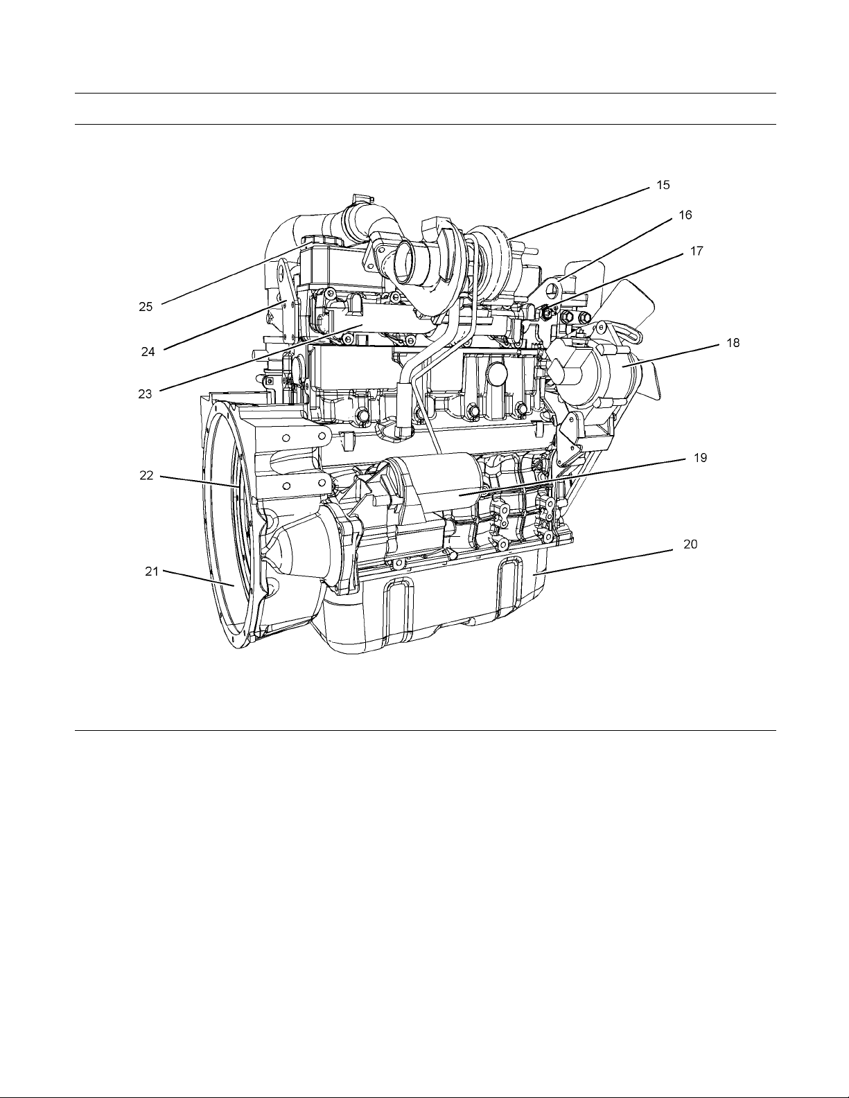
Right side view of turbocharged engine
(15) Turbocharger
(16) F ront lifting eye
(17) Coolant switch
(18) A lternator
(19) Starting motor
(20) O il pan
(21) Flywheel housing
(22) Flywheel
g01353864
(23) Exhaust manifold
(24) Re a r lifting eye
(25) Top oil filler
Page 18

18 SEBU8324
Product Information Section
Model Views
i02700110
Engine Description
Table 1
Naturally Aspirated Specifications
Type
Number of Cylinders
Bore
Stroke 120 mm (4.72 inch)
Aspiration Naturally Aspirated
Compression ratio 22:1
Displacement 3.33 L (203 in3)
Firing Order
Rotation that is viewed
from the flywheel
Valve Lash Setting (Inlet) 0.25 mm (0.0098 inch)
Valve Lash Setting
(Exhaust)
Table 2
Turbocharged Specifications
Type
Number of Cylinders 4 In-Line
Bore 94 mm (3.70 inch)
Stroke 120 mm (4.72 inch)
Aspiration Turbocharged
Compressio
(73.7 hp)
Compression ratio 62 kW
(83 hp)
Displacement 3.33 L (203 in3)
Firing Order 1-3-4-2
Rotation that is viewed
from the flywheel
Valve Lash Setting (Inlet) 0.25 mm (0.0098 inch)
Valve Lash Setting
(Exhaust)
nratio55kW
Four Stroke Cycle
4 In-Line
94 mm (3.70 inch)
1-3-4-2
Counterclockwise
0.25 mm (0.0098 inch)
Four Stroke Cycle
20.5:1
19.5:1
Counterclockwise
0.25 mm (0.0098 inch)
Water temperat
•
ure regulators which regulate the
engine coolant temperature
Gear-driven o
•
Oil cooler
•
il pump (gear type)
The engine lubricating oil is supplied by a gear
type pump. The engine lubricating oil is cooled and
the engine lub
ricating oil is filtered. Bypass valves
provide unrestricted flow of lubrication oil to the
engine parts when oil viscosity is high. Bypass valves
canalsoprov
ide unrestricted flow of lubrication oil
to the engine parts if the oil cooler should become
plugged or if the oil filter element should become
plugged.
Engine efficiency, efficiency of emission controls, and
engine perf
ormance depend on adherence to proper
operation and maintenance recommendations.
Engine performance and efficiency also depend on
the use of r
ecommended fuels, lubrication oils, and
coolants. Refer to the Operation and Maintenance
Manual, “Maintenance Interval Schedule” for more
informati
Engine Ser
on on maintenance items.
vice Life
Engine efficiency and maximum utilization of engine
performan
ce depend on the adherence to proper
operation and maintenance recommendations. In
addition, use recommended fuels, coolants and
lubrican
ts. Use the Operation and Maintenance
Manual as a guide for required engine maintenance.
Expected
engine life is generally predicted by the
average power that is demanded. The average power
that is demanded is based on fuel consumption of
the engi
ne over a period of time. Reduced hours of
operation at full throttle and/or operating at reduced
throttle settings result in a lower average power
demand.
Reduced hours of operation will increase
the length of operating time before an engine
overhaul is required.
Engine Cooling and Lubrication
The cooling system consists of the following
components:
Gear-driven centrifugal water pump
•
Page 19
SEBU8324 19
Product Information Section
Product Identification Information
Product Identification
Information
Plate Locations and Film
Locations
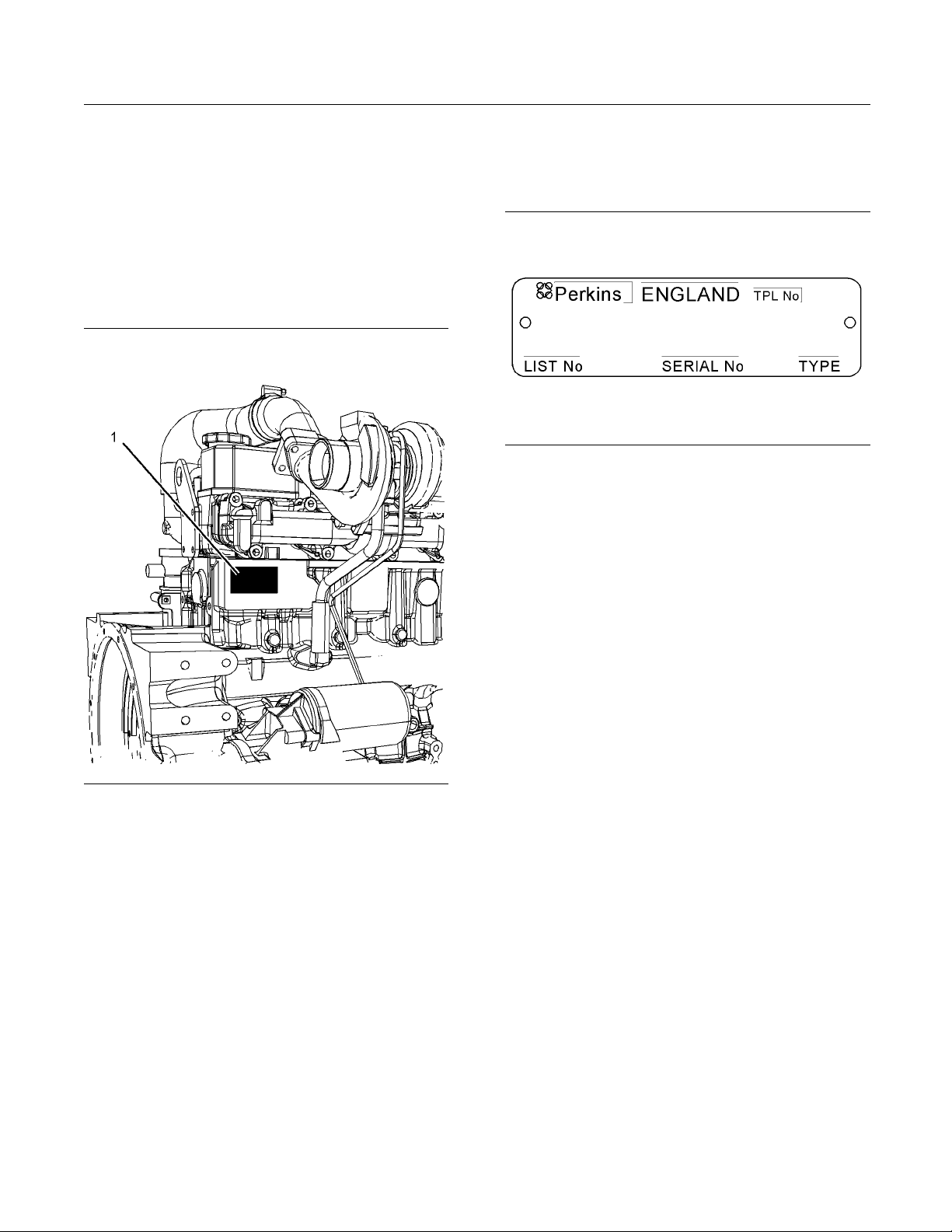
i02741945
Serial Number Plate (1)
The engine serial number plate is located on the right
side of the cylinder block at the rear of the engine.
Illustration 13
Serial number plate
g01094203
i02164876
Reference Numbers
Illustration 12
Location of serial number plate
Perkins engines are identified by an engine serial
number.
An example of an engine number is UL*****J000001L.
UL
__________________________________________Type of engine
____________________ The list number for the engine
*****
______________________________________________ Built in Japan
J
g01372283
Information for the following items may be needed to
order parts
Record the information in the appropriate space.
Make a copy of this list for a record. Keep the
informatio
Record for
Engine Model _ ______________________________________________
Engine Serial number _____________________________________
Engine Low
Engine Full Load rpm ________ _____________________________
Primary Fuel Filter _________________________________________
Water Sepa
Secondary Fuel Filter Element ____________________ ______
Lubrication Oil Filter Element ___________________________
. Locate the information for your engine.
n for future reference.
Reference
Idle rpm
rator Element
______________________________________
________________________________
000001
L
Perkins distributors need all of these numbers
in order to determine the components that were
included with the engine. This permits accurate
identification of replacement part numbers.
___________________________ Engine Serial Number
_____________________________________ Year of Manufacture
Auxiliary
Total Lubrication System Capacity _____________ ________
Total Cooling System Capacity _________________________
Air Cleane
Oil Filter Element
r Element
_______________________________
_______________________________________
Page 20
20 SEBU8324
Product Information Section
Product Identification Information
Fan Drive Belt _
_____________________________________________
Alternator Belt ______________________________________________
i02742745
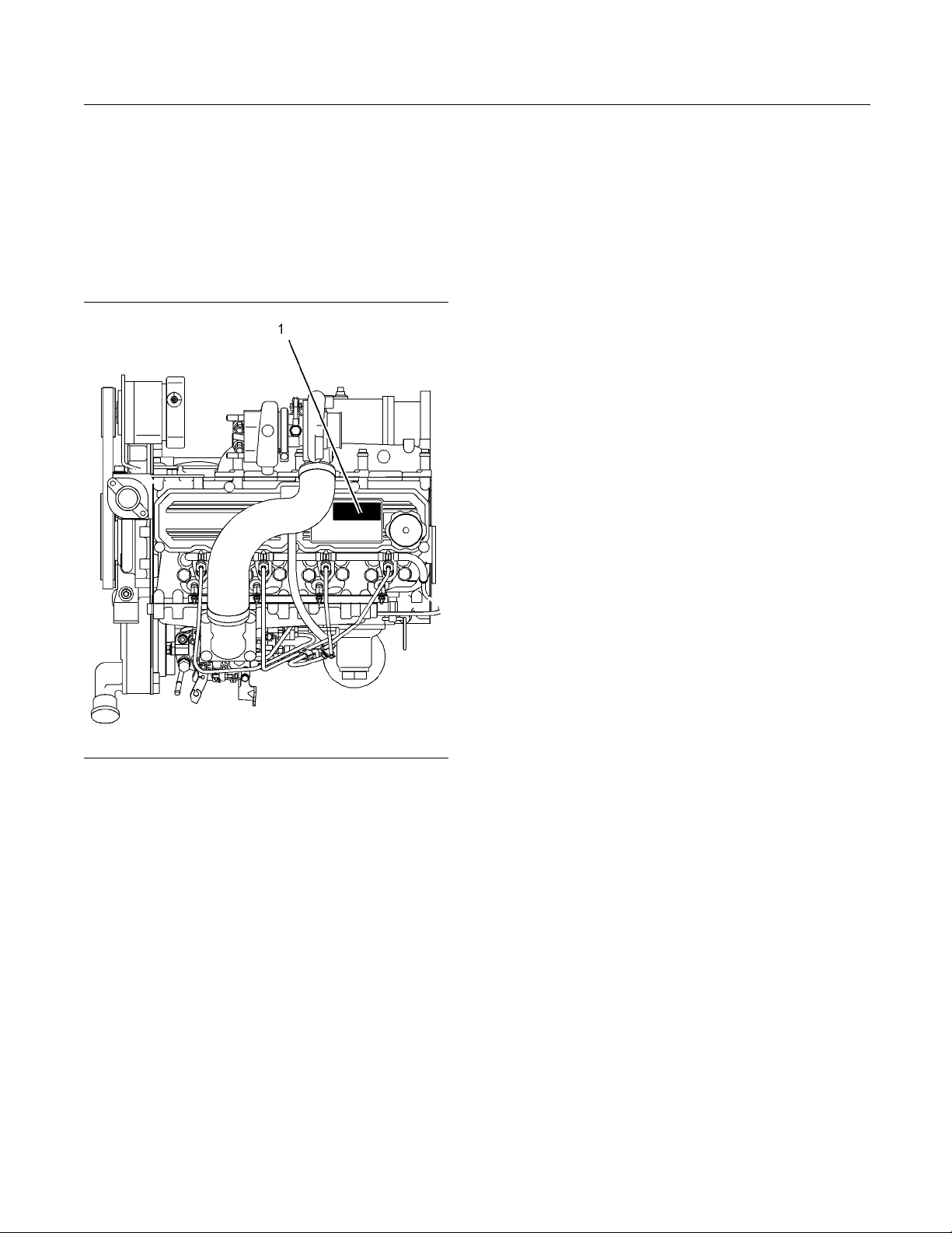
Emissions Certification Film
Illustration 14
Typical exa mple
EPA Environmental Protection Agency
•
CARB California Air Resources Board
•
EEC European Economic Community
•
g01372645
The emissions label (1) is located on the top of the
valve mechanism cover. The 800D industrial engine
complies with worldwide emissions standards and
with EPA/CARB off road Tier iii engines. The 800D
industrial engine complies with EEC off road mobile
machinery that is at stage III.
Page 21
SEBU8324 21
Product Information Section
Product Identification Information
Illustration 15
Typical ex
ample
g01381011
Page 22
22 SEBU8324
Operation Section
Lifting and Storage
Operation Section
Lifting and Storage
i02513632
Product Lifting
Illustration 16
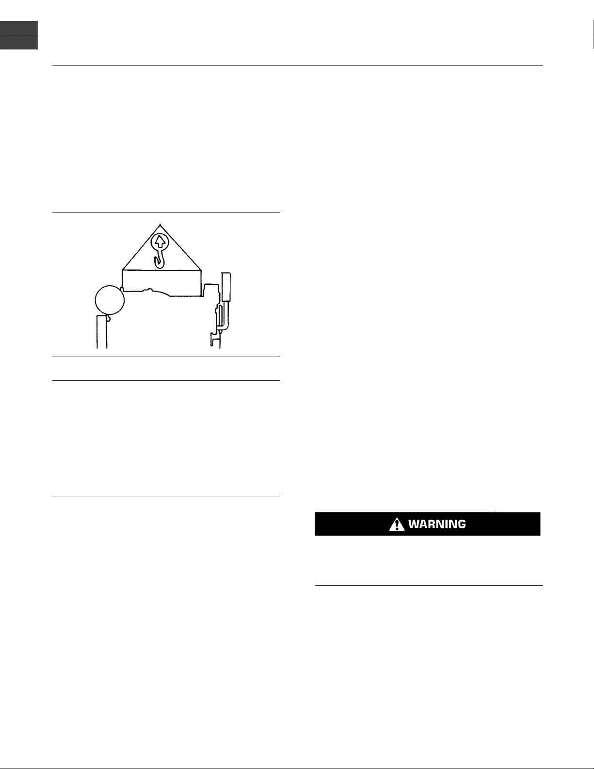
NOTICE
Never bend the eyebolts and the brackets. Only load
the eyebolts and the brackets under tension. Remember that the capacity of an eyebolt is less as the angle
between the supporting members and the object becomes less than 90 degrees.
g00103219
i02744521
Product Storage
If the engine is
lubricating oil will drain from the cylinder walls and
from the piston rings. Rust can form on the cylinder
walls. Rust on
engine wear and a reduction in engine service life.
Perkins are no
occur when an engine is in storage after a period in
service.
Your Perkins distributor can assist in preparing the
engine for extended storage periods.
If an engine is out of operation and if use of the
engine is not planned for more than one month, a
complete pr
To help prevent excessive engine wear and corrosion
to the engin
1. Completely clean the outside of the engine.
2. Ensure that the vehicle is on level ground.
3. Drain the fu
thesystemwithpreservativefuel.1772204
POWERPARTLay-Up1canbemixedwith
the normal f
preservative fuel.
not started for a month or longer the
the cylinder walls will cause increased
t responsible for damage which may
otection procedure is recommended.
e, use the following guidelines:
el system completely and refill
uel in order to change the fuel into
When it is necessary to remove a component at an
angle, only use a link bracket that is properly rated for
the weight.
Use a hoist to remove heavy components. Use
an adjustable lifting beam to lift the engine. All
supporting members (chains and cables) should be
parallel to each other . The chains and cables should
be perpendicular to the top of the object that is being
lifted.
Some removals require lifting the fixtures in order to
obtain proper balance and safety.
ToremovetheengineONLY,usetheliftingeyesthat
are on the engine.
Lifting eyes are designed and installed for specific
engine arrangements. Alterations to the lifting eyes
and/or the engine make the lifting eyes and the lifting
fixtures obsolete. If alterations are made, ensure
that proper lifting devices are provided. Consult your
Perkins dealer for information regarding fixtures for
proper engine lifting.
If preserv
can be filled with normal fuel. This fuel must be
discarded at the end of the storage period together
with the fu
Personal
contact with hot coolant or with steam can cause
severe burns. Allow cooling system components
to cool be
4. Drain and refill the cooling system. Refer to this
Operatio
System coolant (Commercial Heavy Duty Change or Cooling System coolant (ELC) Change”
refilling the cooling system.
5. Operate
normal operating temperature. If necessary,
perform minor adjustments. Check for any leaks.
Stop the
system and from the cooling, lubrication or air
systems.
ative fuel is not available, the fuel system
el filter elements.
injury can result from hot coolant. Any
fore the cooling system is drained.
n and Maintenance Manual, “Cooling
for information on draining, flushing and
the engine until the engine reaches
engine. Repair any leaks from the fuel
Page 23

SEBU8324 23
Operation Section
Lifting and Storage
6. Drain the lubri
Renew the canister(s) of the lubricating oil filter.
Fill the oil pan to the Full Mark on the engine oil
level gauge with new, clean lubricating oil. Add
1762811 POWER
order to protect the engine against corrosion. If
1762811 POWERPART Lay-Up 2 is not available,
use a preserv
instead of the lubricating oil. If a preservative is
used, t his must be drained completely at the end
of the storag
refilled to the correct level with normal lubricating
oil.
7. Operate the engine in order to circulate engine oil.
8. Disconnect
in a fully charged condition. Protect the terminals
against corrosion. 1734115 POWERP ART
Lay-Up3ca
battery into safe storage.
9. If equippe
element. Seal the end of the breather pipe.
cating oil from the oil pan.
PART Lay-Up 2 to the oil in
ative of the correct specification
e period and the oil pan must be
the battery. Ensure that the battery is
nbeusedontheterminals.Putthe
d, replace the crankcase breather
17. In order to prev
of the engine, spray the engine with 1734115
POWERPART Lay-Up 3. Do not spray the area
inside the alt
ent corrosion to the outside
ernator.
10. Remove the
1762811 POWERPARTLay-Up2aroundthe
rocker shaft assembly.
11. Remove the glow plugs. Slowly rotate the
crankshaft. By checking the valves, position the
piston at B
Lay-Up 2 for two seconds into the cylinder bore.
This procedure must be carried out on each
cylinder
12. Install the glow plugs. Install the valve mechanism
cover.
13. Remove the pipes that are installed between
the air fi
Spray 1762811 POWERPART Lay-Up 2 into
the turbocharger. The duration of the spray is
printed
with waterproof tape .
14. Remove t
the turbocharger. Spray 1762811 POWERPART
Lay-Up 2 into the turbocharger. The duration of
the spr
turbocharger with waterproof tape.
valve mechanism cover. Spray
DC. Spray 1762811 POWERPART
.
lter assembly and the turbocharger.
on the container. Seal the turbocharger
he exhaust pipe from the output side of
ay is printed on the container. Seal the
15. Seal th
with waterproof tape .
16. Remove
belt into storage.
e vent of the fuel tank or the fuel filler cap
the alternator drive belt and put the drive
Page 24

24 SEBU8324
Operation Section
Gauges and Indicators
Gauges and Ind icators
i02164190
Gauges and Indicators
Your engine m
the gauges that are described. For more information
about the gauge package, see the OEM information.
Gauges provide indications of engine performance.
Ensure that the gauges are in good working order.
Determine th
the gauges over a period of time.
Noticeable c
potential gauge or engine problems. Problems may
also be indicated by gauge readings that change
even if the r
Determine and correct the cause of any significant
change in the readings. Consult your Perkins dealer
or your Per
If no oil pressure is indicated, STOP the engine. If
maximum co
the engine. Engine damage can result.
SAE10W30
rpm.
ay not have the same gauges or all of
e normal operating range by observing
hanges in gauge readings indicate
eadings are within specifications.
kins distributor for assistance.
NOTICE
olant temperature is exceeded, STOP
Engine Oil
should be greatest after a cold engine is
started. The typical engine oil pressure with
is 207 to 413 kPa (30 to 60 psi) at rated
Pressure – The oil pressure
1. Reduce the load
2. Inspect the cooling system for leaks.
3. Determine if the engine must be shut down
immediately or if the engine can be cooled by
reducing the l
Tachometer – This gauge indicates engine
speed (rpm). W
ismovedtothefullthrottlepositionwithout
load, the engine is running at high idle. The engine is
running at th
lever is at the full throttle position with maximum
rated load.
To help prevent engine damage, never exceed the
high idle rpm. Overspeeding can result in serious
damage to the engine. The engine can be operated
at high idle without damage, but should never be
allowedtoexceedhighidlerpm.
indicator should be to the right side of “0” (zero).
is in the “ON” position.
efullloadrpmwhenthethrottlecontrol
Ammeter – This gauge indicates the
amount of charge or discharge in the
battery charging circuit. Operation of the
Fuel Level – This gauge indicates the fuel
level in the fuel tank. The fuel level gauge
operates when the “START/STOP” switch
Service Hour Meter – The gauge indicates
operating time of the engine.
and the engine rpm.
oad.
hen the throttle control lever
NOTICE
A lower oil pressure is normal at low idle. If the load
is stable
the following procedure:
1. Remove th
2. Reduce engine speed to low idle.
3. Check and maintain the oil level.
tempera
48 kPa (7 psi) is 110°C (230°F). Higher temperatures
may occur under certain conditions. The water
tempera
reading should never exceed the boiling point for the
pressurized system that is being used.
If the en
and steam becomes apparent, perform the following
procedure:
and the gauge reading changes, perform
e load.
Jacket Wa
Typical temperature range is 71 to 96°C
(160 to 205°F). The maximum allowable
ture with the pressurized cooling system at
ture reading may vary according to load. The
gine is operating above the normal range
ter Coolant Temperature –
Page 25

SEBU8324 25
Operation Section
Features and Controls
Features and Controls
i02672017
Engine Shutoffs and Engine
Alarms
Shutoffs
Shutoffs and alarms are electrically operated or
mechanically operated. The operation of all electric
shutoffs and alarms utilize components which actuate
switches in a sensing unit.
Shutoffs are set at critical levels for the following
items: operating temperature, operating pressure,
operating level, and operating rpm. The particular
shutoff may need to be reset before the engine will
start.
NOTICE
Always determine the cause of the engine shutdown.
Make necessary repairs before attempting to restart
the engine.
Be familiar with the following items:
Engines may be e
to alert the operator when undesirable operating
conditions occur.
When an alarm is
be taken before the situation becomes an emergency
in order to avoid possible engine damage.
If corrective measures are not taken within a
reasonable time, engine damage could result. The
alarm will co
The alarm may need to be reset.
Aswitchmayb
engine is stopped for repairs. Before the engine is
started, ensure that the switch is moved to the ON
position and
engine will not be protected if the switch is left in the
OFF position.
quipped with alarms in order
NOTICE
activated, corrective measures must
ntinue until the condition is corrected.
e installed in the alarm while the
that the warning lights are flashing. The
Testing the Shutoff and Alarm
System
Most contro
switch.TurntheswitchtotheONpositioninorder
to check the indicator lights for proper operation.
Replace fa
l panels are equipped with a lamp test
ulty bulbs immediately.
Types and locations of shutoff
•
Conditions which cause each shutoff to function
•
The resetting procedure that is required to restart
•
the engine
Alarms
Alarms consist of a switch and a contactor. The
switches are wired to the contactors. The contactors
activate alarm circuits in an annunciator panel. Your
engine may be equipped with the following switches:
Engine oil pressure – The engine oil pressure
switch indicates when oil pressure drops below rated
system pressure.
Coolant level – The low coolant level switch
indicates when the coolant level is low.
Coolant temperature – The coolant temperature
switch indicates high jacket water coolant
temperature.
Note: The sensing element of the coolant
temperature switch must be submerged in coolant
in order to operate.
NOTICE
During testing, abnormal operating conditions must be
simulated
prevent possible engine damage.
Refer to th
testing procedures or consult your Perkins dealer.
. Perform the tests correctly in order to help
e Service Manual for more information on
i02539718
Fuel Shutoff
The fuel shutoff solenoid is located on the fuel
injection pump.
When the fuel shutoff solenoid is activated, the
solenoid moves to the “Open” position.
When the fuel shutoff solenoid is deactivated, the
solenoid moves to the “Closed” position.
Page 26

26 SEBU8324
Operation Section
Engine Starting
Engine Starting
i02194223
Before Starting Engine
Before the en
daily maintenance and any other periodic
maintenance that is due. Refer to the Operation
and Maintena
Schedule” for more information.
For the maxim
•
thorough inspection within the engine compartment
before the engine is started. Look for the following
items: oil l
excessive dirt and/or grease. Remove any excess
dirt and/or grease buildup. Repair any faults that
were ident
Inspect the cooling system hoses for cracks and
•
for loose c
Inspect the alternator and accessory drive belts for
•
cracks, br
Inspect the wiring for loose connections and for
•
worn wires
Check the fuel supply. Drain water from the water
•
separator
(if equipped).
All valve
and during engine operation to help prevent high fuel
pressure. High fuel pressure may cause filter housing
failure o
gine is started, perform the required
nce Manual, “Maintenance Interval
um service life of the engine, make a
eaks, coolant leaks, loose bolts, and
ified during the inspection.
lamps.
eaks, and other damage.
or frayed wires.
(if equipped). Open the fuel supply valve
NOTICE
s in the fuel return line must be open before
r other damage.
Do not start the
•
if there is a “DO NOT OPERATE” warning tag or
similar warning tag attached to the start switch or
to the control
Ensure that the areas around the rotating parts are
•
clear.
All of the guards must be put in place. Check for
•
damaged guar
any damaged guards. Replace damaged guards
and/or missing guards.
Disconnect any battery chargers that are not
•
protected against the high current drain that
is created wh
engaged. Check electrical cables and check the
battery for poor connections and for corrosion.
Reset all of the shutoffs or alarm components (if
•
equipped).
Check the engine lubrication oil level. Maintain the
•
oil level between the “ADD” mark and the “FULL”
mark on the
Check the coolant level. Observe the coolant level
•
in the head
coolant level to the “FULL” mark on the header
tank.
If the engine is not equipped with a header tank
•
maintain the coolant level within 13 mm (0.5 inch)
of the bott
equipped with a sight glass, maintain the coolant
level in the sight glass.
Observe the air cleaner service indicator (if
•
equipped). Service the air cleaner when the yellow
diaphrag
piston locks in the visible position.
m enters the red zone, or when the red
engine or move any of the controls
s.
ds or for missing guards. Repair
en the electric starting motor is
engine oil level gauge.
er tank (if equipped). Maintain the
om of the filler pipe. If the engine is
If the engine has not been started for several weeks,
fuel may h
may have entered the filter housing. Also, when fuel
filters have been changed, some air pockets will be
trapped
fuel system. Refer to the Operation and Maintenance
Manual, “Fuel System - Prime” for more information
on primi
Engine exhaust contains products of combustion
which may be harmful to your health. Always start
and ope
and, if in an enclosed area, vent the exhaust to the
outside.
ave drained from the fuel system. Air
in the engine. In these instances, prime the
ng the fuel system.
rate the engine in a well ventilated area
Ensure t
•
engine has been disengaged from the engine.
Minimize electrical loads or remove any electrical
loads.
hat any equipment that is driven by the
Page 27

SEBU8324 27
Operation Section
Engine Starting
i01934161
Starting the Engine
Do not use aerosol types of starting aids such as
ether. Such use could result in an explosion and
personal injury.
NOTICE
Do not crank the engine for more than 10 seconds.
Allow the starter motor to cool for 30 seconds before
cranking agai
flywheel is turning.
Refer to the “O
1. Remove any load from the engine. Disengage any
driven equip
2. Crank the engine. Start the engine.
n. Do not engage the starter when the
EM Manual” for your type of controls.
ment.
i02177935
Starting with Jump Start
Cables
Improper jump start cable connections can cause
an explosion resulting in personal injury.
Prevent sparks near the batteries. Sparks could
cause vapors to explode. Do not allow jump start
cable ends to contact each other or the e ngine.
Note: If it is possible, first diagnose the reason
for the starting failure. Make any necessary
repairs. If the engine will not start only due to
the condition of the battery, either charge the
battery, or start the engine with jump start cables.
The condition of the battery can be rechecked
after the engine has been switched OFF.
3. If the engine does not start, release the engine
start switch and allow the electric starting motor
to cool.
4. If the ambient temperature is low, activate the
glow plugs ac
Table 3
Temperature Preheat Time
5°C(41°F)
−5 °C (23 °F) to 4 °C (40 °F)
Less than −5°C(23°F)
Continuous Preheat
cordingtoTable3.
Preheat Times
10 seconds
20 seconds
30 seconds
60 seconds maximum
5. Crank the engine. Start the engine.
6. Allow the engine to idle for 5 to 10 minutes before
applying a load to the engine. Check the oil
pressure ga
uge. The oil pressure gauge should
be at the proper value.
NOTICE
Using a battery source with the same voltage as the
electric st
arting motor. Use ONLY equal voltage for
jump starting. The use of higher voltage will damage
the electrical system.
Do not reverse the battery cables. The alternator can
be damaged. Attach ground cable last and remove
first.
When using an external electrical source to start the
engine, tu
rn the generator set control switch to the
“OFF” position. Turn all electrical accessories OFF before attaching the jump start cables.
Ensure that the main power switch is in the OFF position before attaching the jump start cables to the engine bein
gstarted.
1. Turn the start switch to the OFF position. Turn off
all the en
gine’s accessories.
2. Connect one positive end of the jump start cable
to the pos
itive cable terminal of the discharged
battery. Connect the other positive end of the jump
start cable to the positive cable terminal of the
cal source.
electri
Page 28

28 SEBU8324
Operation Section
Engine Starting
3. Connect one neg
to the negative cable terminal of the electrical
source. Connect the other negative end of the
jump start cab
chassis ground. This procedure helps to prevent
potential sparks from igniting the combustible
gases t hat ar
4. Start the engine.
5. Immediately after the stalled engine is started,
disconnect the jump start cables in reverse order.
After jump starting, the alternator may not be able to
fully recharge batteries that are severely discharged.
The batterie
correct voltage with a battery charger after the engine
is stopped. Many batteries which are considered
unusable ar
and Maintenance Manual, “Battery - Replace” and
Testing and Adjusting Manual, “Battery - Test”.
s must be replaced or charged to the
e still rechargeable. Refer to Operation
ative end of the jump start cable
le to the engine block or to the
e produced by some batteries.
i02539705
After Starting Engine
Note: In temperatures from 0 to 60°C (32 to 140°F),
the warm-up time is approximately three to five
minutes. In temperatures below 0°C (32°F), additional
warm-up time may be required.
When the engine idles during warm-up, observe the
following conditions:
Check for any fluid or for any air leaks at idle rpm
•
and at one-half full rpm (no load on the engine)
before operating the engine under load. This is not
possible in some applications.
Operate the engine at low idle until all systems
•
achieve operating temperatures. Check all gauges
during the warm-up period.
Note: Gauge readings should be observed and
the data should be recorded frequently while the
engine is operating. Comparing the data over time
will help to determine normal readings for each
gauge.Comparingdataovertimewillalsohelp
detect abnormal operating developments. Significant
changes in the readings should be investigated.
Page 29

SEBU8324 29
Operation Section
Engine Operation
Engine Operation
i02176671
Engine Operation
Correct oper
in obtaining the maximum life and economy of
the engine. If the directions in the Operation and
Maintenance
minimized and engine service life can be maximized.
The engine ca
engine reaches operating temperature. The engine
will reach normal operating temperature sooner
during a low
power demand. This procedure is more effective than
idling the engine at no load. The engine should reach
operating
Gauge readings should be observed and the data
should be r
is operating. Comparing the data over time will
help to determine normal readings for each gauge.
Comparing
abnormal operating developments. Significant
changes in the readings should be investigated.
Engine Warm-up
1. Run the engine at low idle for three to five minutes,
or run the engine at low idle until the jacket water
temperature starts to rise.
More time may be necessary when the
temperature is below −18°C (0°F).
ation and maintenance are key factors
Manual are followed, costs can be
n be operated at the rated rpm after the
engine speed (rpm) and during a low
temperature in a few minutes.
ecorded frequently while the engine
data over time will also help detect
i01929404
i01646335
Engaging the Driven
Equipment
1. Operate the engine at one-half of the rated rpm,
when possible.
2. Engage the driven equipment without a load on
the equipment, when possible.
Interrupted starts put excessive stress on the drive
train. Interrupted starts also waste fuel. To get the
driven equip
smoothly with no load on the equipment. This
method should produce a start that is smooth and
easy. The eng
clutch should not slip.
3. Ensure that
when the engine is operating at one-half of
the rated rpm. Ensure that all gauges operate
properly.
4. Increase the engine rpm to the rated rpm. Always
increase th
the load is applied.
5. Apply the l
load. Check the gauges and equipment for proper
operation. After normal oil pressure is reached
and the tem
the engine may be operated at full load. Check
the gauges and equipment frequently when the
engine is
Extended operation at low idle or at reduced load
may cause
buildup in the cylinders. This carbon buildup
results in a loss of power and/or poor performance.
ment in motion, engage the clutch
ine rpm should not increase and the
the ranges of the gauges are normal
e engine rpm to the rated rpm before
oad. Begin operating the engine at low
perature gauge begins to move,
operated under load.
increased oil consumption and carbon
2. Check all of the gauges during the warm-up
period.
3. Perform a walk-around inspection. Check the
engine for fluid leaks and air leaks.
4. Increase the rpm to the rated rpm. Check for
fluidleaksandairleaks.Theenginemaybe
operated at full rated rpm and at full load when
the temperature of the water jacket reaches 60°C
(140°F).
Page 30

30 SEBU8324
Operation Section
Engine Operation
i02330149
Fuel Cons ervatio n Practices
The efficiency o
economy. Perkins design and technology in
manufacturing provides maximum fuel efficiency in
all applicati
in order to attain optimum performance for the life
of the engine.
Avoid spilling fuel.
•
Fuel expands
may overflow from the fuel tank. Inspect fuel lines for
leaks. Repair the fuel lines, as needed.
Be aware of the properties of the different fuels.
•
Use only the recommended fuels.
Avoid unnecessary idling.
•
Shut off the
time.
Observe the
•
Keep the air cleaner elements clean.
Maintain th
•
One damaged battery cell will overwork the alternator.
This will co
f the engine can affect the fuel
ons. Follow the recommended procedures
when the fuel is warmed up. The fuel
engine rather than idle for long periods of
air cleaner service indicator frequently.
e electrical systems.
nsume excess power and excess fuel.
Ensure that the drive belts are correctly adjusted.
•
The drive be
Ensure that all of the connections of the hoses are
•
tight. The
Ensure that the driven equipment is in good
•
working or
Cold engines consume excess fuel. Utilize heat
•
from the ja
system, when possible. Keep cooling system
components clean and keep cooling system
component
engine without water temperature regulators.
All of these items will help maintain operating
temperat
lts should be in good condition.
connections should not leak.
der.
cket water system and the exhaust
s in good repair. Never operate the
ures.
Page 31

SEBU8324 31
Operation Section
Engine Stopping
Engine Stopping
i02334873
Stopping the E ngine
NOTICE
Stopping the engine immediately after it has been
working under load, can result in overheating and accelerated wear of the engine components.
Avoid accelerating the engine prior to shutting it down.
Avoiding hot engine shutdowns will maximize turbocharger shaft and bearing life.
Note: Individual applications will have different
control systems. Ensure that the shutoff procedures
are understood. Use the following general guidelines
in order to stop the engine.
1. Remove the load from the engine. Reduce the
engine speed (rpm) to low idle. Allow the engine
to idle for five minutes in order to cool the engine.
2. Stop the engine after the cool down period
according to the shutoff system on the engine and
turn the ignition key switch to the OFF position.
If necessary, refer to the instructions that are
provided by the OEM.
i02176672
After Stopping Engine
Note: Before yo
the engine for at least 10 minutes in order to allow
the engine oil to return to the oil pan.
Check the crankcase oil level. Maintain the oil level
•
between the “MIN” mark and the “MAX” mark on
the engine oil
If necessary, perform minor adjustments. Repair
•
any leaks and
If the engine is equipped with a service hour meter,
•
note the read
is in the Operation and Maintenance Manual,
“Maintenance Interval Schedule”.
Fill the fuel tank in order to help prevent
•
accumulation of moisture in the fuel. Do not overfill
the fuel tan
Only use antifreeze/coolant mixtures recommended in
the Coolant Specifications that are in the Operation
and Mainten
engine damage.
Allow the en
•
u check the engine oil, do not operate
level gauge.
tighten any loose bolts.
ing. Perform the maintenance that
k.
NOTICE
ance Manual. Failure to do so can cause
gine to cool. Check the coolant level.
i01903586
Emergency
Emergency shutoff controls are for EMERGENCY use
ONLY. DO NOT use emergency shutoff devices or
controls for normal stopping procedure.
The OEM may have equipped the application with
an emergency stop button. For more information
about the emergency stop button, refer to the OEM
information.
Ensure that any components for the external system
that support the engine operation are secured after
the engine is stopped.
Stopping
NOTICE
If freezing temperatures are expected, check
•
the coolan
cooling system must be protected against freezing
to the lowest expected outside temperature. Add
the correc
Perform all required periodic maintenance on all
•
driven equ
the instructions from the OEM.
t for correct antifreeze protection. The
t coolant/water mixture, if necessary.
ipment. This maintenance is outlined in
Page 32

32 SEBU8324
Operation Section
Cold Weather Operation
Cold Weather Operation
i02717265
Cold Weather Operation
Perkins Diesel Engines can operate effectively in
cold weathe r. During cold weather, the starting and
the operation of the diesel engine is dependent on
the following items:
The type of fuel that is used
•
The viscosity of the engine oil
•
The operation of the glow plugs
•
Optional Cold starting aid
•
Battery condition
•
This section will cover the following information:
Potential problems that are caused by cold weather
•
operation
Suggest steps which can be taken in order to
•
minimize starting problems and operating problems
when the ambient air temperature is between
0° to−40 °C (32° to 40 °F).
Install the cor
•
before the beginning of cold weather.
Check all rubb
•
weekly.
Check all elec
•
fraying or damaged insulation.
Keep all batte
•
Fill the fuel tank at the end of each shift.
•
Check the air cleaners and the air intake daily.
•
Check the air intake more often when you operate
in snow.
Ensure that the glow plugs are in working order.
•
Refer to Test
-Test”.
Personal injury or property damage can result
from alcohol or starting fluids.
Alcohol or starting fluids are highly flammable and
toxic and if improperly stored could result in injury
or property
rect specification of engine lubricant
er parts (hoses, fan drive belts, etc)
trical wiring and connections for any
ries fully charged and warm.
ing and Adjusting Manual, “Glow Plug
damage.
The operation and maintenance of an engine in
freezing temperatures is complex . This is because
of the following conditions:
Weather conditions
•
Engine applications
•
Recommendations from your Perkins dealer or
your Perkins distributor are based on past proven
practices. The information that is contained in
this section provides guidelines for cold weather
operation.
Hints for Cold Weather Operation
If the engine will start, operate the engine until a
•
minimum operating temperature of 81 °C (177.8 °F)
is achieved. Achieving operating temperature will
help prevent the intake valves and exhaust valves
from sticking.
The cooling system and the lubrication system
•
for the engine do not lose heat immediately upon
shutdown. This means that an engine can be shut
downforaperiodoftimeandtheenginecanstill
have the ability to start readily.
Do not use aerosol types of starting aids such as
ether. Such use could result in an explosion and
personal injury.
Forjumpstartingwithcablesincoldweather,
•
refer to the Operation and Maintenance Manual,
“Starting with Jump Start Cables.” for instructions.
Viscosity of the Engine Lubrication
Oil
Correct engine oil viscosity is essential. Oil viscosity
affects the amount of torque that is needed to
crank the engine. Refer to this Operation and
Maintenance Manual, “Fluid Recommendations” for
the recommended viscosity of oil.
Recommendations for the Coolant
Provide cooling system protection for the lowest
expected outside temperature. Refer to this Operation
and Maintenance Manual, “Fluid Recommendations”
for the recommended coolant mixture.
Page 33

SEBU8324 33
Operation Section
Cold Weather Operation
In cold weather
correct glycol concentration in order to ensure
adequate freeze protection.
, check the coolant often for the
Engine Block Heaters
Engine block h
engine jacket water that surrounds the combustion
chambers. This provides the following functions:
Startability is improved.
•
Warm up time i
•
An electric block heater can be activated once
the engine is
is typically a 1250/1500 W unit. Consult your
Perkins dealer or your Perkins distributor for more
information
Idling the E
When idling after the engine is started in cold
weather, in
rpm. This will warm up the engine more quickly.
Maintaining an elevated low idle speed for extended
periods wil
throttle. The engine should not be “raced” in order to
speed up the warm up process.
While the engine is idling, the application of a light
load (parasitic load) will assist in achieving the
minimum op
operating temperature is 82 °C (179.6 °F).
eaters (if equipped) heat the
s reduced.
stopped. An effective block heater
.
ngine
crease the engine rpm from 1000 to 1200
l be easier with the installation of a hand
erating temperature. The minimum
Recommendations for Coolant
Warm Up
Warm up an engine that has cooled below normal
operatin
be performed before the engine is returned to full
operation. During operation in very cold temperature
conditio
result from engine operation for short intervals. This
can happen if the engine is started and the engine is
stopped
to warm up completely.
When the
temperatures, fuel and oil are not completely burned
in the combustion chamber. This fuel and oil causes
soft ca
Generally, the deposits do not cause problems and
the deposits are burned off during operation at
normal
When the engine is started and the engine is stopped
many ti
up completely, the carbon deposits become thicker.
This can cause the following problems:
g temperatures due to inactivity. This should
ns, damage to engine valve mechanisms can
many times without being operated in order
engine is operated below normal operating
rbon deposits to form on the valve stems.
engine operating temperatures.
mes without being operated in order to warm
Free operation
•
Valves become stuck.
•
Pushrods may become bent.
•
Other damage t
•
result.
For this reaso
the engine must be operated until the coolant
temperature is 71 °C (160 °F) minimum. Carbon
deposits on t
and the free operation of the valves and the valve
components will be maintained.
In addition, the engine must be thoroughly warmed in
order to keep other engine parts in better condition
and the servi
extended. Lubrication will be improved. There will be
less acid and less sludge in the oil. This will provide
longer serv
rings, and other parts. However, limit unnecessary
idle time to ten minutes in order to reduce wear and
unnecessa
of the valves is prevented.
o valve train components can
n, when the engine is started,
he valve stems will be kept at a minimum
celifeoftheenginewillbegenerally
ice life for the engine bearings, the piston
ry fuel consumption.
The Water Temperature Regulator and
Insulated
The engine is equipped with a water temperature
regulator
correct operating temperature jacket water circulates
through the engine cylinder block and into the
engine cy
cylinder block via an internal passage that bypasses
the valve of the coolant temperature regulator. This
ensures t
cold operating conditions. The water temperature
regulator begins to open when the engine jacket
water ha
temperature. As the jacket water coolant temperature
rises above the minimum operating temperature the
water te
more coolant through the radiator to dissipate excess
heat.
The progressive opening of the water temperature
regulator operates the progressive closing of the
bypass
head. This ensures maximum coolant flow to
the radiator in order to achieve maximum heat
pation.
dissi
Note: Perkins discourages the use of all air flow
iction devices such as radiator shutters.
restr
Restriction of the air flow can result in the following:
high exhaust temperatures, power loss, excessive
fan us
Heater Lines
. When the engine coolant is below the
linder head. The coolant then returns to the
hat coolant flows around the engine under
s reached the correct minimum operating
mperature regulator opens further allowing
passage between the cylinder block and
age, and reduction in fuel economy.
Page 34

34 SEBU8324
Operation Section
Cold Weather Operation
A cab heater is b
feed from the engine and the return lines from the
cab should be insulated in order to reduce heat loss
to the outside
eneficial in very cold weather. The
air.
Insulating the Air Inlet and Engine
Compartment
When temperatures below −18 °C (−0°F)willbe
frequently e
is located in the engine compartment may be
specified. An air cleaner that is located in the engine
compartment
into the air cleaner. Also, heat that is rejected by the
engine helps to warm the intake air.
Additional heat can be retained around the engine by
insulating the engine compartment.
ncountered, an air cleaner inlet that
may also minimize the entry o f snow
i01935225
Fuel and the Effect from Cold
Weather
Note: Only use grades of fuel that are recommended
by Perkins. Refer to this Operation and Maintenance
Manual, “Fuel Recommendations”.
The following fuels can be used for the Perkins 800
Series engine.
Group 1
•
Group 2
•
Group 3
•
Special Fuels
•
Perkins prefer only Group 1 and Group 2 fuels for
use in 800 Series engines. Group 3 fuels include Low
Temperature Fuels and Aviation Kerosene Fuels.
Note: Group 3 fuels reduce the life of the engine. The
use of Group 3 fuels is not covered by the Perkins
warranty.
Special fuels include Biofuel.
Group 1 fuels are the preferred Group of Fuels for
general use by Perkins. Group 1 fuels maximize
engine life and engine performance. Group 1 fuels
are usually less available than Group 2 fuels.
Frequently, Group 1 fuels are not available in colder
climates during the winter.
Group 2 fuels ar
of warranty. This group of fuels may reduce the life
of the engine, the engine’s maximum power, and the
engine’s fuel
WhenGroup2dieselfuelsareusedthefollowing
components p
in cold weather:
Glow plugs, w
•
800 Series engines
Engine coola
•
option
Fuel heaters
•
Fuel line insulation, which may be an OEM option
•
There are three major differences between Group
1 fuels and Group 2 fuels. Group 1 fuels have the
following d
A lower cloud point
•
A lower pour point
•
Ahigherrat
•
The cloud point is the temperature when a cloud of
wax crystal
cancausethefuelfilters to plug. The pour point is
the temperature when diesel fuel will thicken. The
diesel fuel
fuel pumps and through the fuel lines.
Be aware of
purchased. Consider the average ambient air
temperature for the engine’s application. Engines
that are fu
the engines are moved to another climate. Problems
can result due to changes in temperature.
Before troubleshooting for low power or for poor
performance in the winter, check the type of fuel that
is being u
Low temperature fuels may be available for engine
operatio
fuels limit the formation of wax in the fuel at low
temperatures. Wax in the fuel may prevent the flow
of the fu
For more information on cold weather operation, see
Operati
Operation and Fuel Related Components in Cold
Weather”.
n at temperatures below 0 °C (32 °F). These
el through the fuel filters.
on and Maintenance Manual, “Cold Weather
e considered acceptable for issues
efficiency.
rovide a means of minimizing problems
hich are standard equipment on all
nt heaters, which may be an OEM
, which may be an OEM option
ifferent characteristics to Group 2 fuels.
ing of kJ (BTU) per unit volume of fuel
s begins to form in the fuel. These crystals
becomes more resistant to flow through
these values when diesel fuel is
eled in one climate may not operate well if
sed.
Note: Group 2 fuels must have a maximum wear
scar of 650 micrometers (HFRR to ISO 12156-1).
Page 35

SEBU8324 35
Operation Section
Cold Weather Operation
i01903588
Fuel Related Components in
Cold Weather
Fuel Tanks
Condensation can form in partially filled fuel tanks.
Top off the fuel tanks after you operate the engine.
Fuel tanks should contain some provision for draining
water and sediment from the bottom of the tanks.
Some fuel tan
and sediment to settle below the end of the fuel
supply pipe.
Some fuel tanks use supply lines that take fuel
directly from the bottom of the tank. If the engine is
equipped wi
the fuel system filter is important.
ks use supply pipes that allow water
th this system, regular maintenance of
Drain the wa
tank at the following intervals: weekly, oil changes,
and refueling of the fuel tank. This will help prevent
water and/o
fuel storage tank and into the engine fuel tank.
ter and sediment from any fuel storage
r sediment from being pumped from the
Fuel Filters
It is possi
between the fuel tank and the engine fuel inlet. After
you change the fuel filter, always prime the fuel
system in o
system. Refer to the Operation and Maintenance
Manual in the Maintenance Section for more
informat
The micron rating and the location of a primary fuel
filter is i
primary fuel filter and the fuel supply line are the most
common components that are affected by cold fuel.
ble that a primary fuel filter is installed
rder to remove air bubbles from the fuel
ion on priming the fuel system.
mportant in cold weather operation. The
Fuel Heaters
Note: The OEM may equip the application with fuel
heaters. If this is the case, disconnect an electric type
of fuel h
overheating of the fuel. If the type of fuel heater is a
heat exchanger, the OEM should have included a
bypass f
operational during warm weather in order to prevent
overheating of the fuel.
eater in warm weather in order to prevent
or warm weather. Ensure that the bypass is
For more information about fuel heaters (if equipped),
refer to the OEM information.
Page 36

36 SEBU8324
Maintenance Section
Refill Capacities
Maintenance Section
Refill Capacities
i02555319
Refill Capacities
Lubrication System
The refill capacities for the engine crankcase
reflect the approximate capacity of the crankcase
or sump plus standard oil filters. Auxiliary oil filter
systems will require additional oil. Refer to the OEM
specifications for the capacity of the auxiliary oil filter.
Refer to the Operation and Maintenance Manual,
“Maintenance Section” for more information on
Lubricant Specifications.
Table 4
Approximate Refill Capacity of the
Compartme
Crankcase Oil Sump
(1)
These values are the approximate capacities for the crankcase
oil sump which include the standard factory installed oil filters.
Engines with auxiliary oil filters will require additional oil. Refer
to the OEM specifications for the capacity of the auxiliary oil
filter.
Cooling System
To maintain the cooling system, the Total Cooling
System capacity must be known. The approximate
capacity for the engine cooling system is listed.
External System capacities will vary among
applications. Refer to the OEM specifications for the
External System capacity. This capacity information
will be needed in order to determine the amount of
coolant or antifreeze that is required for the Total
Cooling System.
Lubrication System
nt or System Liters Pints
(1)
10 17.6
Table 5
Approximate Refill Capacity of the Cooling System
Compartment or System Liters Pints
Engine Only 5.5 9.7
External Cool
Recommendation)
Total Cooling System
(1)
The external cooling system includes a radiator or an
expansion tank with the following components: The heat
exchanger, the aftercooler, and the piping Refer to the Perkins
specifications and/or the OEM specifications. Enter the value
for the external cooling system capacity in this row.
(2)
The Total Cooling System includes the capacity for the engine
cooling system plus the capacity for the external cooling
system. Enter the total in this row.
ing System (OEM
(1)
(2)
i02521225
Fluid Recommendations
General Lubricant Information
Because of government regulations regarding the
certification of exhaust emissions from the engine,
the lubricant recommendations must be followed.
Engine Manufacturers Association (EMA)
Oils
The “Engine Manufacturers Association
Recommended Guideline on Diesel Engine Oil” is
recognized by Perkins. For detailed information
about this guideline, see the latest edition of EMA
publication, “EMA DHD -1”.
API Oils
The Engine Oil Licensing and Certification System by
the American Petroleum Institute (API) is recognized
by Perkins. For detailed information about this
system, see the latest edition of the “API publication
No. 1509”. Engine oils that bear the API symbol are
authorized by API.
Page 37

SEBU8324 37
Maintenance Section
Refill Capacities
Illustration 17
Typical API symbol
g00546535
Diesel engine oils CC, CD, CD-2, and CE have
not been API authorized classifications since 1
January 1996. Table 6 summarizes the status of the
classifications.
Table 6
API Classifications
Current Obsolete
CF-4,CG4,CH-4, CE
CF CC, CD
(1)
CF-2
(1)
The classifications CD-2 and American Petroleum Institute
CF-2 are for two-cycle diesel engines. Perkins does not sell
engines that utilize CD-2 and API CF-2 oils.
CD-2
(1)
EMA DHD-1 multi
•
API CH-4 multigrade oil (preferred oil)
•
ACEAE3
•
In order to mak
grade oil (preferred oil)
e the correct choice of a commercial
oil, refer to the following explanations:
EMA DHD-1 – The
Engine Manufacturers
Association (EMA) has developed lubricant
recommendations as an alternative to the API oil
classificati
on system. DHD-1 is a Recommended
Guideline that defines a level of oil performance for
these types of diesel engines: high speed, four stroke
cycle, heavy
-duty, and light duty. DHD-1 oils may
be used in Perkins engines when the following oils
are recommended: API CH-4, API CG-4, and API
CF-4. DHD-1
oils are intended to provide superior
performance in comparison to API CG-4 and API
CF-4.
DHD-1 oils will meet the needs of high performance
Perkins diesel engines that are operating in many
applicati
ons. The tests and the test limits that are
used to define DHD-1 are similar to the new API
CH-4 classification. Therefore, these oils will also
meet the re
quirements for diesel engines that require
low emissions. DHD-1 oils are designed to control the
harmful effects of soot with improved wear resistance
and impro
ved resistance to plugging of the oil filter.
These oils will also provide superior piston deposit
control for engines with either two-piece steel pistons
or alumin
um pistons.
Terminology
Certain abbreviations follow the nomenclature of
“SAE J754”. Some classifications follow “SAE J183”
abbreviations, and some classifications follow the
“EMA Recommended Guideline on Diesel Engine
Oil”. In addition to Perkins definitions, there are other
definitions that will be of assistance in purchasing
lubricants. Recommended oil viscosities can be found
in this publication, “Fluid Recommendations/Engine
Oil” topic (Maintenance Section).
Engine Oil
Commercial Oils
The performance of commercial diesel engine
oils is based on American Petroleum Institute
(API) classifications. These API classifications are
developed in order to provide commercial lubricants
for a broad range of diesel engines that operate at
various conditions.
Only use commercial oils that meet the following
classifications:
All DHD-1 oils must complete a full test program
with the
base stock and with the viscosity grade of
the finishedcommercialoil.Theuseof“APIBase
Oil Interchange Guidelines” are not appropriate for
DHD-1 oi
ls. This feature reduces the variation in
performance that can occur when base stocks are
changed in commercial oil formulations.
DHD-1 oils are recommended for use in extended oil
change interval programs that optimize the life of the
ese oil change interval programs are based
oil. Th
on oil analysis. DHD-1 oils are recommended for
conditions that demand a premium oil. Your Perkins
dealer
or your Perkins distributor has the specific
guidelines for optimizing oil change intervals.
Page 38

38 SEBU8324
Maintenance Section
Refill Capacities
API CH-4 – API CH
-4 oils were developed in order to
meet the requirements of the new high performance
diesel engines. Also, the oil was designed to
meet the requi
rements of the low emissions diesel
engines. API CH-4 oils are also acceptable for use
in older diesel engines and in diesel engines that
usehighsulf
ur diesel fuel. API CH-4 oils may be
used in Perkins engines that use API CG-4 and API
CF-4 oils. API CH-4 oils will generally exceed the
performanc
e of API CG-4 oils in the following criteria:
deposits on pistons, control of oil consumption, wear
of piston rings, valve train wear, viscosity control,
and corrosi
on.
Three new engine tests were developed for the API
CH-4 oil. Th
e firsttestspecifically evaluates deposits
on pistons for engines with the two-piece steel piston.
This test (piston deposit) also measures the control
of oil cons
umption. A second test is conducted
with moderate oil soot. The second test measures
the following criteria: wear of piston rings, wear of
cylinder
liners, and resistance to corrosion. A third
new test measures the following characteristics with
high levels of soot in the oil: wear of the valve train,
resistan
ce of the oil in plugging the oil filter, and
control of sludge.
In additi
on to the new tests, API CH-4 oils have
tougher limits for viscosity control in applications that
generate high soot. The oils also have improved
on resistance. API CH-4 oils must pass an
oxidati
additional test (piston deposit) for engines that use
aluminum pistons (single piece). Oil performance is
also est
ablished for engines that operate in areas
with high sulfur diesel fuel.
Total Base Numb
er (TBN) and Fuel Sulfur
Levels for Direct Injection (DI) Diesel
Engines
The Total Base Number (TBN) for an oil depends on
the fuel sulfur level. For direct injection engines that
use distilla
must be 10 times the fuel sulfur level. The TBN is
defined by “ASTM D2896”. The minimum TBN of the
oil is 5 regar
demonstrates the TBN.
Illustration 18
(Y) T BN by “ASTM D2896”
(X) Percentage of fuel sulfur by weight
(1) TBN of new oil
(2) Change the oil when the TBN deteriorates to 50 percent of
the original TBN.
Use the following guidelines for fuel sulfur levels that
exceed 1.5 percent:
te fuel, the minimum TBN of the new oil
dless of fuel sulfur level. Illustration 18
g00799818
hese improvements allow the API CH-4
All of t
oil to achieve optimum oil change intervals. API
CH-4 oils are recommended for use in extended oil
change
intervals. API CH-4 oils are recommended
for conditions that demand a premium oil. Your
Perkins dealer or your Perkins distributor has specific
lines for optimizing oil change intervals.
guide
Some commercial oils that meet the API
ifications may require reduced oil change
class
intervals. To determine the oil change interval, closely
monitor the condition of the oil and perform a wear
analysis.
metal
NOTICE
Failure to follow these oil recommendations can cause
ened engine service life due to deposits and/or
short
excessive wear.
Choose an oil with the highest TBN that meets one
•
of these classifications: EMA DHD-1 and API CH-4.
Reduce the oil change interval. Base the oil
•
change interval on the oil analysis. Ensure that the
oil analysis includes the condition of the oil and a
wear metal analysis.
Excessive piston deposits can be produced by an oil
withahighTBN.Thesedepositscanleadtoaloss
of control of the oil consumption and to the polishing
of the cylinder bore.
NOTICE
Operating Direct Injection (DI) diesel engines with fuel
sulphur levels over 0.5 percent will require shortened
oil change intervals in order to help maintain adequate
wear protection.
Page 39

SEBU8324 39
Maintenance Section
Refill Capacities
Table 7
Percentage of Sulfur in
the fuel
Lower than 0.5 Normal
0.5 to 1.0
Greater than 1.0 0.50 of normal
Oil change interval
0.75 of normal
Lubricant Viscosity Recommendations
for Direct Injection (DI) Diesel Engines
The correct SAE viscosity grade of oil is determined
by the minimum ambient temperature during
cold engine start-up, and the maximum ambient
temperature during engine operation.
Refer to Table 8 (minimum temperature) in order to
determine the required oil viscosity for starting a cold
engine.
Refer to Table 8 (maximum temperature) in order to
select the oil viscosity for engine operation at the
highest ambient temperature that is anticipated.
Generally, use the highest oil viscosity that is
available to meet the requirement for the temperature
at start-up.
Some synthetic
base oils have performance
characteristics that enhance the service life of the
oil. Perkins does not recommend the automatic
extending of t
he oil change intervals for any type of
oil.
Re-refined Ba
se Stock Oils
Re-refined base stock oils are acceptable for
use in Perkin
s engines if these oils meet the
performance requirements that are specified by
Perkins. Re-refinedbasestockoilscanbeused
exclusively
in finished oil or in a combination with
new base stock oils. The US military specifications
and the specifications of other heavy equipment
manufactur
ers also allow the use of re-refined base
stock oils that meet the same criteria.
The process
that is used to make re-refined base
stock oil should adequately remove all wear metals
that are in the used oil and all the additives that
areintheu
sed oil. The process that is used to
make re-refined base stock oil generally involves the
process of vacuum distillation and hydrotreating the
used oil. F
iltering is adequate for the production of
high quality, re-refined base stock oil.
Lubrican
ts for Cold Weather
Table 8
Engine Oil V
EMA LRG-1
API CH-4
Viscosity Grade
SAE 0W20 −40 °C (−40 °F) 10 °C (50 °F)
SAE 0W30 −40 °C (−40 °F) 30 °C (86 °F)
SAE 0W40 −40 °C (−40 °
SAE 5W30 −30 °C (−22 °F) 30 °C (86 °F)
SAE 5W40 −30 °C (−22 °F) 40 °C (104 °F)
SAE 10W30 −20 °C (−4 °F) 40 °C (104 °F)
SAE 15W40 −10 °C (14 °F) 50 °C (122 °F)
Minimum Maximum
iscosity
Ambient Temperature
F)
40 °C (104 °F
Synthetic Base Stock Oils
Synthetic base oils are acceptable for use in
these engines if these oils meet the performance
requireme
Synthetic base oils generally perform better than
conventi
Synthetic base oils have improved flow at low
•
temperat
nts that are specified for the engine.
onal oils in the following two areas:
ures especially in arctic conditions.
When an engine is started and an engine is operated
in ambien
t temperatures below −20 °C (−4°F),use
multigrade oils that are capable of flowinginlow
temperatures.
These oils have lubricant viscosity grades of SAE
0W or SAE 5W.
When an engine is started and operated in ambient
)
temperatures below −30 °C (−22 °F), use a synthetic
base sto
ck multigrade oil with an 0W viscosity grade
orwitha5Wviscositygrade.Useanoilwithapour
point that is lower than −50 °C (−58 °F).
The number of acceptable lubricants is limited in
cold weather conditions. Perkins recommends the
ng lubricants for use in cold weather conditions:
followi
First Choice – Use oi l with an EMA DHD-1
Recomm
ended Guideline. Use a CH-4 oil that has
an API license. The oil should be either SAE 0W20,
SAE 0W30, SAE 0W40, SAE 5W30, or SAE 5W40
ant viscosity grade.
lubric
Second Choice – Use an oil that has a CH-4
ve package. Although the oil has not been
additi
tested for the requirements of the API license, the oil
must be either SAE 0W20, SAE 0W30, SAE 0W40,
SAE 5W
30, or SAE 5W40.
Synthetic base oils have improved oxidation
•
y especially at high operating temperatures.
stabilit
Page 40

40 SEBU8324
Maintenance Section
Refill Capacities
NOTICE
Shortened engi
choice oils are used.
ne service life could result if second
Aftermarket Oil Additives
Perkins does not recommend the use of aftermarket
additives in oil. It is not necessary to use aftermarket
additives in o
service life or rated performance. Fully formulated,
finished oils consist of base oils and of commercial
additive pac
blended into the base oils at precise percentages in
order to help provide finished oils with performance
characteris
There are no industry standard tests that evaluate
the performa
additives in finished oil. Aftermarket additives may
not be compatible with the finished oil’s additive
package, wh
finished oil. The aftermarket additive could fail to
mix with the finished oil. This could produce sludge
in the cran
aftermarket additives in finished oils.
To achieve
engine, conform to the following guidelines:
Select the
•
the “EMA Recommended Guideline on Diesel
Engine Oil” or the recommended API classification.
See the appropriate “Lubricant Viscosities” table in
•
order to find the correct oil viscosity grade for your
engine.
At the specified interval, service the engine. Use
•
new oil an
Perform maintenance at the intervals that are
•
specified
Manual, “Maintenance Interval Schedule”.
Oil analy
Some engines may be equipped with an oil sampling
valve. I
is used to obtain samples of the engine oil. The oil
analysis will complement the preventive maintenance
program
The oil analysis is a diagnostic tool that is used to
determi
rates. Contamination can be identified and measured
through the use of the oil analysis. The oil analysis
es the following tests:
includ
rder to achieve the engine’s maximum
kages. These additive packages are
tics that meet industry standards.
nce or the compatibility of aftermarket
ich could lower the performance of the
kcase. Perkins discourages the use of
the best performance from a Perkins
correct oil, or a commercial oil that meets
dinstallanewoilfilter.
in the Operation and Maintenance
sis
f oil analysis is required the oil sampling valve
.
ne oil performance and component wear
The Wear Rate An
•
engine’s metals. The amount of wear metal and
type of wear metal that is in the oil is analyzed. The
increase in th
oil is as important as the quantity of engine wear
metal in the oil.
Tests are conducted in order to detect
•
contamination of the oil by water, glycol or fuel.
The Oil Condition Analysis determines the loss of
•
the oil’s lubricating properties. An infrared analysis
is used to com
properties of the used oil sample. This analysis
allows technicians to determine the amount of
deteriorat
also allows technicians to verify the performance
of the oil according to the specification during the
entire oil c
ion of the oil during use. This analysis
hange interval.
Fuel Speci
alysis monitors the wear of the
e rate of engine wear metal in the
pare the properties of new oil to the
fications
Fuel Recommendations
To get the correct power and performance from
the engine, use a fuel of the correct quality. The
recommend
is shown below:
Cetane num
•
Viscosity_ __________ 2,0to4.5cStat40°C(104°F)
•
Density_______________ _________0.835 to 0.855 Kg/liter
•
Sulfur__
•
Distillation___________________ 85% at 350 °C (662 °F)
•
Lubricity_________________ _____________460 micrometers
•
maximum wear scar on “ISO 12156 - 1”
Cetane number
This indi
Fuel with a low cetane number can be the root
cause of problems during cold start. This will affect
combusti
Viscosity
Thisistheresistancetoflow of a fluid. If this
resistance is outside the limits, the engine and the
engine s
affected.
Sulfur
ed fuel specification for Perkins engines
___________________________45 minimum
ber
_____________________
cates the properties of ignition of the fuel.
on.
tarting performance in particular can be
0.2% of mass, maximum
Page 41

SEBU8324 41
Maintenance Section
Refill Capacities
High sulfur con
in Europe, North America or Australasia. This can
cause engine wear. When only high sulfur fuels
are available
lubricating oil is used in the engine or that the
lubricating oil change interval is reduced.
Distillation
This is an ind
hydrocarbons in the fuel. A high ratio of light weight
hydrocarbons can affect the characteristics of
combustion.
Lubricity
This is the capability of the fuel to prevent pump wear.
Diesel engin
of fuels. These fuels are divided into four general
groups:
Group 1 (preferred fuels)
•
Group2(per
•
Group 3 (aviation kerosene fuels)
•
Other fuels
•
Group 1 (pre
“DERV to EN590”
Note: Only use Arctic fuels when the temperature is
below 0 °C (32 °F). Do not use Arctic fuels when the
ambient te
that the time period between cranking the engine and
first fire is kept to a minimum, only use fuel of the
correct vi
Gas oil to “BS2869 Class A2”
tent of the fuel is not normally found
, it will be necessary that high alkaline
ication of the mixture of different
es have the ability to burn a wide variety
missible fuels)
ferred fuels): Specification
mperature is above 0 °C (32 °F). To ensure
scosity and at the correct temperature.
“ASTM D975 - 91 C
“JP7, Mil T38219”
“NATO F63”
These fuels should have a wear scar value of 650
micrometers m
Group 3 (aviation kerosene fuels): Specification
These fuels ne
micrometers wear scar and the reliability of the fuel
pump and fuel injectors will be reduced. The fuel
injection pum
when the additives are included.
“JP5 MIL T5624
“JP8 T83133 (Avtur FSII, NATO F34”
“Jet A”
“Jet A1, NATO
Low temperature fuels
Special fuels for use in cold weather may be available
for engine operation at temperatures below 0 °C
(32 °F). Thes
fuel oil at low temperatures. If wax forms in the fuel
oil, this could stop the flow of fuel oil through the filter.
Note: These fuels that lack lubricity may cause the
following problems:
Low engine power
•
Difficult st
•
conditions
e fuels limit the formation of wax in the
arting in hot conditions or in cold
lass 1D”
NOTICE
aximum *HFRR to ISO 12156 - 1.*
ed additives to achieve lubricity of 650
p is not covered by a warranty, even
(Avcat FSII, NATO F44”
F35, XF63”
“ASTM D975 - 91 Class 2D” This can only be used if
the fuel has the correct specification of lubricity.
“JIS K2204 (1992) Grades 1,2,3 and Special Grade
3” This can only be used if the fuel has the correct
specificat
Note: If low sulfur or low sulfur aromatic fuels are
used, the
lubricity.
Group 2 (p
These fuel specifications are considered acceptable
for issue
reduce the life of the engine, the engine’s maximum
power and the engine’s fuel efficiency.
ion of lubricity.
n fuel additives can be used to increase
ermissible fuels): Specification
s of warranty. However,these fuels may
White smoke
•
Deterioration of emissions and misfire at certain
•
operating c
Biofuel: Specification
Biofuel: A 5% mix of RME to EN14214 in conventional
fuel is permitted.
Water emulsion fuels: These fuels are not permitted
Refer to the following fuel specifications for
North Amer
onditions
NOTICE
ica.
Page 42

42 SEBU8324
Maintenance Section
Refill Capacities
The preferred f
uels provide maximum engine service
life and performance. The preferred fuels are distillate
fuels. These fuels are commonly called diesel fuel
or gas oil.
The permissible fuels are crude oils or blended fuels.
Use of these f
uels can result in higher maintenance
costs and in reduced engine service life.
Diesel fuels
that meet the specifications in Table
9willhelptoprovidemaximumengineservicelife
and performance. In North America, diesel fuel that
is identified
as No. 2-D in “ASTM D975” generally
meets the specifications. Table 9 is for diesel fuels
that are distilled from crude oil. Diesel fuels from
other sourc
es could exhibit detrimental properties
that are not defined or controlled by this specification.
Table 9
Perkins Specifications for Distillate Diesel Fuel
Specifications
Aromatics
Ash
Carbon Residue
on 10% Bottoms
Cetane Number
Cloud Point
Requirements
ASTM Test
35% maximum “D1319”
0.02% maximum
(weight)
0.35% maximum
(weight)
40 minimum (DI
engines)
“D482”
“D524”
“D613”
The cloud
point must not
exceed the
lowest expected
-
ambient
temperature.
(continued)
(Tab le 9, contd)
Copper Strip
Corrosion
No. 3 maximum
“D130”
10% at 282 °C
(540 °F)
maximum
Distillation
“D86”
90% at 360 °C
(680 °F)
maximum
Flash Point legal limit
“D93”
30 minimum
API Gravity
“D287”
45 maximum
6°C(10°F)
Pour Point
minimum
below ambient
“D97”
temperature
0.2% maximum “D3605”
(1)
Sulfur
or
“D1552”
2.0 c St minimum
Kinematic
Viscosity
(2)
and 4.5 cSt
maximum at
“D445”
40 °C (104 °F)
Water and
Sediment
Water
Sediment
Gum and Resins
(3)
0.1% maximum
“D1796”
0.1% maximum “D1744”
0.05% maximum
(weight)
10 mg per 100
mL maximum
“D473”
“D381”
0.38 mm
Lubricity
(4)
(0.015 inch)
maximum at
“D6079”
25 °C (77 °F)
(1)
Perkins fuel systems and engine components can operate
on high sulfur fuels. Fuel sulfur levels affect exhaust
emissions. High sulfur fuels also increase the potential
for corrosion of internal components. Fuel sulfur levels
above 0.5 percent may significantly shorten the oil change
interval. For additional information, se e this publication, “Fluid
Recommendations/Engine Oil” topic (Maintenance Section).
(2)
The values of the fuel viscosity are the values as the fuel
is delivered to the fuel injection pumps. If a fuel with a low
viscosity is used, cooling of the fuel may be required to maintain
a 1.4 cSt viscosity at the fuel injection pump. Fuels with a high
viscosity might require fuel heaters in order to bring d own the
viscosity to a 20 cSt viscosity.
(3)
Follow the test conditions and procedures for gasoline (motor).
(4)
The lubricity of a fuel is a concer n with low sulfur fuel. To
determine the lubricity of the fuel, use either the “AS TM D6078
Scuffing Load Wear Tes t (SBOCLE)” or the “ASTM D6079 High
Frequency Reciprocating Rig (HFRR)” test. If the lubricity of a
fuel does not meet the minimum requirements, consult your
fuel supplier. Do not treat the fuel without consulting the fuel
supplier. Some additives are not compatible. These additives
can cause problems in the fuel system.
Page 43

SEBU8324 43
Maintenance Section
Refill Capacities
Cooling System Specifications
NOTICE
Operating with
ommendations can cause the following effects: Starting difficulty, poor combustion, deposits in the fuel injectors, redu
posits in the combustion chamber, and reduced service life of the engine.
fuels that do not meet the Perkins rec-
ced service life of the fuel system, de-
General Coolant Information
NOTICE
Never add coola
damage could result. Allow the engine to cool first.
nt to an overheated engine. Engine
NOTICE
Heavy Fuel Oil (HFO), Residual fuel, or Blended fuel
must NOT be used in Perkins diesel engines. Severe
component wear and component failures will result if
HFO type fuels are used in engines that are configured
to use distillate fuel.
In extreme cold ambient conditions, you may use the
distillate fuels that are specified in Table 10. However,
the fuel that is selected must meet the requirements
that are specified in Table 9. These fuels are intended
to be used in operating temperatures that are down
to −54 °C (−65 °F).
Table 10
Distillate Fuels
Specification Grade
“MIL-T-5624R” JP-5
“ASTM D1655” Jet-A-1
“MIL-T-83133D” JP-8
(1)
The fuels that are listed in this Table may not meet the
requirements that are sp ecified in the “Perkins Specifications
for Distillate Diesel Fuel” Table. Consult the sup plier for the
recommended additives in order to maintain the co rrect fuel
lubricity.
(1)
These fuels are lighter than the No. 2 grades of fuel.
The cetane number of the fuels in Table 10 must be
at least 40. If the viscosity is below 1.4 cSt at 38 °C
(100 °F), use the fuel only in temperatures below
0 °C (32 °F). Do not use any fuels with a viscosity
of less than 1.2 cSt at 38 °C (100 °F). Fuel cooling
mayberequiredinordertomaintaintheminimum
viscosity of 1.4 cSt at the fuel injection pump.
There are many other diesel fuel specifications that
are published by governments and by technological
societies. Usually, those specifications do not
review all the requirements that are addressed
in this specification. To ensure optimum engine
performance, a complete fuel analysis should be
obtained before engine operation. The fuel analysis
should include all of the properties that are listed in
Tab l e 9.
NOTICE
If the engine is to be stored in, or shipped to an area
with below freezing temperatures, the cooling system
must be either protected to the lowest outside temperature or drained completely to prevent damage.
NOTICE
Frequently check the specific gravity of the coolant for
proper freeze
protection or for anti-boil protection.
Clean the cooling system for the following reasons:
Contamination of the cooling system
•
Overheating of the engine
•
Foaming of the coolant
•
NOTICE
Never operate an engine without water temperature
regulators in the cooling system. Water temperature
regulators help to maintain the engine coolant at the
proper operating temperature. Cooling system problems can develop without water temperature regulators.
Many engine failures are related to the cooling
system. The following problems are related to cooling
system failures: Overheating, leakage of the water
pump, and plugged radiators or heat exchangers.
These failures can be avoided with correct cooling
system maintenance. Cooling system maintenance is
as important as maintenance of the fuel system and
the lubrication system. Quality of the coolant is as
important as the quality of the fuel and the lubricating
oil.
Coolant is normally composed of three elements:
Water, additives, and glycol.
Water
Waterisusedinthecoolingsysteminorderto
transfer heat.
Distilled water or deionized water is
recommended for use in engine cooling systems.
Page 44

44 SEBU8324
Maintenance Section
Refill Capacities
DO NOT use the fo
systems: Hard water, softened water that has been
conditioned with salt, and sea water.
If distilled water or deionized water is not available,
use water with the properties that are listed in Table
11.
Table 11
Property Maximum Limit
Chloride (Cl) 40 mg/L
Sulfate (SO4) 100 mg/L
Total Hardness
Total Solids 340 mg/L
Acidity pH of 5.5 to 9.0
For a water analysis, consult one of the following
sources:
Local water utility company
•
Agricultural agent
•
Independent laboratory
•
llowing types of water in cooling
Acceptable Water
170 mg/L
Additives
Additives help to protect the metal surfaces of
the cooling system. A lack of coolant additives or
insufficient amounts of additives enable the following
conditions to occur:
Corrosion
•
Formation of mineral deposits
•
Rust
•
Glycol
Glycol in the coolant helps to provide protection
against the fo
Boiling
•
Freezing
•
Cavitation of
•
For optimum performance, Perkins recommends a
1:1 mixture of
Note: Use a mixture that will provide protection
against the lo
Note: 100 percent pure glycol will freeze at a
temperature o
Most conventional coolants and antifreezes use
ethylene gly
Ina1:1mixturewithwater,ethyleneandpropylene
glycol provide similar protection against freezing and
boiling. Se
Table 12
Concentration
50 Percent
60 Percent
Do not use propylene glycol in concentrations that exceed 50 percent glycol because of propylene glycol’s
reduced heat transfer capability. Use ethylene glycol
in conditions that require additional protection against
boiling or freezing.
llowing conditions:
the water pump
a water/glycol solution.
west ambient temperature.
f −23 °C (−9°F).
col. Propylene glycol may also be used.
e Tables 12 and 13.
Ethylene Glycol
Freeze
Protection
−36 °C (−33 °F) 106 °C (223 °F)
−51 °C (−60 °F) 111 °C (232 °F)
NOTICE
Boil
Protection
Scale
•
Foaming of the coolant
•
Many additives are depleted during engine operation.
These additives must be replaced periodically.
Additives must be added at the correct concentration.
Overconcentration of additives can cause the
inhibitors to drop out-of-solution. The deposits can
enable the following problems to occur:
Formation of gel compounds
•
Reduction of heat transfer
•
Leakage of the water pump seal
•
Plugging of radiators, coolers, and small passages
•
Table 13
Propylene Glycol
Concentration
50 Percent −29 °C (−20 °F) 106 °C (223 °F)
To check the concentration of glycol in the coolant,
measure the specific gravity of the coolant.
Freeze
Protection
Anti-Boil
Protection
Coolant Recommendations
The following two coolants are used in Perkins diesel
engines:
Preferred – Perkins Extended Life Coolant (ELC)
Page 45

SEBU8324 45
Maintenance Section
Refill Capacities
Acceptable – Ac
ommercial heavy-duty coolant and
antifreeze that meets “ASTM D4985” specifications
NOTICE
Do not use a commercial coolant/antifreeze that only meets the ASTM D3306 specification. This type of
coolant/antifreeze is made for light automotive applications.
Perkins recommends a 1:1 mixture of water and
glycol. This mixture of water and glycol will provide
optimum heavy-duty performance as a coolant and
antifreeze. This ratio may be inc reased to 1:2 water
to glycol if extra freezing protection is required.
Note: A commercial heavy-duty antifreeze/coolant
that meets “ASTM D4985” specifications MAY require
a treatment with an SCA at the initial fill. Read the
label or the instructions that are provided by the OEM
of the product.
In stationary engine applications and marine engine
applications that do not require anti-boil protection
or freeze protection, a mixture of SCA and water
is acceptable. Perkins recommends a six percent
to eight percent concentration of SCA in those
cooling systems. Distilled water or deionized water
is preferred. Water which has the recommended
properties may be used.
Heavy-duty die
•
Automotive applications
•
sel engines
The anti-corrosion package for ELC is different from
the anti-corrosion package for other coolants. ELC
is an ethylene
glycol base coolant. However, ELC
contains organic corrosion inhibitors and antifoam
agents with low amounts of nitrite. Perkins ELC
has been form
ulated with the correct amount of
these additives in order to provide superior corrosion
protection for all metals in engine cooling systems.
ELC is available in a 1:1 premixed cooling solution
with distilled water. The Premixed ELC provides
freeze prote
ction to −36 °C (−33 °F). The Premixed
ELC is recommended for the initial fill of the cooling
system. The Premixed ELC is also recommended for
topping off
the cooling system.
ELC Concentrate is also available. ELC Concentrate
canbeused
to lower the freezing point to −51 °C
(−60 °F) for arctic conditions.
Container
s of several sizes are available. Consult
your Perkins dealer or your Perkins distributor for the
part numbers.
ELC Coo li ng System Maintenance
Engines that are operating in an ambient temperature
above 43 °C (109.4 °F) must use SCA and water.
Engines that operate in an ambient temperature
above 43 °C (109.4 °F) and below 0 °C (32 °F) due
to seasonal variations consult your Perkins dealer
or your Perkins distributor for the correct level of
protection.
Table 14
Coolant Service Life
Coolant Type Service Life
Perkins ELC
Commercial Heavy-Duty
coolant or antifreeze that
meets “ASTM D4985”
Perkins POWERPART
Commer
SCA
cial SCA and
Water
6,000 Service Hours or
Three Years
3000 Service Hours or
Two Years
3000 Service Hours or
Two Years
3000 Se
rvice Hours or
Two Years
Extended Life Coolant (ELC)
Perkins provides Extended Life Coolant (ELC) for
use in the following applications:
Correct additions to the Extended Life
Coolant
NOTICE
Use only Perkins products for pre-mixed or concentrated coolants.
Mixing Extended Life Coolant with other products reduces the Extended Life Coolant service life. Failure to
follow the recommendations can reduce cooling system component life unless appropriate corrective action is performed.
In order to maintain the correct balance between
the antif
the recommended concentration of Extended Life
Coolant (ELC). Lowering the proportion of antifreeze
lowers t
ability of the coolant to protect the system from pitting,
from cavitation, from erosion, and from deposits.
Do not use conventional coolant to top-off a cooling
system that is filled with Extended Life Coolant (ELC).
Do not use standard supplemental coolant additive
(SCA)in cooling systems that are filled with ELC.
reeze and the additives, you must maintain
he proportion of additive. This will lower the
NOTICE
Heavy-duty spark ignited gas engines
•
Page 46

46 SEBU8324
Maintenance Section
Refill Capacities
NOTICE
When using Perk
or SCA filters.
ins ELC, do not use standard SCA’s
ELC Cooling System Cleaning
Note: If the cooling system is already using ELC,
cleaning agents are not required to be used at
the specified c
agents are only required if the system has been
contaminated by the addition of some other type of
coolant or by
Clean water is the only cleaning agent that is required
when ELC is dr
After the cooling system is drained and after the
cooling syst
the cooling system filler cap is removed. Operate
the engine until the coolant level reaches the normal
operating t
stabilizes. As needed, add the coolant mixture in
order to fill the system to the specified level.
oolant change interval. Cleaning
cooling system damage.
ained from the cooling system.
em is refilled, operate the engine while
emperature and until the coolant level
Changing to Perkins ELC
To change fr
the Perkins ELC, perform the following steps:
Care must be
contained during performance of inspection, maintenance, testing, adjusting and the repair of the
product. B
containers before opening any compartment or disassembling any component containing fluids.
Dispose of all fluids according to local regulations and
mandates.
1. Drain the c
2. Dispose of the coolant according to local
regulatio
3. Flush the system with clean water in order to
remove an
4. Use Perkins cleaner to clean the system. Follow
the instr
om heavy-duty coolant or antifreeze to
NOTICE
takentoensurethatallfluids are
e prepared to collect the fluidwithsuitable
oolant into a suitable container.
ns.
ydebris.
uction on the label.
NOTICE
Incorrect or in
can result in damage to copper and other metal components.
To avoid damage to the cooling system, make sure
to completely flush the cooling system with clear water. Continue
cleaning agent are gone.
7. Drain the cool
and flushthecoolingsystemwithcleanwater.
Note: The cool
flushed from the cooling system. Cooling system
cleaner that is left in the system will contaminate the
coolant. The
system.
8. Repeat Step
completely clean.
9. Fill the coo
ELC.
ELC Cooling
Mixing Extended Life Coolant (ELC) with other products reduces the effectiveness of the ELC and shortens the ELC service life. Use only Perkins Products
for pre mixed or concentrate coolants. Failure to follow these recommendations can result in shortened
cooling system component life.
ELC cooling systems can withstand contamination to
a maximum of ten percent of conventional heavy-duty
coolant or antifreeze or SCA. If the contamination
exceeds ten percent of the total system capacity,
perform ONE of the following procedures:
Drain the cooling system into a suitable container.
•
Dispose of the coolant according to local
regulations. Flush the system with clean water. Fill
the system with the Perkins ELC.
Drain a portion of the cooling system into a suitable
•
container according to local regulations. Then, fill
the cooling system with premixed ELC. This should
lower the contamination to less than 10 percent.
complete flushing of the cooling system
to flush the system until all signs of the
ing system into a suitable container
ing system cleaner must be thoroughly
cleaner may also corrode the cooling
s6and7untilthesystemis
ling system with the Perkins Premixed
System Contamination
NOTICE
5. Drain the cleaner into a suitable container. Flush
the cooli
6. Fill the cooling system with clean water and
operate t
49° to 66°C (120° to 150°F).
ng system with clean water.
he engine until the engine is warmed to
Maintain the system as a conventional Heavy-Duty
•
Coolant. Treat the system with an SCA. Change
the coolant at the interval that is recommended for
the conventional Heavy-Duty Coolant.
Page 47

SEBU8324 47
Maintenance Section
Refill Capacities
Commercial Hea
vy-Duty antifreeze/
coolant and SCA
NOTICE
Commercial Heavy-Duty Coolant which contains
Amine as part of the corrision protection system must
not be used.
NOTICE
Never operate a
regulators i n the cooling system. Water temperature
regulators help to maintain the engine coolant at the
correct opera
lems can develop without water temperature regulators.
Check the cool
in order to ensure adequate protection against
boiling or freezing. Perkins recommends the use of a
refractomet
Perkins engine cooling systems should be tested
at 500 hour in
Supplemental Coolant Additive (SCA).
Additions of
An SCA that is liquid may be needed at 500 hour
intervals.
Refer to Table 15 for part numbers and for quantities
of SCA.
Table 15
Part Number Quantity
21825735 10
n engine without water temperature
ting temperature. Cooling system prob-
ant or antifreeze (glycol concentration)
er for checking the glycol concentration.
tervals for the concentration of
SCAarebasedontheresultsofthetest.
Perkins Liquid SCA
Table17isanex
ample for using the equation that
is in Table 16.
Table 17
Example Of The Equation For Adding The SCA To
The Heavy-Duty Coolant At The Initial Fill
Tot al Vo lum e
of the Cooling
System (V)
15 L (4 US gal)
Multiplication
Factor
×0.045
Amount of SCA
that is Required
(X)
0.7L(24oz)
Adding The SCA to The Heavy-Duty
Coolant For Maintenance
Heavy-duty coolant or antifreeze of all types
REQUIRE periodic additions of an SCA.
Test the coolant or antifreeze periodically for the
concentration of SCA. For the interval, refer to the
Operation and Maintenance Manual, “Maintenance
Interval Schedule” (Maintenance Section). Test the
concentration of SCA.
Additions of SCA are based on the results of the
test. The size of the cooling system determines the
amount of SCA that is needed.
Use the equation that is in Table 18 to determine the
amount of Perkins SCA that is required, if necessary:
Table 18
Equation Fo
V is the total volume of the cooling system.
X is the amount of SCA that is required.
r Adding The SCA To The Heavy-Duty
Coolant For Maintenance
V×0.014=X
Adding the SCA to Heavy-Duty Coolant
at the Initial Fill
Commercial heavy-duty coolant or antifreeze that
meets “ASTM D4985” specifications MAY require
an addition of SCA at the initial fill. Read the label
or the instructions that are provided by the OEM of
the product.
Use the equation that is in Table 16 to determine the
amount of Perkins SCA that is required when the
cooling system is initially filled.
Table 16
Equation For Adding The SCA To The Heavy-Duty
Coolant At The Initial Fill
V × 0.045 = X
V is the total volume of the cooling system.
X is the amount of SCA that is required.
Table 19 is an example for using the equation that
is in Table 18.
Table 19
Example Of The Equation For Adding The SCA To
The Heavy-Duty Coolant For Maintenance
Tot al Vo lum e
of the Cooling
System (V)
15 L (4 US gal)
Multiplication
Factor
×0.014
Amount of SCA
that is Required
(X)
0.2 L (7 oz)
Page 48

48 SEBU8324
Maintenance Section
Refill Capacities
Cleaning the Sy
stem of Heavy-Duty
coolant or antifreeze
Perkins cooli
to clean the cooling system of harmful scale
and corrosion. Perkins cooling system cleaners
dissolve min
contamination and sludge.
Clean the coo
•
drained or before the cooling system is filled with
new coolant.
Clean the cooling system whenever the coolant is
•
contaminated or whenever the coolant is foaming.
ng system cleaners are designed
eral scale, corrosion products, light oil
ling system after used coolant is
Page 49

SEBU8324 49
Maintenance Section
Maintenance Interval Schedule
i02704642
Maintenance Interval Schedule
When Required
Battery - Replace .................................................. 51
Battery or Battery Cable - Disconnect .................. 52
Engine - Clean ...................................................... 5
Engine Air Cleaner Element (Dual Element) -
Clean/Replace .................................................... 56
Engine Air Clea
Inspect/Replace .................................................. 58
Fuel System - Prime ............................................. 62
Severe Service
Daily
Cooling System
Driven Equipment - Check .................................... 55
Engine Air Cleaner Service Indicator - Inspect ..... 59
Engine Oil Leve
Fuel System Primary Filter/Water Separator -
Drain ................................................................... 64
Walk-Around In
ner Element (Single Element) -
Application - Check ..................... 67
Coolant Level - Check ................ 54
l - Check ...................................... 59
spection ........................................ 69
Every 2 Years
Cooling System Coolant (Commercial Heavy-Duty) -
Change ............................................................... 52
Every 3000 Service Hours
Water Pump - In
spect ........................................... 70
Initial Oil Change
6
Engine Valve L
ash - Inspect/Adjust ...................... 61
Every 50 Service Hours or Weekly
Fuel Tank Water a
nd Sediment - Drain ................. 65
Every 500 Service Hours or 6 Months
Alternator and F
Replace ............................................................... 50
an Belts - Inspect/Adjust/
Every 500 Service Hours or 1 Year
Battery Electrolyte Level - Check .......................... 51
Cooling System Supplemental Coolant Additive
(SCA) - Test/Ad
Engine Air Cleaner Element (Dual Element) -
Clean/Replace .................................................... 56
Engine Oil and F
Fuel System Filter - Replace ................................ 63
Hoses and Clamps - Inspect/Replace .................. 65
Radiator - Clean
d ................................................. 55
ilter - Change ............................. 60
.................................................... 66
Every 1000 Service Hours
Alternator - In
Engine Valve Lash - Inspect/Adjust ...................... 61
Starting Motor - Inspect ........................................ 68
Turbocharger - I
spect ............................................... 50
nspect .......................................... 68
Every 2000 Service Hours
Engine Mounts - I
nspect ....................................... 59
Page 50

50 SEBU8324
Maintenance Section
Alternator - Inspect
i02322311
Alternator - Inspect
Perkins recomm
the alternator. Inspect the alternator for loose
connections and correct battery charging. Check the
ammeter (if eq
order to ensure correct battery performance and/or
correct performance of the electrical system. Make
repairs, as r
Check the alternator and the battery charger for
correct oper
charged, the ammeter reading should be very near
zero. All batteries should be kept charged. The
batteries s
affects the cranking power. If the battery is too cold,
the battery will not crank the engine. When the
engine is no
engine is run for short periods, the batteries may not
fully charge. A battery with a low charge will freeze
more easil
ends a scheduled inspection of
uipped) during engine operation in
equired.
ation. If the batteries are correctly
hould be kept warm because temperature
t run for long periods of time or if the
y than a battery with a full charge.
i02554823
Alternator and Fan Belts Inspect/Adjust/Replace
Adjustment
Illustration 19
Typical exam p le
(1) Mounting bolts
(2) Bracket
(3) Belt
(4) Alternator
1. Loosen mounting bolts (1).
g01264847
Inspection
To maximize the engine performance, inspect the
belts for wear and for cracking. Replace belts that are
worn or damaged.
For applications that require multiple drive belts,
replace the belts in matched sets. Replacing only
one belt of a matched set will cause the new belt to
carry more load because the older belt is stretched.
The additional load on the new belt could cause the
new belt to break.
If the belts are too loose, vibration causes
unnecessary wear on the belts and pulleys. Loose
belts may slip enough to cause overheating.
To check the belt tension, apply 45 N (10 lb ft) of force
midway between the pulleys. A correctly adjusted
belt will deflect 10 mm (0.39 inch).
2. Move the alternator (4) in order to increase or
decrease the belt tension. To check the belt
tension, apply 45 N (10 lb ft) of force midway
between the pulleys. A correctly adjusted belt will
deflect 10 mm (0.39 inch).
3. Tighten mounting bolts (1).
Replacement
Refer to Disassembly and Assembly, “V-Belts Remove a nd Install”.
When new belts are installed, check the belt tension
again after 20 hours of engine operation.
Page 51

SEBU8324 51
Maintenance Section
Battery - Replace
i01878164
Battery - Replace
Batteries give off combustible gases which can
explode. A spark can cause the combustible gases to ignite. T
jury or death.
Ensure prope
an enclosure. Follow the proper procedures in order to help prevent electrical arcs and/or sparks
near batteri
serviced.
The battery cables or the batteries should not be
removed with the battery cover in place. The battery cover should be removed before any servicing is attempted.
his can result in severe personal in-
r ventilation for batteries that are in
es. Do not smoke when batteries are
8. Connect the cab
on the starter motor to the NEGATIVE “-” battery
terminal.
le from the NEGATIVE “-” terminal
i02747977
Battery Electrolyte Level Check
When the engine is not run for long periods of time or
when the engine is run for short periods, the batteries
may not fully
to help prevent the battery from freezing. If batteries
are correctly charged, the ammeter reading should
be very near z
All lead-acid batteries contain sulfuric acid which
can burn the skin and clothing. Always wear a face
shield and p
near batteries.
recharge. Ensure a full charge in order
ero, when the engine is in operation.
rotective clothing when working on or
Removing the battery cables or the batteries with
the cover in place may cause a battery explosion
resulting in personal injury.
1. Switch the engine to the OFF position. Remove
all electrical loads.
2. Turn off any battery chargers. Disconnect any
battery chargers.
3. The NEGATIVE “-” cable connects the NEGATIVE
“-” battery terminal to the NEGATIVE “-” terminal
on the starter motor. Disconnect the cable from
the NEGATIVE “-” battery terminal.
4. The POSITIVE “+” cable connects the POSITIVE
“+” battery terminal to the POSITIVE “+” terminal
on the starting motor. Disconnect the cable from
the POSITIVE “+” battery terminal.
Note: Always recycle a battery. Never discard a
battery. Return used batteries to an appropriate
recycling facility.
5. Remove the used battery.
1. Remove the fi
level to the “FULL” mark on the battery.
If the addit
water. If distilled water is not available use clean
water that is low in minerals. Do not use artificially
softened w
2. Check the condition of the electrolyte with a
suitable b
3. Install the caps.
4. Keep the batteries clean.
Clean the b
cleaning solutions:
Use a solut
•
and 1 L (1 qt) of clean water.
Use a solu
•
Thoroughly rinse the battery case with clean water.
ller caps. Maintain the electrolyte
ion of water is necessary, use distilled
ater.
attery tes ter.
attery case with one of the following
ion of 0.1 kg (0.2 lb) baking soda
tion of ammonium hydroxide.
6. Install the new battery.
Note: Before the cables are connected, ensure that
the engine start switch is OFF.
7. Connect the cable from the starting motor to the
POSITIVE “+” battery terminal.
Page 52

52 SEBU8324
Maintenance Section
Battery or Battery Cable - Disconnect
i02323088
Battery or Battery Cable Disconnect
The battery cables or the batteries should not be
removed with
tery cover should be removed before any servicing is attempted.
Removing the battery cables or the batteries with
the cover in place may cause a battery explosion
resulting in
1. Turn the start switch to the OFF position. Turn the
ignition sw
and remove the key and all electrical loads.
2. Disconnect
that the cable cannot contact the terminal. When
four 12 volt batteries are involved, two negative
connection
the battery cover in place. The bat-
personal injury.
itch (if equipped) to the OFF position
the negative battery terminal. Ensure
must be disconnected.
i02554793
Cooling System Coolant
(Commercial H
eavy-Duty) Change
(Commercial Heavy Duty)
NOTICE
Care must be taken to ensure that fluids are contained
during performance of inspection, maintenance, testing, adjusting and repair of the product. Be prepared to
collect the fluid with suitable containers before opening any compartment or disassembling any component containing fluids.
Dispose of all fluids according to Local regulations and
mandates.
NOTICE
Keep all parts clean from contaminants.
Contaminant
component life.
s may cause rapid wear and shortened
3. Remove the positive connection.
4. Clean all disconnected connection and battery
terminals.
5. Use a fine grade of sandpaper to clean the
terminals and the cable clamps. Clean the items
until the s
remove material excessively. Excessive removal
ofmaterialcancausetheclampstonotfit
correctly
a suitable silicone lubricant or petroleum jelly.
6. Ta pe t h e c
prevent accidental starting.
7. Proceed w
8. In order to connect the battery, connect the
positive
urfaces are bright or shiny. DO NOT
. Coat the clamps and the terminals with
able connections in order to help
ith necessary system repairs.
connection before the negative connector.
Clean the cooling system and flush the cooling
system before the recommended maintenance
interval if the following conditions exist:
The engine overheats frequently.
•
Foaming is observed.
•
The oil has entered the cooling system and the
•
coolant is contaminated.
The fuel has entered the cooling system and the
•
coolant is contaminated.
Note: When the cooling system is cleaned, only
clean water is needed.
Note: Inspect the water pump and the water
temperature regulator after the cooling system has
been drained. This is a good opportunity to replace
the water pump, the water temperature regulator and
the hoses, if necessary.
Page 53

SEBU8324 53
Maintenance Section
Cooling System Coolant (Commercial Heavy-Duty) - Change
Drain
NOTICE
oling system faster than 5 L
air locks may result in engine damage.
m filler cap.
eaches 49 to 66 °C (120 to 150 °F).
ling system filler cap slowly in
g on the engine. Open the drain cock
.
Pressurized Sy
ous burns. To open the cooling system filler cap,
stop the engine and wait until the cooling system
components ar
pressure cap sl owly in order to relieve the pressure.
1. Stop the engine and allow the engine to cool.
Loosen the cooling system filler cap slowly in
order to reli
system filler cap.
stem: Hot coolant can cause seri-
e cool. Loosen the cooling system
eve any pressure. Remove the cooling
Do not fill the co
(1.3 US gal) per minute to avoid air locks.
Cooling system
3. Fill the cooling system with clean water. Install the
cooling syste
4. Start and run the engine at low idle until the
temperature r
5. Stop the engine and allow the engine to cool.
Loosen the coo
order to relieve any pressure. Remove the cooling
system filler cap. Open the drain cock or remove
the drain plu
or remove the drain plug on the radiator. Allow
the water to drain. Flush the cooling system with
clean water
Illustration 20
2. Open the drain cock or remove the drain plug (1)
on the engine. Open the drain cock or remove the
drainplugontheradiator.
Allow the coolant to drain.
NOTICE
Dispose of used engine coolant or recycle. Various
methods have been proposed to reclaim used coolant
for reuse in engine cooling systems. The full distillation
procedure is the only method acceptable by Perkins to
reclaim the coolant.
For information regarding the disposal and the
recycling of used coolant, consult your Perkins dealer
or your Perkins distributor.
g00987502
Flush
Fill
1. Close the drain cock or install the drain plug on the
engine. Clo
plug on the radiator.
Do not fill th
(1.3 US gal) per minute to avoid air locks.
Cooling sys
2. Fill the cooling system with Commercial
Heavy-Duty
Additive to the coolant. For the correct amount,
refer to the Operation and Maintenance Manual,
“Fluid Rec
Do not install the cooling system filler cap.
3. Start and r
engine rpm to high idle. Run the engine at high
idle for one minute in order to purge the air from
the caviti
4. Check the coolant level. Maintain the coolant level
within 13
pipe for filling. Maintain the coolant level in the
expansion bottle (if equipped) at the correct level.
se the drain cock or install the drain
NOTICE
e cooling system faster than 5 L
tem air locks may result in engine damage.
Coolant. Add Supplemental Coolant
ommendations” for more information.
un the engine at low idle. Increase the
es of the engine block. Stop the engine.
mm (0.5 inch) below the bottom of the
1. Flush the cooling system with clean water in order
to remove any debris.
2. Close the drain cock or install the drain plug in the
engine. Close the drain cock or install the drain
plug on the radiator.
Page 54

54 SEBU8324
Maintenance Section
Cooling System Coolant Level - Check
5. Clean the cooli
gasket that is on the cooling system filler cap. If
the gasket that is on the cooling system filler cap
is damaged, di
cap and install a new cooling system filler cap. If
the gasket that is on the cooling system filler cap
is not damage
in order to pressure test the cooling system filler
cap. The correct pressure for the cooling system
filler cap is
system filler cap. If the cooling system filler cap
does not retain the correct pressure, install a new
cooling sys
6. Start the engine. Inspect the cooling system for
leaks and fo
ng system filler cap. Inspect the
scard the old cooling system filler
d, use a suitable Pressurizing Pump
stamped on the face of the cooling
tem filler cap.
r correct operating temperature.
i02335378
Cooling System Coolant Level
- Check
Engines With a Coolant Recovery
Tank
Note: The cooling system may not have been
provided by Perkins. The procedure that follows
is for typical cooling systems. Refer to the OEM
information for the correct procedures.
Illustration 21
4. Clean filler cap and the receptacle. Reinstall the
filler cap and inspect the cooling system for leaks.
Note: The coolant will expand as the coolant heats
up during normal engine operation. The additional
volume will be forced into the coolant recovery tank
during engine operation. When the engine is stopped
and cool, the coolant will return to the engine.
g00103639
Engines Without a Coolant
Recovery Tank
Check the coolant level when the engine is stopped
and cool.
Check the coolant level when the engine is stopped
and cool.
1. Observe the coolant level in the coolant recovery
tank. Maintain the coolant level to “COLD FULL”
mark on the coolant recovery tank.
Pressurized System: Hot coolant can cause serious burns. To open the cooling system filler cap,
stop the engine and wait until the cooling system
components are cool. Loosen the cooling system
pressure cap sl owly in order to relieve the pressure.
2. Loosen filler cap slowly in order to relieve any
pressure. Remove the filler cap.
3. Pour the correct coolant mixture into the tank.
Refer to the Operation and Maintenance Manual,
“Refill Capacities and Recommendations” for
information on the correct mixture and type of
coolant. Refer to the Operation and Maintenance
Manual, “Refill Capacities and Recommendations”
for the cooling system capacity. Do not fill the
coolant recovery tank above “COLD FULL” mark.
Illustration 22
Cooling system fi ller cap
Pressurized System: Hot coolant can cause serious burns. To open the cooling system filler cap,
stop the engine and wait until the cooling system
components are cool. Loosen the cooling system
pressure cap slowly in order to relieve the pressure.
1. Remove the cooling system filler cap slowly in
order to relieve pressure.
g002855
20
Page 55

SEBU8324 55
Maintenance Section
Cooling System Supplemental Coolant Additive (SCA) - Test/Add
2. Maintain the co
of the bottom of the filler pipe. If the engine is
equipped with a sight glass, maintain the coolant
level to the co
3. Clean the cooling system filler cap and inspect the
gasket. If th
filler cap and install a new filler cap. If the gasket
is not damaged, use a suitable pressurizing pump
in order to pr
pressure is stamped on the face of the filler cap. If
the filler cap does not retain the correct pressure,
install a ne
4. Inspect the cooling system for leaks.
olant level within 13 mm (0.5 inch)
rrect level in the sight glass.
e gasket is damaged, discard the old
essure test the filler cap. The correct
w filler cap.
i02556092
Cooling System Supplemental
Coolant Additive (SCA) Test/Add
Cooling sy
To help prevent personal injury, avoid contact with
the skin and the eyes. Do not drink cooling system
coolant a
stem coolant additive contains alkali.
dditive.
Add the SCA, If Necessary
NOTICE
Do not exceed the recommended amount of supplemental coolant additive concentration. Excessive
supplemental coolant additive concentration can form
deposits on the higher temperature surfaces of the
cooling system, reducing the engine’s heat transfer
characteristics. Reduced heat transfer could cause
cracking of the cylinder head and other high temperature components. Excessive supplemental coolant
additive concentration could also result in radiator
tube blockage, overheating, and/or accelerated water
pump seal wear. Never use both liquid supplemental
coolant additive and the spin-on element (if equipped)
at the same time. The use of those additives together
could result in supplemental coolant additive concentration exceeding the recommended maximum.
Pressurized System: Hot coolant can cause serious burns. To open the cooling system filler cap,
stop the en
components are cool. Loosen the cooling system
pressure cap slowly in order to relieve the pressure.
1. Slowly loosen the cooling system filler cap in
order to r
system filler cap.
gine and wait until the cooling system
elieve the pressure. Remove the cooling
Test for S
CA Concentration
Heavy-Duty Coolant/Antifreeze and SCA
NOTICE
Do not exceed the recommended six percent supplemental coolant additive concentration.
Use a Coolant Conditioner Test Kit in order to check
the concentration of the SCA.
Note: Alw
local regulations.
2. If necess
system into a suitable container in order to allow
space for the extra SCA.
3. AddthecorrectamountofSCA.Refertothe
Operation and Maintenance Manual, “Fluid
Recomme
requirements.
4. Clean th
gaskets of the cooling system filler cap. If the
gaskets are damaged, replace the old cooling
system
cap. Install the cooling system filler cap.
ays discard drained fluids according to
ary, drain some coolant from the cooling
ndations” for more information on SCA
ecoolingsystemfiller cap. Inspect the
filler cap with a new cooling system filler
i00174798
Driven Equipm en t - Check
Refer to the OEM specifications for more information
on the following maintenance recommendations for
thedrivenequipment:
Page 56

56 SEBU8324
Maintenance Section
Engine - Clean
Inspection
•
Adjustment
•
Lubrication
•
Other mainten
•
Perform any maintenance for the driven equipment
which is recom
ance recommendations
mended by the OEM.
i01936072
Engine - Clean
Personal injury or death can result from high voltage.
Moisture can create paths of electrical conductivity.
Make sure that the electrical system is OFF. Lock
out the starting controls and tag the controls “DO
NOT OPERATE”.
i02334355
Engine Air Cleaner Element
(Dual Element
Never run the engine without an air cleaner element
installed. Never run the engine with a damaged air
cleaner element. Do not use air cleaner elements with
damaged pleats, gaskets or seals. Dirt entering the
engine causes premature wear and damage to engine
components. Air cleaner elements help to prevent airborne debris from entering the air inlet.
Never service the air cleaner element with the engine
running since this will allow dirt to enter the engine.
Servicing the Air Cleaner Elements
Note: The air filter system may not have been
provided by Perkins. The procedure that follows
is for a typic
information for the correct procedure.
al air filter system. Refer to the OEM
) - Clean/Replace
NOTICE
NOTICE
NOTICE
Accumulatedgreaseandoilonanengineisafire hazard. Keep the engine clean. Remove debris and fluid
spills whene
the engine.
Periodic cl
Steam cleaning the engine will remove accumulated
oil and grease. A clean engine provides the following
benefits:
Easy detection of fluid leaks
•
Maximum heat transfer characteristics
•
Ease of main
•
Note: Cautionmustbeusedinordertoprevent
electrica
excessive water when the engine is cleaned.
Pressure washers and steam cleaners should not be
directed a
cables into the rear of the connectors. Avoid electrical
components such as the alternator, and the starter.
Protect t
to wash the engine.
ver a significant quantity accumulates on
eaning of the engine is recommended.
tenance
l components from being damaged by
t any electrical connectors or the junction of
he fuel injection pump from fluids in order
If the air cle
can split the material of the air cleaner element.
Unfiltered air will drastically accelerate internal
engine wear
correct air cleaner elements for your application.
Check the pr
•
bowl daily for accumulation of dirt and debris.
Remove any dirt and debris, as needed.
Operating in dirty conditions may require more
•
frequent service of the air cleaner element.
The air cleaner element should be replaced at least
•
one time per year. This replacement should be
performed
Replace the dirty air cleaner elements with clean air
cleaner el
elements should be thoroughly checked for tears
and/or holes in the filter material. Inspect the gasket
or the sea
Maintain a supply of suitable air cleaner elements
for replacement purposes.
aner element becomes plugged, the air
. Refer to the OEM information for the
ecleaner (if equipped) and the dust
regardless of the number of cleanings.
ements. Before installation, the air cleaner
l of the air cleaner element for damage.
Dual Element Air Cleaners
The dual e
cleaner element and a secondary air cleaner element.
lement air cleaner contains a primary air
Page 57

SEBU8324 57
Maintenance Section
Engine Air Cleaner Element (Dual Element) - Clean/Replace
The primary air
cleaner element can be used up
to six times if the element is properly cleaned and
properly inspected. The primary air cleaner element
should be repl
aced at least one time per year. This
replacement should be performed regardless of the
number of cleanings.
The secondary air cleaner element is not serviceable.
Refer to the OEM information for instructions in order
to replace th
e secondary air cleaner element.
When the engine is operating in environments that
are dusty or d
irty, air cleaner elements may require
more frequent replacement.
Cleaning the Primary Air Cleaner
Elements
Refer to the OEM information in order to determine
the number of times that the primary filter element can
be cleaned. When the primary air cleaner element is
cleaned, check for rips or tears in the filter material.
The primary air cleaner element should be replaced
at least one time per year. This replacement should
be performed regardless of the number of cleanings.
NOTICE
Do not tap or strike the air cleaner element.
Do not wash the primary air cleaner element.
Use low pressure (207 kPa; 30 psi maximum) pressurised air or vacuum cleaning to clean the primary
air cleaner element.
Take extreme care in order to avoid damage to the air
cleaner elements.
Do not use air cleaner elements that have damaged
pleats, gaskets or seals.
Illustration 23
(1) Cover
(2) Prim ary air cleaner element
(3) Secon dary air cleaner element
(4) Air inlet
1. Remove the
cover. Remove the primary air
g0073643
cleaner element.
2. The second
ary air cleaner element should be
removed and discarded for every three cleanings
of the primary air cleaner element.
Note: Refer to “Cleaning the Primary Air Cleaner
Elements”.
3. Cover the air inlet with tape in order to keep dirt
out.
4. Clean the inside of the air cleaner cover and body
with a clean, dry cloth.
5. Remove the tapefrom the air inlet. Install the
secondary air cleaner element. Install a primary
air clean
er element that is new or cleaned.
Refer to the OEM information in order to determine
1
the number of times that the primary air cleaner
element can be cleaned. Do not clean the primary
air filter element more than three times. The primary
air cleaner element must be replaced at least one
time per year.
Cleaning the air filter element will not extend the life
of the air filter element.
Visually inspect the primary air cleaner element
before cleaning. Inspect air cleaner elements for
damage to the pleats, the seals, the gaskets and
the outer cover. Discard any damaged air cleaner
element.
Two methods may be used in order to clean the
primary air cleaner element:
pressurized air
•
Vacuum cleaning
•
6. Install the air cleaner cover.
7. Reset the air cleaner service indicator.
Page 58

58 SEBU8324
Maintenance Section
Engine Air Cleaner Element (Single Element) - Inspect/Replace
Pressurized Ai
Personal injury can result from air pressure.
Personal injury can result without following proper procedure. When using pressure air, we ar a protective face shield and protective clothing.
Maximum air pressure at the nozzle must be less
than 205 kPa (30 psi) for cleaning purposes.
Pressurizedaircanbeusedtocleanprimaryair
cleaner elements that have not been cleaned more
than three times. Use filtered, dry air with a maximum
pressure of 207 kPa (30 psi). Pressurized air will not
remove deposits of carbon and oil.
r
Note: Refer to “
Elements”.
Inspecting th
Inspecting the Primary Air Cleaner
e Primary Air Cleaner
Elements
Illustration 25
Inspect the
Use a 60 watt blue light in a dark room or in a similar
facility. Place the blue light in the primary air cleaner
element. Ro
Inspect the primary air cleaner element for tears
and/or holes. Inspect the primary air cleaner element
for light t
is necessary in order to confirm the result, compare
the primary air cleaner element to a new primary air
cleaner el
clean, dry primary air cleaner element.
tate the primary air cleaner element.
hat may show through the filter material. If it
ement that has the same part number.
g00281693
Illustration 24
Note: When the primary air cleaner elements are
cleaned, always begin with the clean side (inside)
in order to force dirt particles toward the dirty side
(outside).
Aim the air hose so that air flows along the length of
the filter. Follow the direction of the paper pleats in
order to prevent damage to the pleats. Do not aim
the air directly at the face of the paper pleats.
Note: Refer to “Inspecting the Primary Air Cleaner
Elements”.
g00281692
Vacuum Cleaning
Vacuum cleaning is a good method for removing
accumulated dirt from the dirty side (outside) of a
primary air cleaner element. Vacuum cleaning is
especially useful for cleaning primary air cleaner
elements which require daily cleaning because of a
dry, dusty environment.
Cleaning from the clean side (inside) with pressurized
air is recommended prior to vacuum cleaning the
dirty side (outside) of a primary air cleaner element.
Do not use a primary air cleaner element that has
any tears
use a primary air cleaner element with damaged
pleats, gaskets or seals. Discard damaged primary
air clean
Engine A i
and/or holes in the filter material. Do not
er elements.
i01897734
r Clean er
Element (Single Element) Inspect/Replace
Refer to
Air Cleaner Service Indicator-Inspect”.
Never run the engine without an air cleaner element
installed. Never run the engine with a damaged air
cleaner element. Do not use air cleaner elements with
damaged pleats, gaskets or seals. Dirt entering the
engine causes premature wear and damage to engine
components. Air cleaner elements help to prevent airborne debris from entering the air inlet.
Operation and Maintenance Manual, “Engine
NOTICE
Page 59

SEBU8324 59
Maintenance Section
Engine Air Cleaner Service Indicator - Inspect
Test the Service Indicator
NOTICE
Never service t
running since this will allow dirt to enter the engine.
A wide variety o
with this engine. Consult the OEM information for the
proper procedure to replace the air cleaner.
he air cleaner element with the engine
f air cleaners may be installed for use
i02335405
Service indicators are important instruments.
Check for ease of resetting. The service indicator
•
should reset in less than three pushes.
Check the movement of the yellow core when
•
the engine is accelerated to the engine rated
speed. The yellow core should latch at the greatest
vacuum that is attained.
Engine Air Cleaner Service
Indicator - Inspect
Some engines
service indicator.
Some engines
for inlet air pressure. The differential gauge for inlet
air pressure displays the difference in the pressure
that is meas
the pressure that is measured after the air cleaner
element. As the air cleaner element becomes dirty,
the pressur
equipped with a different type of service indicator,
follow the OEM recommendations in order to service
the air cle
The service indicator may be mounted on the air
cleaner el
may be equipped with a different
are equipped with a differential gauge
ured before the air cleaner element and
e differential rises. If your engine is
aner service indicator.
ement or in a remote location.
If the service indicator does not reset easily, or if the
yellow core does not latch at the greatest vacuum,
the service indicator should be replaced. If the new
service indicator will not reset, the hole for the service
indicator may be restricted.
The service indicator may need to be replaced
frequently in environments that are severely dusty.
i02323089
Engine Mounts - Inspect
Note: The engine mounts may not have been
supplied b
for further information on the engine mounts and the
correct bolt torque.
Inspect the engine mounts for deterioration and for
correct bolt torque. Engine vibration can be caused
by the fol
Incorrect mounting of the engine
•
y Perkins. Refer to the OEM information
lowing conditions:
Illustration 26
Typical service indicator
Observe the service indicator. The air cleaner
element should be cleaned or the air cleaner element
should be replaced when one of the following
conditions occur:
The yellow diaphragm enters the red zone.
•
The red piston locks in the visible position.
•
g00103777
Deterioration of the engine mounts
•
Loose eng
•
Any engine mount that shows deterioration should
be replac
recommended torques.
Engine O
Hot oil and hot components can cause personal
injury.
contact the skin.
ine mounts
ed. Refer to the OEM information for the
i01897042
il Level - Check
Do not all ow hot oil or hot components to
Page 60

60 SEBU8324
Maintenance Section
Engine Oil and Filter - Change
NOTICE
Keep all parts c
Contaminants may cause rapid wear and shortened
component life
lean from contaminants.
.
Illustration 27
(Y) minimum “MIN” mark. (X) maximum “M AX” mark.
NOTICE
Perform this maintenance with the engine stopped.
1. Maintain the oil level between minimum “MIN”
mark (Y) and the maximum “MAX” mark (X) on oil
level gauge (1). Do not fill the crankcase above
“MAX” mark (X).
NOTICE
Operating your engine when the oil level is above the
“FULL” mark could cause your crankshaft to dip into
the oil. The air bubbles created from the crankshaft
dipping into the oil reduces the oil’s lubricating characteristics and could result in the loss of power.
2. Remove the oil filler cap and add oil, if necessary.
Clean the oil filler cap. Install the oil filler cap.
g00986928
i02701631
Engine Oil and Filter - Change
Do not drain the oil when the engine is cold. As the oil
cools, suspended waste particles settle on the bottom
of the oil pan. The waste particles are not removed
with the draining cold oil. Drain the crankcase with
the engine stopped. Drain the crankcase with the
oil warm. This draining method allows the waste
particles that are suspended in the oil to be drained
properly.
Failure to follow this recommended procedure will
cause the waste particles to be recirculated through
the engine lubrication system with the new oil.
Drain the Engine Oil
After the engine has been run at the normal operating
temperature, stop the engine. Use one of the
following methods to drain the engine crankcase oil:
If the engine is equipped with a drain valve, turn the
•
drain valve knob counterclockwise in order to drain
the oil. After the oil has drained, turn the drain valve
knob clockwise in order to close the drain valve.
If the engine is not equipped with a drain valve,
•
remove the oil drain plug in order to allow the oil
to drain.
After the oil has drained, the oil drain plugs should
be cleaned and installed. Tighten the oil drain plug
to39 N·m (28.7648 lb ft).
Hot oil and hot components can cause personal
injury. Do not allow hot oil or hot components to
contact the skin.
NOTICE
Care must be taken to ensure that fluids are contained
during performance of inspection, maintenance, testing, adjusting and repair of the product. Be prepared to
collect the fluid with suitable containers before opening any compartment or disassembling any component containing fluids.
Dispose of all fluids according to local regulations and
mandates.
Replace the Oil Filter
NOTICE
Perkins oil filters are built to Perkins specifications.
Useofano
result in severe engine damage to the engine bearings, crankshaft, etc., as a result of the larger waste
particle
cating system. Only use oil filters recommended by
Perkins.
1. Remove t
Note: The following actions can be carried out as
partoft
il filter not recommended by Perkins could
sfromunfiltered oil entering the engine lubri-
he oil filter with a suitable tool.
he preventive maintenance program.
Page 61

SEBU8324 61
Maintenance Section
Engine Valve Lash - Inspect/Adjust
2. Cut the oil filte
apart the pleats and inspect the oil filter for metal
debris. An excessive amount of metal debris in
the oil filter m
failure.
Useamagnett
metals and the nonferrous metals that are found in
the oil filter element. Ferrous metals may indicate
wear on the st
Nonferrous metals may indicate wear on the
aluminum par
the engine. Parts that may be affected include
the following items: main bearings, rod bearings,
turbocharg
Due to normal wear and friction, it is not
uncommon to
oil filter. Consult your Perkins distributor in order
to arrange for a further analysis if an excessive
amount of d
r open with a suitable tool. Break
ay indicate early wear or a pending
o differentiate between the ferrous
eel and cast iron parts of the engine.
ts, brass parts or bronze parts of
er bearings, and cylinder heads.
find small amounts of debris in the
ebris is found in the oil filter.
Fill the E ng ine Crankcase
1. Remove the oil filler cap. Refer to the Operation
and Maintenance Manual for more information on
lubricant specifications. Fill the crankcase with the
proper amount of oil. Refer to the Operation and
Maintenance Manual for more information on refill
capacities.
NOTICE
If equipped w
mote oil filter system, follow the OEM or filter manufacturer’s recommendations. Under filling or overfilling
the crankca
To prevent crankshaft bearing damage, crank the engine with the fuel OFF. This will fill the oil filters before
starting the engine. Do not crank the engine for more
than 30 seconds.
2. Start the engine and operate the engine at LOW
IDLE for two minutes. Inspect the oil filter for oil
leaks.
ith an auxiliary oil filter system or a re-
se with oil can cause engine damage.
NOTICE
Illustration 28
3. Clean sealing surface (1). Ensure that all of the
old seal is removed.
4. Apply clean engine oil to the new O ring seal (2).
NOTICE
Do not fill the oil filters with oil before installing them.
This oil would not be filtered and could be contaminated. Contaminated oil can cause accelerated wear to
engine components.
5. Install the oil filter. Tighten the oil filter until the O
ring seal contacts the base. Rotate the oil filter
¾ of a full turn.
g01354727
3. Stop the engine and allow the oil to drain back to
the oil pan for a minimum of ten minutes.
Illustration 29
4. Remove the oil level dipstick in order to check the
oil level. Maintain the oil level between the “MIN”
and “MAX” marks on the oil level dipstick.
g00986928
i01937238
Engine Valve Lash Inspect/Adjust
The initial valve lash adjustment on new engines,
rebuilt engines, or remanufactured engines is
recommended at the first scheduled oil change. The
adjustment is necessary due to the initial wear of
the valve train components and to the seating of the
valve train components.
This maintenance is recommended by Perkins as
part of a lubrication and preventive maintenance
schedule in order to help provide maximum engine
life.
Page 62

62 SEBU8324
Maintenance Section
Fuel System - Prime
NOTICE
Only qualified s
maintenance. Refer to the Service Manual or your
Perkins dealer or your Perkins distributor for the complete valve la
Operation of Perkins engines with improper valve adjustments can
efficiency could result in excessive fuel usage and/or
shortened engine component life.
Ensure that the engine can not be started while
this maintenance is being performed. To help prevent possible injury, do not use the starting motor
to turn the flywheel.
Hot e ngine components can cause burns. Allow
additional time for the engine to cool before measuring/adjusting valve lash clearance.
ervice personnel should perform this
sh adjustment procedure.
reduce engine efficiency. This reduced
Ensure that the engine is stopped before measuring
the valve lash. To obtain an accurate measurement,
allow the valves to cool before this maintenance is
performed.
Refer to the Service Manual for more information.
i02700135
Fuel System - Prime
If air enters the fuel system, the air must be purged
from the fuel system before the engine can be
started. Air can enter the fuel system when the
following events occur:
The fuel tank is empty or the fuel tank has been
•
partially drained.
The low pressure fuel lines are disconnected.
•
A leak exists in the low pressure fuel system.
•
The fuel filter is replaced.
•
Illustration 30
Typical ex
1. Open vent screw (1). Turn the keyswitch to the
2. Tighten the vent screw to 7 N·m (61 lb in).
3. Turn the k
4. Turn the k
Note: Damage to the fuel injection pump, to the
battery,
starting motor is used excessively to purge the air
from the fuel system.
ample
RUN posit
the connection. Turn the keyswitch to the OFF
position.
keyswitch in the RUN position for 1 minute.
ion until fuel free from air flows from
eyswitch to the RUN position. Leave the
eyswitch to the OFF position.
and to the starting motor can occur if the
g01372204
Use the following procedure in order to remove air
from the fuel system:
Page 63

SEBU8324 63
Maintenance Section
Fuel System Filter - Replace
i02702079
Fuel System Filter - Replace
Fuel leaked or spilled onto hot surfaces or electrical components can cause a fi re. To help prevent possible
changing fuel filters or water separator elements.
Cleanupfuelspillsimmediately.
Do not allow dirt to enter the fuel system. Thoroughly
clean the area around a fuel system component that
will be disconnected. Fit a suitable cover over disconnected fuel system component.
injury, turn the start switch off when
NOTICE
Illustration 31
Typical exa mple
g01354358
5. Loosen the flare nuts (1) for the high pressure fuel
lines on all of the fuel injectors.
NOTICE
Do not crank the engine for more than 10 seconds.
Allow the starting motor to cool for 30 seconds before
cranking again.
Do not engage the starting motor when the flywheel is
turning.
6. Operate the starting motor and crank the engine.
Observe the loosened connections.
7. When fuel free from air flows from the connection
tighten the connections.
8. Tighten the flare nuts to a torque of 29 N·m
(21 lb ft).
9. The engine is now ready to start. Operate the
engine at low idle for a minimum of five minutes
immediately after air has been removed from the
fuel system.
Turn the fuel supply valve to the OFF position before
performing this maintenance. Place a tray under the
fuel filter in order to catch any fuel that might spill.
Clean up any spilled fuel immediately.
Note: Operating the engine for this period of time will
help ensure that the pump is completely free of air.
Illustration 32
(1) Electric fuel priming pump
(2) F uel filter base
(3) Q uick release collar
(4) F uel filter
(5) Se diment bowl
(6) D rain valve for fuel filter
1. Close the fuel supply valve.
g01355125
Page 64

64 SEBU8324
Maintenance Section
Fuel System Primary Filter/Water Separator - Drain
2. Clean the outsi
de of the fuel filter assembly. Open
drain valve (6) and allow the fluid to drain into a
suitable container.
3. Remove sediment bowl (5).
NOTICE
Do not use a too
l in order to remove the fuel filter.
Attempting to remove the fuel filter with a filter wrench
or a filter strap could damage the locking ring.
4. Hold fuel filter (4) and rotate quick release collar
(3) counterclockwise. Remove quick release collar
(3). The used
element should be removed and
discarded.
NOTICE
Do not fill fuel filters with fuel before installing them.
Contaminate
d fuel will cause accelerated wear to fuel
system parts.
5. Ensure that t
he fuel filter base is clean. Push a
new fuel filter fully into the fuel filter base.
6. Hold the fuel
filter in place. Install locking ring (3)
into position. Rotate the locking ring clockwise in
order to fasten the fuel filter to the fuel filter base.
7. Thoroughly clean sediment bowl (5). Inspect the
O-ring seals. Install new O-ring seals, if necessary.
Install the
sediment bowl to the new element.
Hand tighten the sediment bowl. Hand tightening
is the only method that should be used.
8. Prime the fuel system. Refer to Operation and
Maintenance Manual, “Fuel System - Prime”.
i02702128
Fuel System Primary
Filter/Water Separator - Drain
Illustration 33
(1) Filter
(2) Drain
g01355190
1. Openthedrainvalve(2)andallowthefluid to
drain into
a suitable container.
2. Close the drain valve (2). Dispose of the drained
fluidinas
afe place.
NOTICE
The water separator is under suction during normal
engine operation. Ensure that the drain valve is tightened securely to help prevent air from entering the fuel
system.
Fuel leaked or spilled onto hot surfac es or electrical co
mponents can cause a fire. To help prevent possible injury, turn the s tart switch off when
changing fuel filters or water separator elements.
Clean up
fuel spills immediately.
NOTICE
The water separator is not a filter. The water separator separates water from the fuel. The engine should
never be allowed to run with the water separator more
than half full. Engine damage may result.
Page 65

SEBU8324 65
Maintenance Section
Fuel Tank Water and Sediment - Drain
i02335436
Fuel Tank Water and Sediment
-Drain
NOTICE
Care must be taken to ensure that fluids are contained
during performance of inspection, maintenance, testing, adjusting, and repair of the product. Be prepared
to collect the fluid with suitable containers before
opening any compartment or disassembling any component containing fluids.
Dispose of all fluids according to local regulations and
mandates.
Fuel Tank
Fuel quality is critical to the performance and to the
service life of the engine. Water in the fuel can cause
excessive wear to the fuel system.
Water can be introduced into the fuel tank when the
fuel tank is being filled.
Condensation occurs during the heating and cooling
of fuel. The condensation occurs as the fuel passes
through the fuel system and the fuel returns to the
fuel tank. This causes water to accumulate in fuel
tanks. Draining the fuel tank regularly and obtaining
fuel from reliable sources can help to eliminate water
in the fuel.
Some fuel tanks
and sediment to settle below the end of the fuel
supply pipe. Some fuel tanks use supply lines that
take fuel dire
the engine is equipped with this system, regular
maintenance of the fuel system filter is important.
use supply pipes that allow water
ctly from the bottom of the tank. If
Fuel Storage Tanks
Drain the water and the sediment from the fuel
storage tank at the following intervals:
Weekly
•
Service inte
•
Refill of the tank
•
This will help prevent water or sediment from being
pumped from the storage tank into the engine fuel
tank.
If a bulk storage tank has been refilled or moved
recently, a
settle before filling the engine fuel tank. Internal
baffles in the bulk storage tank will also help trap
sediment. F
storage tank helps to ensure the quality of the fuel.
When possible, water separators should be used.
rvals
llow adequate time for the sediment to
iltering fuel that is pumped from the
i02641587
Hoses and Clamps Inspect/Replace
Drain th e Water and the Sediment
Fuel tanks should contain some provision for draining
water and draining sediment from the bottom of the
fuel tanks.
Open the drain valve on the bottom of the fuel tank
in order to drain the water and the sediment. Close
the drain valve.
Check the fuel daily. Allow five minutes after the
fuel tank has been filled before draining water and
sediment from the fuel tank.
Fill the fuel tank after operating the engine in
order to drive out moist air. This will help prevent
condensation. Do not fill the tank to the top. The
fuel expands as the fuel gets warm. The tank may
overflow.
Inspect a
following conditions:
Cracking
•
Softness
•
Loose clamps
•
Replace h
loose clamps.
Do not bend or strike high pressure lines. Do not install bent or damaged lines, tubes or hoses. Repair
any loose or damaged fuel and oil lines, tubes and
hoses. Leaks can cause fires. Inspect all lines, tubes
and hoses carefully. Tighten all connections to the recommended torque.
Check fo
ll hoses for leaks that are caused by the
oses that are cracked or soft. Tighten any
NOTICE
r the following conditions:
Page 66

66 SEBU8324
Maintenance Section
Radiator - Clean
End fittings tha
•
Outer covering that is chafed or cut
•
Exposed wire that is used for reinforcement
•
Outer coverin
•
Flexible part of the hose that is kinked or crushed
•
Armoring that is embedded in the outer covering
•
A constant tor
of any standard hose clamp. Ensure that the constant
torque hose clamp is the same size as the standard
clamp.
Due to extreme temperature changes, the hose will
harden. Harde
clamps to loosen. This can result in leaks. A constant
torque hose clamp will help to prevent loose hose
clamps.
Each installation application can be different. The
difference
Type of hose
•
s depend on the following factors:
t are damaged or leaking
g that is ballooning locally
quehoseclampcanbeusedinplace
ning of the hoses will cause hose
1. Stop the engine
2. Loosen the cooling system filler cap slowly in
order to relie
system filler cap.
Note: Drain th
container. The coolant can be reused.
3. Drain the cool
level that is below the hose that is being replaced.
4. Remove the ho
5. Disconnect the old hose.
6. Replace the old hose with a new hose.
Note: Tighten
to the OEM information for further information on
torques for hose clamps.
7. Install the hose clamps with a torque wrench.
Note: For the
Maintenance Manual, “General Coolant Information
and Coolant Recommendations”.
. Allow the engine to cool.
ve any pressure. Remove the cooling
e coolant into a suitable, clean
ant from the cooling system to a
se clamps.
the hose clamps securely. Also refer
proper coolant, see Operation and
Type of fitting material
•
Anticipated
•
Anticipated expansion and contraction of the
•
fittings
Replace the
Refer to the Disassembly and Assembly Manual, “Oil
Cooler - Rem
information on removing and replacing the oil cooler
hoses.
Refer to the OEM information for further information
on removing and replacing fuel hoses (if equipped).
The coolant system and the hoses for the coolant
system are not usually supplied by Perkins. The
following
coolant hoses. Refer to the OEM information for
further information on the coolant system and the
hoses for
expansion and contraction of the hose
Hoses and the Clamps
ove and Oil Cooler - Install” for further
text describes a typical method of replacing
the coolant system.
8. Refill the cooling system. Refer to the OEM
information for further information on refilling the
cooling sys
9. Clean the cooling system filler cap. Inspect the
cooling sys
cooling system filler cap if the seals are damaged.
Install the cooling system filler cap.
10. Start the engine. Inspect the cooling system for
leaks.
tem.
tem filler cap’s seals. Replace the
i02335774
Radiator - Clean
The radiat
following text describes a typical cleaning procedure
for the radiator. Refer to the OEM information for
further i
Note: Adjust the frequency of cleaning according to
the effec
or is not usually supplied by Perkins. The
nformation on cleaning the radiator .
ts of the operating environment.
Pressurized System: Hot coolant can cause serious burns. To open the cooling system filler cap,
stop the e
components are cool. Loosen the cooling system
pressure cap sl owly in order to relieve the pressure.
ngine and wait until the cooling system
Inspect the radiator for these items: Damaged fins,
corrosio
debris. Clean the radiator, if necessary.
n, dirt, grease, insects, leaves, oil, and other
Page 67

SEBU8324 67
Maintenance Section
Severe Service Application - Check
Personal injury can result from air pressure.
Personal injury can result without following proper procedure. When using pressure air, we ar a protective face shield and protective clothing.
Maximum air pressure at the nozzle must be less
than 205 kPa (30 psi) for cleaning purposes.
Pressurized air is the preferred method for removing
loose debris. Direct the air in the opposite direction
to the fan’s air flow. Hold the nozzle approximately
6 mm (0.25 inch) away from the radiator fins. Slowly
move the air nozzle in a direction that is parallel with
the radiator tube assembly. This will remove debris
that is between the tubes.
Pressurized water may also be used for cleaning.
The maximum water pressure for cleaning purposes
must be less than 275 kPa (40 psi). Use pressurized
water in order to soften mud. Clean the core from
both sides.
Use a degreaser and steam for removal of oil and
grease. Clean both sides of the core. Wash the core
with detergent and hot water. Thoroughly rinse the
core with clean water.
If the radiator is blocked internally, refer to the OEM
Manual for information regarding flushing the cooling
system.
After cleaning the radiator, start the engine. Allow
the engine to operate at low idle speed for three to
five minutes. Accelerate the engine to high idle. This
will help in the removal of debris and the drying of
the core. Slowly reduce the engine speed to low idle
and then stop the engine. Use a light bulb behind
the core in order to inspect the core for cleanliness.
Repeat the cleaning, if necessary.
Inspect the fins for damage. Bent fins may be opened
with a “comb”. Inspect these items for good condition:
Welds, mounting brackets, air lines, connections,
clamps, and seals. Make repairs, if necessary.
i02335775
Performance su
•
and fuel consumption
Fuel quality
•
Operational Altitude
•
Maintenance intervals
•
Oil selection
•
Coolant type and maintenance
•
Environmental qualities
•
Installation
•
The temperature of the fluid in the engine
•
Refer to the standards for the engine or consult your
Perkins dealer or your Perkins distributor in order to
determine if
parameters.
Severe servi
wear. Engines that operate under severe conditions
may need more frequent maintenance intervals in
order to ensu
full service life.
Due to indivi
to identify all of the factors which can contribute
to severe service operation. Consult your Perkins
dealer or yo
maintenance that is necessary for the engine.
The operat
procedures and incorrect maintenance procedures
can be factors which contribute to a severe service
applicati
ing environment, incorrect operating
on.
Environme
Ambient temperatures – Theenginemaybe
exposed to
cold environments or hot environments. Valve
components can be damaged by carbon buildup if
the engin
cold temperatures. Extremely hot intake air reduces
engine performance.
e is frequently started and stopped in very
ch as power range, speed range,
and maintenance
the engine is operating within the defined
ce operation can accelerate component
re maximum reliability and retention of
dual applications, it is not possible
ur Perkins distributor for the unique
ntal Factors
extended operation in extremely
Severe Service Application Check
Severe
exceeds the current published standards for that
engine. Perkins maintains standards for the following
engine
service is the application of an engine that
parameters:
Quality of the air – The engine may be exposed
to extended operation in an environment that is
dirty or
regularly. Mud, dirt and dust can encase components.
Maintenance can be very difficult. The buildup can
contain
Buildup – Compounds, elements, corrosive
chemica
dusty, unless the equipment is cleaned
corrosive chemicals.
ls and salt can damage some components.
Page 68

68 SEBU8324
Maintenance Section
Starting Motor - Inspect
Altitude – Prob
operated at altitudes that are higher than the intended
settings for that application. Necessary adjustments
should be made
Incorrect Ope
Extended operation at low idle
•
Frequent hot shutdowns
•
Operating at e
•
Operating at excessive speeds
•
Operating outside the intended application
•
lems can arise when the engine is
.
rating Procedures
xcessive loads
Incorrect Maintenance Procedures
Extending th
•
Failure to use recommended fuel, lubricants and
•
coolant/ant
Starting Mot
Perkins recommends a scheduled inspection of the
starting motor. If the starting motor fails, the engine
may not start
Check the starting motor for correct operation. Check
the electri
connections. Refer to the Systems Operation, Testing
and Adjusting Manual, “Electric Starting System Tes t ” f o r m o
and for specifications or consult your Perkins dealer
or your Perkins distributor for assistance.
e maintenance intervals
ifreeze
i02177969
or - Inspect
in an emergency situation.
cal connections and clean the electrical
re information on the checking procedure
i01938674
Turboc harger - Inspect
(If Equipped)
Periodic inspection and cleaning is recommended
for the turbocharger compressor housing (inlet side).
Any fumes from the crankcase are filtered through
the air inlet system. Therefore, by-products from oil
and from combustion can collect in the turbocharger
compressor housing. Over time, this buildup can
contribute to loss of engine power, increased black
smoke and overall loss of engine efficiency.
If th e turbocha
damage to the turbocharger compressor wheel
and/or to the engine may occur. Damage to the
turbocharger
damage to the pistons, the valves, and the cylinder
head.
Turbocharger
tities of oil to enter the air inlet and exhaust systems.
Loss of engine lubricant can result in serious engine
damage.
Minor leakage of a turbocharger housing under extended low id
as long as a turbocharger bearing failure has not occurred.
When a turbocharger bearing failure is accompanied
by a significant engine performance loss (exhaust
smoke or eng
engine operation until the turbocharger is repaired or
replaced.
An inspection of the turbocharger can minimize
unscheduled downtime. An inspection of the
turbocharger can also reduce the chance for potential
damage to other engine parts.
Note: Turbocharger components require precision
clearances. The turbocharger turbine and compressor
assembly must be accurately balanced due to
high operational rpm. Severe Service Applications
can accelerate component wear. Severe Service
Applications require more frequent inspections of the
compressor.
rger fails during engine operation,
compressor wheel can cause additional
NOTICE
bearing failures can cause large quan-
le operation should not cause problems
ine rpm up at no load), do not continue
Removal and Installation
For options regarding the removal, installation, repair
and replacement, consult your Perkins dealer or
your Perkins distributor. Refer to the Disassembly
and Assembly Manual, “Turbocharger - Remove and
Turbocharger - Install” for further information.
Cleaning and Inspecting
1. Remove the pipe from the turbocharger exhaust
outlet and remove the air intake pipe to the
turbocharger. Visually inspect the piping for the
presence of oil. Clean the interior of the pipes
in order to prevent dirt from entering during
reassembly .
Page 69

SEBU8324 69
Maintenance Section
Walk-Around Inspection
2. Gently turn the
wheel with a finger. The assembly should turn
freely. Inspect the compressor wheel and the
turbine wheel
housing. There should not be any visible signs of
contact between the turbine wheel or compressor
wheel and the
any indication of contact between the rotating
turbine wheel or the compressor wheel and the
turbocharg
renewed.
3. Check the co
If only the blade side of the wheel is dirty, dirt
and/or moisture is passing through the air filtering
system. If o
wheel, there is a possibility of a failed turbocharger
oil seal.
The presence of oil may be the result of extended
engine operation at low idle. The presence of oil
may also be
the inlet air (plugged air filters), which causes the
turbocharger to slobber.
4. Inspect the bore of the turbine housing for
corrosion.
5. Clean the turbocharger housing with standard
shop solvents and a soft bristle brush.
6. Replace the compressor cover. Turn the
compressor gently in order to check that the
compress
the compressor cover. Fasten the air intake pipe
and the exhaust outlet pipe to the turbocharger
housing
.
compressor wheel and the turbine
for contact with the turbocharger
turbocharger housing. If there is
er housing, the turbocharger must be
mpressor wheel for cleanliness.
il is found only on the back side of the
theresultofarestrictionofthelinefor
or turns freely and does not contact
i02177973
Walk-Around Inspection
Inspect the Engine for Leaks and
for Loose Connections
A walk-around inspection should only take a few
minutes. When the time is taken to perform these
checks, costly repairs and accidents can be avoided.
For maximum engine service life, make a thorough
inspection of the engine compartment before starting
the engine. Look for items such as oil leaks or coolant
leaks, loose bolts, worn belts, loose connections and
trash buildup. Make repairs, as needed:
The guards must be in the correct place. Repair
•
damaged guards or replace missing guards.
Wipe all caps an
•
serviced in order to reduce the chance of system
contamination.
For any type of l
fluid. If leaking is observed, find the source and correct
the leak. If leaking is suspected, check the fluid levels
more often tha
or fixed, or until the suspicion of a leak is proved to be
unwarranted.
Accumulated grease and/or oil on an engine is a fire
hazard. Remove the accumulated grease and oil. Refer to this Operation and Maintenance Manual, “Engine - Clean” for more information.
Ensure that the cooling system hoses are correctly
•
clamped and that the cooling system hoses are
tight. Check for leaks. Check the condition of all
pipes.
Inspect the water pump for coolant leaks.
•
Note: The water pump seal is lubricated by the
coolant in the cooling system. It is normal for a small
amount of leakage to occur as the engine cools down
and the parts contract.
Excessive coolant leakage may indicate the need
to replace the water pump seal. For the removal of
the water pump and the installation of water pump
and/or seal, refer to the Disassembly and Assembly
Manual, “Water Pump - Remove and Install” for more
information or consult your Perkins dealer or your
Perkins distributor.
Inspect the lubrication system for leaks at the front
•
crankshaft seal, the rear crankshaft seal, the oil
pan, the oil filters and the rocker cover.
Inspect the fuel system for leaks. Look for loose
•
fuel line clamps and/or tie-wraps.
Inspect the piping for the air intake system and the
•
elbows for cracks and for loose clamps. Ensure
that hoses and tubes are not contacting other
hoses, tubes, wiring harnesses, etc.
Inspect the alternator belts and any accessory
•
drive belts for cracks, breaks or other damage.
Belts for multiple groove pulleys must be replaced as
matched sets. If only one belt is replaced, the belt will
carry more load than the belts that are not replaced.
The older belts are stretched. The additional load on
the new belt could cause the belt to break.
d plugs before the engine is
NOTICE
eak (coolant, lube, or fuel) clean up the
n recommended until the leak is found
NOTICE
Page 70

70 SEBU8324
Maintenance Section
Water Pump - Inspect
Drain the water
•
tank on a daily basis in order to ensure that only
clean fuel enters the fuel system.
Inspect the wiring and the wiring harnesses for
•
loose connections and for worn wires or frayed
wires.
Inspect the ground strap for a good connection and
•
for good cond
Disconnect any battery chargers that are not
•
protected ag
motor. Check the condition and the electrolyte level
of the batteries, unless the engine is equipped with
a maintenanc
Check the condition of the gauges. Replace any
•
gauges that
can not be calibrated.
and the sediment from the fuel
ition.
ainst the current drain of the starting
efreebattery.
are cracked. Replace any gauge that
i02537160
Water Pump - Inspect
A failed water pump may cause severe engine
overheatin
conditions:
Cracks in th
•
Apistonseizure
•
Other potential damage to the engine
•
Note: The w
coolant in the cooling system. It is normal for a small
amount of leakage to occur as the engine cools down
and parts c
Visually inspect the water pump for leaks. Renew
the water p
coolant. Refer to the Disassembly and Assembly
Manual, “Water Pump - Remove and Install” for the
Disassem
g problems that could result in the following
e cylinder head
ater pump seal is lubricated by the
ontract.
ump if there is an excessive leakage of
bly and Assembly procedure.
Page 71

SEBU8324 71
Warranty Section
Warranty Information
Warranty Section
Warranty Inform ation
i01903596
Emissions Warranty
Information
This engine may be certified to comply with exhaust
emission standards and gaseous emission standards
that are pre
manufacture, and this engine may be covered by an
Emissions Warranty. Consult your authorized Perkins
dealer or yo
to determine if your engine is emissions certified and
if your engine is subject to an Emissions Warranty.
scribed by the law at the time of
ur authorized Perkins distributor in order
Page 72

72 SEBU8324
Index Section
Index
A
After Startin
After Stopping Engine............................................ 31
Alternator - Inspect ................................................ 50
Alternator an
Replace................................................................ 50
Adjustment ......................................................... 50
Inspection........................................................... 50
Replacement...................................................... 50
B
Battery - Repl
Battery Electrolyte Level - Check .......................... 51
Battery or Battery Cable - Disconnect ................... 52
Before Starti
Burn Prevention................. ...................................... 8
Batteries............................................................... 9
Coolant................................................................. 9
Oils....................................................................... 9
C
Cold Weather Op
Hints for Cold Weather Operation ...................... 32
Idling the Engine ................................................ 33
Recommendation
Recommendations for the Coolant .................... 32
Viscosity of the Engine Lubrication Oil............... 32
Cooling System C
Change (Commercial Heavy Duty) ...................... 52
Drain .................................................................. 53
Fill .......... ............................................................ 53
Flush .................................................................. 53
Cooling System Coolant Level - Check ................. 54
Engines With a Co
Engines Without a Coolant Recovery Tank........ 54
Cooling System Supplemental Coolant Additive
(SCA) - Test/Add.................................................. 5
Add the SCA, If Necessary ................................ 55
Test for SCA Concentration ............................... 55
Crushing Prevent
D
Driven Equipment - Check..................................... 55
E
Electrical System ................................................... 12
Grounding Practices .......................................... 13
Emergency Stoppi
Emissions Certification Film .................................. 20
g Engine ............................................. 28
d Fan Belts - Inspect/Adjust/
ace................................................... 51
ng Engine .................................... . 11, 26
eration........................................ 32
s for Coolant Warm Up .......... 33
oolant (Commercial Heavy-Duty) -
olant Recovery Tank............. 54
ion and Cutting Prevention ......... 11
ng ............................................. 31
Emissions Warranty Information............................ 71
Engaging the Driven Equipment............................ 29
Engine - Clean
Engine Air Cleaner Element (Dual Element) -
Clean/Replace ..................................................... 56
Cleaning the P
Servicing the Air Cleaner Elements ................... 56
Engine Air Cleaner Element (Single Element) -
Inspect/Repl
Engine Air Cleaner Service Indicator - Inspect...... 59
Test the Service Indicator................................... 59
Engine Descrip
Engine Cooling and Lubrication ......................... 18
Engine Service Life ............................................ 18
Engine Mounts -
Engine Oil and Filter - Change .............................. 60
Drain the Engine Oil........................................... 60
Fill the Engine
Replace the Oil Filter ......................................... 60
Engine Oil Level - Check ....................................... 59
Engine Operatio
Engine Shutoffs and Engine Alarms ...................... 25
Alarms................................................................ 25
Shutoffs.............................................................. 25
Testing the Shutoff and Alarm System............... 25
Engine Starting ................................................ 12, 26
Engine Stopping .............................................. 12,
Engine Valve Lash - Inspect/Adjust ....................... 61
Engine Warm-up.................................................... 29
F
Features and Controls ........................................... 25
Fire Prevention and Explosion Prevention .............. 9
Fire Extinguishe
Lines, Tubes and Hoses .................................... 10
Fluid Recommendations........ ................................ 36
Cooling System Spe
ELC Cooling System Maintenance .................... 45
Engine Oil .......................................................... 37
5
Fuel Specification
General Lubricant Information ........................... 36
Foreword ................................................................. 4
California Proposi
Literature Information ........................................... 4
Maintenance ........................................................ 4
Maintenance Interv
Operation ............................................................. 4
Overhaul .............................................................. 4
Safety................................................................... 4
Fuel and the Effect from Cold Weather ................. 34
Fuel Conservation Practices.................................. 30
Fuel Related Compone
Fuel Filters ......................................................... 35
Fuel Heaters ...................................................... 35
Fuel Tanks.......................................................... 35
Fuel Shutoff ........................................................... 25
....................................................... 56
rimary Air Cleaner Elements ...... 57
ace................................................... 58
tion ................................................ 18
Inspect........................................ 59
Crankcase .................................. 61
n................................................... 29
31
r................................................ 10
cifications........................... 43
s. ............................................ 40
tion 65 Warning ....................... 4
als.......................................... 4
nts in Cold Weather .......... 35
Page 73

SEBU8324 73
Index Section
Fuel System - Pr
Fuel System Filter - Replace ................................. 63
Fuel System Primary Filter/Water Separator -
Drain .................................................................... 64
Fuel Tank Water and Sediment - Drain ................. 65
Drain the Water and the Sediment..................... 65
Fuel Storage Ta
Fuel Tank ..................................................... ...... 65
G
Gauges and Indi
General Hazard Information .................................... 7
Containing Fluid Spillage ..................................... 8
Fluid Penetrati
Pressure Air and Water........................................ 8
H
Hoses and Clamp
Replace the Hoses and the Clamps .................. 66
I
Important Safe
L
ime .............................................. 62
nks ............................................ 65
cators .......................................... 24
on.................................................. 8
s - Inspect/Replac e ................... 65
ty Information ............... .................... 2
R
Radiator - Clean .................................................... 66
Reference Numb
Record for Referen ce......................................... 19
Refill Capacities ..................................................... 36
Cooling System
Lubrication System ............................................ 36
S
Safety Message
Safety Section ......................................................... 5
Severe Service Application - Check ...................... 67
Environmental F
Incorrect Maintenance Procedures .................... 68
Incorrect Operating Procedures......................... 68
Starting Motor -
Starting the Engi ne ................................................ 27
Starting with Jump Start Cables ............................ 27
Stopping the Eng
T
Table of Contents..................................................... 3
Turbocharger - I
Cleaning and Inspecting .................................... 68
Removal and Installation.................................... 68
ers .............................................. 19
.................................................. 36
s............. ........................................ 5
actors ....................................... 67
Inspect ......................................... 68
ine .............................................. 31
nspect (If Equipped)..................... 68
Lifting and Storage .................. .............................. 22
M
Maintenance Interval Schedule ............................. 49
Maintenance Section ............................................. 36
Model View Illu
Model Views .......................................................... 14
Mounting and Dismounting..................................... 11
O
Operation Section.................................................. 22
P
Plate Locatio
Serial Number Plate (1) ..................................... 19
Product Identification Information .......................... 19
Product Inform
Product Lifting........................................................ 22
Product Storage..................................................... 22
strations......................................... 14
ns and Film Locations....................... 19
ation Section .................................. 14
W
Walk-Around Inspection ........................................ 69
Inspect the Engine for Leaks and for Loose
Connections ..................................................... 69
Warranty Information ............................................. 71
Warranty Section ................................................... 71
Water Pump - Inspe
ct........................ .................... 70
Page 74

74 SEBU8324
Index Section
Page 75

Product and Dealer Information
Note: For product identification plate locations, see the section “Product Identification Information” in the Operation
and Maintenance Manual.
Delivery Date:
Product Information
Model:
Product Identification Number:
Engine Serial Number:
Transmission Serial Number:
Generator Serial Number:
Attachment Serial Numbers:
Attachment Information:
Customer Equipment Number:
Dealer Equipment Number:
Dealer Information
Name: Branch:
Address:
Dealer Contact Phone Number Hours
Sales:
Parts:
Service:
Page 76

Copyright ©2007 Perkins Engines Company Limited
All Rights Reserved PrintedinU
.K.
 Loading...