

Page 1

Perkins 400 Series
Models 403C-11, 403C-15, 404C-22 and 404C-22T
WORKSHOP MANUAL
403C-11 Three cylinder naturally aspirated diesel
engine
403C-15 Three cylinder naturally aspirated diesel
engine
404C-22 Four cylinder naturally aspirated diesel
engine
404C-22T Four cylinder turbo charged diesel engine
Perkins Confidential: Green
Publication TPD 1458E, Issue 3.
© Proprietary information of Perkins Engines Company Limited, all rights reserved.
The information is correct at the time of print.
Published in September 2002 by Technical Publications.
i
Page 2

7KLV SXEOLFDWLR QLV ZULWWHQLQ
3HUNLQ V $SSUR YHG&OHD U (QJOLVK
Chapters
1 General information
2 Specifications
3 Cylinder head assembly
4 Piston and connecting rod assemblies
5 Crankshaft assembly
6 Timing case and drive assembly
7 Cylinder block assembly
8 Engine timing
9 Aspiration system
10 Lubrication system
11 Fuel system
12 Cooling sy stem
13 Flywheel and housing
14 Electrical equipment
15 Auxiliary equipment
16 Special tools
The following pages contain a detailed table of contents
ii
Page 3

400 Series
Contents
1 General information
Introduction .. ... ... ... ... ... ... ... ... ... ... ... ... ... ... ... ... ... ... ... ... ... ... ... ... ... ... ... ... ... ... ... ... ... ... ... 1
Safety precautions . ... ... ... ... ... ... ... ... ... ... ... ... ... ... ... ... ... ... ... ... ... ... ... ... ... ... ... ... ... ... ... ... 2
POWERPART recommended consumable products ... ... ... ... ... ... ... ... ... ... ... ... ... ... ... ... 4
Engine views ... ... ... ... ... ... ... ... ... ... ... ... ... ... ... ... ... ... ... ... ... ... ... ... ... ... ... ... ... ... ... ... ... ... ... 6
Engine identification . ... ... ... ... ... ... ... ... ... ... ... ... ... ... ... ... ... ... ... ... ... ... ... ... ... ... ... ... ... ... ... 7
Engine lift equipment ... ... ... ... ... ... ... ... ... ... ... ... ... ... ... ... ... ... ... ... ... ... ... ... ... ... ... ... ... ... ... 8
2 Specifications
Basic engine data . ... ... ... ... ... ... ... ... ... ... ... ... ... ... ... ... ... ... ... ... ... ... ... ... ... ... ... ... ... ... ... ... 9
Standard torques ... ... ... ... ... ... ... ... ... ... ... ... ... ... ... ... ... ... ... ... ... ... ... ... ... ... ... ... ... ... ... ... .. 10
Special torques .. ... ... ... ... ... ... ... ... ... ... ... ... ... ... ... ... ... ... ... ... ... ... ... ... ... ... ... ... ... ... ... ... .. 11
Compression test data . ... ... ... ... ... ... ... ... ... ... ... ... ... ... ... ... ... ... ... ... ... ... ... ... ... ... ... ... ... .. 12
3 Cylinder head assembly
Rocker cover and inlet manifold
Operation 3-1 To remove and to fit
Rocker assembly
Operation 3-2 To remove and to fit ... ... ... ... ... ... ... ... ... ... ... ... ... ... ... ... ... ... ... ... ... ... ... ... .. 14
Workshop Manual TPD 1458E, issue 3 - Perkins Confidential: Green iii
... ... ... ... ... ... ... ... ... ... ... ... ... ... ... ... ... ... ... ... ... ... ... ... ..13
Page 4

400 Series
Operation 3-3 To dismantle and to assemble .. ... ... ... ... ... ... ... ... ... ... ... ... ... ... ... ... ... ... ... 15
Operation 3-4 To inspect ... ... ... ... ... ... ... ... ... ... ... ... ... ... ... ... ... ... ... ... ... ... ... ... ... ... ... ... ... 16
Exhaust manifold and gasket
Operation 3-5 To remove and to fit .. ... ... ... ... ... ... ... ... ... ... ... ... ... ... ... ... ... ... ... ... ... ... ... ... 17
Fuel injection pipes / fuel return pipes
Operation 3-6 To remove and to fit .. ... ... ... ... ... ... ... ... ... ... ... ... ... ... ... ... ... ... ... ... ... ... ... ... 18
Cylinder head setscrews
Operation 3-7 To remove and to fit .. ... ... ... ... ... ... ... ... ... ... ... ... ... ... ... ... ... ... ... ... ... ... ... ... 19
Cylinder head
Operation 3-8 Tightening sequence 403C-11 and 403C-15
. ... ... ... ... ... ... ... ... ... ... ... ... ... 20
Operation 3-9 Tightening sequence 404C-22 and 404C-22T .. ... ... ... ... ... ... ... ... ... ... ... ... 21
Cylinder head gasket
Operation 3-10 To remove and to fit ... ... ... ... ... ... ... ... ... ... ... ... ... ... ... ... ... ... ... ... ... ... ... ... 22
Operation 3-11 To select the correct thickness of cylinder head gasket .. ... ... ... ... ... ... ... 23
Valve and valve spring
Operation 3-12 To remove and to fit
... ... ... ... ... ... ... ... ... ... ... ... ... ... ... ... ... ... ... ... ... ... ... ... 24
Operation 3-13 To inspect - valve spring ... ... ... ... ... ... ... ... ... ... ... ... ... ... ... ... ... ... ... ... ... ... 25
Operation 3-14 To inspect - valve stem and thickness of valve head ... ... ... ... ... ... ... ... ... 26
Cylinder head to valve stem clearance
Operation 3-15 To inspect
. ... ... ... ... ... ... ... ... ... ... ... ... ... ... ... ... ... ... ... ... ... ... ... ... ... ... ... ... 27
Cylinder head
Operation 3-16 To inspect
. ... ... ... ... ... ... ... ... ... ... ... ... ... ... ... ... ... ... ... ... ... ... ... ... ... ... ... ... 28
Valve seat width
Operation 3-17 To inspect and to correct ... ... ... ... ... ... ... ... ... ... ... ... ... ... ... ... ... ... ... ... ... ... 29
Valve depth
Operation 3-18 To check . ... ... ... ... ... ... ... ... ... ... ... ... ... ... ... ... ... ... ... ... ... ... ... ... ... ... ... ... ... 30
Operation 3-19 To lap the contact face of the valve seat . ... ... ... ... ... ... ... ... ... ... ... ... ... ... 31
Valve tip clearance
Operation 3-20 To check and to adjust ... ... ... ... ... ... ... ... ... ... ... ... ... ... ... ... ... ... ... ... ... ... ... 32
iv Workshop Manual TPD 1458E, issue 3 - Perkins Confidential: Green
Page 5

400 Series
4 Piston and connecting rod assemblies
Big end bearing and cap
Operation 4-1 To remove and to fit ... ... ... ... ... ... ... ... ... ... ... ... ... ... ... ... ... ... ... ... ... ... ... ... .. 33
Piston and connecting rod
Operation 4-2 To remove and to fit ... ... ... ... ... ... ... ... ... ... ... ... ... ... ... ... ... ... ... ... ... ... ... ... .. 34
Operation 4- 3 To dismantle and to assemble . ... ... ... ... ... ... ... ... ... ... ... ... ... ... ... ... ... ... ... .. 35
Piston rings
Operation 4-4 To fit . ... ... ... ... ... ... ... ... ... ... ... ... ... ... ... ... ... ... ... ... ... ... ... ... ... ... ... ... ... ... ... .. 36
Operation 4-5 To measure the piston ring clearance ... ... ... ... ... ... ... ... ... ... ... ... ... ... ... ... .. 37
Operation 4-6 To measure the piston ring gap .. ... ... ... ... ... ... ... ... ... ... ... ... ... ... ... ... ... ... ..38
Piston and connecting rod assemblies
Operation 4- 7 To dismantle and to assemble
Piston and piston ring
Operation 4-8 To inspect . ... ... ... ... ... ... ... ... ... ... ... ... ... ... ... ... ... ... ... ... ... ... ... ... ... ... ... ... ..40
Connecting rod
Operation 4-9 To inspect . ... ... ... ... ... ... ... ... ... ... ... ... ... ... ... ... ... ... ... ... ... ... ... ... ... ... ... ... ..41
Connecting rod bearing clearance
Operation 4-10 To check
Small end bush
Operation 4-11 To remove and to fit ... ... ... ... ... ... ... ... ... ... ... ... ... ... ... ... ... ... ... ... ... ... ... .. 43
.. ... ... ... ... ... ... ... ... ... ... ... ... ... ... ... ... ... ... ... ... ... ... ... ... ... ... ... ... ..42
. ... ... ... ... ... ... ... ... ... ... ... ... ... ... ... ... ... ... ... .. 39
5 Crankshaft assembly
Crankshaft pulley
Operation 5-1 To remove and to fit
... ... ... ... ... ... ... ... ... ... ... ... ... ... ... ... ... ... ... ... ... ... ... ... ..45
Crankshaft retaining bolts and crankshaft
Operation 5-2 To remove and to fit ... ... ... ... ... ... ... ... ... ... ... ... ... ... ... ... ... ... ... ... ... ... ... ... .. 46
Crankshaft
Operation 5-3 To inspect for deflection ... ... ... ... ... ... ... ... ... ... ... ... ... ... ... ... ... ... ... ... ... ... .. 47
Workshop Manual TPD 1458E, issue 3 - Perkins Confidential: Green v
Page 6

400 Series
Main bearings
Operation 5-4 To dismantle and to assemble ... ... ... ... ... ... ... ... ... ... ... ... ... ... ... ... ... ... ... ... 49
Bearing holder ... ... ... ... ... ... ... ... ... ... ... ... ... ... ... ... ... ... ... ... ... ... ... ... ... ... ... ... ... ... ... ... ... ... 50
6 Timing case and drive assembly
Timing cover
Operation 6-1 To remove ... ... ... ... ... ... ... ... ... ... ... ... ... ... ... ... ... ... ... ... ... ... ... ... ... ... ... ... ... 51
Operation 6-2 To fit ... ... ... ... ... ... ... ... ... ... ... ... ... ... ... ... ... ... ... ... ... ... ... ... ... ... ... ... ... ... ... ... 52
Angleich
Operation 6-3 To remove and to fit
.. ... ... ... ... ... ... ... ... ... ... ... ... ... ... ... ... ... ... ... ... ... ... ... ... 53
Slider
Operation 6-4 To remove and to fit
.. ... ... ... ... ... ... ... ... ... ... ... ... ... ... ... ... ... ... ... ... ... ... ... ... 54
Camshaft retaining plate
Operation 6-5 To remove and to fit .. ... ... ... ... ... ... ... ... ... ... ... ... ... ... ... ... ... ... ... ... ... ... ... ... 55
Camshaft and tappets
Operation 6-6 To remove and to fit
.. ... ... ... ... ... ... ... ... ... ... ... ... ... ... ... ... ... ... ... ... ... ... ... ... 56
Camshaft assembly
Operation 6-7 To inspect
. ... ... ... ... ... ... ... ... ... ... ... ... ... ... ... ... ... ... ... ... ... ... ... ... ... ... ... ... ... 57
Maximum fuel screw and maximum speed screw
Operation 6-8 Location
... ... ... ... ... ... ... ... ... ... ... ... ... ... ... ... ... ... ... ... ... ... ... ... ... ... ... ... ... ... 58
Front oil seal and PTO cover
Operation 6-9 To remove and to fit
.. ... ... ... ... ... ... ... ... ... ... ... ... ... ... ... ... ... ... ... ... ... ... ... ... 59
Idler gear and oil pump
Operation 6-10 To remove and to fit ... ... ... ... ... ... ... ... ... ... ... ... ... ... ... ... ... ... ... ... ... ... ... ... 60
Idler hub
Operation 6-11 To remove and to fit ... ... ... ... ... ... ... ... ... ... ... ... ... ... ... ... ... ... ... ... ... ... ... ... 61
Gear teeth backlash
Operation 6-12 To check ... ... ... ... ... ... ... ... ... ... ... ... ... ... ... ... ... ... ... ... ... ... ... ... ... ... ... ... ... 62
vi Workshop Manual TPD 1458E, issue 3 - Perkins Confidential: Green
Page 7

400 Series
Oil pump end float
Operation 6-13 To check and adjust . ... ... ... ... ... ... ... ... ... ... ... ... ... ... ... ... ... ... ... ... ... ... ... ..63
Governor springs
Operation 6-14 To inspect ... ... ... ... ... ... ... ... ... ... ... ... ... ... ... ... ... ... ... ... ... ... ... ... ... ... ... ... .. 64
7 Cylinder block assembly
Front crankshaft bush
Operation 7-1 To remove and to fit ... ... ... ... ... ... ... ... ... ... ... ... ... ... ... ... ... ... ... ... ... ... ... ... .. 65
Operation 7-2 To inspect .. ... ... ... ... ... ... ... ... ... ... ... ... ... ... ... ... ... ... ... ... ... ... ... ... ... ... ... ... ..66
Cylinder block top face
Operation 7-3 To inspect
Cylinder bore
Operation 7-4 To inspect .. ... ... ... ... ... ... ... ... ... ... ... ... ... ... ... ... ... ... ... ... ... ... ... ... ... ... ... ... ..68
. ... ... ... ... ... ... ... ... ... ... ... ... ... ... ... ... ... ... ... ... ... ... ... ... ... ... ... ... .. 67
8 Engine timing
Operation 8-1 Injection timing . ... ... ... ... ... ... ... ... ... ... ... ... ... ... ... ... ... ... ... ... ... ... ... ... ... ... .. 69
Operation 8-2 To check the timing of the fuel injection pump ... ... ... ... ... ... ... ... ... ... ... ... .. 70
9 Aspiration system
Breather system
Operation 9-1 Closed circuit, naturally aspirated - to clean and to renew .. ... ... ... ... ... ... ..73
Operation 9-2 Closed circuit turbo charged - to clean and to renew ... ... ... ... ... ... ... ... ... .. 74
Turbocharger
Operation 9-3 To remove and to fit
... ... ... ... ... ... ... ... ... ... ... ... ... ... ... ... ... ... ... ... ... ... ... ... ..75
10 Lubrication system
Lubricating oil canister
Operation 10-1 To fit .. ... ... ... ... ... ... ... ... ... ... ... ... ... ... ... ... ... ... ... ... ... ... ... ... ... ... ... ... ... ... ..77
Pressure relief valve
Operation 10-2 To remove and to fit . ... ... ... ... ... ... ... ... ... ... ... ... ... ... ... ... ... ... ... ... ... ... ... .. 78
Workshop Manual TPD 1458E, issue 3 - Perkins Confidential: Green vii
Page 8

400 Series
Lubricating oil sump
Operation 10-3 To remove and to fit ... ... ... ... ... ... ... ... ... ... ... ... ... ... ... ... ... ... ... ... ... ... ... ... 79
Lubricating oil strainer and suction pipe
Operation 10-4 To remove and to fit ... ... ... ... ... ... ... ... ... ... ... ... ... ... ... ... ... ... ... ... ... ... ... ... 80
Lubricating oil pump
Operation 10-5 To remove and to fit ... ... ... ... ... ... ... ... ... ... ... ... ... ... ... ... ... ... ... ... ... ... ... ... 81
Rotor tip clearance
Operation 10-6 To inspect .. ... ... ... ... ... ... ... ... ... ... ... ... ... ... ... ... ... ... ... ... ... ... ... ... ... ... ... ... 82
Oil pressure switch
Operation 10-7 To remove and to fit
... ... ... ... ... ... ... ... ... ... ... ... ... ... ... ... ... ... ... ... ... ... ... ... 83
Lubricating oil pipes
Operation 10-8 To remove and to fit
... ... ... ... ... ... ... ... ... ... ... ... ... ... ... ... ... ... ... ... ... ... ... ... 84
11 Fuel system
Atomisers
Operation 11-1 To remove and to fit
Fuel lift pump
Operation 11-2 To remove and to fit
Fuel injection pump
Operation 11-3 To remove and to fit
Operation 11-4 To eliminate air from the fuel system ... ... ... ... ... ... ... ... ... ... ... ... ... ... ... ... 89
... ... ... ... ... ... ... ... ... ... ... ... ... ... ... ... ... ... ... ... ... ... ... ... 85
... ... ... ... ... ... ... ... ... ... ... ... ... ... ... ... ... ... ... ... ... ... ... ... 87
... ... ... ... ... ... ... ... ... ... ... ... ... ... ... ... ... ... ... ... ... ... ... ... 88
12 Cooling system
Coolant pump
Operation 12-1 To remove and to fit ... ... ... ... ... ... ... ... ... ... ... ... ... ... ... ... ... ... ... ... ... ... ... ... 91
Operation 12-2 To inspect .. ... ... ... ... ... ... ... ... ... ... ... ... ... ... ... ... ... ... ... ... ... ... ... ... ... ... ... ... 92
Fan and mounting
Operation 12-3 To remove and to fit ... ... ... ... ... ... ... ... ... ... ... ... ... ... ... ... ... ... ... ... ... ... ... ... 93
viii Workshop Manual TPD 1458E, issue 3 - Perkins Confidential: Green
Page 9

400 Series
Thermostat
Operation 12-4 To remove and to fit ... ... ... ... ... ... ... ... ... ... ... ... ... ... ... ... ... ... ... ... ... ... ... .. 94
Operation 12-5 To drain the cylinder block . ... ... ... ... ... ... ... ... ... ... ... ... ... ... ... ... ... ... ... ... .. 95
Operation 12-6 To test and to inspect ... ... ... ... ... ... ... ... ... ... ... ... ... ... ... ... ... ... ... ... ... ... ... ..96
13 Flywheel and housing
Flywheel
Operation 13-1 To remove and to fit ... ... ... ... ... ... ... ... ... ... ... ... ... ... ... ... ... ... ... ... ... ... ... .. 97
Operation 13-2 To check for concentricity and alignment of the flywheel housing . ... ... ..98
Operation 13-3 To check for run-out of the flywheel and alignment of the flywheel face .99
Starter ring gear
Operation 13-4 To remove and to fit
Backplate and rear oil sea l
Operation 13-5 To remove and to fit
. ... ... ... ... ... ... ... ... ... ... ... ... ... ... ... ... ... ... ... ... ... ... ... 100
... ... ... ... ... ... ... ... ... ... ... ... ... ... ... ... ... ... ... ... ... ... ... 101
14 Electrical equipment
Electrical shut off solenoid
Operation 14-1 To remove and to fit
Bus-bar / glowplugs
Operation 14-2 To remove and to fit . ... ... ... ... ... ... ... ... ... ... ... ... ... ... ... ... ... ... ... ... ... ... ... 104
Drive belt
Operation 14-3 To inspect an d to adjust .. ... ... ... ... ... ... ... ... ... ... ... ... ... ... ... ... ... ... ... ... ... 105
Alternator
Operation 14-4 To remove and to fit
. ... ... ... ... ... ... ... ... ... ... ... ... ... ... ... ... ... ... ... ... ... ... ... 103
. ... ... ... ... ... ... ... ... ... ... ... ... ... ... ... ... ... ... ... ... ... ... ... 106
Starter motor
Operation 14-5 To remove and to fit . ... ... ... ... ... ... ... ... ... ... ... ... ... ... ... ... ... ... ... ... ... ... ... 107
Wiring diagram 15 amp alternator - 403C-11 .. ... ... ... ... ... ... ... ... ... ... ... ... ... ... ... ... ... ... 108
Wiring diagram 40 amp alternator - 403C-11 . ... ... ... ... ... ... ... ... ... ... ... ... ... ... ... ... ... ... 109
Wiring diagram 55 amp alternator 403C-15, 404C-22 and 404C-22T . ... ... ... ... ... ... ... 110
Automatic shutdown connector ... ... ... ... ... ... ... ... ... ... ... ... ... ... ... ... ... ... ... ... ... ... ... ... ... 111
Wiring diagram - automatic shutdown 15 amp alternator - 403C-11 . ... ... ... ... ... ... ... 112
Workshop Manual TPD 1458E, issue 3 - Perkins Confidential: Green ix
Page 10

400 Series
Wiring diagram - automatic shutdown 40 amp alternator - 403C-11 ... ... ... ... ... ... ... ..113
Wiring diagram - automatic shutdown 55 amp alternator 403C-15, 404C-22
and 404C-22T .. ... ... ... ... ... ... ... ... ... ... ... ... ... ... ... ... ... ... ... ... ... ... ... ... ... ... ... ... ... ... ... ... ... ..114
15 Auxiliary equipment
Operation 15-1 None fitted . ... ... ... ... ... ... ... ... ... ... ... ... ... ... ... ... ... ... ... ... ... ... ... ... ... ... ... ..115
16 Special tools
Special tools list .. ... ... ... ... ... ... ... ... ... ... ... ... ... ... ... ... ... ... ... ... ... ... ... ... ... ... ... ... ... ... ... ..117
x Workshop Manual TPD 1458E, issue 3 - Perkins Confidential: Green
Page 11

400 Series
1
General information 1
Introduction
This workshop manual has been written to provide assistance for technicians who service and overhaul the
Perkins 403C-11, 403C-15, 404C-22 and the 404C-22T engine. The assumption is made that the engine is
removed from the application.
The engine conforms with USA EPA/CARB and EC emissions legislation for agricultural and industrial
applications.
Where the information applies only to certain engine types, this is indicated in the text.
Special tools are available and listed in chapter 16. POWERPART recommended consumable products are
listed in this chapter. There is a reference to the relevant special tools and consumable products at the
beginning of each operation.
Danger is indicated in the text by two methods:
Warning! This indicates that there is a possible danger to the person.
Caution: This indicates that there is a possible danger to the engine.
Note: Is used where the information is important, but there is not a danger.
Warning! Read and remember the "Safety precautions". They are given for your protection and must be used
at all times.
Generally, if new joints are to be fitted, it is accepted that the faces for the joint will be cleaned, as this is normal
workshop practice. Also, it is understood that during assembly and inspection, all parts are to be thoroughly
cleaned and lubricated, and where present, burrs and scale are to be removed.
All open ports of high-precision components e.g. fuel injection equipment must be covered until assembly, to
prevent the entry of foreign matter.
When either the "left" or the "right" side of the engine is referred to, it is when viewed from the flywheel end.
When fitting setscrews or studs into holes that enter oil, coolant or air passages, a suitable sealant should be
used to prevent leakage.
Micro encapsulated anaerobic sealant (M.E.A.S.) has been applied to the threads instead of jointing
compounds or other sealants when the fasteners are fitted in through holes into oil or coolant passages. The
identification of these fasteners, as supplied, is by the colour of the sealant.
With M.E.A.S. sealed studs, the sealed end must be fitted into the component. The threaded holes must have
a 1,59 mm (0.0625 in) 45° chamfer to ensure that the M.E.A.S. sealant is not removed when the new fasteners
are fitted. If the fasteners have to be removed and fitted again, the threads must be cleaned and a suitable
sealant used.
Workshop Manual, TPD 1458E, issue 3 - Perkins Confidential: Green 1
Page 12

1
400 Series
Safety precautions
These safety precautions are important. You must refer also to the local regulations in the country of use.
Some items only refer to specific applications
l Only use these engines in the type of application for which they have been designed.
l Do not change the specification of the engine.
l Do not smoke when you put fuel in the tank.
l Clean away fuel which has been spilt. Material which has been contaminated by fuel must be moved to a
safe place.
l Do not put diesel fuel in the tank during engine operation (unless it is absolutely necessary).
l Do not add lubricating oil, or adjust the engine while it runs (unless you have had the correct training; even
then extreme care must be used to prevent injury).
l Do not make adjustments that you do not understand.
l Ensure that the engine does not run in a location where it can cause a concentration of toxic emissions.
l Other persons must be kept at a safe distance while the engine or auxiliary equipment is in operation.
l Do not permit loose clothing or long hair near moving parts.
l Keep away from moving parts during engine operation. Warning! Some moving parts cannot be seen
clearly while the engine runs.
l Do not operate the engine if a safety guard has been removed.
l Do not remove the filler cap or any component of the cooling system while the engine is hot and while the
coolant is under pressure, because dangerous hot coolant can be discharged.
l Do not allow sparks or fire near the batteries (especially when the batteries are on charge) because the
gases from the electrolyte are highly flammable. The battery fluid is dangerous to the skin and especially
to the eyes.
l Disconnect the battery terminals before a repair is made to the electrical system.
l Only one person must control the engine.
l Ensure that the engine is operated only from the control panel or from the operators position.
l If your skin comes into contact with high-pressure fuel, obtain medical assistance immediately.
l Diesel fuel and lubricating oil (especially used lubricating oil) can damage the skin of certain persons.
Protect your hands with gloves or a special solution to protect the skin.
l Do not wear clothing which is contaminated by lubricating oil. Do not put material which is contaminated
with oil into the pockets of clothing.
l Discard used lubricating oil in accordance with local regulations to prevent contamination.
l Ensure that the control lever of the transmission drive is in the "out-of-drive" position before the engine is
started.
l Use extreme care if emergency repairs must be made in adverse conditions.
l The combustible material of some components of the engine (for example certain seals) can become
extremely dangerous if it is burned. Never allow this burnt material to come into contact with the skin or with
the eyes.
l Always use a safety cage to protect the operator when a component is to be pressure tested in a container
of water. Fit safety wires to secure the plugs which seal the hose connections of a component which is to
be pressure tested.
l Do not allow compressed air to contact your skin. If compressed air enters your skin, obtain medical help
immediately.
l Turbochargers operate at high speed and at high temperatures. Keep fingers, tools and debris away from
the inlet and outlet ports of the turbocharger and prevent contact with hot surfaces.
l Do not clean an engine while it runs or while it is hot. If cold cleaning fluids are applied to a hot engine,
certain components on the engine could be damaged.
l Fit only genuine Perkins parts.
2 Workshop Manual, TPD 1458E, issue 3 - Perkins Confidential: Green
Page 13

400 Series
Viton seals
Warnings!
l Some seals used in engines and in components fitted to engines are made of Viton. Viton is used by many
manufactures and is a safe material under normal conditions of operation. If Viton is burned, a product of
this burnt material is an acid which is extremely dangerous. Never allow this burnt material to come into
contact with the skin or with the eyes. If it is necessary to come into contact with components which have
been burnt, ensure that the precautions which follow are used:
l Ensure that the components have cooled.
l Use Neoprene gloves and discard the gloves safely after use.
l Wash the area with calcium hydroxide solution and then with clean water.
l Disposal of components and gloves which are contaminated must be in accordance with local regulations.
If there is contamination of the skin or eyes, wash the affected area with a continuous supply of clean water or
with calcium hydroxide solution for 15 - 60 mi nutes. Obtain immediate medical attention.
Safety cautions when an engine is cleaned
Care should be taken, when an engine is cleaned with a high pressure cleaning system.
Cautions:
l Do not wash an engine while it runs or while it is hot. If cold cleaning fluids are applied to a hot engine,
certain components on the engine could be damaged.
l Leave the engine to cool for at least one hour and disconnect the battery connections before cleaning.
l Do not wash any part of the fuel injection pump (FIP), cold start device, electrical shut off solenoid (ESOS)
or electrical connectors.
l Ensure that the alternator, starter motor and any other electrical components are shielded and not directly
cleaned by the high pressure cleaning system.
If these cautions are ignored, the engine or certain components could be damaged, fail to operate and also
make the manufacturer’s warranty invalid.
1
Workshop Manual, TPD 1458E, issue 3 - Perkins Confidential: Green 3
Page 14

1
400 Series
POWERPART recommended consumable products
Perkins have made available the products recommended below in order to assist in the correct operation,
service and maintenance of your engine and your machine. The instructions for the use of each product are
given on the outside of each container. These products are available from your Perkins distributor.
POWERPART Antifreeze
Protects the cooling system against frost and corrosion.
Part number 21825166.
POWERPART Easy Flush
Cleans the cooling system.
Part number 21825001.
POWERPART Gasket and flange sealant
To seal flat faces of components where no joint is used. Especially suitable for aluminium components.
Part number 21820518.
POWERPART Gasket remover
An aerosol for the removal of sealants and adhesives.
Part number 21820116.
POWERPART Griptite
To improve the grip of worn tools and fasteners.
Part number 21820129.
POWERPART Hydraulic threadseal
To retain and seal pipe connections with fine threads. Especially suitable for hydraulic and pneumatic systems.
Part number 21820121.
POWERPART Industrial grade super glue
Instant adhesive designed for metals, plastics and rubbers.
Part number 21820125.
POWERPART Lay-Up 1
A diesel fuel additive for protection against corrosion.
Part number 1772204.
POWERPART Lay-Up 2
Protects the inside of the engine and of other closed systems.
Part number 1762811.
POWERPART Lay-Up 3
Protects outside metal parts.
Part number 1734115.
POWERPART Metal repair putty
Designed for external repair of metal and plastic.
Part number 21820126.
POWERPART Pipe sealant and sealant primer
To retain and seal pipe connections with coarse threads. Pressure systems can be used immediately.
Part number 21820122.
4 Workshop Manual, TPD 1458E, issue 3 - Perkins Confidential: Green
Page 15

400 Series
POWERPART Radiator stop leak
For the repair of radiator leaks.
Part number 21820127.
POWERPART Retainer (high strength)
To retain components which have an interference fit. Currently Loctite 638.
Part number 21820638.
POWERPART Safety cleaner
General cleaner in an aerosol container.
Part number 21820128.
POWERPART Silicone adhesive
An RTV silicone adhesive for application where low pressure tests occur before the adhesive sets. Used for
sealing flange where oil resistance is needed and movement of the joint occurs.
Part number 21826038.
POWERPART Silicone RTV sealing and jointing compound
Silicone rubber sealant which prevents leakage through gaps. Currently Hylosil.
Part number 1861108.
1
POWERPART Stud and bearing lock
To provide a heavy duty seal to components that have a light interference fit.
Part number 21820119 or 21820120.
POWERPART Threadlock and nutlock
To retain small fasteners where easy removal is necessary.
Part number 21820117 or 21820118.
POWERPART Universal jointing compound
Universal jointing compound which seals joints. Currently Hylomar.
Part number 1861117.
Workshop Manual, TPD 1458E, issue 3 - Perkins Confidential: Green 5
Page 16
1
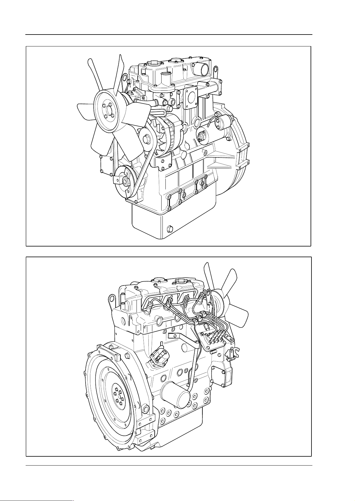
Engine views
400 Series
H1029
H1030
6 Workshop Manual, TPD 1458E, issue 3 - Perkins Confidential: Green
Page 17
400 Series
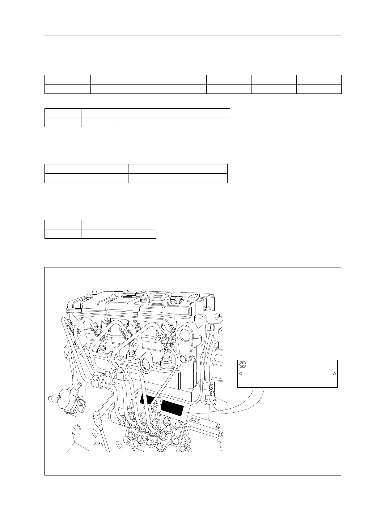
Engine identification
Engine build lists numbering system
The standard engine build list numbering code is defined as follows:
Code I II III IV V
Example HP TBA U 000001 D
Code I Engine build code
Code HH HL HP HR
Engine 403C-11 403C-15 404C-22 404C-22T
Code II engine build list
The build list increases numerically for both OEMS and distributors.
Code III country of manufacture
Code J U
Country of manufacture Made in Japan Made in U.K.
Code IV engine serial number
Individual serial number commencing with 000001 increasing numerically.
1
Code V year of manufacture
Code H J
Year 2001 2002
Perkins
LIST NO SERIAL NO TYPE
TYPE
H1031
Workshop Manual, TPD 1458E, issue 3 - Perkins Confidential: Green 7
Page 18
1
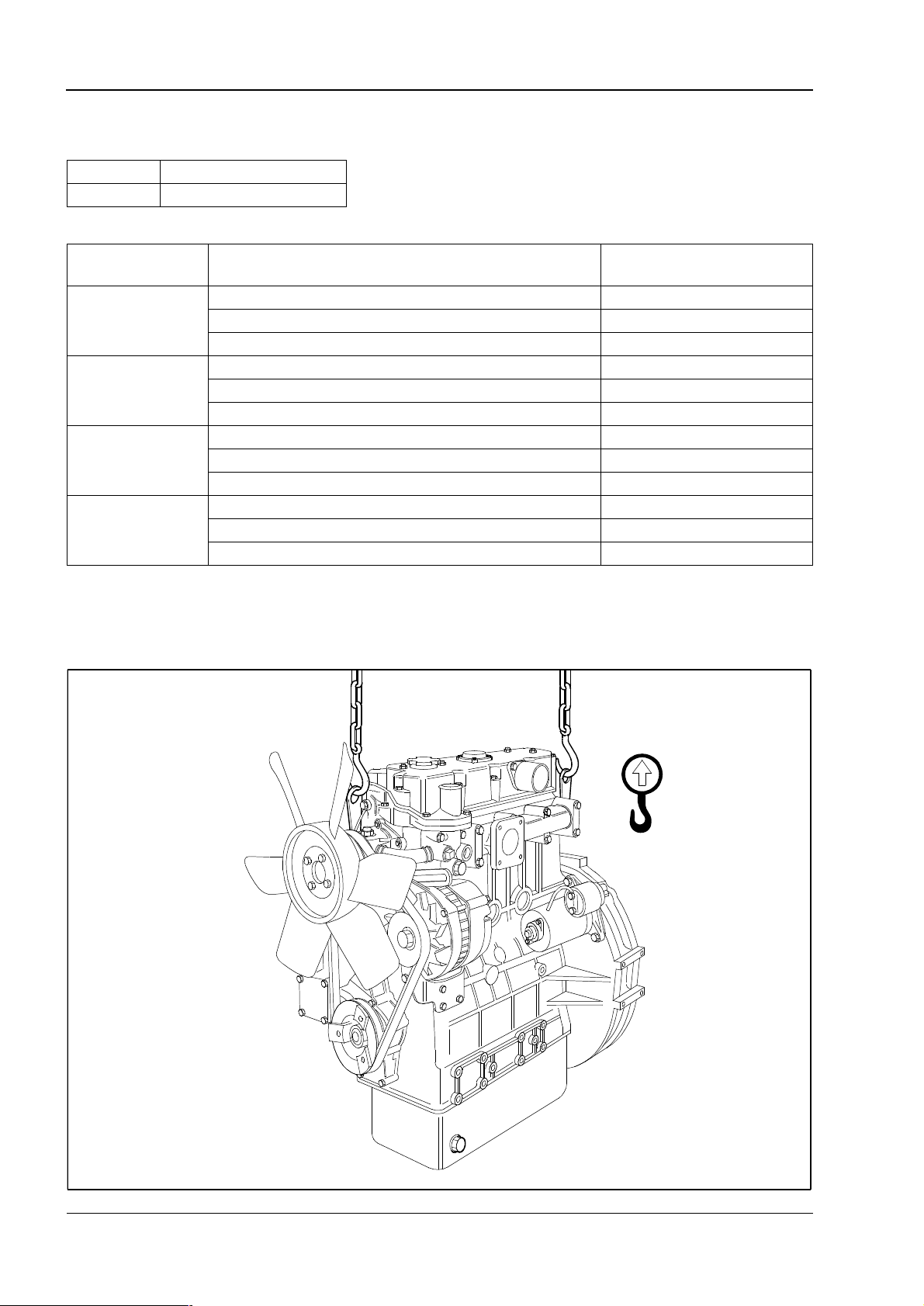
Engine lift equipment
Recomm en d ed torque : l if ting eye bolt s
Engine Nm (lbf ft) kgf m
All models 26 (19) 2,6
Maximum engine weights
400 Series
Engine Engine specification Maximum engine
weights (dry)
Long flywheel housing speci fic at ion 114 kg
403C-11
403C-15
404C-22
404C-22T
(1) Engine may alter with final specification.
Short flywheel housing specification 96 kg
Backplate specification 87 kg
Long flywheel housing speci fic at ion 176 kg
Short flywheel housing specification 154 kg
Backplate specification 150 kg
Long flywheel housing speci fic at ion 220 kg
Short flywheel housing specification 196 kg
Backplate specification 184 kg
Long flywheel housing speci fic at ion 230 kg
Short flywheel housing specification 206 kg
Backplate specification 194 kg
(1)
H1032
8 Workshop Manual, TPD 1458E, issue 3 - Perkins Confidential: Green
Page 19

400 Series
2
Specifications 2
Basic engine data
Engine model 403C-11 403C-15 404C-22 404C-22T
Engine build code HH HL HP HR
Number of cy linde rs 3 3 4 4
Cylinder
arrangement
Cycle Four stroke
Direction of rotation Clockwise from the front
Induction system Naturally aspirated Turbo charged
Combustion system Indirect injection
Nominal bore 77 mm (3.03 in) 84 mm (3.3 in)
Stroke 81 mm (3.19 in) 90 mm (3.5 in) 100 mm (3.9 in)
Compression ratio 23: 1 22.5: 1 23.3: 1
Cubic capacity 1,131 litres (69 in³) 1,496 litres (91 in³) 2,216 litres (135.2 in³)
Firing order 1, 2, 3 1, 2, 3 1, 3, 4, 2
Valve tip clearance (cold)
Inlet 0,2 mm (0.0078 in)
Exhaust 0,2 mm (0.0078 in)
Governor Mechanical all speed
Fuel injection Cassette type fuel injection pump
Electrical system 12 Volt
Lubricating oil
pressure relief valve
Lubricating oil
pressure switch
located on to p cover
Lubricating oil
pressure switch
located on cylinder
block oil rail
304 - 500 kPa 262 - 359 kPa 352 - 448 kPa
49,0 kPa 29,4 kPa
49,0 kPa 98,0 kPa
Vertical in line
Workshop Manual, TPD 1458E, issue 3 - Perkins Confidential: Green 9
Page 20

2
400 Series
Standard torques
Most of the torque tensions on the engine are standard. Special torque tensions are listed in the separate
specific torque tables. The standard torque tensions listed in the tables below can be used when a specific
torque is not necessary.
The torque tensions below apply to components lubricated lightly with clean engine oil before they are fitted.
Standard torques for setscrews and nuts
Coarse thread Fine thread
Thread size Strength
M 4
M5
M6
M8
M10
M12
M14
M16
8.8
11T
8.8
11T
8.8
11T
8.8
11T
8.8
11T
8.8
11T
8.8
11T
8.8
11T
Pitch
mm
0,7
0,8
1,0
1,25
1,5
1,75
2,0
2,0
Torque Torque Torque
Nm lbf ft kgf m Nm lbf ft kgf m
3
4
6
8
10
14
26
32
50
62
75
104
118
157
167
230
2
3
4
6
7
10
19
24
37
46
55
77
87
116
123
170
0,3
0,4
0,6
0,8
1,0
1,4
2,7
3,3
5,1
6,3
7,6
10,6
12,0
16,0
17,0
23,4
Pitch
mm
1,0
1,25
1,25
1,5
1,5
Torque Torque Torque
----
----
---30
35
56
66
84
113
132
167
175
245
22
26
41
49
62
83
97
123
129
181
3,0
3,6
5,7
6,7
8,6
11,5
13,5
17,0
17,8
25,0
Bolt strength Examples of applicable material
8.8
11T
S45C
SCM435
10 Workshop Manual, TPD 1458E, issue 3 - Perkins Confidential: Green
Page 21

400 Series
Special torques
Torque Nm (lbf ft) kgf m
Angleich 5 (3.6) 0,5
Atomiser 64 (47.2) 6,4
Atomiser pipes 23 (16.9) 2,3
Blanking plug rear of cylinder block 7 (5.1) 0,7
Crankshaft carrier to block 27 (19.9) 2,7
Connecting rod nuts 52 (38.3) 5,2
Crankshaft nut 303 (223.5) 30,3
Crankshaft sub assembly 52 (38.3) 5,2
Exhaust manifold 25 (18.4) 2,5
Flywheel 74 (54.5) 7,4
Fuel injection pump 15 (11) 1,5
Fuel injection pump leak off rail 7 (5.1) 0,7
Glow plug 18 (13.2) 1,8
Head setscrew 101 (74.5) 10,3
Leak off rail 27 (19.9) 2,7
Lift pump banjo 12 (8.8) 1,2
Lift pump mounting setscrew 6 (4.4) 0,6
Oil pipe 12 (8.8) 1,2
Oil strainer 10 (7.3) 1,0
Relief valve 64 (47.2) 6,4
Timing case 10 ( 7.3) 1,0
Rocker assembly nuts 33 (24.3) 3,3
Rocker cover 14 (10.3) 1,4
Electrical shut off solenoid 18 (13.2) 1,8
Sump drain plug 35 (25.8) 3,5
Temperature switch 27 (19.9) 2,7
Thermostat setscrew 14 (10.3) 1,4
2
Workshop Manual, TPD 1458E, issue 3 - Perkins Confidential: Green 11
Page 22
2
400 Series
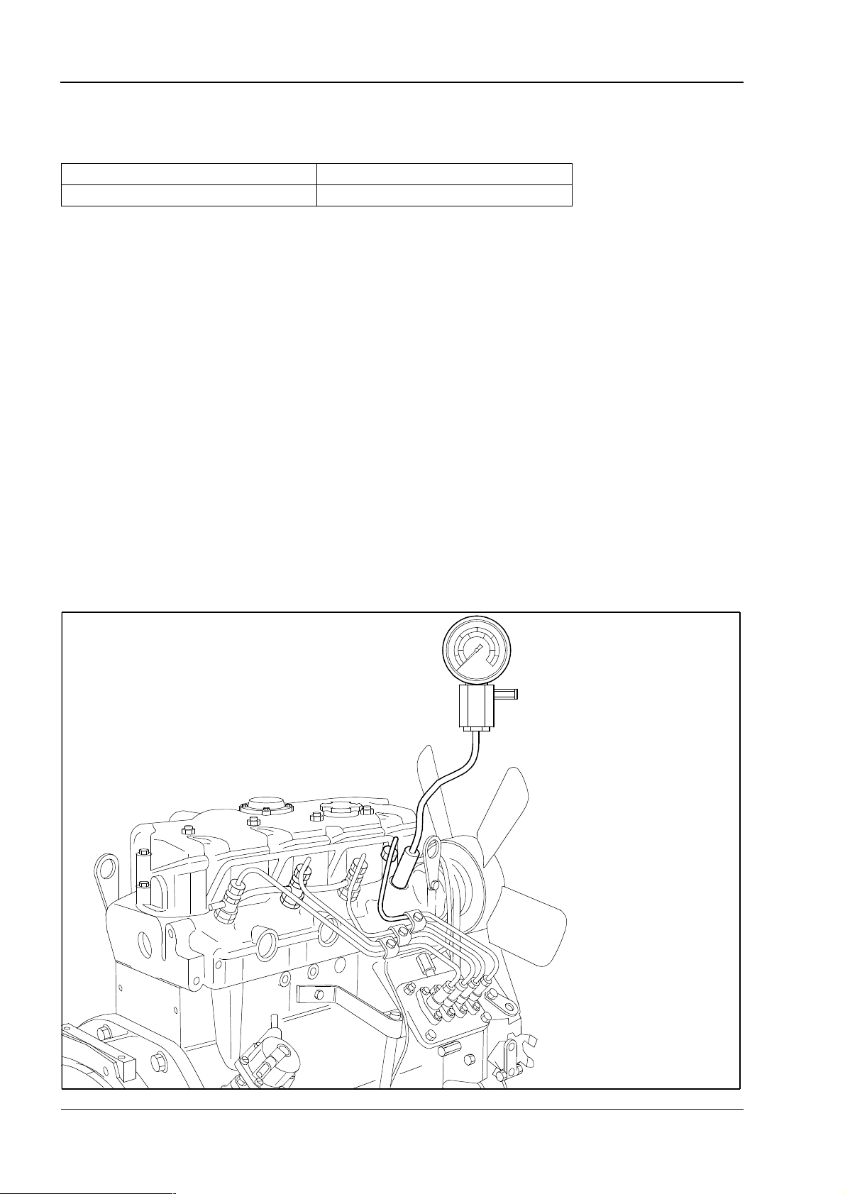
Compression test data
Many factors affect compression pressures, the battery, starter motor condition, ambient conditions and the
type of gauge used can give a wide variation of results for a given engine.
Standard value To be repaired
>2940 kPa (426.6 lbf / in²) @ 250 rpm <2450 kPa (355.5 lbf / in²) @ 250 rpm
Compression tests should only be used to compare between cylinders of an engine. If one or more cylinders
vary by more than 350 kPa (50 lbf / in²) then those cylinders may be faulty.
Compression tests should not be the only method used to show the condition of an engine, but they should be
used together with other symptoms and tests.
How to do a compression test
Note: Before the compression test, ensure that the battery is in good condition and fully charged. Also ensure
the starter motor is in good condition.
1 Ensure that the valve tip clearances are set correctly.
2 Remove the atomisers, see Operation 11-1.
3 Fit a suitable gauge into the atomiser hole of the cylinder to be tested.
4 Disconnect the stop solenoid or put the stop solenoid in the no fuel position. Operate the starter motor and
record the pressure indicated on the gauge.
Caution: Do not remove the stop solenoid as this will allow the engine to start.
5 Repeat for each cylinder.
H1033
12 Workshop Manual, TPD 1458E, issue 3 - Perkins Confidential: Green
Page 23
400 Series
3
Cylinder head assembly 3
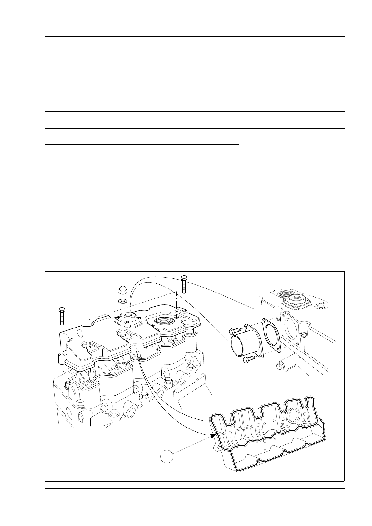
Rocker cover and inlet manifold
To remove and to fit Operation 3-1
Engine Torque Nm (lbf ft) kgf m
403C-11
403C-15
404C-22
404C-22T
Notes:
l An ‘O’ ring (1) is fitted in the groove in the rocker cover.
l Inspect the ‘O’ ring and renew if necessary.
Cap nut 11 (8.1) 1,1
Setscrew 11 (8.1) 1,1
Cap nut 14 (10.3) 1,4
Setscrew 14 (10.3) 1,4
1
H1034
Workshop Manual, TPD 1458E, issue 3 - Perkins Confidential: Green 13
Page 24
3
400 Series
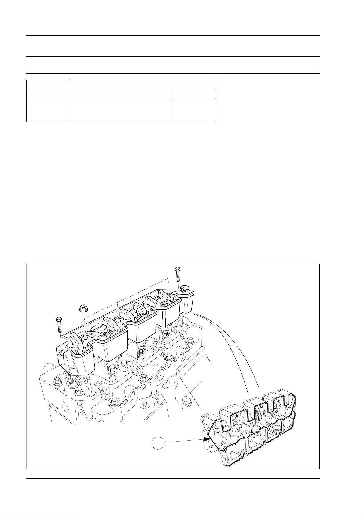
Rocker ass embly
To remove and to fit Operation 3-2
Engine Torque Nm (lbf ft) kgf m
403C-11 Rocker assembly nuts 23 (17.0) 2,3
403C-15
404C-22
404C-22T
Caution: Ensure that the valve stem caps are on the valve stems and the pushrods are located in the rockers
after assembly.
Note: An ‘O’ ring (1) is fitted in the groove in the rocker assembly.
Rocker assembly nuts 33 (24.3) 3,3
1
H1035
14 Workshop Manual, TPD 1458E, issue 3 - Perkins Confidential: Green
Page 25

400 Series
3
To dismantle and to assemble Operation 3-3
Engine Torque Nm (lbf ft) kgf m
All models Tappet adjustment nut 14 (10.3) 1,4
Use a suitable puller to extract the rocker shaft.
Note: Remember the position of the recess (1) for assembly.
1
H1036
Workshop Manual, TPD 1458E, issue 3 - Perkins Confidential: Green 15
Page 26
3
s
400 Series
To inspect Operation 3-4
Rockershaft diameter
Engine
403C-11
403C-15
404C-22
404C-22T
Rocker shaft to rocker lever clearance
Engine
403C-11
403C-15
404C-22
404C-22T
11,65 - 11,67 (0.4587 - 0.4595) 11,57 (0.4555)
14,95 - 14,97 (0.5886 - 0.5894) 14,87 (0.5854)
0,032 - 0,068 (0.00126 - 0.00268) 0,2 (0.008)
0,030 - 0,093 (0.00120 - 0.00366) 0,2 (0.008)
Standard Service limit
Standard Service limit
Diameter mm (in)
Clearance mm (in)
H1037
16 Workshop Manual, TPD 1458E, issue 3 - Perkins Confidential: Green
Page 27
400 Series
3
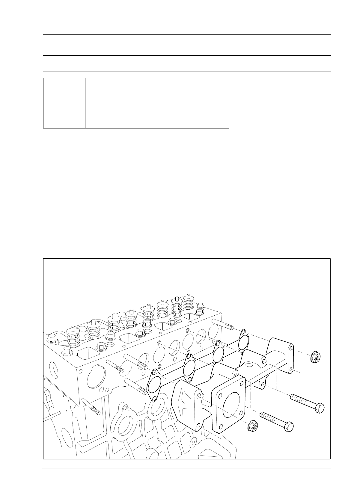
Exhaust manifold and gasket
To remove and to fit Operation 3-5
Engine Torque Nm (lbf ft) kgf m
403C-11
403C-15
404C-22
404C-22T
Setscrew 9,8 (7.2) 0,9
Nuts 9,8 (7.2) 0,9
Setscrew 25 (18.4) 2,5
Nuts 25 (18.4) 2,5
H1038
Workshop Manual, TPD 1458E, issue 3 - Perkins Confidential: Green 17
Page 28
3
400 Series
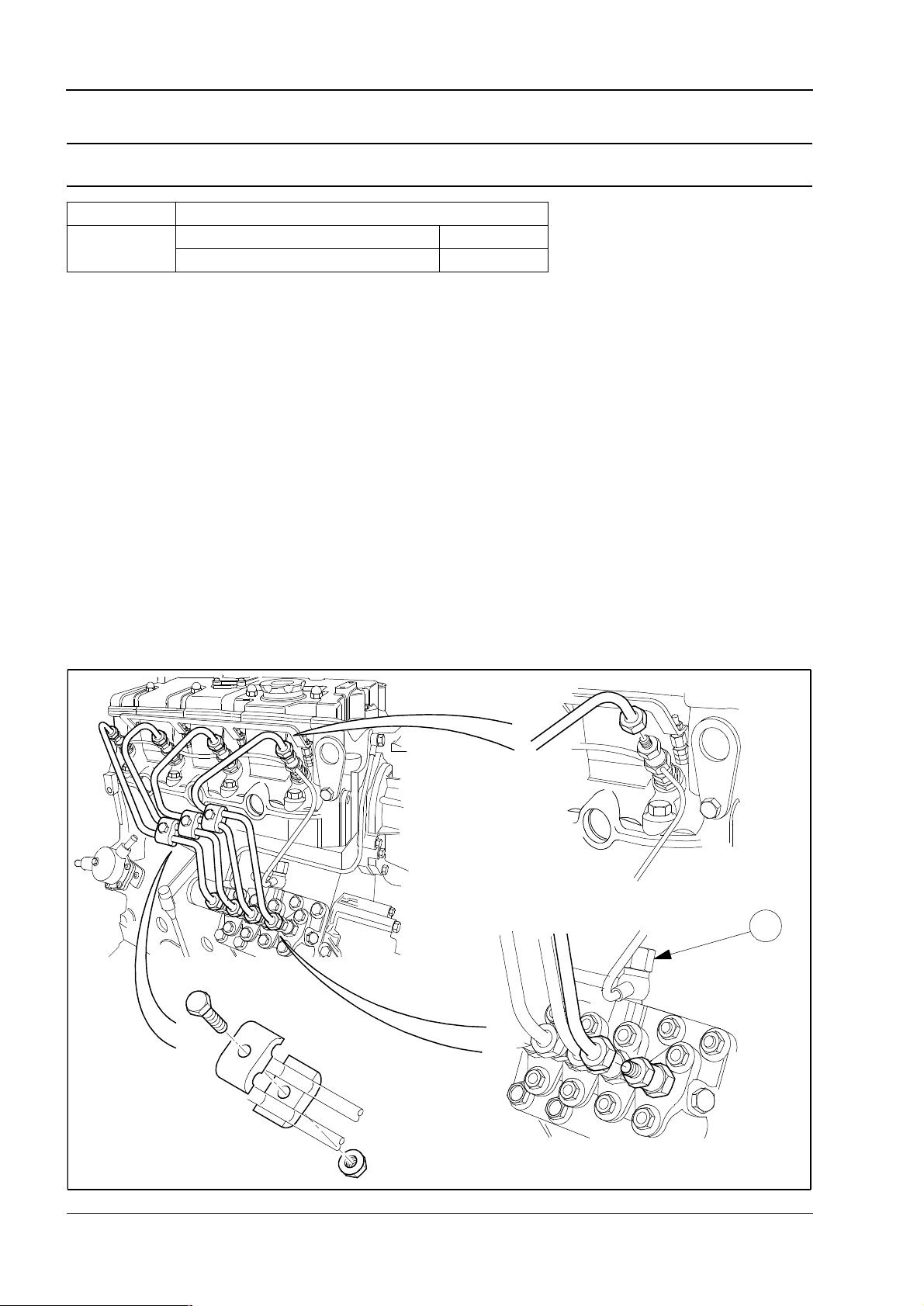
Fuel injection pipes / fuel return pipes
To remove and to fit Operation 3-6
Engine Torque Nm (lbf ft) kgf m
All models
Fuel injection pipe 23 (16.9) 2,3
Banjo bolt (1) 2,5 (3.2) 0,25
1
H1039
18 Workshop Manual, TPD 1458E, issue 3 - Perkins Confidential: Green
Page 29
400 Series
3
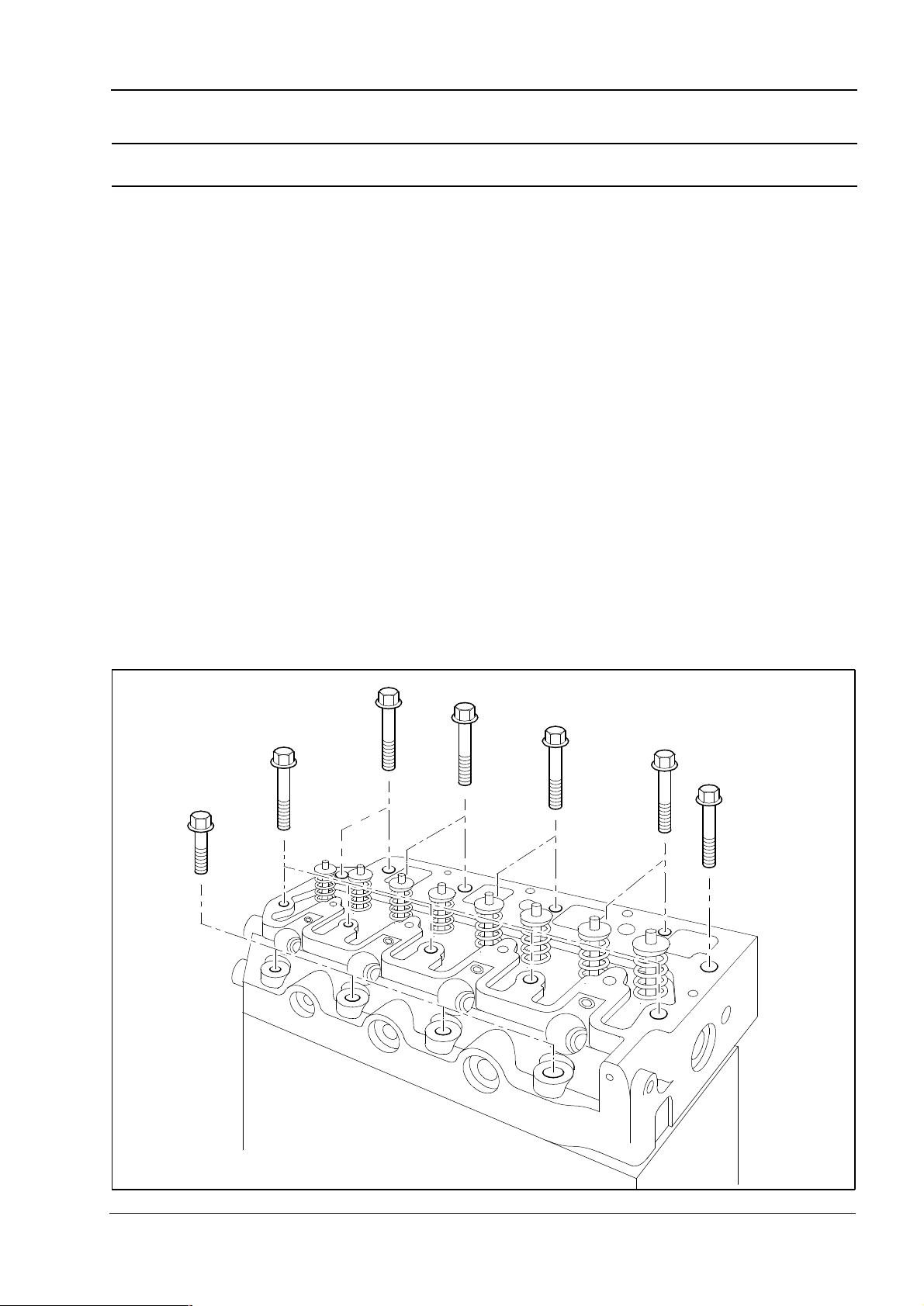
Cylinder head setscrews
To remove and to fit Operation 3-7
Note: If it is necessary to replace the cylinder head the fuel adjustment screw must not be altered from the
original setting. The maximum no load speed must be checked after assembly.
H1040
Workshop Manual, TPD 1458E, issue 3 - Perkins Confidential: Green 19
Page 30
3
400 Series
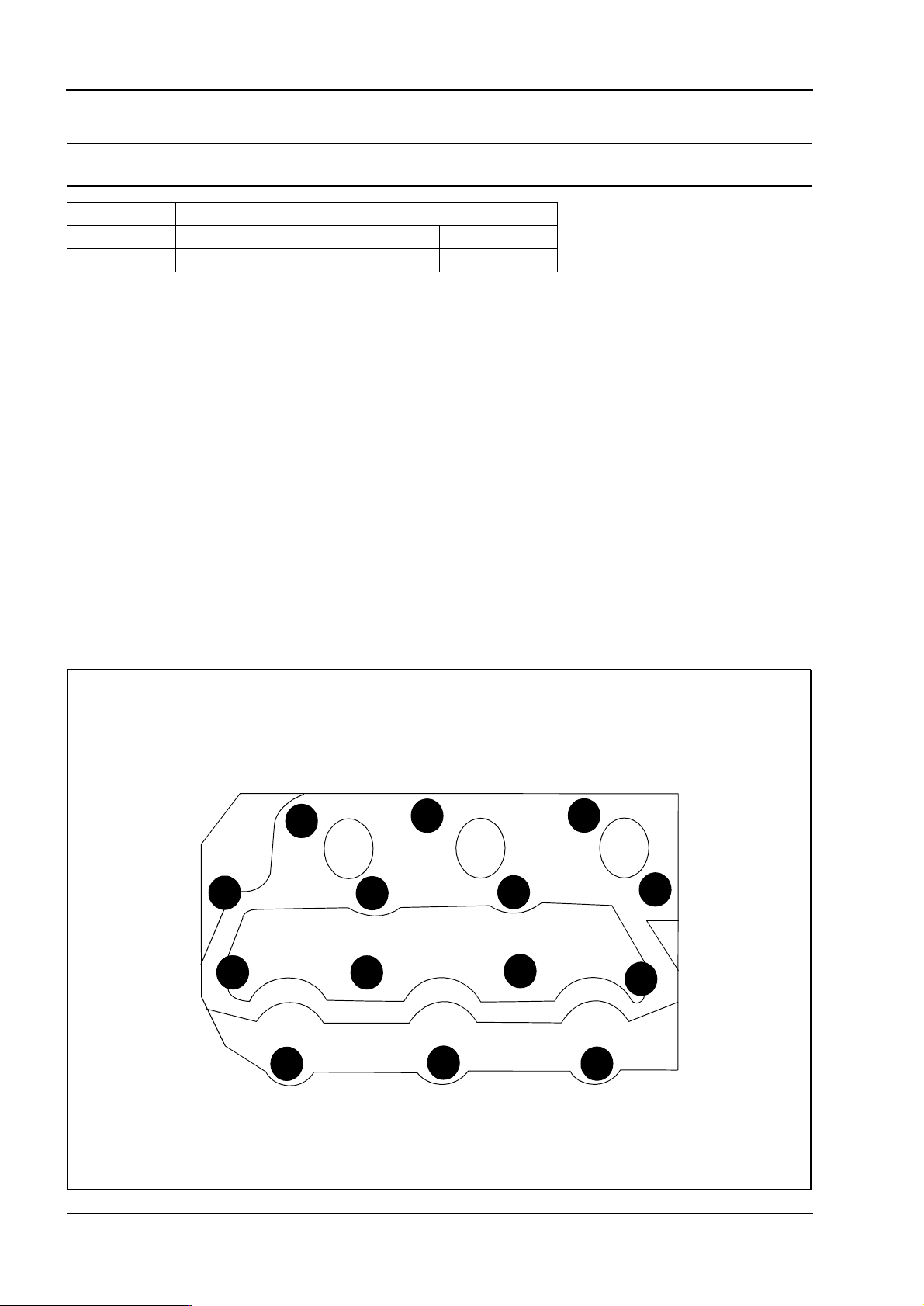
Cylinder head
Tightening sequence 403C-11 and 403C-15 Operation 3-8
Engine Torque Nm (lbf ft) kgf m
403C-11 Cylinder head setscrews 51 (37.6) 5,2
403C-15 Cylinder head setscrews 101 (74.5) 10,3
Notes:
l All torques should be checked again after tightening.
l On assembly lubricate cylinder head setscrews with clean oil.
11
5
8
14
20 Workshop Manual, TPD 1458E, issue 3 - Perkins Confidential: Green
1
4
9
3
2
10
13
7
6
12
H1041
Page 31

400 Series
3
Tightening sequence 404C -22 and 404C-22T Operation 3-9
Engine Torque Nm (lbf ft) kgf m
404C-22
404C-22T
Notes:
l All torques should be checked again after tightening.
l On assembly lubricate cylinder head setscrews with clean oil.
Cylinder head setscrews 101 (74.5) 10,3
12 4
16
15
11
Workshop Manual, TPD 1458E, issue 3 - Perkins Confidential: Green 21
8
7
3
1
2
513
9
10
6
17
18
14
H1042
Page 32

3
400 Series
Cylinder head gasket
To remove and to fit Operation 3-10
Align the gasket on the dowels in the cylinder block.
Cautions:
l The gasket must only be fitted with the markings (1) facing up.
l When fitting a new gasket it must be replaced with a gasket of the same thickness as originally fitted. The
gasket thickness can be identified by the part number that is stamped on the gasket.
l The correct piston height must be maintained to prevent damage to the pistons and valves and ensure that
the engine conforms to emission legislation.
Note: Always fit dry.
1
n
a
e
l
c
n
U
d
n
A
H1043
22 Workshop Manual, TPD 1458E, issue 3 - Perkins Confidential: Green
Page 33

400 Series
3
To select the correct thickness of cylinder head gasket Operation 3-11
Caution: If the correct piston height above or below the cylinder block is not obtained, damage to the engine
can occur. The difference between the highest and the lowest piston height must not exceed 0.1 mm.
1 Put the piston height tool (A) on the face of the cylinder block and rotate the gauge dial to the zero position.
2 Rotate the crankshaft until the piston crown is approximately at top dead centre (TDC).
3 Carefully put the tool over the top of the piston with the plunger of the gauge in contact with the piston above
the axis of the gudgeon pin.
4 Rotate the crankshaft to ensure that the piston is at the highest position and make a note of the gauge
indication.
Notes:
l If the cylinder block, crankshaft, connecting rods or pistons are changed the piston height will have to be
checked and the correct thickness gasket used.
l If the original piston is used, ensure that it is assembled to the correct connecting rod and is used in the
original cylinder.
Cylinder head gasket selection
Engine Protrusion above cylinder block top face Gasket thickness
403C-11
403C-15
Engine Protrusion below cylinder block top face Gasket thickness
404C-22
404C-22T
0,55 to 0,64 1,2 mm
0,65 to 0,75 1,3 mm
0,60 to 0,69 1,3 mm
0,70 to 0,79 1,4 mm
-0,45 to -0,30 0,4 mm
-0,29 to -0,20 0,5 mm
H1044
Workshop Manual, TPD 1458E, issue 3 - Perkins Confidential: Green 23
Page 34

3
400 Series
Valve and valve spring
To remove and to fit Operation 3-12
Special tools
Description Part number
Valve spring remover 21825663
Valve stem seal replacer 21825623
Notes:
l The oil seal for the inlet valve stem is identified by a silver garter spring.
l The oil seal for the exhaust valve stem is identified by a black garter spring (not shown) with the letters “EX”
on the garter.
Warning! Safety glasses must be worn for this operation.
H1045
24 Workshop Manual, TPD 1458E, issue 3 - Perkins Confidential: Green
Page 35

400 Series
3
To inspect - valve spring Operation 3-13
Visually inspect the valve spring for damage.
Use a spring tester to check spring force and free length. Renew the spring if it is outside the service limit.
Engine
Free length (1) mm (in)
Standard Service limit
All models 35,0 (1.378) 33,5 (1.319)
Spring rate when compressed to 30,4 mm (1.197 in)
Engine
N (lbf) kgf
Standard Service limit
All models 79 (17.8) 8,1 68,6 (15.4) 7,0
1
New
Worn
H1046
Workshop Manual, TPD 1458E, issue 3 - Perkins Confidential: Green 25
Page 36

3
400 Series
To inspect - valve stem and thickness of valve head Operation 3-14
Use a micrometer to check the valve stem diameters at positions 1, 2 and 3, if less than the service limit, renew.
Check the valve stem for wear or damage, if outside the service limit, renew.
Inlet valve
Engine
Standard Service limit
Diameter mm (in)
All models 6,955 - 6,970 (0.27382 - 0.27441) 6,89 (0.271)
Exhaust valve
Engine
Standard Service limit
Diameter mm (in)
All models 6,940 - 6,950 (0.27323 - 0.27362) 6,84 (0.269)
Valve head thickness
Engine
Thickness mm (in)
Standard Service limit
All models 0,925 - 1,075 (0.03642 - 0.04232) 0,5 (0.020)
If the valve head thickness (4) is less than the service limit, renew the valve.
1
1
4
2
2
3
3
H1047
26 Workshop Manual, TPD 1458E, issue 3 - Perkins Confidential: Green
Page 37

400 Series
3
Cylinder head to valve stem clearance
To inspect Operation 3-15
Check the clearance (3) between the valve stem and the cylinder head. If the clearance is greater than the
service limit, the valves must be checked for wear, see Operation 3-14, If the valves are within service limits,
renew the cylinder head.
1 Put a new valve in the valve guide.
2 Put a dial test indicator with a magnetic base (1) onto the face of the cylinder head.
3 With the valve lifted 15,0 mm (0.6 in) and the gauge (2) in contact with the edge of the valve head, move the
valve radially away from the gauge. With the head in this position, set the gauge to ‘0’.
4 Move the valve radially across the axis of the cylinder head towards the gauge. Make a note of the reading
on the gauge if the reading is greater than the service limit, renew the cylinder head.
Maximum permissible clearances with a valve lift of 15 mm (0.6 in).
Inlet valve
Engine Clearance mm (in) standard Service limit
403C-11 0,025 - 0,052 (0.0010 - 0.0020) 0,2 (0.008)
403C-15, 404C-22 and 404C-22T 0,030 - 0,060 (0.0012 - 0.0024) 0,2 (0.008)
Exhaust valve
Engine Clearance mm (in) standard Service limit
403C-11 0,045 - 0,072 (0.0020 - 0.0030) 0,25 (0.010)
403C-15, 404C-22 and 404C-22T 0,050 - 0,075 (0.0020 - 0.0030) 0,25 (0.010)
1
2
3
H1048
Workshop Manual, TPD 1458E, issue 3 - Perkins Confidential: Green 27
Page 38

3
400 Series
Cylinder head
To inspect Operation 3-16
Maximum regrind limit mm (in)
Distortion Maximum service limit Maximum regrind
0,05 (0.002) or less 0,12 (0.005) 0,15 (0.006)
Use a straight edge and feeler gauge to check the six positions for distortion.
Caution: Do not grind beyond the maximum limit.
1
3
5
2
28 Workshop Manual, TPD 1458E, issue 3 - Perkins Confidential: Green
6
4
H1049
Page 39

400 Series
3
Valve seat width
#
To inspect and to co rrect Operation 3-17
Special tools
Description Part number
Valve seat cutter 27610030
Inlet valve Exhaust valve
Engine
403C-11 1,70 - 2,10 (0.0670 - 0.0830) 2,5 (0.098) 1,70 - 2,10 (0.0670 - 0.0830) 2,5 (0.098)
403C-15 1,66 - 1,87 (0.0653 - 0.0736) 2,5 (0.098) 1,66 - 1,73 (0.0653 - 0.0681) 2,5 (0.098)
404C-22
404C-22T
1,50 - 2,00 (0.0591 - 0.0790) 2,5 (0.098) 1,94 - 2,16 (0.0764 - 0.0850) 2,5 (0.098)
If the contact face (1) of the valve seat is more than the service limit, check the valve stem for wear, see
Operation 3-14 and the cylinder head to valve stem clearance, see Operation 3-15. If greater than the service
limit, use a seat cutter of 45° to correct the seat.
If the valve stem clearance exceeds the service limit, renew the valve.
Clearance mm (in) Clearance mm (in)
Standard Service limit Standard Service limit
If the bore in the cylinder head for the valves is worn, replace the cylinder head. If the valve seat in the cylinder
head is damaged or worn, cut a new seat if the valve depth will remain within tolerance.
1
45°
Contact
Width
H1050
Workshop Manual, TPD 1458E, issue 3 - Perkins Confidential: Green 29
Page 40

3
400 Series
Valve depth
To check Operation 3-18
If the valve depth (1) is greater than the service limit, use a new valve to check the valve depth.
If the depth still exceeds the service limit, renew the cylinder head. If the depth is within the service limit renew
the valves.
Engine
403C-11 0,65 - 0,95 (0.0256 - 0.0374) 0,85 - 1,15 (0.0335 - 0.0453) 1,8 (0.071)
403C-15 0,85 - 1,15 (0.0335 - 0.0453) 0,85 - 1,15 (0.0335 - 0.0453) 1,8 (0.071)
404C-22
404C-22T
0,65 - 0,95 (0.0256 - 0.0374) 0,65 - 0,95 (0.0256 - 0.0374) 1,8 (0.071)
Inlet standard Exhaust standard Service limit
Depth mm (in)
1
H1051
30 Workshop Manual, TPD 1458E, issue 3 - Perkins Confidential: Green
Page 41

400 Series
3
To lap the contact face of the valve seat Operation 3-19
Use the valve seat cutter to obtain the correct seat contact width and seat recess on a new cylinder head, use
a valve lapping tool and lapping compound to finish.
H1052
Workshop Manual, TPD 1458E, issue 3 - Perkins Confidential: Green 31
Page 42

3
400 Series
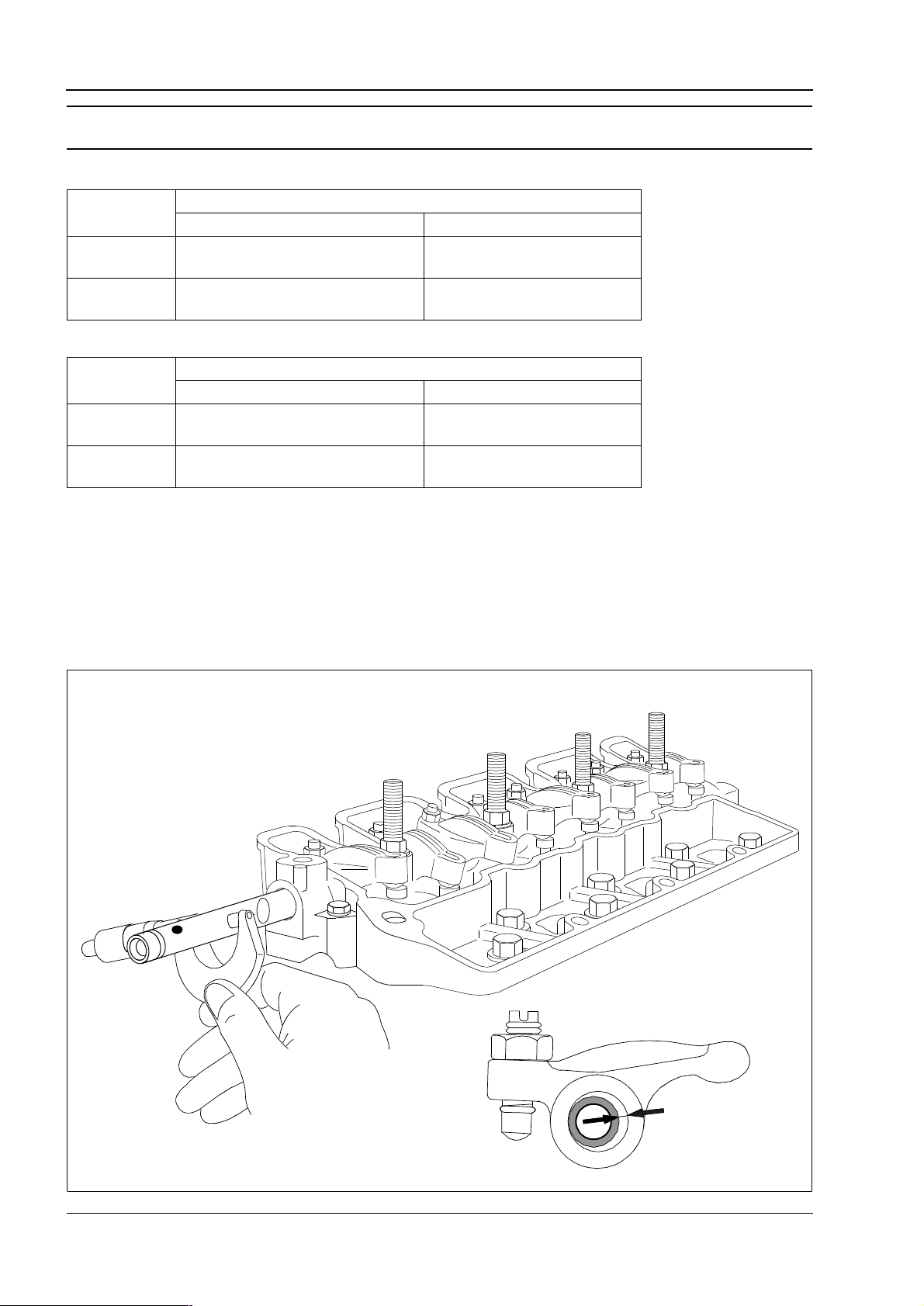
Valve tip clearance
To check and to adjust Operation 3-20
The valve adjustment sequence is viewed from the front of the engine.
Rotate the crankshaft clockwise when viewed from the front.
Caution: Only adjust the valve clearances when the engine is cold.
Engine Valve overlap Adjust valves
403C-11
403C-15
404C-22
404C-22T
No. 1 Cylinder 3 and 6
No. 2 Cylinder 2 and 5
No. 3 Cylinder 1 and 4
No. 4 Cylinder 1 and 2
No. 2 Cylinder 5 and 6
No. 1 Cylinder 7 and 8
No. 3 Cylinder 3 and 4
Valve tip clearance (cold)
Inlet 0,2 mm (0.0078 in)
Exhaust 0,2 mm (0.0078 in)
Torque Nm (lbf ft) kgf m
Tappet adjustment nut 14 (10.3) 1,4
H1053
32 Workshop Manual, TPD 1458E, issue 3 - Perkins Confidential: Green
Page 43

400 Series
4
Piston and connecting rod assemblies 4
Big end bearing and cap
To remove and to fit Operation 4-1
Engine Torque Nm (lbf ft) kgf m
403C-11 Nut 32 (23.6) 3,3
403C-15, 404C-22 and 404C-22T Nut 52 (38.3) 5,2
Standard clearance Service limit
0,1 - 0,3 mm (0.004 - 0.012 in) 0,7 mm (0.276 in)
Caution: Ensure that the connecting rod bolts (2) do not damage the crankshaft when the connecting rod is
removed or fitted.
Notes:
l The connecting rods and caps are numbered matched pairs and must be kept together when removed from
the engine. The numbers (1) must be aligned when assembled.
l The piston and connecting rods are matched to a cylinder, record the position of each connecting rod and
piston for correct assembly. After the connecting rods are fitted check for axial movement.
l The fuel adjustment screw must not be altered from the original setting. The maximum no load speed must
be checked after assembly.
2
1
H1054
Workshop Manual, TPD 1458E, issue 3 - Perkins Confidential: Green 33
Page 44

4
400 Series
Piston and connecting rod
To remove and to fit Operation 4-2
The Shibaura name on the inside of the piston must be facing the fuel pump on assembly.
To assemble the connecting rod assembly, see page 35.
1
H1055
34 Workshop Manual, TPD 1458E, issue 3 - Perkins Confidential: Green
Page 45

400 Series
4
To dismantle and to assemble Operation 4-3
The Shibaura (1) name (inside of the piston) must be aligned with the stamped number on the
connecting rod (1).
The numbers stamped on the connecting rods and caps must be the same and aligned.
C
A
M
A
3
2
1
1
H1056
Workshop Manual, TPD 1458E, issue 3 - Perkins Confidential: Green 35
Page 46

4
400 Series
Piston rings
To fit Operation 4-4
Any letters or markings on the surface of the ring will always be positioned on the top face (facing upwards).
Use a suitable piston ring expander to fit the piston rings.
1 Fit the spring of the oil control ring (6) in the bottom groove of the piston with the latch pin (1) inside both
ends of the spring. Fit the oil control ring (4) over the spring (6). Ensure that the ring gap is at 180° to the latch
pin.
2 Fit the second ring (3) with the taper face into the second groove, with the word "TOP" towards the top of
the piston.
New second rings have a green identification mark which must be on the left of the ring gap when the ring is
fitted and the piston is upright.
The second ring has a step (5) at the top inside edge of the tapered face.
3 Fit the top ring (2) with the word 'TOP' towards the top of the piston.
New top rings have a red identification mark which must be on the left of the ring gap when the ring is fitted
and the piston is upright.
4 Ensure that the ring gaps are 90° apart.
1
M
A
6
2
90°
3
4
M
A
90°
5
H1057
36 Workshop Manual, TPD 1458E, issue 3 - Perkins Confidential: Green
Page 47

400 Series
4
To measure the piston ring clearance Operation 4-5
Use a feeler gauge to measure the clearance between the piston ring groove and the piston ring. If the
clearance is greater than the service limit, use a new piston ring and check the clearance again.
If the clearance is within the service limit with a new piston ring, renew the piston rings. If the clearance is
outside the service limit with a new piston ring, renew the piston.
Note: The number 1 piston ring of the 404C-22T is of the ‘keystone’ design, therefore it is difficult to measure
the wear due to it’s position in the piston ring groove. When either number 2 ring or the oil control ring is outside
the service limit renew all rings.
Engine Torque Nm (lbf ft) kgf m Standard Service limit
0,06 - 0,10 mm
(0.0024 - 0.0039 in)
0,05 - 0,09 mm
(0.0020 - 0.0035 in)
0,02 - 0,06 mm
(0.0008 - 0.0024 in)
0,07 - 0,11 mm
(0.0028 - 0.0043 in)
0,04 - 0,08 mm
(0.0016 - 0.0032 in)
0,02 - 0,06 mm
(0.0008 - 0.0024 in)
0,04 - 0,08 mm
(0.0016 - 0.0032 in)
0,02 - 0,06 mm
(0.0008 - 0.0024 in)
0,25 (0.0098 in)
0,25 (0.0098 in)
0,15 (0.0059 in)
0,25 (0.0098 in)
0,25 (0.0098 in)
0,15 (0.0059 in)
0,25 (0.0098 in)
0,15 (0.0059 in)
403C-11
403C-15
404C-22
404C-22T
Number 1 ring
Number 2 ring
Oil control ring
Number 1 ring
Number 2 ring
Oil control ring
Number 2 ring
Oil control ring
H1058
Workshop Manual, TPD 1458E, issue 3 - Perkins Confidential: Green 37
Page 48

4
To measure the piston ring gap Operation 4-6
If the piston ring is worn or damaged, renew.
Piston ring gap
Clean the carbon from the top of the cylinder bore.
Insert the ring into the cylinder at right angles to the cylinder block and measure the gap with a feeler gauge.
If the gap is greater than the service limit, renew the piston ring.
Engine Ring number Standard Service limit
Number 1 ring 0,15 - 0,27 mm (0.0059 - 0.0106 in) 1,0 mm (0.039 in)
403C11
403C-15
404C-22
404C-22T
Number 2 ring 0,12 - 0,24 mm (0.0047 - 0.0094 in) 1,0 mm (0.039 in)
Oil control ring 0,20 - 0,35 mm (0.0079 - 0.0138 in) 1,0 mm (0.039 in)
Number 1 ring 0,20 - 0,35 mm (0.0079 - 0.0138 in) 1,0 mm (0.039 in)
Number 2 ring 0,20 - 0,40 mm (0.0079 - 0.0158 in) 1,0 mm (0.039 in)
Oil control ring 0,20 - 0,40 mm (0.0079 - 0.0158 in) 1,0 mm (0.039 in)
400 Series
à
38 Workshop Manual, TPD 1458E, issue 3 - Perkins Confidential: Green
á
H1059
Page 49

400 Series
4
Piston and connecting rod assemblies
To dismantle and to assemble Operation 4-7
Gudgeon pin
Check the outside diameter of the gudgeon pin. If it is less than the service limit, renew the gudgeon pin.
Engine Outside diameter Service limit
403C-11 20,996 - 21,002 mm (0.82660 - 0.82680 in) 20,98 mm (0.8260 in)
403C-15
404C-22
404C-22T
Engine Standard clearance Service limit
403C-11 -0,004 - +0,004 mm (-0.00016 - +0.00016 in) 0,02 mm (0.0008 in)
403C15
404C-22
404C-22T
27,996 - 28,000 mm (1.10220 - 1.10240 in) 27,98 mm (1.1016 in)
-0,001 - +0,007 mm (-0.00040 - +0.00030 in) 0,02 mm (0.0008 in)
Workshop Manual, TPD 1458E, issue 3 - Perkins Confidential: Green 39
Page 50

4
400 Series
Piston and piston ring
To inspect Operation 4-8
Piston
If the outer surface of the piston is damaged (cracked, scored, burning etc) renew.
Piston skirt
Check the larger diameter of the piston skirt (10 mm from bottom).
Check the inside diameter (thrust direction) of the cylinder. Calculate the clearance between the cylinder and
the piston. If the clearance is more than the service limit, or piston diameter is less than service limit, renew
the piston
Engine Cylinder diameter Service limit
403C-11 76,932 - 76,947 mm (3.02880 - 3.02940 in) 76,7 mm (3.020 in)
403C-15
404C-22
404C-22T
Engine Clearance between piston and cylinder Service limit
403C-11 0,0525 - 0,0865 mm (0.00210 - 0.00340 in) 0,25 mm (0.010 in)
403C-15
404C-22
404C-22T
83,948 - 83,963 mm (3.30503 - 3.30562 in) 83,7 mm (3.295 in)
0,0380 - 0,0720 mm (0.00150 - 0.00283 in) 0,25 mm (0.010 in)
40 Workshop Manual, TPD 1458E, issue 3 - Perkins Confidential: Green
Page 51

400 Series
4
Connecting rod
To inspect Operation 4-9
Engine Standard Service limit
All models
The large and small end bores must be parallel with each other within the limits of ± 0,31 mm (0.008 in)
measured 100 mm (3.397 in) each side of the connecting rods axis on a test mandrel.
Check the small end bush for wear or for other damage and renew it if necessary.
Check the fit of the gudgeon pin in the small end bush and check the gudgeon pin for wear.
Distortion for 100 mm (3.937 in) < 0,08 mm (0.0031 in) 0,20 mm (0.0079 in)
Parallel for 100 mm (3.937 in) < 0,05 mm (0.0020 in) 0,15 mm (0.0059 in)
± 0,08 mm
(0,0031 in)
100 mm
(3.937 in)
100 mm
(3.937 in)
± 0,08 mm
(0,0031 in)
H1060
Workshop Manual, TPD 1458E, issue 3 - Perkins Confidential: Green 41
Page 52

4
400 Series
Connecting rod bearing clearance
To check Operation 4-10
To check the clearance between the crankshaft bearing journal and the bearing cap.
1 Clean the bearing surfaces and the exposed half of the crankshaft journal.
2 Fit the bearing caps and tighten the bearing cap to torque.
3 Remove the bearing cap of the clearance to be checked.
4 Place a piece of Plastigauge ® across the full width of the bearing surface on the crankshaft journal, fit the
bearing cap and tighten the bearing cap setscrew to the specified torque.
5 Remove the bearing cap but do not move the Plastigauge ®.
6 Use the Plastigauge ® envelope to measure the widest point of the Plastigauge ®. This reading indicates
the bearing clearance in thousandths of an inch.
7 If the bearing clearance is not within the specifications the crankshaft must be reground and undersize
bearings fitted.
Engine Torque Nm (lbf ft) kgf m
403C-11 Bearing carrier setscrew 23 (16.9) 2,3
403C-15, 404C-22 and 404C-22T Bearing carrier setscrew 52 (38.3) 5,2
Engine Journals Standard clearance Service limit
403C-11
403C-15, 404C-22 and 404C-22T All 0,035 - 0,085 mm (0.00138 - 0.00335 in) 0,20 mm (0.0079 in)
1.0
2.0
2.5
3.0
4.0
PLASTIGAUGE
5.0
6.0
7.0
1 and 2 0,039 - 0,092 mm (0.00150 - 0.00360 in) 0,20 mm (0.0079 in)
3 0,029 - 0,082 mm (0.00110 - 0.00320 in) 0,20 mm (0.0079 in)
INCH
H1066
42 Workshop Manual, TPD 1458E, issue 3 - Perkins Confidential: Green
Page 53

400 Series
4
Small end bush
To remove and to fit Operation 4-11
Calculate the clearance between the small end bush and the gudgeon pin. if the clearance is greater than the
service limit, renew the bush.
Engine Clearance mm (in) Service limit mm (in)
403C-11 0,010 - 0,025 (0.00040 - 0.00099) 0.08 (0.0031)
403C-15
404C-22
404C-22T
0,010 - 0,025 (0.00040 - 0.00099) 0,10 (0.0040)
H1061
Workshop Manual, TPD 1458E, issue 3 - Perkins Confidential: Green 43
Page 54

This page is intentionally blank
Page 55

400 Series
5
Crankshaft assembly 5
Crankshaft pulley
To remove and to fit Operation 5-1
Engine Torque Nm (lbf ft) kgf m Special tools Part number
403C-11 Crankshaft nut 123 (90.7) 12,5
403C-15
404C-22
404C-22T
Note: Store the key (1) in a safe place until assembly.
Crankshaft nut 304 (224.2) 30,9
Crankshaft pulley remover 21825619
1
H1062
Workshop Manual, TPD 1458E, issue 3 - Perkins Confidential: Green 45
Page 56

5
400 Series
Crankshaft retaining bolts and crankshaft
To remove and to fit Operation 5-2
Engine Torque Nm (lbf ft) kgf m
403C-11
403C-15
404C-22
404C-22T
Cautions:
l Ensure that the lubricating oil pressure relief valve has been removed before the crankshaft is removed or
fitted.
l Ensure that the oil ways in the bearings align with the oil ways in the cylinder block.
Remove the bearing holder setscrews (1) and lift the crankshaft assembly out vertically.
Note: If the crankshaft or crankshaft bearings are replaced the fuel adjustment screw must not be altered from
the original setting. The maximum no load speed must be checked after assembly.
Crankshaft bearing holder setscrew 27 (19.9) 2,7
Crankshaft bearing holder to block (allen screws) 27 (19.9) 2,7
Crankshaft bearing holder setscrew 52 (38.3) 5,2
Crankshaft bearing holder to block (allen screws) 27 (19.9) 2,7
1
H1063
46 Workshop Manual, TPD 1458E, issue 3 - Perkins Confidential: Green
Page 57

400 Series
556
5
Crankshaft
To inspect for deflection Operation 5-3
1 Support the crankshaft on V-blocks.
2 Position a dial gauge on the crankshaft centre journal, and turn the crankshaft gradually by one full turn.
3 If the gauge reading is more than the service limit, renew or regrind the crankshaft.
Engine Deflection mm (in)
Standard Service limit
All models 0,03 or less (0.011) 0,06 (0.0023)
4 When the measured diameter is less than the service limit, regrind and use undersized bearings and bushes.
Crankshaft inspection
1 Check the oil seal contact face for damage or wear.
2 Check oil holes for clogging.
3 Check crankshaft journal (A4) and crank pin (A3) for stepped wear. Take measurements of diameters (A5-
A5) and (A6-A6) at positions (A1) and (A2). If the maximum difference between the measurements (stepped
wear) is more than the service limit of 0,05 mm (0.0019 in) then correction is required.
Grinding specification
When grinding the crankshaft, work with the following specifications:
Radius at pin / journal (B1) 3 mm (0.118 in) ± 0,2 mm (± 0.0078 in)
Finish precision (B2) 1.6Z (∇ ∇ ▼)
Radius around oil hole (B3) 2 mm (0.787 in) maximum / 5 mm (0.196 in) minimum
Note: Use No. 400 emery cloth for final polishing.
2
2
1
3
1
6
4
A
1
2 3
B
Workshop Manual, TPD 1458E, issue 3 - Perkins Confidential: Green 47
H1064
Page 58

5
400 Series
Crankshaft journal diameter
Engine Size Standard diameter Service limit
Standard 47,964 - 47,975 mm (1.88830 - 1.88880 in) 47,90 mm (1.8860 in)
403C-11
403C-15
404C-22
404C-22T
Undersize 0,25 mm (0.01 in) 47,714 - 47,725 mm (1.87850 - 1.87890 in) 47,65 mm (1.8750 in)
Undersize 0,50 mm (0.02 in) 47,464 - 47,475 mm (1.86870 - 1.86910 in) 47,40 mm (1.8660 in)
Standard 67,957 - 67,970 mm (2.67550 - 2.67597 in) 67,90 mm (2.6732 in)
Undersize 0,25 mm (0.01 in) 67,707 - 67,720 mm (2.66563 - 2.66614 in) 67,65 mm (2.6634 in)
Undersize 0,50 mm (0.02 in) 67,457 - 67,470 mm (2.65579 - 2.65630 in) 67,40 mm (2.6535 in) *
Crankshaft pin diameter
Engine Size Standard diameter Service limit
Standard 40,964 - 40,975 mm (1.61280 - 1.61320 in) 40,90 mm (1.6102 in)
403C-11
403C-15
404C-22
404C-22T
Undersize 0,25 mm (0.01 in) 40,714 - 40,725 mm (1.60290 - 1.60330 in) 40,65 mm (1.6003 in)
Undersize 0,50 mm (0.02 in) 40,464 - 40,475 mm (1.59310 - 1.59350 in) 40,40 mm (1.5905 in)
Standard 51,964 - 51,975 mm (2.04582 - 2.04626 in) 51,90 mm (2.0433 in)
Undersize 0,25 mm (0.01 in) 51,714 - 51,725 mm (2.03598 - 2.03641 in) 51,65 mm (2.0335 in)
Undersize 0,50 mm (0.02 in) 51,464 - 51,475 mm (2.02614 - 2.02660 in) 51,40 mm (2.0236 in) *
Note: If the diameter is less than the maximum undersize service limit (*), the crankshaft must be renewed.
48 Workshop Manual, TPD 1458E, issue 3 - Perkins Confidential: Green
Page 59

400 Series
5
Main bearings
To dismantle and to assemble Operation 5-4
Engine Torque Nm (lbf ft) kgf m
403C-11 Bearing holder setscrew 23 (16.9) 2,3
403C-15, 404C-22 and 404C-22T Bearing holder setscrew 52 (38.3) 5,2
End float
If the end float is greater than the service limit check the thrust washers for wear.
Note: Item (1) only used on 404C-22 and 404C-22T.
Engine Standard clearance Service limit
403C-11 0,10 - 0,30 mm (0.0040 - 0.0120 in) 0,50 mm (0.0197 in)
403C-15, 404C-22 and 404C-22T 0,10 - 0,40 mm (0.0040 - 0.0160 in) 0,50 mm (0.0197 in)
Engine Thrust washer thickness Service limit
403C-11
403C-15, 404C-22 and 404C-22T 2,95 - 3,00 mm (0.1161 - 0.1181 in) 2,80 mm (0.1102 in)
21,85 - 21,95 mm (0.8602 - 0.8641 in)
21,6 mm (0.8503 in)
1 Identify the location of bearing carriers on the crankshaft and mark before removal.
2 Install bearing carriers on the crankshaft, ensure that the lubricating oil holes align with the feed holes in the
cylinder block.
3 Check end float clearance.
Note: Ensure that the thrust washers are aligned correctly, fitted with their oil grooves towards the crankshaft.
4 Check the thrust washers for wear, poor contact or damage, if damaged renew.
1
H1067
Workshop Manual, TPD 1458E, issue 3 - Perkins Confidential: Green 49
Page 60

5
400 Series
Bearing holder
Centre bearing
1 Remove the bearing holder and inspect for peeling, melting, stepped wear and damage. if it is damaged
renew.
2 Use Plastigauge ® to measure the oil clearance (see Operation 4-10) between the crankshaft centre
journal and the bearing. If the oil clearance is greater than the service limit, renew the bearings or regrind
the centre journal and use undersize bearings.
Engine Standard oil clearance Service limit
403C-11 0,039 - 0,106 mm (0.00153 - 0.00401 in) 0,20 mm (0.0078 in)
403C-15
404C-22
404C-22T
Engine / Bearing size mm (in) Journal Centre crankshaft diameter mm (in)
403C-11
Standard
Undersize 0,25 (0.01)
Undersize 0,50 (0.02)
403C-15
Standard 1, 2, 3 67,957 - 67,970 (2.67550 - 2.67597)
Undersize 0,25 (0.01) 1, 2, 3 67,707 - 67,720 (2.66563 - 2.66614)
Undersize 0,50 (0.02) 1, 2, 3 67,457 - 67,470 (2.65579 - 2.65630)
404C-22 and 404C-22T
Standard 1, 2, 3, 4 67,957 - 67,970 (2.67550 - 2.67597)
Undersize 0,25 (0.01) 1, 2, 3, 4 67,707 - 67,720 (2.66563 - 2.66614)
Undersize 0,50 (0.02) 1, 2, 3, 4 67,457 - 67,470 (2.65579 - 2.65630)
0,044 - 0,102 mm (0.00150 - 0.00420 in) 0,20 mm (0.0078 in)
1, 2 47,965 - 47,975 (1.88830 - 1.88880)
3 47,954 - 47,965 (1.88800 - 1.88840)
1, 2 47,714 - 47,725 (1.87850 - 1.87890)
3 47,704 - 47,715 (1.87810 - 1.87850)
1, 2 47,464 - 47,475 (1.86870 - 1.86910)
3 47,454 - 47,465 (1.86250 - 1.86870)
50 Workshop Manual, TPD 1458E, issue 3 - Perkins Confidential: Green
Page 61

400 Series
6
Timing case and drive assembly 6
Timing cover
To remove Operation 6-1
Engine Special tools
Description Part number
403C-11 Front oil seal protector 21825620
403C-15, 404C-22 and 404C-22T Front oil seal protector 21825621
Cautions:
l If the timing case assembly or internal governor components are replaced the fuel adjustment screw should
not be adjusted. The maximum no load speed should be checked after assembly.
l The fuel injection pump, see Operation 11-3 and the keyway in the crankshaft must be removed before the
timing case is removed.
l Ensure that the stop lever arm (1) is held clockwise in tension for removal and assembly.
Note: If the timing case is renewed, a new emission label must be fitted as shown (2).
1 To remove the PTO cover, see Operation 6-9.
2 To remove and to fit the crankshaft pulley, see Operation 5-1.
1
2
3
Workshop Manual, TPD 1458E, issue 3 - Perkins Confidential: Green 51
H1068
Page 62

6
400 Series
To fit Operation 6-2
Engine Special tools
Description Part number
403C-11 Front oil seal protector 21825620
403C-15
404C-22
404C-22T
To fit
1 The fuel injection pump, see Operation 11-3 and the keyway in the crankshaft must be removed before the
timing case is fitted. Fit the front oil seal protector.
2 To fit the PTO cover, see Operation 6-9.
3 Ensure the oil pin (3) locates in the hole in the idler gear and that the stop lever arm (1) is held clockwise in
tension for removal and assembly.
4 Remove the oil seal protector (4) after fitting the timing cover. Fit the key into the key way in the crankshaft
nose.
5 To fit the crankshaft pulley, see Operation 5-1.
Note: If the timing case is renewed, a new emission label must be fitted as shown (2).
Front oil seal protector 21825621
Caution: If the timing case assembly or internal governor components are replaced the fuel adjustment screw
should not be adjusted. The maximum no load speed should be checked after assembly.
1
2
3
4
52 Workshop Manual, TPD 1458E, issue 3 - Perkins Confidential: Green
H1069
Page 63

400 Series
6
Angleich
To remove and to fit Operation 6-3
Engine Torque Nm (lbf ft) kgf m
403C-15,
404C-22
404C-22T
Notes:
l The internal setting for the Angleich must not be altered.
l Apply a little Loctite 275 to threads (2) before assembly.
l The Angleich is not fitted to the 403C-11 engine.
Angleich (1) 5 (3.6) 0,5
1
2
H1070
Workshop Manual, TPD 1458E, issue 3 - Perkins Confidential: Green 53
Page 64

6
400 Series
Slider
To remove and to fit Operation 6-4
The slider (2) must be fitted with the slot (4) held captive by the pin (3).
When fitting the timing case care must be taken to ensure correct alignment of the slider contact (1) with the
governor lever.
Caution: Incorrect alignment of the slider (2) on the pin (3) may result in the loss of engine speed control.
1
2
4
3
H1071
54 Workshop Manual, TPD 1458E, issue 3 - Perkins Confidential: Green
Page 65

400 Series
6
Camshaft retaining plate
To remove and to fit Operation 6-5
Engine Torque Nm (lbf ft) kgf m
All models Camshaft retainer plate setscrews 11 (8) 1,1
The camshaft retainer plate is fitted between the cylinder block and the camshaft gear. The camshaft retainer
plate is fastened by either two setscrews or a setscrew and an allen screw.
Note: If the camshaft assembly is replaced the fuel adjustment screw must not be altered from the original
setting. The maximum no load speed must be checked after assembly.
H1072
Workshop Manual, TPD 1458E, issue 3 - Perkins Confidential: Green 55
Page 66

6
400 Series
Camshaft and tappets
To remove and to fit Operation 6-6
Caution: Remove the lift pump see Operation 11-2 and the fuel injection pump see Operation 11-3 before
removing the camshaft.
Note: If the camshaft assembly is replaced the fuel adjustment screw must not be altered from the original
setting. The maximum no load speed must be checked after assembly.
Lubricate the tappets with clean lubricating oil before assembly.
1
H1073
56 Workshop Manual, TPD 1458E, issue 3 - Perkins Confidential: Green
Page 67

400 Series
6
Camshaft assembly
To inspect Operation 6-7
Height of cam for inlet and exhaust valves (1).
Engine Height mm (in)
Standard Service limit
403C-11 26,955 - 27,010 (1.06120 - 1.06340) 26,5 (1.0276)
403C-15, 404C-22 and 404C-22T 34,065 - 34,120 (1.34114 - 1.34330) 33,7 (1.3270)
Height of cam for fuel feed pump (2).
Engine Height mm (in)
Standard Service limit
403C-11 27.900 - 28,000 (1.09842 - 1.10240) 27,0 (1.0630)
403C-15, 404C-22 and 404C-22T 31,900 - 32,000 (1.25590 - 1.25984) 30,0 (1.1810)
Height of cam for fuel injection pump (3).
Engine Height mm (in)
Standard Service limit
403C-11 39,900 - 40,100 (1.57090 - 1.57870) 39,8 (1.5669)
403C-15, 404C-22 and 404C-22T 41,940 - 42,060 (1.65120 - 1.65590) 41,8 (1.6450)
1
3
2
H1074
Workshop Manual, TPD 1458E, issue 3 - Perkins Confidential: Green 57
Page 68

6
400 Series
Maximum fuel screw and maximum speed screw
Location Operation 6-8
Engine Torque Nm (lbf ft) kgf m
All models
Caution: The fuel adjustment setscrew must be set correctly for the engine to comply with emissions
legislation. This must only be carried out by an approved Perkins distributor.
Notes:
l The maximum fuel setscrew (1) and the maximum speed setscrew (2) must not be adjusted by the
operator.
l Under certain circumstances it may be necessary to remove the anti tamper device for the maximum fuel
setscrew. This must only be carried out by an approved Perkins distributor.
l Any adjustment to the maximum fuel screw will require an engine test brake, and also a check of maximum
no load speed to confirm the settings.
Maximum fuel screw lock nut 14 (10.3) 1,4
Maximum speed screw lock nut 14 (10.3) 1,4
1
3
2
H1075
58 Workshop Manual, TPD 1458E, issue 3 - Perkins Confidential: Green
Page 69

400 Series
6
Front oil seal and PTO cover
To remove and to fit Operation 6-9
An ‘O’ ring (1) is fitted in the groove (2) on the front of the timing case.
A joint (3) is used on the rear of the timing case PTO cover.
3
Workshop Manual, TPD 1458E, issue 3 - Perkins Confidential: Green 59
2
1
H1076
Page 70

6
Idler gear and oil pump
To remove and to fit Operation 6-10
To check the end float, see Operation 6-13.
400 Series
H1094/1
60 Workshop Manual, TPD 1458E, issue 3 - Perkins Confidential: Green
Page 71

400 Series
6
Idler hub
To remove and to fit Operation 6-11
To remove the lubricating oil pump idler hub the crankshaft must be removed. The oil pump idler hub can then
be removed with a suitable drift and hammer from the inside of the engine block.
1 Fit the location pin (1) into the block.
2 Place the idler hub (4) into the idler hub tool (3) and fit on the location pin (1).
3 Using the hammer (2) hit the idler hub tool until the hub is fitted.
Engine Special tools
Description Part number
403C-11 Idler hub fitting tool 21825625
403C-15
404C-22
404C-22T
Caution: Always fit a new idler gear hub, do not fit the old hub, as it may be damaged when removed.
Idler hub fitting tool 21825626
1
2
3
1
4
H1078
Workshop Manual, TPD 1458E, issue 3 - Perkins Confidential: Green 61
Page 72

6
400 Series
Gear teeth backlash
To check Operation 6-12
Engine Timing gear tolerances mm (in)
Standard Service limit
All models 0,08 (0.0032) 0,25 (0.0098)
Measure the clearances one at a time with a feeler gauge at each of the locations shown. If the measurement
is outside the service limit fit new gears.
H1079
62 Workshop Manual, TPD 1458E, issue 3 - Perkins Confidential: Green
Page 73

400 Series
6
Oil pump end float
To check and adjust Operation 6-13
Use a feeler gauge to check the oil pump end float (2).
Adjust with 0,1 - 0,15 - 0,2 and 0,5 mm shims (1).
Engine Standard clearance mm (in) Service limit
mm (in)
All models 0,10 - 0,15 (0.0040 - 0.0060) 0,20 (0.0079)
1
2
H1080
Workshop Manual, TPD 1458E, issue 3 - Perkins Confidential: Green 63
Page 74

6
400 Series
Governor springs
To inspect Operation 6-14
The diagram shows the correct position for the start spring (1) and the governor spring (2).
1
2
H1081
64 Workshop Manual, TPD 1458E, issue 3 - Perkins Confidential: Green
Page 75

400 Series
7
Cylinder block assembly 7
Front crankshaft bush
To remove and to fit Operation 7-1
Caution: Ensure that the lubrication oil hole in the bush, aligns with the oil gallery in the block.
To remove the bush use a suitable drift and hammer from the inside of the block.
Use a suitable press to fit the crankshaft bush.
Note: The bush must be fitted with the chamfered side (2) towards the cylinder block, with the join (1) at the
top.
1
2
H1082/1
Workshop Manual, TPD 1458E, issue 3 - Perkins Confidential: Green 65
Page 76

7
400 Series
To inspect Operation 7-2
1 Check the bush for damage, wear and contact. If damaged, worn or poor contact renew the bush.
2 Using a cylinder gauge and a micrometer, measure the bush (A) and the crankshaft journal (B) to calculate
the clearance.
3 Measure the inside diameters at positions (A1) and (A2) at each position measure in both directions (A3)
and (A4) as shown. The oil clearance is the difference between the larger value and the maximum crankshaft
journal diameter.
Engine Standard oil clearance Service limit
403C-11 0,039 - 0,106 mm (0.00150 - 0.00420 in) 0,20 mm (0.0078 in)
403C-15
404C-22
404C-22T
4 If the oil clearance exceeds the service limit, renew the bush, or regrind the crankshaft journal and use an
undersize bush.
403C-11
403C-15
404C-22
404C-22T
0,044 - 0,116 mm (0.00173 - 0.00456 in) 0,20 mm (0.0078 in)
Bush size Crankshaft journal O.D finished size
Standard 47,964 - 47,975 mm (1.88830 - 1.88880 in)
0,25 mm (0.01 in) 47,714 - 47,725 mm (1.87850 - 1.87890 in)
0,50 mm (0.02 in) 47,464 - 47,475 mm (1.86870 - 1.86910 in)
Standard 67,957 - 67,970 mm (2.67550 - 2.67597 in)
0,25 mm (0.01 in) 67,707 - 67,720 mm (2.66563 - 2.66614 in)
0,50 mm (0.02 in) 67,457 - 67,470 mm (2.65579 - 2.65630 in)
H1083
66 Workshop Manual, TPD 1458E, issue 3 - Perkins Confidential: Green
Page 77

400 Series
7
Cylinder block top face
To inspect Operation 7-3
Inspect the cylinder block top face for cracks, damage and warping in the same way as for the cylinder head,
see Operation 3-16.
If outside service limit, renew the cylinder block.
Caution: The fuel adjustment screw must be set by an approved Perkins dealer to ensure that the engine will
comply with emissions legislation.
If the cylinder block is renewed, the engine must be tested on an engine test brake and the fuel adjustment
screw set.
If a suitable engine test brake is not available, a long engine is available as a service part.
Engine Standard value Service limit
All models Less than 0,05 mm (0.002 in) 0,12 mm (0.005 in)
1
3
5
6
4
2
H1084
Workshop Manual, TPD 1458E, issue 3 - Perkins Confidential: Green 67
Page 78

7
400 Series
Cylinder bore
To inspect Operation 7-4
1 Visually inspect cylinder bore. There should be no scoring or corrosion.
2 Measure the cylinder bore using a cylinder gauge at the upper, middle and lower areas (piston ring contact
area) in the direction of the crankshaft (1) and at the right angle to the crankshaft (2).
3 The upper area in the cylinder block is where the top ring is in contact with the cylinder bore when the piston
is at T.D.C. (approximately 10 mm below the cylinder block top face). The lower area is where the oil control
ring is in contact with the cylinder bore when the piston is at B. D. C. (about 100 mm from the top face).
Caution: The 400 Series range of engines must not be flexi honed.
If the bore diameter is larger than the service limit for the engine model listed below, renew the cylinder block
with a long engine.
Caution: The fuel adjustment screw must be set by an approved Perkins dealer to ensure that the engine will
comply with emissions legislation.
If the cylinder block is renewed, the engine should be tested on an engine test brake and the fuel adjustment
screw set.
If a suitable engine test brake is not available, a long engine is available as a service part.
Engine Bore diameter new cylinder block Service limit
403C-11 77,000 - 77,019 mm (3.03100 - 3.03200 in) 77,200 mm (3.03900 in)
403C-15
404C-22
404C-22T
84,000 - 84,019 mm (3.30710 - 3.30783 in) 84,200 mm (3.31500 in)
1
2
H1085
68 Workshop Manual, TPD 1458E, issue 3 - Perkins Confidential: Green
Page 79

400 Series
8
Engine timing 8
Injection timing Operation 8-1
Engine Maximum rated engine speed rev/min Injection timing (BTDC)
403C-11 Gen-set 1500 18° ± 1°
403C-11 Gen-set 1800 18° ± 1°
403C-11 Gen-set 3000 23° ± 1°
403C-11 Gen-set 3600 22° ± 1°
403C-11 Industrial 2200 23° ± 1°
403C-11 Industrial 2400 23° ± 1°
403C-11 Industrial 2600 23° ± 1°
403C-11 Industrial 2800 23° ± 1°
403C-11 Industrial 3000 23° ± 1°
403C-15 Gen-set 1500 14° ± 1°
403C-15 Gen-set 1800 14° ± 1°
403C-15 Gen-set 3000 20° ± 1°
403C-15 Gen-set 3600 20° ± 1°
403C-15 Industrial 2200 22° ± 1°
403C-15 Industrial 2400 22° ± 1°
403C-15 Industrial 2600 22° ± 1°
403C-15 Industrial 2800 20° ± 1°
403C-15 Industrial 3000 20° ± 1°
404C-22 Gen-set 1500 12° ± 1°
404C-22 Gen-set 1800 12° ± 1°
404C-22 Gen-set 3000 18° ± 1°
404C-22 Industrial 2200 18° ± 1°
404C-22 Industrial 2400 18° ± 1°
404C-22 Industrial 2600 20° ± 1°
404C-22 Industrial 2800 20° ± 1°
404C-22 Industrial 3000 20° ± 1°
404C-22T Industrial 2800 18° ± 1°
If the fuel injection pump is replaced or renewed, the same shim thickness as originally fitted should be used.
The fuel adjustment screw must not be adjusted from the original setting. The maximum no load speed must
be checked after assembly.
No service parts are available for the 400 Series fuel injection pump.
Workshop Manual, TPD 1458E, issue 3 - Perkins Confidential: Green 69
Page 80

8
400 Series
To check the timing of the fuel injection pump Operation 8-2
Engine Special tools Part number
All models Spill pipe 21825680
1 Set the piston for number one cylinder to TDC on the compression stroke. Turn the crankshaft counter
clockwise a quarter of a revolution.
2 Remove the ESOS, high pressure fuel pipes and low pressure fuel pipes from the fuel injection pump.
3 Ensure that the fuel pump rack is in the maximum fuel position.
4 Remove the delivery valve holder for number 1 cylinder and remove the delivery valve. Store the delivery
valve in clean fuel until assembly.
Note: The fuel pump may have to be removed to an upright position to remove and to fit the delivery valves.
5 Connect the fuel pump spill pipe (1) to the delivery valve holder for number 1 cylinder.
Continued
1
H1086
70 Workshop Manual, TPD 1458E, issue 3 - Perkins Confidential: Green
Page 81

400 Series
8
6 Connect a suitable clean fuel reservoir (1), which has a tap and contains approximately 0,2 litres (¼ pint) of
clean fuel, to the fuel injection pump inlet.
7 Put a suitable waste fuel (3) container below the pipe neck and open the tap, if set correctly the fuel should
flow.
Note: The fuel reservoir should be approximately 152 mm (6 in) above the fuel injection pump.
8 Turn the crankshaft slowly until the fuel flow reduces to a drop which falls every 7 - 10 seconds. This is then
the timing point.
9 Use the value shown by the timing mark (2) with the injection timing tables on page 69.
Continued
1
P
O
T
0
1
0
2
0
3
3
2
H1087
Workshop Manual, TPD 1458E, issue 3 - Perkins Confidential: Green 71
Page 82

8
10 If the engine timing is incorrect adjust the thickness of the fuel injection pump shim.
Note: Changing the fuel injection pump shim by 0,1 mm will change the timing by approximately one degree.
Thicker shims will retard the timing and thinner shims will advance the timing.
11 Fit the delivery valve (1) and tighten the delivery valve holder.
Caution: The maximum no load speed must be set by an approved Perkins distributor.
12 The engine must be tested on an engine test brake to check the maximum no load speed and engine
settings after assembly.
Note: There are no service parts available for the 400 Series fuel injection pump.
Engine Torque Nm (lbf ft) kgf m
All models Delivery valve holder 42 (31.0) 4,2
400 Series
1
H1088
72 Workshop Manual, TPD 1458E, issue 3 - Perkins Confidential: Green
Page 83

400 Series
9
Aspiration system 9
Breather system
Closed circuit, naturally aspirated - to clean and to renew Operation 9-1
To clean the engine breather assembly
The breather assembly should be renewed every 2000 hours.
Caution: Ensure that the components of the breather assembly are fitted in their correct position (1 - 6). If
they are incorrectly fitted, the engine may be damaged.
1 Release the four setscrews (2) and remove the breather cover (1), the spring (6) and the diaphragm
assembly (4).
Caution: It is important that the area around the vent hole (3) is clean.
2 Clean the breather cavity (5) in the rocker cover.
3 Clean the breather in clean diesel fuel
4 Fit the breather assembly into the cavity in the rocker cover, ensuring that the breather cover, diaphragm
and spring are assembled correctly and that the vent hole (3) faces towards the flywheel.
Tighten the four setscrews.
Clean the breather only with a clean diesel fuel. If the breather is damaged or the diaphragm perforated, renew
the breather.
1
6
5
2
3
4
H1089
Workshop Manual, TPD 1458E, issue 3 - Perkins Confidential: Green 73
Page 84

9
400 Series
Closed circuit turbo charged - to clean and to renew Operation 9-2
To clean the engine breather assembly
The breather assembly should be renewed every 2000 hours.
Caution: Ensure that the components of the breather assembly are fitted in their correct position (1 - 7). If
they are incorrectly fitted, the engine may be damaged.
1 Release the four setscrews (2) and remove the breather cover (1), the spring (7), the diaphragm assembly
(4) and the adaptor (6).
Caution: It is important that the area around the vent hole (3) is clean.
2 Clean the breather cavity (5) in the rocker cover.
3 Clean the breather in clean diesel fuel.
4 Fit the breather assembly into the cavity in the rocker cover, ensuring that the breather cover, diaphragm
and spring are assembled correctly and that the vent hole (3) faces towards the flywheel.
Tighten the four setscrews.
Clean the breather only with a clean diesel fuel. If the breather is damaged or the diaphragm perforated, renew
the breather.
1
7
6
5
2
3
4
H1089
74 Workshop Manual, TPD 1458E, issue 3 - Perkins Confidential: Green
Page 85

400 Series
9
Turbocharger
To remove and to fit Operation 9-3
Engine Torque Nm (lbf ft) kgf m
Turbocharger to manifold nuts 25 (18.4) 2.5
Elbow securing set screws 32,4 (23.9) 3,3
Oil feed pipe banjo bolt to
404C-22T
The turbocharger is fitted only to the 404C-22T engine.
Caution: The bearing housing of the turbocharger must be lubricated with clean engine oil on assembly.
Note: There is an ‘O’ ring fitted between the oil feed pipe for the turbocharger and the cylinder block.
turbocharger
Oil drain pipe set screws 10 (7.3) 1,0
Oil feed pipe set screws to cylinder
block
20 (14.8) 2,0
H1120
Workshop Manual, TPD 1458E, issue 3 - Perkins Confidential: Green 75
Page 86

This page is intentionally blank
Page 87

400 Series
10
Lubrication system 10
Lubricating oil canister
To fit Operation 10-1
1 Lubricate the seal with clean engine oil before assembly.
2 Tighten by hand until the seal contacts the mounting face of the block.
3 Tighten the canister by a further ½ to ¾ of a turn by hand only.
Note: Do not overtighten oil filter.
4 The modine cooler (1) and fastener (2) are fitted only to the 404C-22T.
1
2
H1119
Workshop Manual, TPD 1458E, issue 3 - Perkins Confidential: Green 77
Page 88

10
400 Series
Pressure relief valve
To remove and to fit Operation 10-2
Engine Torque Nm (lbf ft) kgf m
All models Pressure relief valve 64 (47) 6,5
Renew the ‘O’ ring (1) when the pressure relief valve is fitted to the cylinder block.
Caution: When the crankshaft is removed or fitted the pressure relief valve must be removed first.
1
H1091
78 Workshop Manual, TPD 1458E, issue 3 - Perkins Confidential: Green
Page 89

400 Series
10
Lubricating oil sump
To remove and to fit Operation 10-3
Engine Torque Nm (lbf ft) kgf m
403C-11
403C-15
404C-22
404C-22T
Note: When the sump is fitted renew the joint (1).
Sump setscrews 6 (4.4) 0,6
Sump drain plug 35 (25.8) 3,5
Sump setscrews 11 (8) 1,1
Sump drain plug 35 (25.8) 3,5
1
H1092
Workshop Manual, TPD 1458E, issue 3 - Perkins Confidential: Green 79
Page 90

10
400 Series
Lubricating oil strainer and suction pipe
To remove and to fit Operation 10-4
Engine Torque Nm (lbf ft) kgf m
All models Suction strainer setscrews 11 (8) 1,1
Renew the “O” ring (1) before the suction pipe is fitted.
1
H1093
80 Workshop Manual, TPD 1458E, issue 3 - Perkins Confidential: Green
Page 91

400 Series
10
Lubricating oil pump
To remove and to fit Operation 10-5
To check the end float, see Operation 6-13.
H1094/1
Workshop Manual, TPD 1458E, issue 3 - Perkins Confidential: Green 81
Page 92

10
400 Series
Rotor tip clearance
To inspect Operation 10-6
Engine Clearance standard limit Service limit
All models 0,01 - 0,15 mm (0.0004 - 0.0060 in) 0,25 mm (0.0098 in)
Inner rotor to outer rotor (1).
1
H1095
82 Workshop Manual, TPD 1458E, issue 3 - Perkins Confidential: Green
Page 93

400 Series
10
Oil pressure switch
To remove and to fit Operation 10-7
Engine Torque Nm (lbf ft) kgf m
All models Oil pressure switch 10 (7.3) 1,0
The lubricating oil pressure switch can be found in two positions.
1 If fitted on the top cover, the switch (1) is brown in colour and rated to 0,3 kgf/cm² (4.27 lbf/in²).
2 If fitted on the cylinder block, the switch (2) is blue in colour and rated to 1,0 kgf/cm² (14.22 lbf/in²).
1
2
H1096
Workshop Manual, TPD 1458E, issue 3 - Perkins Confidential: Green 83
Page 94

10
400 Series
Lubricating oil pipes
To remove and to fit Operation 10-8
Engine Torque Nm (lbf ft) kgf m
All models Banjo bolt 12 (8.8) 1,2
Note: The lubricating oil flow through the banjo bolt (2 and 4) is restricted.
Check the pipe for leaks and damage.
When fitting use new washers (1) and (3).
1
2
3
4
84 Workshop Manual, TPD 1458E, issue 3 - Perkins Confidential: Green
H1097
Page 95

400 Series
11
Fuel system 11
Atomisers
To remove and to fit Operation 11-1
Engine Torque Nm (lbf ft) kgf m Test pressure kgf/cm² (lbf/in²) ats
Atomiser 64 (47) 6,5 150 (2133) 145
All models
Cautions:
l Use only deep sockets for this operation.
l Connections should be blanked off until assembly.
l Washer (1) has two small holes 180° apart.
l Discard old washer (2), on assembly fit new nozzle washer.
Note: If the atomisers or injection pipes are replaced it is essential that the fuel adjustment screw is not altered
from the original settings. The maximum no load speed must be checked after assembly.
Atomiser high-pressure pipes 23 (16.9) 2,3
Nut - leak off-rail 27 (19.9) 2,7
Continued
1
3
2
H1098/1
Workshop Manual, TPD 1458E, issue 3 - Perkins Confidential: Green 85
Page 96

11
Before fitting the atomiser, clean and dry the male and female threads of the atomiser and the cylinder head.
Apply a 2 mm (0.08 in) bead of sealant POWERPART universal jointing compound, part number 1861117, to
extend 6 mm (0.24 in) along the first two threads of the atomiser (3).
400 Series
1
3
2
H1098/1
86 Workshop Manual, TPD 1458E, issue 3 - Perkins Confidential: Green
Page 97

400 Series
11
Fuel lift pump
To remove and to fit Operation 11-2
Engine Torque Nm (lbf ft) kgf m
All models
The fuel inlet for the fuel lift pump can rotate 360° and is adjustable in 15° increments.
The fuel lift pump flange has two sets of locating holes this allows the pump to be fitted in four positions for the
outlet connection.
Lift pump setscrew 6 (4.4) 0,6
Lift pump inlet adjusting bolt (1) 2,5 (1.8) 0,25
1
H1099
Workshop Manual, TPD 1458E, issue 3 - Perkins Confidential: Green 87
Page 98

11
400 Series
Fuel injection pump
To remove and to fit Operation 11-3
Engine Torque Nm (lbf ft) kgf m
403C-11 Fuel injection pump fasteners 6 (4.4) 0,6
403C-15
404C-22
404C-22T
Caution: Connections should be blanked off until assembly.
Notes:
l If the fuel injection pump is renewed, shims of the same thickness as originally fitted should be used.
l If a new fuel injection pump is fitted, it should be replaced with a fuel pump with the same part number as
originally fitted.
l When the fuel injection pump is replaced it is essential that the fuel adjustment screw is not altered from
the original setting. The maximum no load speed should be checked after assembly.
Fuel injection pump fasteners 15 (11) 1,5
H1100
88 Workshop Manual, TPD 1458E, issue 3 - Perkins Confidential: Green
Page 99

400 Series
11
To eliminate air from the fuel system Operation 11-4
1 Loosen the vent screw on the fuel filter (1).
2 Operate the hand primer until fuel, free of air, flows from the vent screw. Tighten the vent screw (1).
3 loosen the vent screw on the fuel injection pump (2). Operate the hand primer until fuel, free of air, flows.
Tighten the vent screw (2).
4 Attempt to start the engine using the starter motor for a maximum of 15 seconds, wait for 30 seconds before
trying again.
Cautions:
l When using the starter motor, do not exceed continuous rotation of more than 15 seconds periods. If the
engine does not run, on initial rotation, wait for 30 seconds and try again.
l Connections should be blanked off until assembly.
1
2
H1101
Workshop Manual, TPD 1458E, issue 3 - Perkins Confidential: Green 89
Page 100

This page is intentionally blank
 Loading...