


Pelco SD436-PRE0, SD436-PRE1, SD436-PRME0, SD436-PRME1, SD436-PRSE1 Quick Start Guide
...ADDENDUM
Addendum No. |
C2262M-A |
Date |
October 1, 2012 |
Documents Affected |
C3444M-A Spectra® IV IP Series Dome System |
|
Operation/Configuration manual (pp. 11 and 25) |
|
C3434M-C Spectra® IV SE Horizon Series Dome Drive |
|
manual (pp. 23, 68, and 69) |
|
C3463M-C Spectra® IV SL and Spectra IV SE Series |
|
Installation/Operation manual (pp. 1, 8, 18, 24 to 26, 30, 34, 36, 39, 41, |
|
43, 46, 55, 64, and 65) |
|
C3462M Spectra® IV SL and Spectra IV SE Series Dome Systems |
|
Quick Start guide (pp. 1 and 10) |
Document Update |
This addendum describes changes to model numbers, component |
|
numbers, and camera/optics specifications. |
|
|
Changes to Spectra IV Model/Component Numbers
•All 35X models have been replaced by 36X models. For example, SD4E35-F0 has been replaced by SD4E36-F0.
•All references to TXB-IP have been replaced with TXB-N.
•The following component model numbers have changed:
Obsolete 35X |
Replacement 36X |
Component Model Number |
Component Model Number |
DD4CBW35 (NTSC) |
DD436 (NTSC) |
|
|
DD4CBW35-X (PAL) |
DD436-X (PAL) |
|
|
Obsolete 27X |
Replacement 29X |
Component Model Number |
Component Model Number |
DD427 (NTSC) |
DD429 (NTSC) |
|
|
DD427-X (PAL) |
DD429-X (PAL) |
|
|
Changes to Spectra IV Product Specifications
Feature |
Obsolete 35X |
Replacement 36X |
|
Specifications |
Specifications |
||
|
|||
Lens Local Length |
3.4 mm |
3.3 mm |
|
|
|
|
|
Zoom |
35X optical |
36X optical |
|
|
|
|
|
Horizontal Angle of View |
55.8° at 3.4 mm wide zoom |
57.2° at 3.3 mm wide zoom |
Feature |
Obsolete 27X |
Replacement 29X |
|
Specifications |
Specifications |
||
|
|||
Lens Focal Length |
91.8 mm |
98.6 mm |
|
|
|
|
|
Zoom |
27X optical |
29X optical |
|
|
|
|
|
Horizontal Angle of View |
2.3° at 91.8 mm telephoto zoom |
1.7° at 98.8 mm telephoto zoom |
REVISIONI I |
HISTORY |
DO NOT COPY TEXT FROM THIS TEXT BOX - PLACEHOLDER INFO ONLY! |
Document # |
Date |
Comments |
Manual # |
||
C2262M |
5/12 |
. |
CxxxxM |
x/xx |
Original version. |
C2262M-A |
10/12 |
Reformatted document size. |
The materials used in the manufacture of this document and its components are compliant to the requirements of Directive 2002/95/EC.
Pelco, the Pelco logo, and other trademarks associated with Pelco products referred to in this publication are trademarks of Pelco, Inc. or its affiliates. All other product names and services are the property of their respective companies.
Product specifications and availability are subject to change without notice. © Copyright 2012, Pelco, Inc. All rights reserved.
Pelco by Schneider Electric 3500 Pelco Way Clovis, California 93612-5699 United States USA & Canada Tel (800) 289-9100 Fax (800) 289-9150
International Tel +1 (559) 292-1981 Fax +1 (559) 348-1120 www.pelco.com www.pelco.com/community

Q U I C K S T A R T
Spectra® IV SL and
Spectra IV SE Series
Dome Systems
23X, 27X, and 35X Models
C3462M (9/09)
Installing the Dome Drive
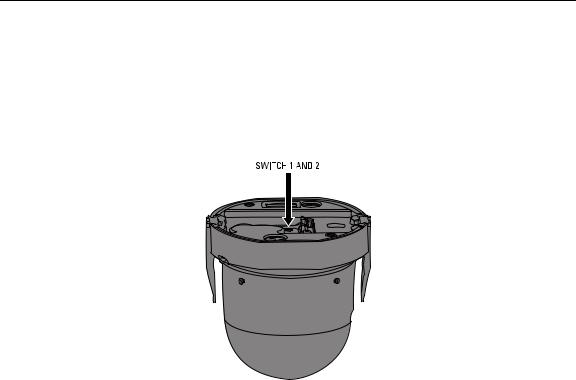
1.Perform one of the following options:
•View video using both analog and IP connections: Set the DIP switches on the top of the Spectra IV dome drive (refer to Figure 12). For DIP switch settings, refer to the labels located on the top of the dome drive, or refer to Switch Settings on page 3.
•View video using the IP connection: If your dome drive is part of a Spectra IV IP system, you do not need to set the DIP switches.
NOTE: When connecting more than one Spectra IV dome to a single controller, terminate the unit farthest from the controller. To terminate the dome drive set the SW2-10 switch to the ON position.
Figure 1. Setting the DIP Switches
2.Install the dome drive into the back box.
a.Align the blue and red tabs with the blue and red labels on the back box.
b.Push in the red tab and insert that side of the dome drive first.
c.Push in the blue tab and insert the dome drive into the back box the remainder of the way.
d.Continue pushing on the ends of the tabs until both sides click firmly into place.
2 |
C3462M (9/09) |

SWITCH SETTINGS
 WARNING: If you are using Pelco D-type or P-type control, your system may not operate if the baud rate and address switches are not set correctly. The switches are set at the factory at the defaults for Pelco D-type control (2400 baud and address 1).
Table A. Switch Settings for SW2
Special Systems |
|
|
|
|
|
|
|
|
|
|
|
|
|
|
|
|
|
|
|
|
|
Switch Number |
1 |
2 |
3 |
4 |
5 |
6 |
7 |
8 |
9 |
10 |
|
|
|
|
|
|
|
|
|
|
|
AD-32 Preset System |
ON |
|
|
|
|
|
|
|
|
|
|
|
|
|
|
|
|
|
|
|
|
CM9502 Setting |
|
ON |
|
|
|
|
|
|
|
|
|
|
|
|
|
|
|
|
|
|
|
Pelco Coaxitron Controller |
|
|
OFF |
|
|
|
|
|
|
|
|
|
|
|
|
|
|
|
|
|
|
Third-Party Coaxial Control |
|
|
ON |
|
|
|
|
|
|
|
|
|
|
|
|
|
|
|
|
|
|
Third-Party Pelco P-type Control |
|
|
ON |
|
|
|
|
|
|
|
|
|
|
|
|
|
|
|
|
|
|
|
|
|
|
|
|
|
|
|
|
|
Serial Port Settings |
|
|
|
|
|
|
|
|
|
|
|
|
|
|
|
|
|
|
|
|
|
Switch Number |
1 |
2 |
3 |
4 |
5 |
6 |
7 |
8 |
9 |
10 |
|
|
|
|
|
|
|
|
|
|
|
RS422 |
|
|
|
OFF |
OFF |
|
|
|
|
|
|
|
|
|
|
|
|
|
|
|
|
RS485, 4-Wire |
|
|
|
OFF |
ON |
|
|
|
|
|
|
|
|
|
|
|
|
|
|
|
|
RS485, 2-Wire |
|
|
|
ON |
ON |
|
|
|
|
|
|
|
|
|
|
|
|
|
|
|
|
|
|
|
|
|
|
|
|
|
|
|
Pelco D or P Protocol Baud Rate |
|
|
|
|
|
|
|
|
|
|
|
|
|
|
|
|
|
|
|
|
|
Switch Number |
1 |
2 |
3 |
4 |
5 |
6 |
7 |
8 |
9 |
10 |
|
|
|
|
|
|
|
|
|
|
|
2400 Baud (Default for D-type Control) |
|
|
|
|
|
OFF |
OFF |
OFF |
|
|
|
|
|
|
|
|
|
|
|
|
|
4800 Baud (Default for P-type Control) |
|
|
|
|
|
ON |
OFF |
OFF |
|
|
|
|
|
|
|
|
|
|
|
|
|
9600 Baud |
|
|
|
|
|
OFF |
ON |
OFF |
|
|
|
|
|
|
|
|
|
|
|
|
|
|
|
|
|
|
|
|
|
|
|
|
Video Cable Type |
|
|
|
|
|
|
|
|
|
|
|
|
|
|
|
|
|
|
|
|
|
Switch Number |
1 |
2 |
3 |
4 |
5 |
6 |
7 |
8 |
9 |
10 |
|
|
|
|
|
|
|
|
|
|
|
Coaxial Cable |
|
|
|
|
|
|
|
|
OFF |
|
|
|
|
|
|
|
|
|
|
|
|
UTP Cable |
|
|
|
|
|
|
|
|
ON |
|
|
|
|
|
|
|
|
|
|
|
|
|
|
|
|
|
|
|
|
|
|
|
Dome Termination |
|
|
|
|
|
|
|
|
|
|
|
|
|
|
|
|
|
|
|
|
|
Switch Number |
1 |
2 |
3 |
4 |
5 |
6 |
7 |
8 |
9 |
10 |
|
|
|
|
|
|
|
|
|
|
|
Terminated |
|
|
|
|
|
|
|
|
|
ON |
|
|
|
|
|
|
|
|
|
|
|
Not Terminated |
|
|
|
|
|
|
|
|
|
OFF |
|
|
|
|
|
|
|
|
|
|
|
C3462M (9/09) |
3 |
 Loading...