

Page 1
INSTALLATION
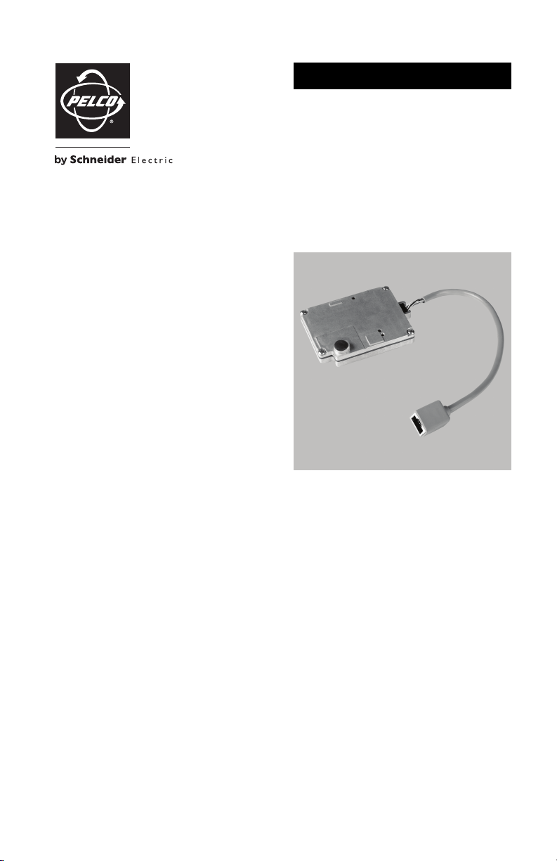
TXB-N Spectra® IV IP Communication Module
C3467M (4/10)
Page 2

Important Notices
LEGAL NOTICE
SOME PELCO EQUIPMENT CONTAINS, AND THE SOFTWARE ENABLES, AUDIO/VISUAL AND RECORDING
CAPABILITIES, THE IMPROPER USE OF WHICH MAY SUBJECT YOU TO CIVIL AND CRIMINAL PENALTIES.
APPLICABLE LAWS REGARDING THE USE OF SUCH CAPABILITIES VARY BETWEEN JURISDICTIONS AND
MAY REQUIRE, AMONG OTHER THINGS, EXPRESS WRITTEN CONSENT FROM RECORDED SUBJECTS. YOU
ARE SOLELY RESPONSIBLE FOR INSURING STRICT COMPLIANCE WITH SUCH LAWS AND FOR STRICT
ADHERENCE TO ANY/ALL RIGHTS OF PRIVACY AND PERSONALTY. USE OF THIS EQUIPMENT AND/OR
SOFTWARE FOR ILLEGAL SURVEILLANCE OR MONITORING SHALL BE DEEMED UNAUTHORIZED USE IN
VIOLATION OF THE END USER SOFTWARE AGREEMENT AND RESULT IN THE IMMEDIATE TERMINATION OF
YOUR LICENSE RIGHTS THEREUNDER.
REGULATORY NOTICES
This device complies with Part 15 of the FCC Rules. Operation is subject to the following two conditions:
(1) this device may not cause harmful interference, and (2) this device must accept any interference received,
including interference that may cause undesired operation.
RADIO AND TELEVISION INTERFERENCE
This equipment has been tested and found to comply with the limits of a Class B digital device, pursuant to
Part 15 of the FCC Rules. These limits are designed to provide reasonable protection against harmful
interference in a residential installation. This equipment generates, uses, and can radiate radio frequency
energy and, if not installed and used in accordance with the instructions, may cause harmful interference to
radio communications. However there is no guarantee that the interference will not occur in a particular
installation. If this equipment does cause harmful interference to radio or television reception, which can be
determined by turning the equipment off and on, the user is encouraged to try to correct the interference by
one or more of the following measures:
• Reorient or relocate the receiving antenna.
• Increase the separation between the equipment and the receiver.
• Connect the equipment into an outlet on a circuit different from that to which the receiver is connected.
• Consult the dealer or an experienced radio/TV technician for help.
You may also find helpful the following booklet, prepared by the FCC: “How to Identify and Resolve Radio-TV
Interference Problems.” This booklet is available from the U.S. Government Printing Office, Washington D.C.
20402.
Changes and modifications not expressly approved by the manufacturer or registrant of this equipment can
void your authority to operate this equipment under Federal Communications Commission’s rules.
This Class B digital apparatus complies with Canadian ICES-003.
Cet appareil numérique de la classe B est conforme à la norme NMB-003 du Canada.
OPEN SOURCE SOFTWARE NOTICE
This product includes certain open source or other software originated from third parties that is subject to the
GNU General Public License (GPL), GNU Library/Lesser General Public License (LGPL) and different and/or
additional copyright licenses, disclaimers and notices.
The exact terms of GPL, LGPL and some other licenses are provided to you with this product. Please refer to
the exact terms of the GPL and LGPL at www.fsf.org (Free Software Foundation) and www.opensource.org
(Open Source Initiative) regarding your rights under said license. You may obtain a complete corresponding
machine-readable copy of the source code of such software under the GPL or LGPL by sending your request to
[email protected] and the subject line should read Source Code Request. You will then receive a link
in the e-mail for you to download the source code.
This offer is valid for a period of three (3) years from the date of the distribution of this product by Pelco.
2 C3467M (4/10)
Page 3
Description
The TXB-N allows Spectra® IV and Spectra IV SE dome systems to transfer live video and data over an
Internet protocol (IP) network. The IP module provides H.264, MJPEG, and MPEG-4 compression for use
with most standard Web browsers. Once installed, the Spectra IV dome system retains all of the standard
Spectra features, while adding IP connectivity.
NOTE: The TXB-N module is only compatible with Spectra IV dome systems that use version 1.07 or
newer software. Dome systems with software older than version 1.07 do not have the capability to
operate over an IP network.
MODELS
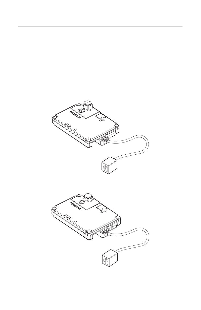
TXB-N-F Spectra IV IP communication module for in-ceiling back boxes
TXB-N-P Spectra IV IP communication module for pendant back boxes
Figure 1. TXB-N-F
Figure 2. TXB-N-P
C3467M (4/10) 3
Page 4
Installation
PARTS LIST
Qty Description
1 TXB-N module
2 MAC address label
1 Resource Disk
1 TXB-N Installation manual
1 Spectra IV IP Operation/Configuration manual
1 Device Utility Operation/Configuration manual
To access the back box PCB, use the following steps:
1. Turn off power to the dome system.
2. Remove the lower dome.
3. Remove the dome drive by pressing in the blue and red tabs on the sides of the dome drive. Gently
rock the dome drive to release the blue tab first, and then release the red tab.
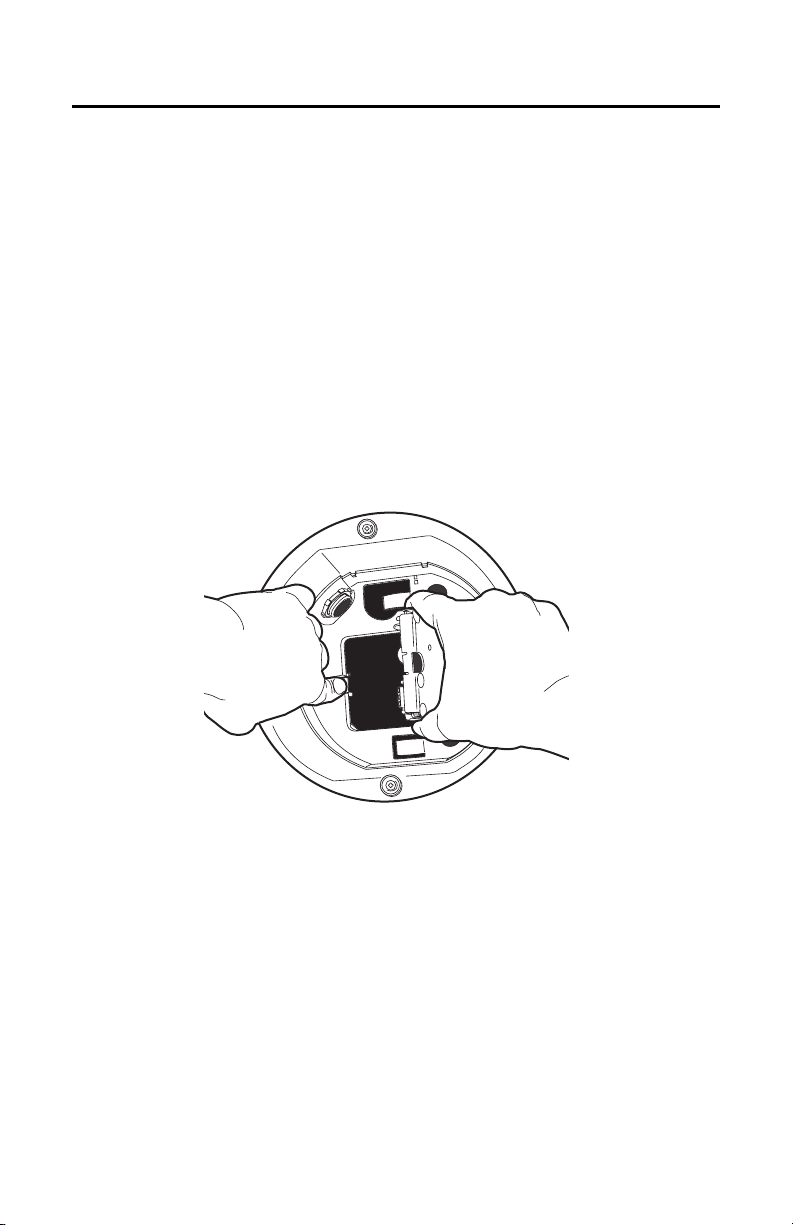
4. Open the hinged door to the box. Push the tab lock towards the back box wall of the unit and open
the door (refer to Figure 3).
Figure 3. Spectra IV Back Box Interconnect Door
4 C3467M (4/10)
Page 5
INSTALLING THE TXB-N
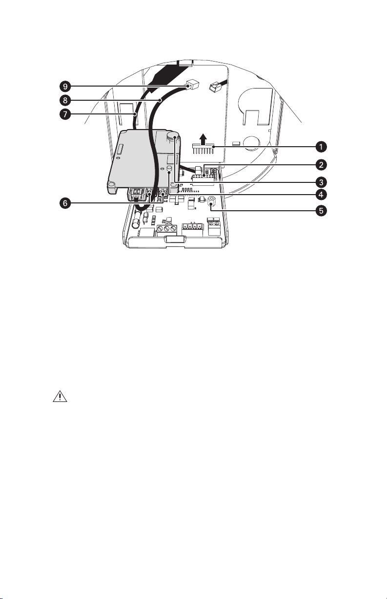
Figure 4. Installing the TXB-N
ì
Shorting Plug
î
16-Pin Connector
ï
Heat Sink Standoff
ñ
Captive Screw
ó
Standoff
To install the TXB-N into the back box, use the following steps (refer to Figure 4):
WARNING: The TXB-N-F is intended for use only with in-ceiling back boxes. The TXB-N-P is
intended for use only with pendant back boxes. If a TXB-N-F is installed in a pendant back box, the
unit will overheat and you will void the warranty. If a TXB-N-P is installed in an in-ceiling back box,
the unit will be damaged and you will void the warranty. Refer to Figure 1 and Figure 2 on page 3.
1. Ensure that you are installing the correct model TXB-N into the appropriate in-ceiling or pendant
model back box.
C3467M (4/10) 5
r
Audio Connectors
s
Video Coaxial Cable
t
Ethernet Cable
u
RJ-45 Connector
Page 6
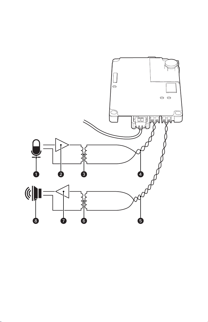
2. If you plan to use the audio functions, install your audio UTP cables into the audio line-in and
line-out connectors on the TXB-N.
NOTES:
• To take full advantage of the UTP distance and noise immunity benefits, you must use a
600-ohm impedance matching transformer (refer to Figure 5 on page 6).
• A stable power supply is required for optimal audio performance.
Figure 5. Audio Connections
ì
Microphone
î
Amplifier
ï
600-Ohm Impedance Matching Transformer
ñ
Line-In Audio UTP Cable
6 C3467M (4/10)
ó
Line-Out Audio UTP Cable
r
600-Ohm Impedance Matching Transformer
s
Amplifier
t
Speaker
Page 7
3. Remove the shorting plug from the 16-pin connector located on the back box circuit board.
4. Insert the TXB-N module into the 16-pin connector located on the back box circuit board. Secure the
module to the standoff on the circuit board using the captive screw on the TXB-N module.
5. Plug your network Ethernet cable into the RJ-45 connector to connect the Spectra IV dome system to
your existing network.
WARNING: An electrical short in the back box may occur if the metal BNC connector on the video
coaxial cable is not completely covered by the protective boot.
6. If you plan to view video using both analog and IP connections, connect the video coaxial cable from
the back box circuit board to the coaxial cable coming in from the outside. Make sure that the BNC
connector is completely covered by the protective boot.
If you plan to only view video using the IP connection, make sure that the BNC connector is completely
covered by the protective boot and is out of the way of the back box door.
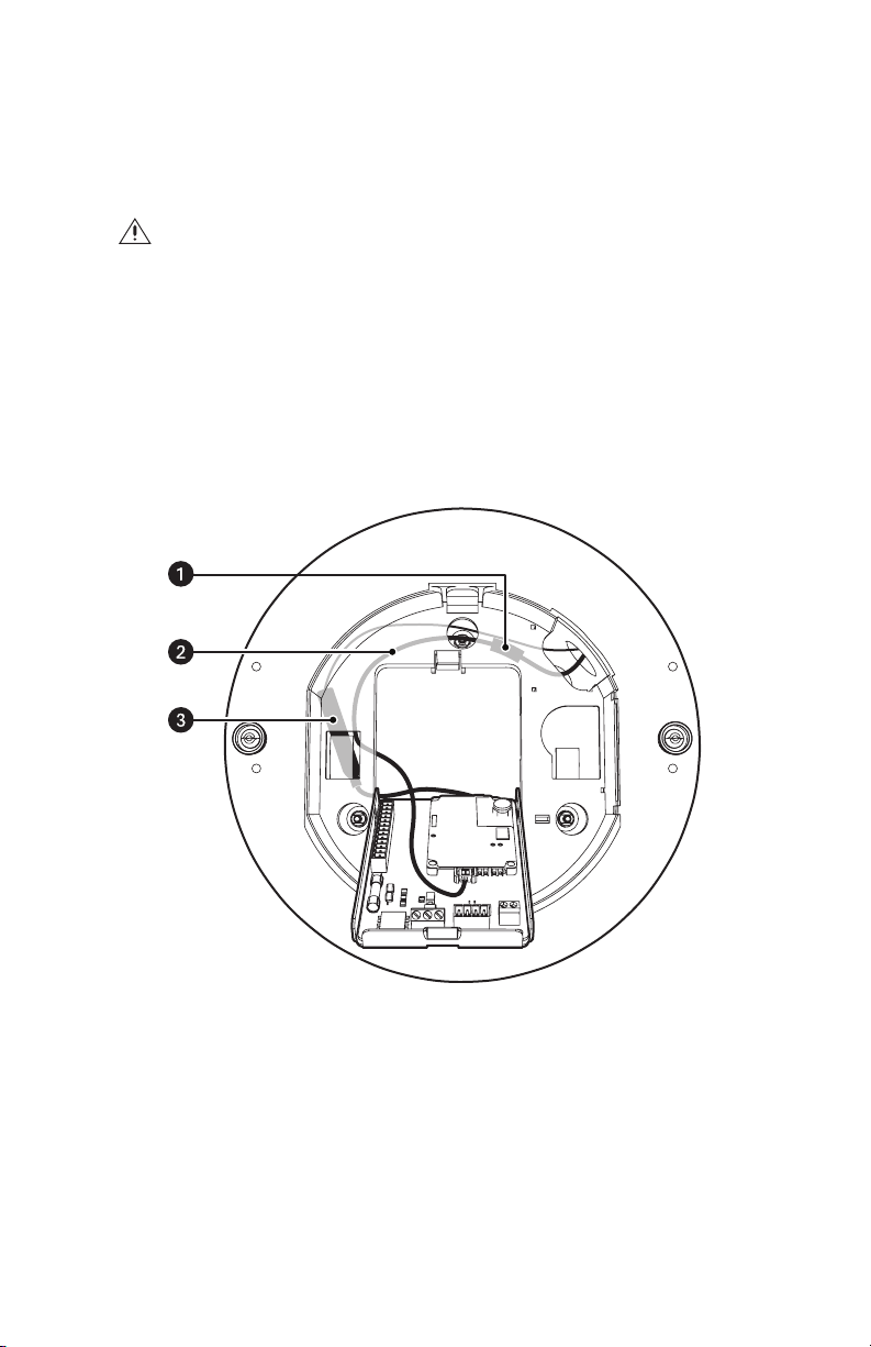
7. Before closing the interconnect door, ensure that no wires are between the top of the heat sink
standoff and the back box. Both the video coaxial cable and the Ethernet cable need to be routed
carefully to ensure clearance for the heat sink standoff. Refer to Figure 6.
8. Close the interconnect door. Snap the tab lock into place.
Figure 6. Routing the Cables
ì
RJ-45 Connector
î
Ethernet Cable
ï
Video Coaxial Cable
C3467M (4/10) 7
Page 8
INSTALLING THE DOME DRIVE
NOTE: For complete installation instructions, refer to the installation manual supplied with the Spectra IV
back box.
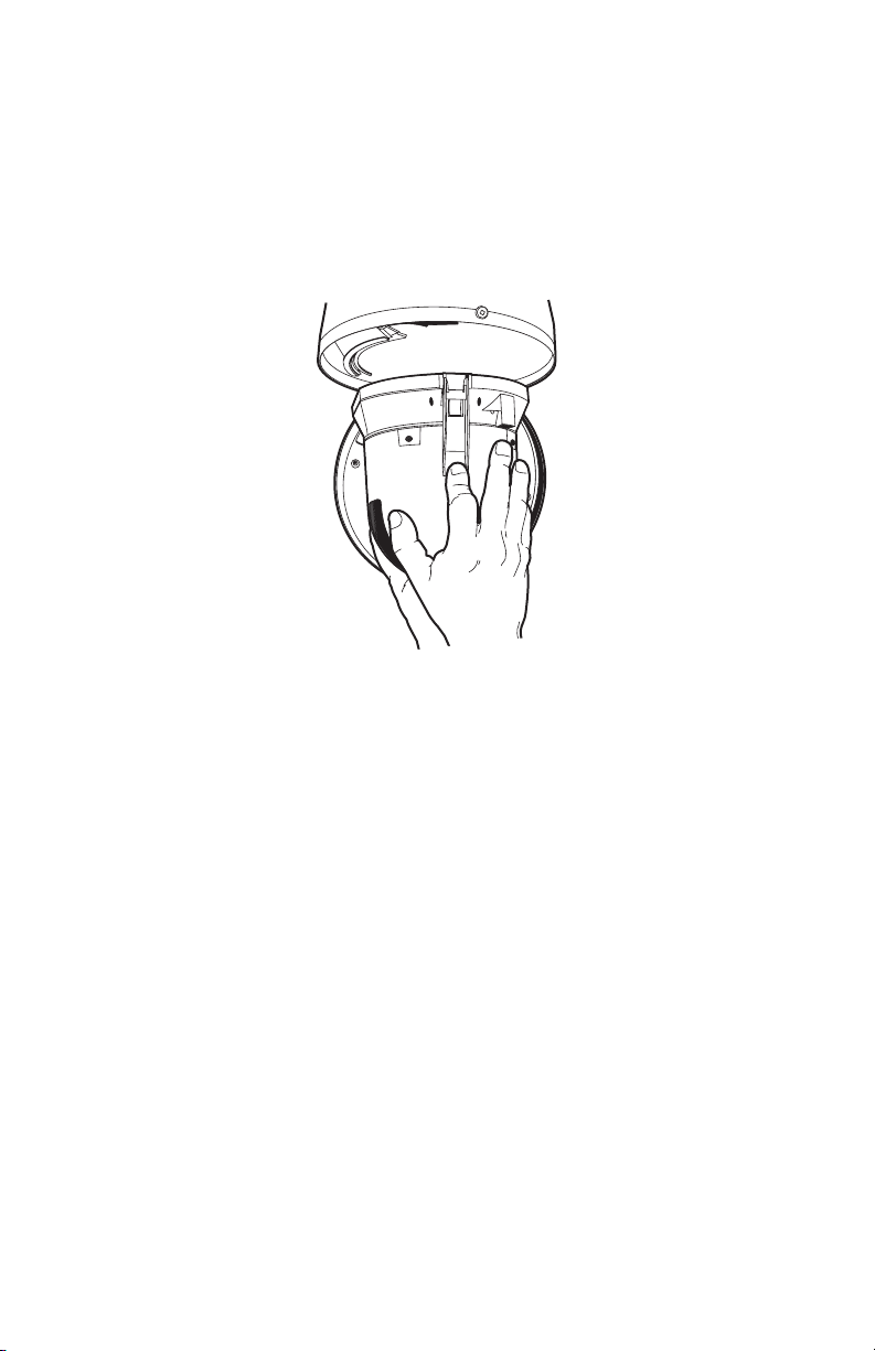
1. Install the dome drive (refer to Figure 7):
a. Line up the blue and red tabs with the blue and red labels. When pushing the tabs in, insert
the red tab first, and then the blue tab.
b. Continue pushing on the ends of the tabs until both tabs click into place.
Figure 7. Spectra IV Dome Drive Installation
2. Install the lower dome.
3. Apply power to the system.
8 C3467M (4/10)
Page 9

Troubleshooting
If the following instructions fail to solve your problem, contact Pelco Product Support at 1-800-289-9100
(USA and Canada) or +1-559-292-1981 (international) for assistance. Be sure to have the serial number
available when calling.
Do not try to repair the unit yourself. Leave maintenance and repairs to qualified technical personnel.
Symptom Possible Cause Suggested Solution
No video is displayed. Power is not connected. Check the power connector.
Video cable is not connected. Check the video connector.
TXB-N module is not inserted
properly.
Spectra IV information (model,
firmware, Pelco P and D
protocol addresses, and
communication settings) does
not appear after the
configuration cycle.
The unit does not respond to
commands.
The audio signal is weak. You are not using the correct
There is an echo when audio is
received.
The unit cannot complete its
configuration cycle.
Make sure your switches are
set to the proper settings.
type of transformer.
The wiring distance connecting
the audio equipment may be
too long.
The gain is not properly
adjusted.
The speaker volume is too high. Lower the speaker volume.
The microphone and the
speaker are too close together.
Your call station does not have
built-in echo cancellation.
Reinstall the TXB-N module.
Make sure the pins on the
module are inserted correctly.
Refer to Troubleshooting in the
Installation/Operation manual
shipped with the Spectra IV
dome drive.
Check all DIP switch settings on
the dome drive.
Be sure you are using a
600-ohm impedance matching
transformer
Test the equipment using a
shorter wiring distance.
If you are using an external
amplifier and it has an
adjustable gain, increase the
gain until the signal is
acceptable.
If your call station does not
have built-in echo cancellation,
move the microphone and
speaker farther apart.
Use a call station with built-in
echo cancellation.
C3467M (4/10) 9
Page 10

The materials used in the manufacture of this document and its components are compliant to the requirements of
Directive 2002/95/EC.
This equipment contains electrical or electronic components that must be recycled properly to comply with
Directive 2002/96/EC of the European Union regarding the disposal of waste electrical and electronic equipment
(WEEE). Contact your local dealer for procedures for recycling this equipment.
REVISION HISTORY
Manual # Date Comments
C3467M 3/10 Original version.
10 C3467M (4/10)
Page 11

PRODUCT WARRANTY AND RETURN INFORMATION
WARRANTY
Pelco will repair or replace, without charge, an y merchandise proved defective in material or workmanship for a period of one year after the date of
shipment.
Exceptions to this warranty are as noted below:
• Five years:
– Fiber optic products
– Unshielded Twisted Pair (UTP) transmission products
– CC370 1H-2, CC3701H-2X, CC3751H-2, CC3651H-2X, MC3651H-2, and MC3651H-2X camera models
• Three years:
– Pe lco-designed fixed network cameras and network dome cameras with Sarix™ technology.
– Pe lco-branded fixed camera models (CCC1390H Series, C10DN Series, C10CH Series, and IP3701H Series)
– EH150 0 Series enclosures
®
– Spectra
IV products (including Spectra IV IP)
– Cam closure
– DX Series digital video recorders (except DX9000 Se ries which is covered for a period of one year), DVR5100 Series digital video recorders,
– En dura
– Ge nex® Series products (multiplexers, server, and keyboard)
– PMCL200/300/400 Series LCD monitors
– PMCL5xx Series FHD monitors
• Two years:
– S tandard varifocal, fixed focal, and motorized zoom lenses.
– DF5/DF8 Series fixed dom e products
– Lega cy® Series integrated positioning systems
– Spectra III™, Spectra Mini, Spectra Mini IP, Esprit®, ExSite®, and PS20 scanners, including when u sed in continuous motion applications.
– Espr it Ti and TI2500 Series thermal imaging products
– Espr it and WW5700 Series window wiper (excluding wiper blades).
– CM 6700/CM6800/CM9700 Series matrix
– Di gital Light Processing (DLP®) displays (except lamp and color wheel). The lamp and color wheel will be covered for a period of 90 days.
– Inte lli-M
•One year:
– Video cassette record ers (VCRs), except video heads. Video heads will be covered for a period of six months.
• Six months:
– Al l pan and tilts, scanners, or preset lenses used in continuous motion applicatio ns (preset scan, tour, and auto scan modes).
Pelco will warrant all replacement parts and repairs for 90 days from the date of Pelco shipment. All goods requiring warranty repair shall be sent
freight prepaid to a Pelco designated locatio n. Repairs made necessary by reason of misuse, alteration, normal wear, or accident are no t covered under
this warranty.
Pelco assumes no risk and shall be subject to no liability for damages or loss resul ting from the specific use or application made of the Products. Pelco’s
liability for any claim, whether based on breach of contract, negligence, infringement of any rights of any party or product liability, relating to the Products
shall not exceed the price paid by the Dealer to Pelco for such Products. In no event will Pelco be liable for any special, incidental, or consequential
damages (including loss of use, loss of prof it, and claims of third parties) however caused, whether by the negligence of Pelco or otherwise.
The above warranty provides the Dealer with spe cific legal rights. The Dealer may also have additional right s, which are subject to variation from state
to state.
If a warranty repair is required, the Dealer must contact Pelco at (800) 289-9100 or (559) 292-1981 to obtain a Repair Authorization number (RA), and
provide the following information:
1. Model and serial number
2. Date of shipment, P.O. number, sales order number, or Pelco invoice number
3. Details of the defect or problem
If there is a dispute regarding the warranty of a product that does not fall un der the warranty conditions stated above, please include a written
explanation with the product wh en returned.
Method of return shipment shall be the same or equal to the method by which the item was received by Pelco.
RETURNS
To expedite parts returned for repair or credit, please call Pelco at (800) 289-9100 or (559) 292-1981 to obtain an authorization number (CA number if
returned for credit, and RA number if returned for repair) and designated return location.
All merchandise returned for credit may be subject to a 20 percent restocking and refurbishing charge.
Goods returned for repair or credit should be clearly identified with the assigned CA or RA number and freight should be prepaid.
®
Series (IS, ICS, IP) integrated camera systems
®
Digital Sentry
The air filter is not covered under warranty.
Series hardware products, DVX Series digital video recorders, and NVR300 Series network video recorders
®
Series distributed network-based video pro ducts
®
eIDC controllers
2-10-10
Pelco, the Pelco logo, Camclosure, Digital Sentry, Endura, Esprit, ExSite, Genex, Intelli-M, Legacy, and Spectra are registered trademarks of Pelco, Inc.
Spectra III is a trademark of Pelco, Inc.
DLP is a registered trademark of Texas Instruments Incorporated.
All product names and services identified t hroughout this document are trademarks or registered trademarks of their re spective companies.
The absence of a trademark or registered trademark from this document does not constitute a waiver of intellectual property rights.
© Copyright 2010, Pelco, Inc. All rights reserved.
Page 12

www.pelco.com
Pelco, Inc. Worldwide Headquarters 3500 Pelco Way Clovis, California 93612 USA
USA & Canada Tel (800) 289-9100 Fax (800) 289-9150
International Tel +1 (559) 292-1981 Fax +1 (559) 348-1120
 Loading...