


 Loading...
I N S T A L L A T I O N / O P E R A T I O N
System 9760®
Video Matrix Switching
Control System
C1572M (9/05)

Contents
Important Safety Instructions . . . . . . . . . . . . . . . . . . . . . . . . . . . . . . . . . . . . . . . . . . . . . . . . . . . . . . . . . . . . . . . . . . . . . . . . . . . . . . . . . . . . . . . . . . . .7
Regulatory Notices . . . . . . . . . . . . . . . . . . . . . . . . . . . . . . . . . . . . . . . . . . . . . . . . . . . . . . . . . . . . . . . . . . . . . . . . . . . . . . . . . . . . . . . . . . . . . . . . . . . .8
System Overview . . . . . . . . . . . . . . . . . . . . . . . . . . . . . . . . . . . . . . . . . . . . . . . . . . . . . . . . . . . . . . . . . . . . . . . . . . . . . . . . . . . . . . . . . . . . . . . . . . . . |
.9 |
Description . . . . . . . . . . . . . . . . . . . . . . . . . . . . . . . . . . . . . . . . . . . . . . . . . . . . . . . . . . . . . . . . . . . . . . . . . . . . . . . . . . . . . . . . . . . . . . . . . . . . . |
.9 |
Models . . . . . . . . . . . . . . . . . . . . . . . . . . . . . . . . . . . . . . . . . . . . . . . . . . . . . . . . . . . . . . . . . . . . . . . . . . . . . . . . . . . . . . . . . . . . . . . . . . . . . . . . |
10 |
CPU Controller and Components . . . . . . . . . . . . . . . . . . . . . . . . . . . . . . . . . . . . . . . . . . . . . . . . . . . . . . . . . . . . . . . . . . . . . . . . . . . . . . . |
10 |
Matrix Bay and Components . . . . . . . . . . . . . . . . . . . . . . . . . . . . . . . . . . . . . . . . . . . . . . . . . . . . . . . . . . . . . . . . . . . . . . . . . . . . . . . . . . |
10 |
Keyboards . . . . . . . . . . . . . . . . . . . . . . . . . . . . . . . . . . . . . . . . . . . . . . . . . . . . . . . . . . . . . . . . . . . . . . . . . . . . . . . . . . . . . . . . . . . . . . . . . |
10 |
Network Interface Unit . . . . . . . . . . . . . . . . . . . . . . . . . . . . . . . . . . . . . . . . . . . . . . . . . . . . . . . . . . . . . . . . . . . . . . . . . . . . . . . . . . . . . . . |
11 |
Optional Components . . . . . . . . . . . . . . . . . . . . . . . . . . . . . . . . . . . . . . . . . . . . . . . . . . . . . . . . . . . . . . . . . . . . . . . . . . . . . . . . . . . . . . . . |
11 |
Compatible Receivers . . . . . . . . . . . . . . . . . . . . . . . . . . . . . . . . . . . . . . . . . . . . . . . . . . . . . . . . . . . . . . . . . . . . . . . . . . . . . . . . . . . . . . . . |
11 |
System Setup . . . . . . . . . . . . . . . . . . . . . . . . . . . . . . . . . . . . . . . . . . . . . . . . . . . . . . . . . . . . . . . . . . . . . . . . . . . . . . . . . . . . . . . . . . . . . . . . . . . . . . .12 System Setup Overview . . . . . . . . . . . . . . . . . . . . . . . . . . . . . . . . . . . . . . . . . . . . . . . . . . . . . . . . . . . . . . . . . . . . . . . . . . . . . . . . . . . . . . . . . . .12 Unpacking . . . . . . . . . . . . . . . . . . . . . . . . . . . . . . . . . . . . . . . . . . . . . . . . . . . . . . . . . . . . . . . . . . . . . . . . . . . . . . . . . . . . . . . . . . . . . . . . . . . . .13 Unpacking the CM9700-CC1 . . . . . . . . . . . . . . . . . . . . . . . . . . . . . . . . . . . . . . . . . . . . . . . . . . . . . . . . . . . . . . . . . . . . . . . . . . . . . . . . . . .13 Unpacking the CM9760-MXB . . . . . . . . . . . . . . . . . . . . . . . . . . . . . . . . . . . . . . . . . . . . . . . . . . . . . . . . . . . . . . . . . . . . . . . . . . . . . . . . . .13 Installing the CM9700-CC1 Controller . . . . . . . . . . . . . . . . . . . . . . . . . . . . . . . . . . . . . . . . . . . . . . . . . . . . . . . . . . . . . . . . . . . . . . . . . . . . . . . .14 Selecting a Location for the CM9700-CC1 . . . . . . . . . . . . . . . . . . . . . . . . . . . . . . . . . . . . . . . . . . . . . . . . . . . . . . . . . . . . . . . . . . . . . . . .14 Mounting the CM9700-CC1 . . . . . . . . . . . . . . . . . . . . . . . . . . . . . . . . . . . . . . . . . . . . . . . . . . . . . . . . . . . . . . . . . . . . . . . . . . . . . . . . . . .14 Connecting the CM9700-CC1 . . . . . . . . . . . . . . . . . . . . . . . . . . . . . . . . . . . . . . . . . . . . . . . . . . . . . . . . . . . . . . . . . . . . . . . . . . . . . . . . . .16 Powering On the CM9700-CC1 . . . . . . . . . . . . . . . . . . . . . . . . . . . . . . . . . . . . . . . . . . . . . . . . . . . . . . . . . . . . . . . . . . . . . . . . . . . . . . . . .21 Installing CM9760-MXB Matrix Bay(s) . . . . . . . . . . . . . . . . . . . . . . . . . . . . . . . . . . . . . . . . . . . . . . . . . . . . . . . . . . . . . . . . . . . . . . . . . . . . . . .21 Selecting a Location for the CM9760-MXB . . . . . . . . . . . . . . . . . . . . . . . . . . . . . . . . . . . . . . . . . . . . . . . . . . . . . . . . . . . . . . . . . . . . . . .21 Mounting the CM9760-MXB . . . . . . . . . . . . . . . . . . . . . . . . . . . . . . . . . . . . . . . . . . . . . . . . . . . . . . . . . . . . . . . . . . . . . . . . . . . . . . . . . .22 Verifying CM9760-MXB Component Installation . . . . . . . . . . . . . . . . . . . . . . . . . . . . . . . . . . . . . . . . . . . . . . . . . . . . . . . . . . . . . . . . . . .23 Connecting the CM9760-MXB to the CM9700-CC1 . . . . . . . . . . . . . . . . . . . . . . . . . . . . . . . . . . . . . . . . . . . . . . . . . . . . . . . . . . . . . . . . .25 Connecting Power to the CM9760-MXB . . . . . . . . . . . . . . . . . . . . . . . . . . . . . . . . . . . . . . . . . . . . . . . . . . . . . . . . . . . . . . . . . . . . . . . . .26 Powering On the CM9760-MXB . . . . . . . . . . . . . . . . . . . . . . . . . . . . . . . . . . . . . . . . . . . . . . . . . . . . . . . . . . . . . . . . . . . . . . . . . . . . . . . .26 Checking Diagnostic LEDs . . . . . . . . . . . . . . . . . . . . . . . . . . . . . . . . . . . . . . . . . . . . . . . . . . . . . . . . . . . . . . . . . . . . . . . . . . . . . . . . . . . .26 Connecting Video Inputs and Video Outputs . . . . . . . . . . . . . . . . . . . . . . . . . . . . . . . . . . . . . . . . . . . . . . . . . . . . . . . . . . . . . . . . . . . . . .29 Verifying System Operation . . . . . . . . . . . . . . . . . . . . . . . . . . . . . . . . . . . . . . . . . . . . . . . . . . . . . . . . . . . . . . . . . . . . . . . . . . . . . . . . . . . . . . . .30
CM9700-CC1 Component Installation or Replacement . . . . . . . . . . . . . . . . . . . . . . . . . . . . . . . . . . . . . . . . . . . . . . . . . . . . . . . . . . . . . . . . . . . . . . .31 Removing the CM9700-CC1 Top Cover . . . . . . . . . . . . . . . . . . . . . . . . . . . . . . . . . . . . . . . . . . . . . . . . . . . . . . . . . . . . . . . . . . . . . . . . . . . . . . .31 Installing or Replacing a CM9700-SER Card . . . . . . . . . . . . . . . . . . . . . . . . . . . . . . . . . . . . . . . . . . . . . . . . . . . . . . . . . . . . . . . . . . . . . . . . . . .32
CM9760-MXB Component Installation or Replacement . . . . . . . . . . . . . . . . . . . . . . . . . . . . . . . . . . . . . . . . . . . . . . . . . . . . . . . . . . . . . . . . . . . . . . |
34 |
Installing or Replacing Rear Panel Cards . . . . . . . . . . . . . . . . . . . . . . . . . . . . . . . . . . . . . . . . . . . . . . . . . . . . . . . . . . . . . . . . . . . . . . . . . . . . . |
34 |
Installing or Replacing a CM9760-RPC Rear Panel Input Card . . . . . . . . . . . . . . . . . . . . . . . . . . . . . . . . . . . . . . . . . . . . . . . . . . . . . . . . |
34 |
Installing or Replacing a CM9760-RPL Rear Panel Looping Card . . . . . . . . . . . . . . . . . . . . . . . . . . . . . . . . . . . . . . . . . . . . . . . . . . . . . . |
37 |
Installing or Replacing a CM9760-DFC Downframe Card . . . . . . . . . . . . . . . . . . . . . . . . . . . . . . . . . . . . . . . . . . . . . . . . . . . . . . . . . . . . |
39 |
Installing or Replacing a CM9760-DFL Downframe Looping Card . . . . . . . . . . . . . . . . . . . . . . . . . . . . . . . . . . . . . . . . . . . . . . . . . . . . . . |
41 |
Installing or Replacing a CM9760-RPM Rear Panel Output Card . . . . . . . . . . . . . . . . . . . . . . . . . . . . . . . . . . . . . . . . . . . . . . . . . . . . . . |
43 |
Installing or Replacing a CM9760-VCC Video Input Card . . . . . . . . . . . . . . . . . . . . . . . . . . . . . . . . . . . . . . . . . . . . . . . . . . . . . . . . . . . . . . . . . |
45 |
Installing a CM9760-VCC Card . . . . . . . . . . . . . . . . . . . . . . . . . . . . . . . . . . . . . . . . . . . . . . . . . . . . . . . . . . . . . . . . . . . . . . . . . . . . . . . . . |
45 |
Replacing a CM9760-VCC Card . . . . . . . . . . . . . . . . . . . . . . . . . . . . . . . . . . . . . . . . . . . . . . . . . . . . . . . . . . . . . . . . . . . . . . . . . . . . . . . . |
47 |
Installing or Replacing a CM9760-VMC Video Output Card . . . . . . . . . . . . . . . . . . . . . . . . . . . . . . . . . . . . . . . . . . . . . . . . . . . . . . . . . . . . . . . |
48 |
Installing a CM9760-VMC Card . . . . . . . . . . . . . . . . . . . . . . . . . . . . . . . . . . . . . . . . . . . . . . . . . . . . . . . . . . . . . . . . . . . . . . . . . . . . . . . . |
48 |
Replacing a CM9760-VMC Card . . . . . . . . . . . . . . . . . . . . . . . . . . . . . . . . . . . . . . . . . . . . . . . . . . . . . . . . . . . . . . . . . . . . . . . . . . . . . . . . |
52 |
Installing a CM9760-VMM Video Output Module . . . . . . . . . . . . . . . . . . . . . . . . . . . . . . . . . . . . . . . . . . . . . . . . . . . . . . . . . . . . . . . . . . . . . . |
52 |
Installing or Replacing a Power Supply . . . . . . . . . . . . . . . . . . . . . . . . . . . . . . . . . . . . . . . . . . . . . . . . . . . . . . . . . . . . . . . . . . . . . . . . . . . . . . . |
53 |
Installing a Backup Power Supply . . . . . . . . . . . . . . . . . . . . . . . . . . . . . . . . . . . . . . . . . . . . . . . . . . . . . . . . . . . . . . . . . . . . . . . . . . . . . . |
53 |
Replacing a Power Supply . . . . . . . . . . . . . . . . . . . . . . . . . . . . . . . . . . . . . . . . . . . . . . . . . . . . . . . . . . . . . . . . . . . . . . . . . . . . . . . . . . . . |
54 |
Replacing a Power Supply Fuse . . . . . . . . . . . . . . . . . . . . . . . . . . . . . . . . . . . . . . . . . . . . . . . . . . . . . . . . . . . . . . . . . . . . . . . . . . . . . . . . . . . . . |
55 |
Enabling/Disabling the Power Supply Alarm . . . . . . . . . . . . . . . . . . . . . . . . . . . . . . . . . . . . . . . . . . . . . . . . . . . . . . . . . . . . . . . . . . . . . . . . . . |
56 |
System Programming Using DOS . . . . . . . . . . . . . . . . . . . . . . . . . . . . . . . . . . . . . . . . . . . . . . . . . . . . . . . . . . . . . . . . . . . . . . . . . . . . . . . . . . . . . . . . |
57 |
Performing System 9760 DOS Programming Tasks . . . . . . . . . . . . . . . . . . . . . . . . . . . . . . . . . . . . . . . . . . . . . . . . . . . . . . . . . . . . . . . . . . . . . . |
57 |
Copying Configuration Files from the CM9700-MGR to the CM9700-CC1 . . . . . . . . . . . . . . . . . . . . . . . . . . . . . . . . . . . . . . . . . . . . . . . |
57 |
C1572M (9/05) |
3 |
Setting and Adjusting System Time in a Single-Node System . . . . . . . . . . . . . . . . . . . . . . . . . . . . . . . . . . . . . . . . . . . . . . . . . . . . . . . .58 Setting and Adjusting System Time in a Multi-Node System . . . . . . . . . . . . . . . . . . . . . . . . . . . . . . . . . . . . . . . . . . . . . . . . . . . . . . . . .62 DOS Filename Conventions . . . . . . . . . . . . . . . . . . . . . . . . . . . . . . . . . . . . . . . . . . . . . . . . . . . . . . . . . . . . . . . . . . . . . . . . . . . . . . . . . . . . . . . .67 DOS Command Reference . . . . . . . . . . . . . . . . . . . . . . . . . . . . . . . . . . . . . . . . . . . . . . . . . . . . . . . . . . . . . . . . . . . . . . . . . . . . . . . . . . . . . . . . .67
System Diagnostics . . . . . . . . . . . . . . . . . . . . . . . . . . . . . . . . . . . . . . . . . . . . . . . . . . . . . . . . . . . . . . . . . . . . . . . . . . . . . . . . . . . . . . . . . . . . . . . . . .72 Monitoring CM9700-CC1 Functions . . . . . . . . . . . . . . . . . . . . . . . . . . . . . . . . . . . . . . . . . . . . . . . . . . . . . . . . . . . . . . . . . . . . . . . . . . . . . . . . .72 Viewing Monitor Box Diagnostics . . . . . . . . . . . . . . . . . . . . . . . . . . . . . . . . . . . . . . . . . . . . . . . . . . . . . . . . . . . . . . . . . . . . . . . . . . . . . .73 Allocating Monitors to Monitor Boxes . . . . . . . . . . . . . . . . . . . . . . . . . . . . . . . . . . . . . . . . . . . . . . . . . . . . . . . . . . . . . . . . . . . . . . . . . . .74 Entering CM9700-CC1 PC Keyboard Commands . . . . . . . . . . . . . . . . . . . . . . . . . . . . . . . . . . . . . . . . . . . . . . . . . . . . . . . . . . . . . . . . . . .75 Viewing Multi-Node System Status . . . . . . . . . . . . . . . . . . . . . . . . . . . . . . . . . . . . . . . . . . . . . . . . . . . . . . . . . . . . . . . . . . . . . . . . . . . . . . . . .77 Entering CM9700-NW1 PC Keyboard Commands . . . . . . . . . . . . . . . . . . . . . . . . . . . . . . . . . . . . . . . . . . . . . . . . . . . . . . . . . . . . . . . . . .78
Troubleshooting . . . . . . . . . . . . . . . . . . . . . . . . . . . . . . . . . . . . . . . . . . . . . . . . . . . . . . . . . . . . . . . . . . . . . . . . . . . . . . . . . . . . . . . . . . . . . . . . . . . . .79
General Troubleshooting Guidelines . . . . . . . . . . . . . . . . . . . . . . . . . . . . . . . . . . . . . . . . . . . . . . . . . . . . . . . . . . . . . . . . . . . . . . . . . . . . . . . . .79
Troubleshooting the CM9700-CC1 . . . . . . . . . . . . . . . . . . . . . . . . . . . . . . . . . . . . . . . . . . . . . . . . . . . . . . . . . . . . . . . . . . . . . . . . . . . . . . . . . .79
Troubleshooting the CM9760-MXB . . . . . . . . . . . . . . . . . . . . . . . . . . . . . . . . . . . . . . . . . . . . . . . . . . . . . . . . . . . . . . . . . . . . . . . . . . . . . . . . . .81
CM9700-CC1 Controller . . . . . . . . . . . . . . . . . . . . . . . . . . . . . . . . . . . . . . . . . . . . . . . . . . . . . . . . . . . . . . . . . . . . . . . . . . . . . . . . . . . . . . . . . . . . . . .82
Description . . . . . . . . . . . . . . . . . . . . . . . . . . . . . . . . . . . . . . . . . . . . . . . . . . . . . . . . . . . . . . . . . . . . . . . . . . . . . . . . . . . . . . . . . . . . . . . . . . . . .82
Front View . . . . . . . . . . . . . . . . . . . . . . . . . . . . . . . . . . . . . . . . . . . . . . . . . . . . . . . . . . . . . . . . . . . . . . . . . . . . . . . . . . . . . . . . . . . . . . . . . . . . .83
Rear View . . . . . . . . . . . . . . . . . . . . . . . . . . . . . . . . . . . . . . . . . . . . . . . . . . . . . . . . . . . . . . . . . . . . . . . . . . . . . . . . . . . . . . . . . . . . . . . . . . . . . .84
Directory Structure . . . . . . . . . . . . . . . . . . . . . . . . . . . . . . . . . . . . . . . . . . . . . . . . . . . . . . . . . . . . . . . . . . . . . . . . . . . . . . . . . . . . . . . . . . . . . . .86
9700 Directory . . . . . . . . . . . . . . . . . . . . . . . . . . . . . . . . . . . . . . . . . . . . . . . . . . . . . . . . . . . . . . . . . . . . . . . . . . . . . . . . . . . . . . . . . . . . . .87
TESTPORT Directory . . . . . . . . . . . . . . . . . . . . . . . . . . . . . . . . . . . . . . . . . . . . . . . . . . . . . . . . . . . . . . . . . . . . . . . . . . . . . . . . . . . . . . . . .88
DOS Directory . . . . . . . . . . . . . . . . . . . . . . . . . . . . . . . . . . . . . . . . . . . . . . . . . . . . . . . . . . . . . . . . . . . . . . . . . . . . . . . . . . . . . . . . . . . . . .88
CM9760-MXB Matrix Bay . . . . . . . . . . . . . . . . . . . . . . . . . . . . . . . . . . . . . . . . . . . . . . . . . . . . . . . . . . . . . . . . . . . . . . . . . . . . . . . . . . . . . . . . . . . . . .89 Description . . . . . . . . . . . . . . . . . . . . . . . . . . . . . . . . . . . . . . . . . . . . . . . . . . . . . . . . . . . . . . . . . . . . . . . . . . . . . . . . . . . . . . . . . . . . . . . . . . . . .89 Functional System Overview . . . . . . . . . . . . . . . . . . . . . . . . . . . . . . . . . . . . . . . . . . . . . . . . . . . . . . . . . . . . . . . . . . . . . . . . . . . . . . . . . .89 Front View . . . . . . . . . . . . . . . . . . . . . . . . . . . . . . . . . . . . . . . . . . . . . . . . . . . . . . . . . . . . . . . . . . . . . . . . . . . . . . . . . . . . . . . . . . . . . . . . . . . . .91 Rear View . . . . . . . . . . . . . . . . . . . . . . . . . . . . . . . . . . . . . . . . . . . . . . . . . . . . . . . . . . . . . . . . . . . . . . . . . . . . . . . . . . . . . . . . . . . . . . . . . . . . . .91 Video Input and Output Cards . . . . . . . . . . . . . . . . . . . . . . . . . . . . . . . . . . . . . . . . . . . . . . . . . . . . . . . . . . . . . . . . . . . . . . . . . . . . . . . . . . . . . .93 CM9760-VCC Video Input Card . . . . . . . . . . . . . . . . . . . . . . . . . . . . . . . . . . . . . . . . . . . . . . . . . . . . . . . . . . . . . . . . . . . . . . . . . . . . . . . . .93 CM9760-VMC Video Output Card . . . . . . . . . . . . . . . . . . . . . . . . . . . . . . . . . . . . . . . . . . . . . . . . . . . . . . . . . . . . . . . . . . . . . . . . . . . . . . .94 Rear Panel Cards . . . . . . . . . . . . . . . . . . . . . . . . . . . . . . . . . . . . . . . . . . . . . . . . . . . . . . . . . . . . . . . . . . . . . . . . . . . . . . . . . . . . . . . . . . . . . . . .95 CM9760-RPC Rear Panel Input Card . . . . . . . . . . . . . . . . . . . . . . . . . . . . . . . . . . . . . . . . . . . . . . . . . . . . . . . . . . . . . . . . . . . . . . . . . . . . .95 CM9760-RPL Rear Panel Looping Card . . . . . . . . . . . . . . . . . . . . . . . . . . . . . . . . . . . . . . . . . . . . . . . . . . . . . . . . . . . . . . . . . . . . . . . . . . .96 CM9760-RPM Rear Panel Output Card . . . . . . . . . . . . . . . . . . . . . . . . . . . . . . . . . . . . . . . . . . . . . . . . . . . . . . . . . . . . . . . . . . . . . . . . . . .98 CM9760-DFC Rear Panel Downframe Card . . . . . . . . . . . . . . . . . . . . . . . . . . . . . . . . . . . . . . . . . . . . . . . . . . . . . . . . . . . . . . . . . . . . . . .99 CM9760-DFL Rear Panel Downframe Looping Card . . . . . . . . . . . . . . . . . . . . . . . . . . . . . . . . . . . . . . . . . . . . . . . . . . . . . . . . . . . . . . . .100 Power Supplies . . . . . . . . . . . . . . . . . . . . . . . . . . . . . . . . . . . . . . . . . . . . . . . . . . . . . . . . . . . . . . . . . . . . . . . . . . . . . . . . . . . . . . . . . . . . . . . .101 Sideframing and Downframing . . . . . . . . . . . . . . . . . . . . . . . . . . . . . . . . . . . . . . . . . . . . . . . . . . . . . . . . . . . . . . . . . . . . . . . . . . . . . . . . . . . .102 Sideframing . . . . . . . . . . . . . . . . . . . . . . . . . . . . . . . . . . . . . . . . . . . . . . . . . . . . . . . . . . . . . . . . . . . . . . . . . . . . . . . . . . . . . . . . . . . . . . .103 Downframing . . . . . . . . . . . . . . . . . . . . . . . . . . . . . . . . . . . . . . . . . . . . . . . . . . . . . . . . . . . . . . . . . . . . . . . . . . . . . . . . . . . . . . . . . . . . .105 Using a Combination of Sideframing and Downframing . . . . . . . . . . . . . . . . . . . . . . . . . . . . . . . . . . . . . . . . . . . . . . . . . . . . . . . . . . . .107 Downframing to the CM9760-MXBL . . . . . . . . . . . . . . . . . . . . . . . . . . . . . . . . . . . . . . . . . . . . . . . . . . . . . . . . . . . . . . . . . . . . . . . . . . .108
Specifications . . . . . . . . . . . . . . . . . . . . . . . . . . . . . . . . . . . . . . . . . . . . . . . . . . . . . . . . . . . . . . . . . . . . . . . . . . . . . . . . . . . . . . . . . . . . . . . . . . . . . .109
CM9700-CC1 Specifications . . . . . . . . . . . . . . . . . . . . . . . . . . . . . . . . . . . . . . . . . . . . . . . . . . . . . . . . . . . . . . . . . . . . . . . . . . . . . . . . . . . . . .109
CM9760-MXB Specifications . . . . . . . . . . . . . . . . . . . . . . . . . . . . . . . . . . . . . . . . . . . . . . . . . . . . . . . . . . . . . . . . . . . . . . . . . . . . . . . . . . . . .109
Appendix A. CM9700-CC1 ASCII Protocol Communication . . . . . . . . . . . . . . . . . . . . . . . . . . . . . . . . . . . . . . . . . . . . . . . . . . . . . . . . . . . . . . . . . . . |
110 |
ACD to CM9700-CC1 Connections . . . . . . . . . . . . . . . . . . . . . . . . . . . . . . . . . . . . . . . . . . . . . . . . . . . . . . . . . . . . . . . . . . . . . . . . . . . . . . . . . |
110 |
Connecting an ACD DB9 Port to a CM9700-CC1 DB9 Port . . . . . . . . . . . . . . . . . . . . . . . . . . . . . . . . . . . . . . . . . . . . . . . . . . . . . . . . . . |
110 |
Connecting an ACD DB9 Port to a CM9700-CC1 RJ-45 Port . . . . . . . . . . . . . . . . . . . . . . . . . . . . . . . . . . . . . . . . . . . . . . . . . . . . . . . . . |
111 |
ASCII Protocol Commands Supported by the CM9700-CC1 . . . . . . . . . . . . . . . . . . . . . . . . . . . . . . . . . . . . . . . . . . . . . . . . . . . . . . . . . . . . . . |
112 |
Appendix B. CM9760-MXB Sideframe and Downframe Configuration Examples . . . . . . . . . . . . . . . . . . . . . . . . . . . . . . . . . . . . . . . . . . . . . . . . . .121
Sideframe-Only Configuration Examples . . . . . . . . . . . . . . . . . . . . . . . . . . . . . . . . . . . . . . . . . . . . . . . . . . . . . . . . . . . . . . . . . . . . . . . . . . . . .122
Downframe-Only Configuration Examples . . . . . . . . . . . . . . . . . . . . . . . . . . . . . . . . . . . . . . . . . . . . . . . . . . . . . . . . . . . . . . . . . . . . . . . . . . .123
Sideframe and Downframe Combination Configuration Examples . . . . . . . . . . . . . . . . . . . . . . . . . . . . . . . . . . . . . . . . . . . . . . . . . . . . . . . . .127
CM9760-MXBL Downframe Configuration Examples . . . . . . . . . . . . . . . . . . . . . . . . . . . . . . . . . . . . . . . . . . . . . . . . . . . . . . . . . . . . . . . . . . .144
4 |
C1572M (9/05) |

List of Illustrations
1 Basic Components of a 9760 System . . . . . . . . . . . . . . . . . . . . . . . . . . . . . . . . . . . . . . . . . . . . . . . . . . . . . . . . . . . . . . . . . . . . . . . . . . . . . . . . . .9 2 Mounting the CM9700-CC1 . . . . . . . . . . . . . . . . . . . . . . . . . . . . . . . . . . . . . . . . . . . . . . . . . . . . . . . . . . . . . . . . . . . . . . . . . . . . . . . . . . . . . . . .15 3 CM9700-CC1 Connections . . . . . . . . . . . . . . . . . . . . . . . . . . . . . . . . . . . . . . . . . . . . . . . . . . . . . . . . . . . . . . . . . . . . . . . . . . . . . . . . . . . . . . . . .16 4 CM9700-MGR PC to CM9700-CC1 Null Modem Cable Connections. . . . . . . . . . . . . . . . . . . . . . . . . . . . . . . . . . . . . . . . . . . . . . . . . . . . . . . . .17 5 Sample Port Assignment Table. . . . . . . . . . . . . . . . . . . . . . . . . . . . . . . . . . . . . . . . . . . . . . . . . . . . . . . . . . . . . . . . . . . . . . . . . . . . . . . . . . . . . .18 6 Mounting the CM9760-MXB . . . . . . . . . . . . . . . . . . . . . . . . . . . . . . . . . . . . . . . . . . . . . . . . . . . . . . . . . . . . . . . . . . . . . . . . . . . . . . . . . . . . . . .22 7 Sample Downframe Cable Connections. . . . . . . . . . . . . . . . . . . . . . . . . . . . . . . . . . . . . . . . . . . . . . . . . . . . . . . . . . . . . . . . . . . . . . . . . . . . . . .23 8 CM9760-MXB Front Panel . . . . . . . . . . . . . . . . . . . . . . . . . . . . . . . . . . . . . . . . . . . . . . . . . . . . . . . . . . . . . . . . . . . . . . . . . . . . . . . . . . . . . . . . .24 9 Sample CM9760-MXB Configuration . . . . . . . . . . . . . . . . . . . . . . . . . . . . . . . . . . . . . . . . . . . . . . . . . . . . . . . . . . . . . . . . . . . . . . . . . . . . . . . . .24
10 CM9760-MXB to CM9700-CC1 Connection . . . . . . . . . . . . . . . . . . . . . . . . . . . . . . . . . . . . . . . . . . . . . . . . . . . . . . . . . . . . . . . . . . . . . . . . . . . .25 11 CM9760-MXB Power Connections (Two Power Supplies Installed) . . . . . . . . . . . . . . . . . . . . . . . . . . . . . . . . . . . . . . . . . . . . . . . . . . . . . . . . .26 12 CM9760-VCC and CM9760-VMC Diagnostic LEDs . . . . . . . . . . . . . . . . . . . . . . . . . . . . . . . . . . . . . . . . . . . . . . . . . . . . . . . . . . . . . . . . . . . . . .27 13 Fuse Locations on CM9760-VCC and CM9760-VMC Cards . . . . . . . . . . . . . . . . . . . . . . . . . . . . . . . . . . . . . . . . . . . . . . . . . . . . . . . . . . . . . . . .28 14 CM9760-MXB Video Input and Output Connections . . . . . . . . . . . . . . . . . . . . . . . . . . . . . . . . . . . . . . . . . . . . . . . . . . . . . . . . . . . . . . . . . . . . .29 15 CM9700-CC1 Top Cover Removal . . . . . . . . . . . . . . . . . . . . . . . . . . . . . . . . . . . . . . . . . . . . . . . . . . . . . . . . . . . . . . . . . . . . . . . . . . . . . . . . . . . .31 16 CM9700-CC1 with Top Cover Removed . . . . . . . . . . . . . . . . . . . . . . . . . . . . . . . . . . . . . . . . . . . . . . . . . . . . . . . . . . . . . . . . . . . . . . . . . . . . . . .32 17 Sample CM9700-SER Card Jumper Assignments . . . . . . . . . . . . . . . . . . . . . . . . . . . . . . . . . . . . . . . . . . . . . . . . . . . . . . . . . . . . . . . . . . . . . . .33 18 Termination Jumpers on CM9760-RPC Rear Panel Input Card . . . . . . . . . . . . . . . . . . . . . . . . . . . . . . . . . . . . . . . . . . . . . . . . . . . . . . . . . . . . .35 19 CM9760-RPC Rear Panel Input Card Installation . . . . . . . . . . . . . . . . . . . . . . . . . . . . . . . . . . . . . . . . . . . . . . . . . . . . . . . . . . . . . . . . . . . . . . . .35 20 Termination Jumpers on CM9760-RPL Card. . . . . . . . . . . . . . . . . . . . . . . . . . . . . . . . . . . . . . . . . . . . . . . . . . . . . . . . . . . . . . . . . . . . . . . . . . . .37 21 CM9760-RPL Rear Panel Looping Card Installation . . . . . . . . . . . . . . . . . . . . . . . . . . . . . . . . . . . . . . . . . . . . . . . . . . . . . . . . . . . . . . . . . . . . . .38 22 Termination Jumpers on CM9760-DFC Downframe Card . . . . . . . . . . . . . . . . . . . . . . . . . . . . . . . . . . . . . . . . . . . . . . . . . . . . . . . . . . . . . . . . .39 23 CM9760-DFC Downframe Card Installation . . . . . . . . . . . . . . . . . . . . . . . . . . . . . . . . . . . . . . . . . . . . . . . . . . . . . . . . . . . . . . . . . . . . . . . . . . . .40 24 Termination Jumpers on CM9760-DFL Card. . . . . . . . . . . . . . . . . . . . . . . . . . . . . . . . . . . . . . . . . . . . . . . . . . . . . . . . . . . . . . . . . . . . . . . . . . . .41 25 CM9760-DFL Downframe Looping Card Installation . . . . . . . . . . . . . . . . . . . . . . . . . . . . . . . . . . . . . . . . . . . . . . . . . . . . . . . . . . . . . . . . . . . . .42 26 Termination Jumpers on CM9760-RPM Card . . . . . . . . . . . . . . . . . . . . . . . . . . . . . . . . . . . . . . . . . . . . . . . . . . . . . . . . . . . . . . . . . . . . . . . . . . .43 27 CM9760-RPM Rear Panel Output Card Installation . . . . . . . . . . . . . . . . . . . . . . . . . . . . . . . . . . . . . . . . . . . . . . . . . . . . . . . . . . . . . . . . . . . . . .44 28 CM9760-VCC Video Input Card Installation (Slots 1-16) . . . . . . . . . . . . . . . . . . . . . . . . . . . . . . . . . . . . . . . . . . . . . . . . . . . . . . . . . . . . . . . . . .46 29 DIP Switch and Jumper Locations on CM9760-VMC Video Output Card . . . . . . . . . . . . . . . . . . . . . . . . . . . . . . . . . . . . . . . . . . . . . . . . . . . . .49 30 CM9760-VMC Video Output Card Installation (Slot 17) . . . . . . . . . . . . . . . . . . . . . . . . . . . . . . . . . . . . . . . . . . . . . . . . . . . . . . . . . . . . . . . . . . .51 31 CM9760-VMM Video Output Module Locations (CM9760-VMC8 Video Output Card) . . . . . . . . . . . . . . . . . . . . . . . . . . . . . . . . . . . . . . . . . . .52 32 CM9760-MXB Backup Power Supply Installation . . . . . . . . . . . . . . . . . . . . . . . . . . . . . . . . . . . . . . . . . . . . . . . . . . . . . . . . . . . . . . . . . . . . . . .53 33 CM9760-MXB Power Supply Fuse Replacement . . . . . . . . . . . . . . . . . . . . . . . . . . . . . . . . . . . . . . . . . . . . . . . . . . . . . . . . . . . . . . . . . . . . . . . .55 34 CM9760-MXB Power Supply Alarm Jumper Positions . . . . . . . . . . . . . . . . . . . . . . . . . . . . . . . . . . . . . . . . . . . . . . . . . . . . . . . . . . . . . . . . . . .56 35 Sample CM9700-CC1 Diagnostic Screen . . . . . . . . . . . . . . . . . . . . . . . . . . . . . . . . . . . . . . . . . . . . . . . . . . . . . . . . . . . . . . . . . . . . . . . . . . . . . .72 36 Sample Monitor Box on CM9700-CC1 Diagnostic Screen . . . . . . . . . . . . . . . . . . . . . . . . . . . . . . . . . . . . . . . . . . . . . . . . . . . . . . . . . . . . . . . . .73 37 Sample CM9700-NW1 Diagnostic Screen . . . . . . . . . . . . . . . . . . . . . . . . . . . . . . . . . . . . . . . . . . . . . . . . . . . . . . . . . . . . . . . . . . . . . . . . . . . . .77 38 CM9700-CC1 Front View . . . . . . . . . . . . . . . . . . . . . . . . . . . . . . . . . . . . . . . . . . . . . . . . . . . . . . . . . . . . . . . . . . . . . . . . . . . . . . . . . . . . . . . . . .83 39 CM9700-CC1 Rear View . . . . . . . . . . . . . . . . . . . . . . . . . . . . . . . . . . . . . . . . . . . . . . . . . . . . . . . . . . . . . . . . . . . . . . . . . . . . . . . . . . . . . . . . . . .84 40 CM9700-CC1 Rear Connector Pinouts . . . . . . . . . . . . . . . . . . . . . . . . . . . . . . . . . . . . . . . . . . . . . . . . . . . . . . . . . . . . . . . . . . . . . . . . . . . . . . . .85 41 CM9700-CC1 Root Directory. . . . . . . . . . . . . . . . . . . . . . . . . . . . . . . . . . . . . . . . . . . . . . . . . . . . . . . . . . . . . . . . . . . . . . . . . . . . . . . . . . . . . . . .86 42 CM9700-CC1 9700 Directory . . . . . . . . . . . . . . . . . . . . . . . . . . . . . . . . . . . . . . . . . . . . . . . . . . . . . . . . . . . . . . . . . . . . . . . . . . . . . . . . . . . . . . .87 43 CM9700-CC1 TESTPORT Directory . . . . . . . . . . . . . . . . . . . . . . . . . . . . . . . . . . . . . . . . . . . . . . . . . . . . . . . . . . . . . . . . . . . . . . . . . . . . . . . . . . .88 44 Video Signal Flow through the Matrix Bay. . . . . . . . . . . . . . . . . . . . . . . . . . . . . . . . . . . . . . . . . . . . . . . . . . . . . . . . . . . . . . . . . . . . . . . . . . . . .90 45 CM9760-MXB Front View (Front Panel Removed) . . . . . . . . . . . . . . . . . . . . . . . . . . . . . . . . . . . . . . . . . . . . . . . . . . . . . . . . . . . . . . . . . . . . . . .91 46 CM9760-MXB Rear View (Single-Bay Configuration) . . . . . . . . . . . . . . . . . . . . . . . . . . . . . . . . . . . . . . . . . . . . . . . . . . . . . . . . . . . . . . . . . . . .91 47 CM9760-MXB Alarm Port . . . . . . . . . . . . . . . . . . . . . . . . . . . . . . . . . . . . . . . . . . . . . . . . . . . . . . . . . . . . . . . . . . . . . . . . . . . . . . . . . . . . . . . . . .92 48 CM9760-VCC Video Input Card. . . . . . . . . . . . . . . . . . . . . . . . . . . . . . . . . . . . . . . . . . . . . . . . . . . . . . . . . . . . . . . . . . . . . . . . . . . . . . . . . . . . . .93 49 CM9760-VMC Video Output Card (CM9760-VMC16). . . . . . . . . . . . . . . . . . . . . . . . . . . . . . . . . . . . . . . . . . . . . . . . . . . . . . . . . . . . . . . . . . . . .94 50 CM9760-RPC Rear Panel Input Card. . . . . . . . . . . . . . . . . . . . . . . . . . . . . . . . . . . . . . . . . . . . . . . . . . . . . . . . . . . . . . . . . . . . . . . . . . . . . . . . . .95 51 CM9760-RPL Rear Panel Looping Card. . . . . . . . . . . . . . . . . . . . . . . . . . . . . . . . . . . . . . . . . . . . . . . . . . . . . . . . . . . . . . . . . . . . . . . . . . . . . . . .97 52 CM9760-RPM Rear Panel Output Card. . . . . . . . . . . . . . . . . . . . . . . . . . . . . . . . . . . . . . . . . . . . . . . . . . . . . . . . . . . . . . . . . . . . . . . . . . . . . . . .98 53 CM9760-DFC Downframe Card . . . . . . . . . . . . . . . . . . . . . . . . . . . . . . . . . . . . . . . . . . . . . . . . . . . . . . . . . . . . . . . . . . . . . . . . . . . . . . . . . . . . .99 54 CM9760-DFL Downframe Looping Card . . . . . . . . . . . . . . . . . . . . . . . . . . . . . . . . . . . . . . . . . . . . . . . . . . . . . . . . . . . . . . . . . . . . . . . . . . . . . .100 55 Matrix Bay Power Supply . . . . . . . . . . . . . . . . . . . . . . . . . . . . . . . . . . . . . . . . . . . . . . . . . . . . . . . . . . . . . . . . . . . . . . . . . . . . . . . . . . . . . . . . .101 56 CM9760-MXB Sideframing Example: 496 Video Inputs and 16 Video Outputs (496 x 16) . . . . . . . . . . . . . . . . . . . . . . . . . . . . . . . . . . . . . . .103 57 CM9760-MXB Downframing Example: 256 Video Inputs and 32 Video Outputs (256 x 32) . . . . . . . . . . . . . . . . . . . . . . . . . . . . . . . . . . . . . .105 58 CM9760-MXB Sideframing and Downframing Example: 496 Video Inputs and 32 Video Outputs (496 x 32) . . . . . . . . . . . . . . . . . . . . . . . .107 59 Downframing to CM9760-MXBL Example: 256 Video Inputs and 16 Video Outputs (256 x 16) . . . . . . . . . . . . . . . . . . . . . . . . . . . . . . . . . . .108
C1572M (9/05) |
5 |
60 ACD DB9 to CM9700-CC1 DB9 Connection . . . . . . . . . . . . . . . . . . . . . . . . . . . . . . . . . . . . . . . . . . . . . . . . . . . . . . . . . . . . . . . . . . . . . . . . . . .110 61 ACD DB9 to CM9700-CC1 RJ-45 Connection. . . . . . . . . . . . . . . . . . . . . . . . . . . . . . . . . . . . . . . . . . . . . . . . . . . . . . . . . . . . . . . . . . . . . . . . . .111 62 Sideframing: 736 x 16 Configuration . . . . . . . . . . . . . . . . . . . . . . . . . . . . . . . . . . . . . . . . . . . . . . . . . . . . . . . . . . . . . . . . . . . . . . . . . . . . . . . .122 63 Sideframing: 976 x 16 Configuration . . . . . . . . . . . . . . . . . . . . . . . . . . . . . . . . . . . . . . . . . . . . . . . . . . . . . . . . . . . . . . . . . . . . . . . . . . . . . . . .122 64 Downframing: 256 x 48 Configuration . . . . . . . . . . . . . . . . . . . . . . . . . . . . . . . . . . . . . . . . . . . . . . . . . . . . . . . . . . . . . . . . . . . . . . . . . . . . . . .123 65 Downframing: 256 x 48 Configuration, Looping . . . . . . . . . . . . . . . . . . . . . . . . . . . . . . . . . . . . . . . . . . . . . . . . . . . . . . . . . . . . . . . . . . . . . . . .124 66 Downframing: 256 x 64 Configuration . . . . . . . . . . . . . . . . . . . . . . . . . . . . . . . . . . . . . . . . . . . . . . . . . . . . . . . . . . . . . . . . . . . . . . . . . . . . . . .125 67 Downframing: 256 x 64 Configuration, Looping . . . . . . . . . . . . . . . . . . . . . . . . . . . . . . . . . . . . . . . . . . . . . . . . . . . . . . . . . . . . . . . . . . . . . . . .126 68 Sideframing and Downframing: 496 x 32 Configuration, Looping . . . . . . . . . . . . . . . . . . . . . . . . . . . . . . . . . . . . . . . . . . . . . . . . . . . . . . . . . .127 69 Sideframing and Downframing: 496 x 48 Configuration . . . . . . . . . . . . . . . . . . . . . . . . . . . . . . . . . . . . . . . . . . . . . . . . . . . . . . . . . . . . . . . . .128 70 Sideframing and Downframing: 496 x 48 Configuration, Looping . . . . . . . . . . . . . . . . . . . . . . . . . . . . . . . . . . . . . . . . . . . . . . . . . . . . . . . . . .129 71 Sideframing and Downframing: 496 x 64 Configuration . . . . . . . . . . . . . . . . . . . . . . . . . . . . . . . . . . . . . . . . . . . . . . . . . . . . . . . . . . . . . . . . .130 72 Sideframing and Downframing: 496 x 64 Configuration, Looping . . . . . . . . . . . . . . . . . . . . . . . . . . . . . . . . . . . . . . . . . . . . . . . . . . . . . . . . . .131 73 Sideframing and Downframing: 736 x 32 Configuration . . . . . . . . . . . . . . . . . . . . . . . . . . . . . . . . . . . . . . . . . . . . . . . . . . . . . . . . . . . . . . . . .132 74 Sideframing and Downframing: 736 x 32 Configuration, Looping . . . . . . . . . . . . . . . . . . . . . . . . . . . . . . . . . . . . . . . . . . . . . . . . . . . . . . . . . .133 75 Sideframing and Downframing: 736 x 48 Configuration . . . . . . . . . . . . . . . . . . . . . . . . . . . . . . . . . . . . . . . . . . . . . . . . . . . . . . . . . . . . . . . . .134 76 Sideframing and Downframing: 736 x 48 Configuration, Looping . . . . . . . . . . . . . . . . . . . . . . . . . . . . . . . . . . . . . . . . . . . . . . . . . . . . . . . . . .135 77 Sideframing and Downframing: 736 x 64 Configuration . . . . . . . . . . . . . . . . . . . . . . . . . . . . . . . . . . . . . . . . . . . . . . . . . . . . . . . . . . . . . . . . .136 78 Sideframing and Downframing: 736 x 64 Configuration, Looping . . . . . . . . . . . . . . . . . . . . . . . . . . . . . . . . . . . . . . . . . . . . . . . . . . . . . . . . . .137 79 Sideframing and Downframing: 976 x 32 Configuration . . . . . . . . . . . . . . . . . . . . . . . . . . . . . . . . . . . . . . . . . . . . . . . . . . . . . . . . . . . . . . . . .138 80 Sideframing and Downframing: 976 x 32 Configuration, Looping . . . . . . . . . . . . . . . . . . . . . . . . . . . . . . . . . . . . . . . . . . . . . . . . . . . . . . . . . .139 81 Sideframing and Downframing: 976 x 48 Configuration . . . . . . . . . . . . . . . . . . . . . . . . . . . . . . . . . . . . . . . . . . . . . . . . . . . . . . . . . . . . . . . . .140 82 Sideframing and Downframing: 976 x 48 Configuration, Looping . . . . . . . . . . . . . . . . . . . . . . . . . . . . . . . . . . . . . . . . . . . . . . . . . . . . . . . . . .141 83 Sideframing and Downframing: 976 x 64 Configuration . . . . . . . . . . . . . . . . . . . . . . . . . . . . . . . . . . . . . . . . . . . . . . . . . . . . . . . . . . . . . . . . .142 84 Sideframing and Downframing: 976 x 64 Configuration, Looping . . . . . . . . . . . . . . . . . . . . . . . . . . . . . . . . . . . . . . . . . . . . . . . . . . . . . . . . . .143 85 Downframing to CM9760-MXBL: 496 x 16 Configuration, Looping . . . . . . . . . . . . . . . . . . . . . . . . . . . . . . . . . . . . . . . . . . . . . . . . . . . . . . . . .144 86 Downframing to CM9760-MXBL: 736 x 16 Configuration, Looping . . . . . . . . . . . . . . . . . . . . . . . . . . . . . . . . . . . . . . . . . . . . . . . . . . . . . . . . .145 87 Downframing to CM9760-MXBL: 976 x 16 Configuration, Looping . . . . . . . . . . . . . . . . . . . . . . . . . . . . . . . . . . . . . . . . . . . . . . . . . . . . . . . . .146
List of Tables
A RS-422 SERCOM Port Connections in a Single-Node System with a CM9760-HS Hot Switch . . . . . . . . . . . . . . . . . . . . . . . . . . . . . . . . . . . .19 B RS-422 SERCOM Port Connections in a Single-Node System without a CM9760-HS Hot Switch. . . . . . . . . . . . . . . . . . . . . . . . . . . . . . . . . .20 C SERCOM Port Connections in a Networked System with a CM9760-HS Hot Switch . . . . . . . . . . . . . . . . . . . . . . . . . . . . . . . . . . . . . . . . . . . .20 D SERCOM Port Connections in a Networked System without a CM9760-HS Hot Switch . . . . . . . . . . . . . . . . . . . . . . . . . . . . . . . . . . . . . . . . .20 E CM9700-SER Card Jumper Assignments . . . . . . . . . . . . . . . . . . . . . . . . . . . . . . . . . . . . . . . . . . . . . . . . . . . . . . . . . . . . . . . . . . . . . . . . . . . . . .33 F CM9760-VCC Slot Positions and Corresponding Physical Input Range . . . . . . . . . . . . . . . . . . . . . . . . . . . . . . . . . . . . . . . . . . . . . . . . . . . . . . .45 G S2 DIP Switch Functions and Settings . . . . . . . . . . . . . . . . . . . . . . . . . . . . . . . . . . . . . . . . . . . . . . . . . . . . . . . . . . . . . . . . . . . . . . . . . . . . . . . .50 H X55 Video Standards and Associated Jumper Positions . . . . . . . . . . . . . . . . . . . . . . . . . . . . . . . . . . . . . . . . . . . . . . . . . . . . . . . . . . . . . . . . . .50 I DOS Command Reference . . . . . . . . . . . . . . . . . . . . . . . . . . . . . . . . . . . . . . . . . . . . . . . . . . . . . . . . . . . . . . . . . . . . . . . . . . . . . . . . . . . . . . . . .67 J CM9700-CC1 PC Keyboard Command Functions . . . . . . . . . . . . . . . . . . . . . . . . . . . . . . . . . . . . . . . . . . . . . . . . . . . . . . . . . . . . . . . . . . . . . . . .75 K CM9700-NW1 PC Keyboard Command Functions . . . . . . . . . . . . . . . . . . . . . . . . . . . . . . . . . . . . . . . . . . . . . . . . . . . . . . . . . . . . . . . . . . . . . . .78 L CM9700-CC1 Hardware Error Troubleshooting . . . . . . . . . . . . . . . . . . . . . . . . . . . . . . . . . . . . . . . . . . . . . . . . . . . . . . . . . . . . . . . . . . . . . . . . .79 M CM9700-CC1 System Error Troubleshooting . . . . . . . . . . . . . . . . . . . . . . . . . . . . . . . . . . . . . . . . . . . . . . . . . . . . . . . . . . . . . . . . . . . . . . . . . . .80 N Troubleshooting Using CM9760-MXB Diagnostic LEDs. . . . . . . . . . . . . . . . . . . . . . . . . . . . . . . . . . . . . . . . . . . . . . . . . . . . . . . . . . . . . . . . . . .81 O ASCII Command Summary . . . . . . . . . . . . . . . . . . . . . . . . . . . . . . . . . . . . . . . . . . . . . . . . . . . . . . . . . . . . . . . . . . . . . . . . . . . . . . . . . . . . . . . .113 P ASCII Command Descriptions. . . . . . . . . . . . . . . . . . . . . . . . . . . . . . . . . . . . . . . . . . . . . . . . . . . . . . . . . . . . . . . . . . . . . . . . . . . . . . . . . . . . . .115 Q ASCII Command Examples . . . . . . . . . . . . . . . . . . . . . . . . . . . . . . . . . . . . . . . . . . . . . . . . . . . . . . . . . . . . . . . . . . . . . . . . . . . . . . . . . . . . . . . .120
6 |
C1572M (9/05) |
Important Safety Instructions
1.Read these instructions.
2.Keep these instructions.
3.Heed all warnings.
4.Follow all instructions.
5.Do not use this apparatus near water.
6.Clean only with dry cloth.
7.Do not block any ventilation openings. Install in accordance with the manufacturer’s instructions.
8.Do not install near any heat sources such as radiators, heat registers, stoves, or other apparatus (including amplifiers) that produce heat.
9.Do not defeat the safety purpose of the polarized or grounding-type plug. A polarized plug has two blades with one wider than the other. A grounding type plug has two blades and a third grounding prong. The wide blade or the third prong are provided for your safety. If the provided plug does not fit into your outlet, consult an electrician for replacement of the obsolete outlet.
10.Protect the power cord from being walked on or pinched particularly at plugs, convenience receptacles, and the point where they exit from the apparatus.
11.Only use attachments/accessories specified by the manufacturer.
12.Use only with the cart, stand, tripod, bracket, or table specified by the manufacturer, or sold with the apparatus. When a cart is used, use caution when moving the cart/apparatus combination to avoid injury from tip-over.
13.Refer all servicing to qualified service personnel. Servicing is required when the apparatus has been damaged in any way, such as powersupply cord or plug is damaged, liquid has been spilled or objects have fallen into the apparatus, the apparatus has been exposed to rain or moisture, does not operate normally, or has been dropped.
14.Apparatus shall not be exposed to dripping or splashing and that no objects filled with liquids, such as vases, shall be placed on the apparatus.
15.WARNING: To reduce the risk of fire or electric shock, do not expose this apparatus to rain or moisture.
16.Installation should be done only by qualified personnel and conform to all local codes.
17.Unless the unit is specifically marked as a NEMA Type 3, 3R, 3S, 4, 4X, 6, or 6P enclosure, it is designed for indoor use only and it must not be installed where exposed to rain and moisture.
18.Use only installation methods and materials capable of supporting four times the maximum specified load.
19.A readily accessible disconnect device shall be incorporated in the building installation wiring.
20.The socket-outlet shall be installed near the equipment and shall be easily accessible.
21.A CCC-approved power cord must be used to power this equipment when used in China.
CAUTION: These servicing instructions are for use by qualified service personnel only. To reduce the risk of electric shock do not perform any servicing other than that contained in the operating instructions unless you are qualified to do so.
CAUTION: Danger of explosion if battery is incorrectly replaced. Replace only with the same or equivalent type. Dispose of used batteries according to the instructions provided by the battery manufacturer.
Only use replacement parts recommended by Pelco.
The product and/or manual may bear the following marks:
This symbol indicates that dangerous voltage constituting a risk of electric shock is present within this unit.
This symbol indicates that there are important operating and maintenance instructions in the literature accompanying this unit.
CAUTION:
RISK OF ELECTRIC SHOCK. DO NOT OPEN.
C1572M (9/05) |
7 |

Regulatory Notices
CM9700-CC1
This device complies with Part 15 of the FCC Rules. Operation is subject to the following two conditions: (1) this device may not cause harmful interference, and (2) this device must accept any interference received, including interference that may cause undesired operation.
RADIO AND TELEVISION INTERFERENCE
This equipment has been tested and found to comply with the limits of a Class B digital device, pursuant to Part 15 of the FCC Rules. These limits are designed to provide reasonable protection against harmful interference in a residential installation. This equipment generates, uses, and can radiate radio frequency energy and, if not installed and used in accordance with the instructions, may cause harmful interference to radio communications. However there is no guarantee that the interference will not occur in a particular installation. If this equipment does cause harmful interference to radio or television reception, which can be determined by turning the equipment off and on, the user is encouraged to try to correct the interference by one or more of the following measures:
ïReorient or relocate the receiving antenna.
ïIncrease the separation between the equipment and the receiver.
ïConnect the equipment into an outlet on a circuit different from that to which the receiver is connected.
ïConsult the dealer or an experienced radio/TV technician for help.
You may also find helpful the following booklet, prepared by the FCC: “How to Identify and Resolve Radio-TV Interference Problems.” This booklet is available from the U.S. Government Printing Office, Washington D.C. 20402.
Changes and Modifications not expressly approved by the manufacturer or registrant of this equipment can void your authority to operate this equipment under Federal Communications Commission’s rules.
In order to maintain compliance with FCC regulations shielded cables must be used with this equipment. Operation with non-approved equipment or unshielded cables is likely to result in interference to radio and television reception.
This Class B digital apparatus complies with Canadian ICES-003.
Cet appareil numérique de la classe B est conforme à la norme NMB-003 du Canada.
CM9760-MXB
This device complies with Part 15 of the FCC Rules. Operation is subject to the following two conditions: (1) this device may not cause harmful interference, and (2) this device must accept any interference received, including interference that may cause undesired operation.
RADIO AND TELEVISION INTERFERENCE
This equipment has been tested and found to comply with the limits of a Class A digital device, pursuant to Part 15 of the FCC Rules. These limits are designed to provide reasonable protection against harmful interference when the equipment is operated in a commercial environment. This equipment generates, uses, and can radiate radio frequency energy and, if not installed and used in accordance with the instruction manual, may cause harmful interference to radio communications. Operation of this equipment in a residential area is likely to cause harmful interference in which case the user will be required to correct the interference at his own expense.
Changes and Modifications not expressly approved by the manufacturer or registrant of this equipment can void your authority to operate this equipment under Federal Communications Commission’s rules.
In order to maintain compliance with FCC regulations shielded cables must be used with this equipment. Operation with non-approved equipment or unshielded cables is likely to result in interference to radio and television reception.
This Class A digital apparatus complies with Canadian ICES-003.
Cet appareil numérique de la classe A est conforme à la norme NMB-003 du Canada.
8 |
C1572M (9/05) |
System Overview
This section provides an overview of the System 9760® video matrix switching control system, hereinafter referred to simply as the 9760 system. The following information is provided:
ïDescription of the basic components of the 9760 system
ïSummary listing of 9760 system device models and compatible equipment
DESCRIPTION
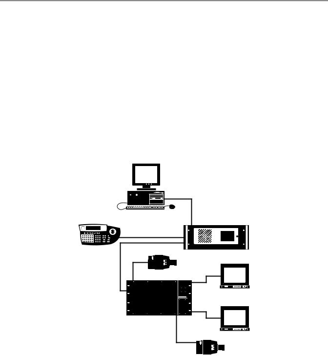
The 9760 system allows control and monitoring of up to 2,048 video input devices (for example, cameras) and 512 video output devices (for example, monitors). The 9760 system consists of the following basic components (refer to Figure 1):
ïCM9700-CC1 central processing unit (CPU): Controls system operation and therefore is also commonly referred to as the controller. Connects to a wide variety of peripheral equipment. Detailed information about the CM9700-CC1 is provided in this manual.
ïCM9760-MXB matrix bay: Performs all video switching functions as directed from the CM9700-CC1. Connects to a maximum of 256 video input devices and 16 video output devices. Detailed information about the CM9760-MXB is provided in this manual.
ïCM9760-KBD keyboard: Provides the user interface to system operations. Detailed information about the CM9760-KBD is provided in the CM9760-KBD/KBR Keyboard Installation/Operation manual.
ïCM9700-MGR system management software: Allows easy system setup and configuration and therefore is also commonly referred to as the System Manager. Requires installation on a PC that meets CM9700-MGR system requirements. Detailed information about the CM9700-MGR software and PC system requirements is provided in the CM9700-MGR Software Guide.
CM9700-MGR
CM9760-KBD |
CM9700-CC1 |
|
CAMERA 1
MONITOR 1
CM9760-MXB
MONITOR 16
CAMERA 256
Figure 1. Basic Components of a 9760 System
NOTE: If your 9760 system includes a CM9760-CC1 that is running version 8.03.xxx or earlier software and you are using CM9760-MGR software, refer to the CM9760-CC1 and CM9760-MGR documentation provided with your system.
In addition to the basic components, you can also use peripheral devices in the 9760 system. Peripheral devices include equipment such as KBD300A/KBD200A keyboards, CM9760-MDA master distribution amplifiers, CM9760-ALM alarm interface units, CM9760-REL relay interface units, Genex® multiplexers, and Pelco® VCRs.
C1572M (9/05) |
9 |
Note the following:
ïTo ensure uninterrupted operation, the 9760 system can be equipped with a backup CM9700-CC1 by means of a CM9760-HS hot switch. For detailed information about the CM9760-HS, refer to the CM9760-HS Hot Switch Installation/Operation manual.
ïThe CM9700-NW1, commonly referred to as the network interface unit (NIU), can be used to connect two or more CM9700-CC1 units to create a networked system. Each CM9700-CC1 unit and attached devices comprise a node in the network. For detailed information about the CM9700-NW1, refer to the System 9760 Networking Guide.
ïYou can increase video output capacity of a single node from 128 to a maximum of 512 by using CM9760-MDA units. For detailed information about the CM9760-MDA, refer to the CM9760-MDA Master Distribution Amplifier Installation/Operation manual.
MODELS
The following provides a list of models of 9760 system devices and compatible equipment.
CPU CONTROLLER AND COMPONENTS
CM9700-CC1 |
CPU controller. Operates on 120 VAC, 60 Hz or 230 VAC, 50 Hz. |
CM9700-SER |
Serial communication (SERCOM) card (RS-422). Provides 8 SERCOM ports to interface peripheral equipment (4 cards |
|
maximum per CM9700-CC1). |
CM9700-SER-32 |
Port expansion unit. Provides 32 SERCOM ports. Includes interconnecting cables and adapters for DB9 and RJ-45 |
|
connectors. Data interface can be RS-232 or RS-422. Up to 3 units can be added to a CM9700-CC1. (Check with Pelco |
|
Systems Applications Department before adding to an existing CM9700-CC1.) |
MATRIX BAY AND COMPONENTS
CM9760-MXB CM9760-MXB-X CM9760-MXBL CM9760-MPS CM9760-MPS-X CM9760-RPC CM9760-RPL CM9760-DFC CM9760-DFL CM9760-VCC
CM9760-RPM
CM9760-VMC4 CM9760-VMC8 CM9760-VMC12 CM9760-VMC16 CM9760-VMM
Video matrix bay equipped with CM9760-MPS power supply. Operates on 120 VAC, 60 Hz.
Same as CM9760-MXB except operates on 230 VAC, 50 Hz.
Video matrix bay for use with CM9760-DFL downframe looping cards. No power required.
Matrix bay power supply (spare). Operates on 120 VAC, 60 Hz.
Matrix bay power supply (spare). Operates on 230 VAC, 50 Hz.
Rear panel input card. Provides 16 BNC connectors to connect video inputs to matrix bay.
Double-wide rear panel card for single-bay looping. Reduces maximum number of inputs to 128.
Downframe rear panel card and cable assembly. Connects multiple matrix bays for expansion purposes.
Downframe rear panel card and cable assembly with BNC connectors for looping video.
Video input card capable of accepting up to 16 video inputs. Also requires a rear panel card (CM9760-DFC, CM9760-DFL, or CM9760-RPC, or CM9760-RPL).
Rear panel output card. Provides 16 BNCs to connect video outputs to matrix bay. Also interfaces video output signals from CM9760-VMC4, CM9760-VMC8, CM9760-VMC12, or CM9760-VMC16 video output card.
Video output card providing 4 video outputs. Requires CM9760-RPM.
Video output card providing 8 video outputs. Requires CM9760-RPM.
Video output card providing 12 video outputs. Requires CM9760-RPM.
Video output card providing 16 video outputs. Requires CM9760-RPM.
Video output module. Expands outputs of CM9760-VMC4, CM9760-VMC8, and CM9760-VMC12 video output cards.
KEYBOARDS
CM9760-KBD* |
Full-function desktop variable-speed keyboard. Operates on 120 VAC, 60 Hz. |
CM9760-KBD-X* |
Same as CM9760-KBD except operates on 230 VAC, 50 Hz. |
CM9760-KBR* |
Full-function 19-inch EIA rack mount keyboard. Operates on 120 VAC, 60 Hz. |
CM9760-KBR-X* |
Same as CM9760-KBR except operates on 230 VAC, 50 Hz. |
KBD300A |
Desktop keyboard with full switching capabilities plus joystick control of PTZ functions. Operates on 12 VAC or |
|
±12 VDC. (Requires KBDKIT for power.) |
KBD200A |
Desktop keyboard with full switching capabilities plus push-button control of PTZ functions. Operates on 12 VAC or |
|
±12 VDC. (Requires KBDKIT for power.) |
*Software version 8.03 or higher is required.
10 |
C1572M (9/05) |
NETWORK INTERFACE UNIT
CM9700-NW1 |
Network CPU and software necessary for joining two or more independent systems together. Allows multiple |
|
systems to share video and control. Commonly referred to as the network interface unit (NIU). |
OPTIONAL COMPONENTS
CM9760-ALM
CM9760-CDU-T
CM9760-CXTA
CM9760-DMR
CM9760-DMR-X CM9760-HS CM9760-MDA
CM9760-MDA-X CM9760-REL
CM9760-VCRC Series
Genex Multiplexers
VMX200 and
VMX300 Series
Alarm interface unit. Connects directly to each system. Each unit can monitor up to 64 alarms. Up to four units can be connected in a series from one SERCOM port.
Code distribution unit. Sixteen-channel RS-422 transmit-only (two data wires and ground) distributor. Primarily used for wiring up to 16 pan/tilt/zoom receivers in a “star” configuration.
Coaxitron® translator. Generates Coaxitron signals for Pelco Coaxitron receivers. Each translator supports up to 16 receivers.
Data merger and port expander unit. Allows multiple CM9700-CC1 units to control multiple pan/tilt/zoom cameras and allows multiple keyboards to communicate through one CM9700-CC1 port.
Same as CM9760-DMR except operates on 230 VAC, 50 Hz.
Hot switch interface unit. Changeover unit that monitors the status of a primary CM9700-CC1 in the system.
Master distribution amplifier. Inserts master time and date from the CM9700-CC1 and a programmable title of up to 24 characters on 1 to 16 video signals.
Same as CM9760-MDA except operates on 230 VAC, 50 Hz.
Relay interface unit. Connects directly to each system and provides dry contact switching for direct or automatic control of peripheral equipment. Each unit provides up to 64 SPST contact outputs.
VCR controllers capable of controlling 64 VCRs.
Genex Series MX4009 (9-channel) and MX4016 (16-channel) multiplexers.
Video management systems. Graphical map/icon-based user interface for mouse-driven operator control from external PC.
COMPATIBLE RECEIVERS
Spectra® Series |
Spectra dome multiple protocol receiver. |
ERD97P21-U |
Pelco P-protocol receiver. |
LRD41C21-1/-2/-3 |
Legacy® fixed speed receiver with presets. |
LRD41C22-1/-2/-3 |
Same as LRD41C21 Series except variable speed receiver. |
Esprit® |
Integrated pan/tilt positioning receiver. |
ExSite™ |
Integrated pan/tilt explosionproof positioning receiver. |
Coaxitron |
Coaxitron translator allows Coaxitron control of PTZ cameras. |
C1572M (9/05) |
11 |

System Setup
This section provides information about the following:
ïOverview of tasks necessary to set up a 9760 system
ïUnpacking the CM9700-CC1 controller and CM9760-MXB matrix bay
ïInstalling the CM9700-CC1 controller
ïInstalling CM9760-MXB matrix bay(s)
ïVerifying system operation
SYSTEM SETUP OVERVIEW
The following provides an overview of the tasks necessary to set up a 9760 system and prepare the system for operation. It is recommended that you perform the tasks in the order listed below.
NOTE: For detailed instructions to perform the tasks listed below for setup of the CM9700-CC1 and CM9760-MXB, refer to the Unpacking, Installing the CM9700-CC1 Controller, and Installing CM9760-MXB Matrix Bay(s) sections in this manual. For detailed instructions to perform the tasks listed below for setup of all other devices in your system, refer to the manual provided for the device.
1.Unpack all equipment. Verify delivery according to the packing slip. Keep all manuals and cables with the associated equipment.
2.Select a location within a standard 19-inch (48.26 cm) EIA rack for each device to be mounted.
3.Mount each device into the selected location within a rack.
DANGER: When mounting equipment into a rack, always install equipment starting from the bottom of the rack. Installing equipment starting from the top of the rack can cause the rack to topple.
4.Verify that the correct number of cards and power supplies have been installed in each CM9760-MXB in the system according to the system order.
5.Install the CM9700-MGR software on a PC, and then do the following:
a.Copy the startconfig.psm file from the CM9700 Factory Configuration Data CD.
b.Open the startconfig.psm file using the CM9700-MGR.
NOTES:
ïThe CM9700-MGR software is contained on the CM9700 Resource CD, which is provided in the System 9760 binder. For CM9700-MGR software installation instructions, refer to the CM9700-MGR Software Guide, which is also provided in the System 9760 binder.
ïThe CM9700 Factory Configuration Data CD is provided in the System 9760 binder.
ïDo not modify the system using the CM9700-MGR until after you have verified system operation in step 12 below.
6.Connect all system devices to the CM9700-CC1 according to the CM9700-CC1 port assignments listed in the System 9760 port assignment table.
NOTE: The System 9760 port assignment table, titled “System 9760 Factory Default Port Settings,” is provided in the System 9760 binder. Detailed information about the System 9760 port assignment table is provided in the Installing the CM9700-CC1 Controller section in this manual.
7.Connect power cabling to all devices.
8.Power on all devices connected to the CM9700-CC1.
9.Power on the CM9700-CC1.
10.Check diagnostic LEDs on devices to ensure that the devices are operating properly.
11.Connect all other cabling—for example, video input and output cabling—to all devices as appropriate.
12.Verify system operation (refer to the Verifying System Operation section in this manual).
12 |
C1572M (9/05) |
UNPACKING
Various items are supplied with the CM9700-CC1 and with the CM9760-MXB. Refer to the Unpacking the CM9700-CC1 and Unpacking the CM9760-MXB sections for a list of items supplied with the units.
UNPACKING THE CM9700-CC1
The following items are supplied with the CM9700-CC1:
1CM9700-CC1 unit, with front rack ears installed
1120 VAC, 60 Hz power cord (USA standard)
1230 VAC, 50 Hz power cord (European standard)
1Keyboard, PS/2
1PS/2-to-AT keyboard adapter
1BNC extraction tool
2Brackets with a set of 6 screws, 8-32 x 0.250-inch, pan head
2 Adjustable support rail sets (each set includes 1 front-mounting rail and 1 rear-mounting rail) and the following sets of screws: 6 Screws, 8-32 x 0.375-inch, pan head with washers
12 Screws, 10-32 x 0.375-inch, flat head
4 Screws, 10-32 x 0.750-inch, Phillips, pan head with washers 6 Screws, 8-32 x 0.250-inch, Phillips, pan head
UNPACKING THE CM9760-MXB
The following items are supplied with the CM9760-MXB:
1 CM9760-MXB matrix bay, with front rack ears installed
1Power cord:
–For the CM9760-MXB: 120 VAC, 60 Hz power cord (USA standard)
–For the CM9760-MXB-X: 230 VAC, 50 Hz power cord (European standard)
NOTE: If the matrix bay is shipped with two power supplies installed, then two 120 VAC or 230 VAC power cords are supplied.
1 RJ-45 reversed data cable
8 Screws and washers for mounting the bay
1 Sheet of video input number labels that can be affixed to the rear panel BNC cards to correspond to video input numbers
In addition, one CM9760-VMC video output card, the appropriate number of CM9760-VCC video input cards, associated rear panel cards, and up to two power supplies are installed in the matrix bay according to your system order.
C1572M (9/05) |
13 |

INSTALLING THE CM9700-CC1 CONTROLLER
Installation of the CM9700-CC1 includes the following tasks:
ïSelecting a location for the CM9700-CC1 in a standard EIA rack
ïMounting the CM9700-CC1
ïConnecting the CM9700-CC1
ïPowering on the CM9700-CC1
To perform each of the above tasks, refer to the sections that follow.
SELECTING A LOCATION FOR THE CM9700-CC1
The CM9700-CC1 is designed to be mounted into a standard 19-inch (48.26 cm) EIA rack. When selecting a location in a rack for the CM9700-CC1, note the following:
ïThe CM9700-CC1 occupies 4 RUs or 7 inches (17.78 cm) of vertical rack space.
ïThe maximum distance allowable between the CM9700-CC1 and a CM9760-MXB is 4,000 feet (1,219 meters).
ïAllow at least 1 RU or 1.75 inches (4.5 cm) of space above the CM9700-CC1 for air circulation.
MOUNTING THE CM9700-CC1
Brackets and support rails are provided to mount the CM9700-CC1 into a rack. The brackets and support rails are provided for your convenience but are not required.
To mount the CM9700-CC1 without the brackets and support rails, fasten each rack ear of the CM9700-CC1 to the rack using two 10-32 x 0.750-inch Phillips pan head screws and washers for each ear.
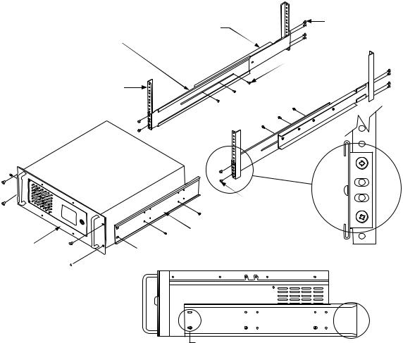
To mount the CM9700-CC1 using the supplied brackets and support rails, refer to Figure 2 and perform the following steps:
1.Attach one bracket to each side of the CM9700-CC1 using three 8-32 x 0.250-inch pan head screws for each side. Attach each bracket so that the slotted holes in the bracket are positioned toward the front of the CM9700-CC1 and the tapered ends of the bracket are positioned toward the rear of the CM9700-CC1.
2.For each set of support rails, attach the front-mounting support rail to the rear-mounting support rail using three 8-32 x 0.375-inch pan head screws and washers for each set. Leave the screws loose until the support rails are attached to the rack.
3.Attach one set of support rails to the equipment rack in the desired location as follows:
a.Position the ear of the front-mounting support rail against the front of the equipment rack and align the holes in the ear of the rail with the threaded holes in the rack. Attach the ear of the rail to the rack using two 10-32 x 0.375-inch flat head screws.
b.Adjust the support rails to the correct depth of the equipment rack by sliding the rear-mounting support rail to the back of the equipment rack.
c.Attach the ear of the rear-mounting support rail to the rear of the equipment rack using four 10-32 x 0.375-inch flat head screws. (The holes in the ear of the rail should align with the threaded holes in the equipment rack.)
4.Tighten the three 8-32 x 0.375-inch pan head screws and washers that were attached to the frontand rear-mounting support rails in step 2 above.
5.Repeat steps 3 and 4 for the second set of support rails.
6.Place the CM9700-CC1 onto the support rails and slide the unit into the rack. The CM9700-CC1 should slide in and out of the rack easily.
DANGER: When sliding the CM9700-CC1 out of the rack, be careful not to let the unit fall out of the rack.
7.Fasten each rack ear of the CM9700-CC1 to the equipment rack using two 10-32 x 0.750-inch Phillips pan head screws and washers for each ear.
14 |
C1572M (9/05) |
REAR MOUNTING |
(8) SCREWS, |
10-32 X 0.375-INCH |
|
SUPPORT RAIL |
FLAT HEAD |
FRONT MOUNTING
SUPPORT RAIL
 (6) SCREWS, 8-32 X 0.375-INCH PAN HEAD WITH
WASHERS
RACK
 (4) SCREWS
10-32 X 0.375-INCH FLAT HEAD
 BRACKET (SIDE VIEW)
CM9700-CC1

 (6) SCREWS, 8-32 X 0.250-INCH PAN HEAD (3 EACH SIDE)
(4) SCREWS, 

10-32 X 0.750-INCH
PHILLIPS, PAN HEAD WITH WASHERS
SLOTTED HOLES |
TAPERED ENDS |
|
|
TOWARDS FRONT |
|
||
TOWARDS REAR |
|||
OF UNIT |
|||
OF UNIT |
|||
|
|||
Figure 2. Mounting the CM9700-CC1
C1572M (9/05) |
15 |
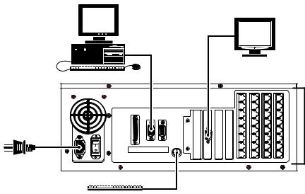
CONNECTING THE CM9700-CC1
System 9760 devices and other equipment connect to the rear panel of the CM9700-CC1 (refer to Figure 3).
CM9700-MGR PC
VGA MONITOR
|
|
|
|
CM9700-CC1 |
|
|
|
36 |
28 |
20 |
12 |
|
|
35 |
27 |
19 |
11 |
|
|
34 |
26 |
18 |
10 |
|
|
33 |
25 |
17 |
9 |
|
|
32 |
24 |
16 |
8 |
POWER CORD |
|
31 |
23 |
15 |
7 |
|
|
30 |
22 |
14 |
6 |
PRINTER |
COM1 |
COM2 |
|
|
|
|
|
29 |
21 |
13 |
5 |
PS/2 KEYBOARD
RS-422 SERCOM PORT CONNECTIONS
Figure 3. CM9700-CC1 Connections
As illustrated in Figure 3, CM9700-CC1 connections include the following:
ïCM9700-MGR PC (RS-232 serial communication)
ïVGA monitor
ïPS/2 keyboard (supplied)
ïSystem devices for RS-422 serial communication (for example, matrix bays, keyboards, and pan/tilt or dome receivers)
ïPower cord (supplied)
For detailed information about each of the above connections, refer to the sections that follow.
NOTE: For detailed information about connecting ASCII communication devices to the CM9700-CC1, refer to Appendix A.
Connecting the CM9700-MGR PC to the CM9700-CC1
NOTES:
ïIt is recommended that you install the CM9700-MGR software on the PC before connecting the PC to the CM9700-CC1. For CM9700-MGR software installation instructions, refer to the CM9700-MGR Software Guide.
ïIf your system is a networked system containing a CM9700-NW1 network interface unit, the CM9700-MGR PC connects to the CM9700-NW1 rather than to a CM9700-CC1.
To connect the CM9700-MGR PC to the CM9700-CC1, refer to Figure 3 and do the following:
1.Using a null modem cable (not provided), connect one end of the cable to the COM 1 or COM 2 DB9 port on the CM9700-MGR PC.
2.Connect the other end of the cable to the COM1 DB9 port on the CM9700-CC1.
NOTE: Either COM 1 or COM 2 on the CM9700-CC1 can be used for connection to the CM9700-MGR PC. COM 1 is configured at the factory for use with the CM9700-MGR PC and RS-232 communication.
Refer to Figure 4 for a diagram of null modem cable wiring connections.
16 |
C1572M (9/05) |
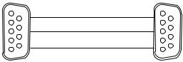
TO CM9700-MGR |
|
TO CM9700-CC1 |
PC COM 1/COM 2 PORT |
|
COM 1/COM 2 PORT |
PIN 3 |
(TX) |
PIN 2 (RX) |
PIN 2 |
(RX) |
PIN 3 (TX) |
PIN 5 (GND) |
PIN 5 (GND) |
|
|
NULL MODEM CABLE (RS-232) |
|
DB9 FEMALE |
|
DB9 FEMALE |
Figure 4. CM9700-MGR PC to CM9700-CC1 Null Modem Cable Connections
Connecting a VGA Monitor to the CM9700-CC1
When connected to the CM9700-CC1, a VGA monitor displays the CM9700-CC1 diagnostic screen (refer to Monitoring CM9700-CC1 Functions in the System Diagnostics section for detailed information about the CM9700-CC1 diagnostic screen).
Connect a VGA monitor to the VGA port of the CM9700-CC1 (refer to Figure 3).
Connecting a PS/2 Keyboard to the CM9700-CC1
A PS/2 keyboard is supplied with the CM9700-CC1. To connect the keyboard to the CM9700-CC1, refer to Figure 3 and do the following:
1.Connect the supplied PS/2-to-AT keyboard adapter to the keyboard.
2.Connect the other end of the adapter to the AT-compatible keyboard port on the CM9700-CC1.
NOTE: An AT-compatible keyboard port also exists on the front of the CM9700-CC1 behind the front door. Both keyboard ports cannot be used at the same time.
Connecting Devices to CM9700-CC1 RS-422 Serial Communication Ports
RS-422 serial communication ports 5-36, commonly referred to as SERCOM ports, are provided on the CM9700-CC1 for communication with devices such as matrix bays, keyboards, and pan/tilt or dome receivers. Before connecting devices to the SERCOM ports, note the following:
ïFor a new system installation, refer to the System 9760 port assignment table titled “System 9760 Factory Default Port Settings” that is provided in the System 9760 binder. The port assignment table lists the CM9700-CC1 ports and the particular device that should be connected to each port as configured at the factory for your system. For additional information about the port assignment table, refer to the
Using the System 9760 Port Assignment Table section.
ïCertain devices must be connected to SERCOM ports in a particular order based on device priority. In a new system installation that has been configured at the factory, connecting devices according to the port assignments provided in the System 9760 port assignment table ensures that you connect the correct device to the correct port.
If you add devices to an existing system, it is recommended that you configure your system using the CM9700-MGR software before connecting devices to SERCOM ports. The CM9700-MGR software automatically assigns devices to SERCOM ports in the correct order. By connecting devices according to the port assignments in CM9700-MGR, you ensure that you connect the correct device to the correct port. For detailed information about SERCOM port device priorities, refer to the SERCOM Port Device Priority Connections section.
To connect a device to a SERCOM port, attach an RJ-45 data cable from the device to the appropriate SERCOM port. An RJ-45 data cable is included with each 9760 system device for connection to the CM9700-CC1. For detailed information about connecting a matrix bay to the CM9700-CC1, refer to the Installing CM9760-MXB Matrix Bay(s) section. For detailed information about connecting an ASCII communication device to the CM9700-CC1, refer to Appendix A. For detailed information about connecting other devices to the CM9700-CC1, refer to the manual supplied with the device.
NOTE: Shielded cabling is required to comply with CE emissions guidelines.
C1572M (9/05) |
17 |

Using the System 9760 Port Assignment Table
The System 9760 port assignment table, titled “System 9760 Factory Default Port Settings,” lists the CM9700-CC1 port numbers (1-36) and each device that has been assigned to a particular CM9700-CC1 port and configured for your system at the factory. Figure 5 illustrates a sample port assignment table for a system containing a CM9700-MGR (System Manager) PC, three CM9760-MXBs, and one CM9760-KBD. Note that the port assignment table for your system will differ from the one shown in Figure 5 depending on the types and number of devices included in your system.
System 9760 Factory Default Port Settings
|
|
|
36 |
|
28 |
|
20 |
|
12 |
|
|
|
|
|
|
|
|
|
|
|
|
|
35 |
27 |
19 |
11 |
|||
|
|
|
|
|
|
|
|
|
|
|
|
|
34 |
26 |
18 |
10 |
|||
|
|
|
|
|
|
|
|
|
|
|
|
|
33 |
25 |
17 |
9 |
|||
|
|
|
|
|
|
|
|
|
|
|
|
|
32 |
24 |
16 |
8 |
|||
|
|
|
|
|
|
|
|
|
|
|
|
|
31 |
23 |
15 |
7 |
|||
|
|
|
|
|
|
|
|
|
|
|
|
|
30 |
22 |
14 |
6 |
|||
PRINTER COM 1 |
COM2 |
|
|
|
|
||||
|
|
|
|
|
|
|
|
||
|
|
|
|
|
|
|
|
|
|
|
|
|
|
|
|
|
|
|
|
|
|
|
29 |
21 |
13 |
5 |
Note: The number of ports on your system may differ from the above drawing. Connect System 9760 components as follows:
PORT |
DESCRIPTION |
PORT |
DESCRIPTION |
1(RS-232) |
SYSTEM MANAGER |
19 |
|
2(RS-232) |
|
20 |
|
|
|
|
|
3 |
NOT AVAILABLE |
|
|
4 |
NOT AVAILABLE |
|
|
5 |
CM9760-MXB (2A) (OUTPUTS 1-16) |
23 |
|
|
|
|
|
6 |
CM9760-MXB (2B) (OUTPUTS 17-32) |
24 |
|
|
|
|
|
7 |
CM9760-MXB (2C) (OUTPUTS 33-48) |
25 |
|
|
|
|
|
8 |
CM9760-KBD (PIN 1111) |
26 |
|
|
|
|
|
9 |
|
27 |
|
|
|
|
|
10 |
|
28 |
|
|
|
|
|
11 |
|
29 |
|
|
|
|
|
12 |
|
30 |
|
|
|
|
|
13 |
|
31 |
|
|
|
|
|
14 |
|
32 |
|
|
|
|
|
15 |
|
33 |
|
|
|
|
|
16 |
|
34 |
|
|
|
|
|
17 |
|
35 |
|
|
|
|
|
18 |
|
36 |
|
|
|
|
|
Figure 5. Sample Port Assignment Table
18 |
C1572M (9/05) |

In the sample port assignment table shown in Figure 5, note the following:
ïCM9700-CC1 port 1 (COM 1) is assigned and configured for the System Manager; therefore, the System Manager PC should be connected to COM 1 on the CM9700-CC1.
NOTE: For all systems configured at the factory, COM 1 is always configured as the port to be used with the System Manager PC.
ïCM9700-CC1 port 2 (COM 2) is not assigned or configured for any device.
ïBecause CM9700-CC1 ports 3 and 4 are not present on the CM9700-CC1, ports 3 and 4 are grayed out and are described as NOT AVAILABLE.
ïCM9700-CC1 port 5 is assigned and configured for the CM9760-MXB labeled 2A containing video outputs 1-16; therefore, the CM9760-MXB labeled 2A should be connected to port 5 on the CM9700-CC1.
ïCM9700-CC1 port 6 is assigned and configured for the CM9760-MXB labeled 2B containing video outputs 17-32; therefore, the CM9760-MXB labeled 2B should be connected to port 6 on the CM9700-CC1.
ïCM9700-CC1 port 7 is assigned and configured for the CM9760-MXB labeled 2C containing video outputs 33-48; therefore, the CM9760-MXB labeled 2C should be connected to port 7 on the CM9700-CC1.
ïCM9700-CC1 port 8 is assigned and configured for the CM9760-KBD having a pin number of 1111; therefore, the CM9760-KBD should be connected to port 8 on the CM9700-CC1.
ïBecause no additional devices are included in the system, CM9700-CC1 ports 9-36 are not assigned or configured for any device.
SERCOM Port Device Priority Connections
The CM9760-HS hot switch, CM9700-NW1 network interface unit (required in a networked system), and CM9760-MXB matrix bays must be connected to SERCOM ports in a particular order based on device priority. The CM9760-HS has the highest priority and, if present in the system, always connects to SERCOM port 5. The CM9700-NW1 has the next highest priority if present in the system, followed by CM9760-MXBs. If neither a CM9760-HS nor a CM9700-NW1 is present, then CM9760-MXBs have the highest priority and must be connected to the CM9700-CC1 starting at port 5. As a result, the order of connections depends on whether the system includes a CM9760-HS hot switch, a CM9700-NW1, or both. Note that CM9760-MXBs must be connected in sequential order. After all CM9760-MXBs have been connected, all other devices—such as keyboards—can then be connected in any order.
Table A, Table B, Table C, and Table D provide a list of the appropriate order of device connections to SERCOM ports in various types of systems. The tables also include the device tree view portion of the CM9700-MGR Main window. The device tree identifies the appropriate port number assigned to each device in the system.
Table A. RS-422 SERCOM Port Connections in a Single-Node System with a CM9760-HS Hot Switch
Device |
SERCOM Port Connection |
CM9700-MGR Device Tree Port Assignments |
|
|
|
CM9760-HS |
Port 5 |
|
|
|
|
CM9760-MXB(s) |
Port 6 and next sequential ports as necessary— |
|
|
connected through the hot switch |
|
|
|
|
Other devices |
Any available ports connected through the hot |
|
|
switch—connections do not have to be in |
|
|
sequential ports |
|
|
|
|
C1572M (9/05) |
19 |
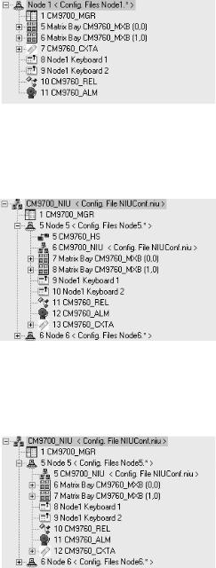
Table B. RS-422 SERCOM Port Connections in a Single-Node System without a CM9760-HS Hot Switch
Device |
SERCOM Port Connection |
CM9700-MGR Device Tree Port Assignments |
|
|
|
CM9760-MXB(s) |
Port 5 and next sequential ports as necessary |
|
|
|
|
Other devices |
Any available ports—connections do not have |
|
|
to be in sequential ports |
|
|
|
|
Table C. SERCOM Port Connections in a Networked System with a CM9760-HS Hot Switch |
||
|
|
|
Device |
SERCOM Port Connection |
CM9700-MGR Device Tree Port Assignments |
|
|
|
CM9760-HS |
Port 5 |
|
|
|
|
CM9700-NW1 |
Port 6—connected through the hot switch |
|
network interface unit |
|
|
|
|
|
Matrix bay(s) |
Port 7 and next sequential ports as necessary— |
|
|
connected through the hot switch |
|
|
|
|
Other devices |
Any available ports connected through the hot |
|
|
switch—connections do not have to be in |
|
|
sequential ports |
|
|
|
|
Table D. SERCOM Port Connections in a Networked System without a CM9760-HS Hot Switch |
||
|
|
|
Device |
SERCOM Port Connection |
CM9700-MGR Device Tree Port Assignments |
|
|
|
CM9700-NW1 network |
Port 5 on each CM9700-CC1 in the network |
|
interface unit |
|
|
|
|
|
Matrix bay(s) |
Port 6 and next sequential ports as necessary |
|
|
|
|
Other devices |
Any available ports—connections do not have |
|
|
to be in sequential ports |
|
|
|
|
NOTE: If you add matrix bays to an existing system, you may need to change existing port connections to be able to connect each additional matrix bay to the lowest sequential port possible.
Connecting Power to the CM9700-CC1
To connect power to the CM9700-CC1, connect the supplied 120 VAC or 230 VAC power cord to the power input receptacle on the CM9700-CC1 and to an approved power source.
NOTE: Do not power on the CM9700-CC1 until all system devices have been connected to the CM9700-CC1 and all system devices have been powered on.
20 |
C1572M (9/05) |
POWERING ON THE CM9700-CC1
After all system devices have been connected to the CM9700-CC1 and all system devices have been powered on, power on the CM9700-CC1. To power on the unit, place the power switch in the On (I) position. If, for some reason, you must power off the unit, place the power switch in the Off (0) position.
INSTALLING CM9760-MXB MATRIX BAY(S)
Your System 9760 installation may include one or multiple CM9760-MXB matrix bays. Installation of a CM9760-MXB includes the following tasks:
ïSelecting a location for the CM9760-MXB in an EIA standard rack
ïMounting the CM9760-MXB
ïVerifying CM9760-MXB component installation
ïConnecting the CM9760-MXB to the CM9700-CC1
ïConnecting power to the CM9760-MXB
ïPowering on the CM9760-MXB
ïChecking diagnostic LEDs
ïConnecting video inputs and outputs
To perform each of the above tasks, refer to the sections that follow.
SELECTING A LOCATION FOR THE CM9760-MXB
The CM9760-MXB is designed to be mounted into a standard 19-inch (48.26 cm) EIA rack. When selecting a location in a rack for a CM9760-MXB, note the following:
ïThe CM9760-MXB occupies 6 RUs or 10.5 inches (26.7 cm) of vertical rack space.
ïAllow at least 1 RU or 1.75 inches (4.5 cm) of space above the CM9760-MXB for air circulation. In a high-temperature environment, it may also be necessary to provide forced air cooling. Contact Product Support for additional information.
ïThe maximum distance allowable between a CM9760-MXB and the CM9700-CC1 is 4,000 feet (1,219 meters). Note that a 10-foot
(3.05 meters) reversed cable is supplied with the CM9760-MXB for connection to the CM9700-CC1. If you install a CM9760-MXB farther than 10 feet from the CM9700-CC1, you must create your own cable.
In addition, if you are installing multiple matrix bays, note the following:
ïWhen expanding video inputs beyond 256 as provided by a single matrix bay, the expansion of video inputs occurs in a horizontal manner using a sideframing configuration. As a result, each additional matrix bay should be installed at the same level in a nearby rack.
When installing a new system containing multiple matrix bays to be sideframed, note that the rear of each matrix bay is labeled to identify the location of each matrix bay in the sideframe configuration. For example, the matrix bays are labeled 2A, 12A, 22A, and so on.
ïWhen expanding video outputs beyond 16 as provided by a single matrix bay, the expansion of video outputs occurs in a vertical manner using a downframing configuration. As a result, multiple matrix bays must be installed in the same rack.
When installing a new system containing multiple matrix bays to be downframed, note that the rear of each matrix bay is labeled to identify the location of each matrix bay in the downframe configuration. For example, the matrix bays are labeled 2A, 2B, 2C, and so on.
ïWhen expanding video inputs beyond 256 and video outputs beyond 16, a combination of sideframing and downframing is used.
When installing a new system containing multiple matrix bays to be sideframed and downframed, note that the rear of each matrix bay is labeled to identify the location of each matrix bay in the sideframe and downframe configuration. For example, matrix bays to be sideframed are labeled 2A, 12A, 22A, and so on; and matrix bays to be downframed are labeled 2B, 12B, 22B, and so on.
To help you determine the location of multiple matrix bays in your system, refer to Appendix B for sample illustrations of matrix bay configurations. Note the labeling of the matrix bays shown in the sample illustrations. In addition, for detailed information about sideframing and downframing, refer to Sideframing and Downframing in the CM9760-MXB Matrix Bay section.
C1572M (9/05) |
21 |

MOUNTING THE CM9760-MXB
DANGER: Always install equipment starting from the bottom of the rack. Installing equipment starting from the top of the rack can cause the rack to topple.
To mount a CM9760-MXB into a rack, install the CM9760-MXB into the desired location and secure the unit using the supplied mounting hardware (refer to Figure 6).
Figure 6. Mounting the CM9760-MXB
If you are mounting multiple matrix bays, note the following:
ïIf you are installing a new system, be sure to mount the matrix bays in a horizontal (sideframe) or vertical (downframe) manner according to the bay location label provided on the rear of each matrix bay (refer to the Selecting a Location for the CM9760-MXB section for additional information.)
ïAfter mounting matrix bays in a downframe configuration, connect each supplied coaxial ribbon cable, referred to as a downframe cable, to downframe connectors on rear panel cards as appropriate. The downframe cables are required to connect the video inputs from one matrix bay to another. Figure 7 illustrates sample downframe cable connections between a CM9760-RPC card and a CM9760-DFC card and between a CM9760-RPC card and a CM9760-DFL card in a configuration containing one downframed bay. For additional information, refer to Downframing in the CM9760-MXB Matrix Bay section and to Appendix B.
22 |
C1572M (9/05) |

CM9760-MXB BAY 1
CM9760-MXB BAY 2
Alarm |
Black |
|
Out |
RS-422
RS-422
Alarm |
Black |
|
Out |
RS-422
RS-422
CAMS |
|
|
1-256 |
RPC |
RPC |
|
SUPPLIED DOWN-
OR
FRAMING CABLES 16X RIBBON COAXIAL
DFC |
DFL |
|
Figure 7. Sample Downframe Cable Connections
VERIFYING CM9760-MXB COMPONENT INSTALLATION
Up to 16 CM9760-VCC video input cards, one CM9760-VMC video output card, and up to two power supplies are installed in a matrix bay at the factory as ordered. Verify component installation as follows:
1.Remove the front panel of the matrix bay to view the video input and output cards.
2.Verify that the correct number of cards and power supplies are installed. In addition, verify that each installed card and power supply is properly seated in the matrix bay.
Refer to the following sections for detailed information.
C1572M (9/05) |
23 |
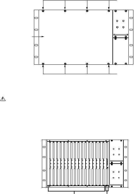
Removing the CM9760-MXB Front Panel
To remove the front panel of the CM9760-MXB, loosen the eight captive panel screws indicated in Figure 8.
CAPTIVE PANEL
SCREW (4)
FRONT
PANEL
CAPTIVE PANEL
SCREW (4)
Figure 8. CM9760-MXB Front Panel
WARNING: Although the CM9760-MXB will function properly with the front panel removed, the front panel must be attached during system operation to meet safety standards. To reattach the front panel, tighten the eight captive panel screws.
Verifying Input Card, Output Card, and Power Supply Installation
The CM9760-MXB accepts up to 16 CM9760-VCC video input cards in slots 1-16, one CM9760-VMC card in slot 17, and up to two power supplies (refer to Figure 9). With the front panel removed, verify that the correct number of cards are installed as ordered and that they are firmly seated in the appropriate slots. In addition, verify that the correct number of power supplies are installed as ordered and that each installed power supply is firmly seated in the power supply slot.
+10V -10V
FRAME SUPPLY
FAULT FAULT
+10V -10V
FRAME SUPPLY
FAULT FAULT
CM9760-VCC |
CM9760-VMC |
VIDEO INPUT |
VIDEO OUTPUT |
CARDS |
CARD |
(SLOTS 1-16) |
(SLOT 17) |
Figure 9. Sample CM9760-MXB Configuration
NOTE: The configuration of your CM9760-MXB may differ from the configuration shown in Figure 9 depending on the number of video input cards and power supplies ordered. If your configuration contains only one power supply, a blank plate covers the lower power supply slot.
24 |
C1572M (9/05) |
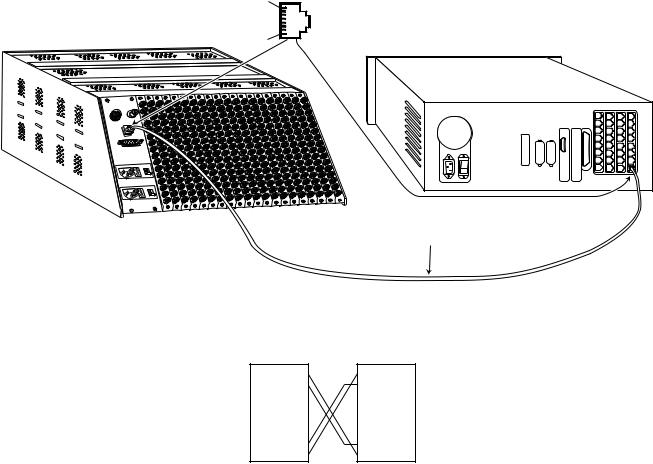
CONNECTING THE CM9760-MXB TO THE CM9700-CC1
Connect a CM9760-MXB to the CM9700-CC1 using the 10-foot (3.05 meters) reversed cable supplied with the CM9760-MXB. If you must create a longer cable, it is recommended that you use a 24-gauge twisted pair cable.
As illustrated in Figure 10, connect the female RJ-45 serial communications data port labeled RS-422 on the rear of the CM9760-MXB to the appropriate female RJ-45 serial communications port (RS-422) on the rear of the CM9700-CC1. Figure 10 provides an example of a CM9760-MXB connected to port 5 on the CM9700-CC1.
8-PIN SERCOM PORT (FEMALE) |
|
||
PIN 1 |
PIN 1=Tx+ |
|
|
PIN 2=Tx– |
|
||
|
. |
|
|
|
. |
|
|
CM9760-MXB (FULLY LOADED) |
. |
|
|
PIN 7=Rx– |
|
||
PIN 8 |
|
||
PIN 8=Rx+ |
CM9700-CC1 |
||
|
|||
REVERSED DATA CABLE (SUPPLIED)
RS-422
DATA CABLE CONNECTIONS
CM9760-MXB |
CM9700-CC1 |
RJ-45 |
RJ-45 |
CONNECTOR |
CONNECTOR |
PIN 1=Tx+ |
PIN 1=Tx+ |
PIN 2=Tx– |
PIN 2=Tx– |
. |
. |
. |
. |
. |
. |
. |
. |
PIN 7=Rx– |
PIN 7=Rx– |
PIN 8=Rx+ |
PIN 8=Rx+ |
Figure 10. CM9760-MXB to CM9700-CC1 Connection
C1572M (9/05) |
25 |

CONNECTING POWER TO THE CM9760-MXB
NOTE: A CM9760-MXB operates on 120 VAC, 60 Hz. A CM9760-MXB-X operates on 230 VAC, 50 Hz.
To connect power to a CM9760-MXB, plug the supplied power cord into the power input receptacle on the rear of the matrix bay for each power supply installed (refer to Figure 11). Then plug the power cord for each installed power supply into an approved power source.
POWER CORD CONNECTION TO UPPER POWER SUPPLY
POWER SWITCH FOR UPPER POWER SUPPLY
POWER SWITCH FOR  LOWER POWER SUPPLY
Alarm |
Black |
|
Out |
RS-422
RS-422
POWER CORD CONNECTION
TO LOWER POWER SUPPLY
Figure 11. CM9760-MXB Power Connections (Two Power Supplies Installed)
POWERING ON THE CM9760-MXB
NOTE: Do not power on the CM9760-MXB until after it is connected to the CM9700-CC1.
To power on a CM9760-MXB, place the corresponding power switch of each installed power supply in the On (I) position. If, for some reason, you must power off the CM9760-MXB, place the corresponding power switch of each installed power supply in the Off (0) position.
CHECKING DIAGNOSTIC LEDS
Checking the diagnostic LEDs on a CM9760-MXB allows you to ensure that the unit is operating properly. It is recommended that you check the LEDs on the CM9760-MXB before connecting video inputs and outputs to the unit.
With the CM9760-MXB powered on, check the LEDs as follows:
1.For each power supply installed, do the following:
a.Verify that the +10V and –10V power LEDs are lit (green).
If a power LED is not lit, ensure that the power supply is seated properly. If the condition persists, inspect the power supply fuse and replace the fuse if necessary (refer to Replacing a Power Supply Fuse in the CM9760-MXB Component Installation or Replacement section for detailed instructions).
b.Verify that the Frame Fault and the Supply Fault LEDs are not lit.
If the Frame Fault LED is lit (red), one or more video input/output cards has failed. Continue with step 2 for troubleshooting information.
If the Supply Fault LED is lit (red), replace the power supply (refer to Replacing a Power Supply in the CM9760-MXB Component Installation or Replacement section for detailed instructions).
26 |
C1572M (9/05) |
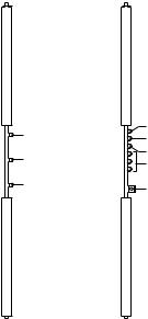
2.With the front panel of the CM9760-MXB removed, check the LEDs on the CM9760-VCC video input cards and on the CM9760-VMC video output card as follows (refer to Figure 12):
a.Verify that all +10 VDC and –10 VDC power LEDs are lit (green).
If a power LED is not lit, remove the card and inspect the fuses (refer Figure 13 for fuse locations on CM9760-VCC and CM9760-VMC cards). Replace fuse(s) if necessary. If the condition continues, replace the card. For instructions to replace a CM9760-VCC or CM9760-VMC card, refer to Replacing a CM9760-VCC Card or to Replacing a CM9760-VMC Card in the CM9760-MXB Component Installation or Replacement section as applicable.
b.Verify that all Comm Fail LEDs are not lit:
ïIf the LED is lit (red) on any video input card, reseat the card. If the condition continues, replace the card.
ïIf the Comm Fail LED is lit (red) on the video output card only, check the communication to the CM9700-CC1.
ïIf all Comm Fail LEDs are lit (red), press the Reset button located on the video output card (refer to Figure 12). If the problem continues, replace the video output card.
For a summary of troubleshooting information relating to the CM9760-MXB, refer to Troubleshooting the CM9760-MXB in the Troubleshooting section.
After you have verified that the CM9760-MXB is operating properly, reattach the front panel of the CM9760-MXB. Then connect video inputs and outputs (refer to the Connecting Video Inputs and Video Outputs section).
COMM FAIL |
COMM FAIL |
|
+10 VDC |
||
|
||
+10 VDC |
-10 VDC |
|
NO ASSIGNMENT |
||
|
||
-10 VDC |
RESET BUTTON |
|
|
CM9760-VCC |
CM9760-VMC |
VIDEO INPUT CARD |
VIDEO OUTPUT CARD |
Figure 12. CM9760-VCC and CM9760-VMC Diagnostic LEDs
C1572M (9/05) |
27 |
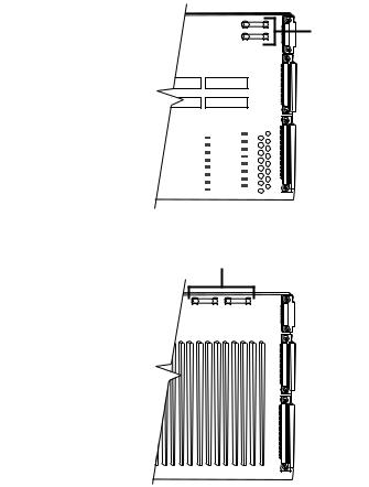
.7ASB FUSES |
CM9760-VCC
VIDEO
INPUT
CARD
.7ASB FUSES
CM9760-VMC
VIDEO
OUTPUT
CARD
Figure 13. Fuse Locations on CM9760-VCC and CM9760-VMC Cards
28 |
C1572M (9/05) |
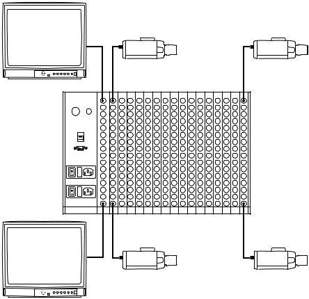
CONNECTING VIDEO INPUTS AND VIDEO OUTPUTS
Connect all video inputs (up to 256) and all video outputs (up to 16) to the rear panel BNC cards (refer to Figure 14).
1
241 |
1 |
Alarm Black
Out
RS-422
RS-422
16 |
256 |
16 |
|
Figure 14. CM9760-MXB Video Input and Output Connections
Note the following:
ïTo provide adequate ground and signal connections, use crimp-on BNCs rather than screw-on BNCs.
ïAllow enough slack in a cable to act as a strain relief between the cable and the BNC connectors.
ïBe sure each connection is secure.
ïLabel all cabling to minimize system downtime if troubleshooting becomes necessary and cabling needs to be disconnected.
ïVideo output from the CM9760-VMC video output card is not terminated. Terminate the video signal at the output device (for example, monitor,VCR, or matrix switcher). If you are looping to other devices, terminate the last device only.
ïThe endpoint of any video cable run must be teminated in 75 ohms.
ïFor information about sideframing video inputs and downframing video outputs, refer to Sideframing and Downframing in the
CM9760-MXB Matrix Bay section.
C1572M (9/05) |
29 |
VERIFYING SYSTEM OPERATION
After installation of the 9760 system is complete, verify system operation. To do so, perform the following from a CM9760-KBD:
1.Verify that the CM9760-KBD LCD displays the following: SYSTEM 97XX
NOTE: Depending on the version of the CM9760-KBD software, the LCD displays SYSTEM 9760 or SYSTEM 9700.
2.Enter the default operator password on the CM9760-KBD keypad: The default password for operator 1 is 0101; the default password for operator 2 is 0202; the default password for operator 3 is 0303, and so on. The passwords are defined in the Operator PIN field in CM9700-MGR.
The LCD displays the following: ENTER MONITOR #
3.Enter the number of the monitor you are viewing—for example, 1—and then press the MON key.
4.Enter a camera number, and then press the CAM key.
5.Press the FWD key to advance through cameras and verify switching.
For detailed information about 9760 system operation using the CM9760-KBD, refer to the CM9760-KBD/KBR Keyboard Installation/Operation manual.
30 |
C1572M (9/05) |
Loading...