


PP451

IMPORTANT SAFEGUARDS AND WARNINGS
Prior to installation and use of this product, the following WARNINGS should be observed.
1. Installation and servicing should only be done by qualified service personnel and conform
to all local codes.
2. Installation shall be done in accordance with all local and national electrical and mechani-
cal codes utilizing only approved materials.
3. Use only installation methods and materials capable of supporting four times the maxi-
mum specified load.
4. Use stainless steel hardware to fasten the mount to outdoor surfaces.
5. To prevent damage from water leakage when installing a mount outdoors on a roof or
wall, apply sealant around the bolt holes between the mount and mounting surface.
Please thoroughly familiarize yourself with the information in this manual prior to installation
and operation.
C212M-B (8/04)
PP350/PP450 Parapet Mount
PP351/PP451 Rooftop Mount
3500 Pelco Way,
Clovis, CA 93612-5699
USA
In North America & Canada:
Tel (800) 289-9100
FAX (800) 289-9150
International Customers:
Tel (1-559) 292-1981
FAX (1-559) 348-1120
www.pelco.com
®
DESCRIPTION
The PP350 and PP351 mounts were designed for outdoor use with small-size pendant domes,
and the PP450 and PP451 are for outdoor use with medium-size pendant domes. The PP350
and PP450 models mount to parapets, while the PP351 and PP451 models mount to rooftops
or other smooth horizontal surfaces. All models accommodate domes that use 1.5-inch NPT
pipe.
The PP450 and PP451 can be used in applications where mounting and height clearances of
models PP350 and PP351 are inadequate. Models PP450 and PP451 are higher by 9.72
inches (24.69 cm) and the overhang is increased by 14.77 inches (37.52 cm).
The mounts are designed to swivel within available clearance limits, which adds to the flexibility,
easy maintenance, and usability of the configuration.
Manufactured from aluminum, the mounts include indexing bolts to secure the arm in position.
Models
PP350 Parapet mount for small-size pendant domes; mounts to inside or outside of
parapet.
PP351 Rooftop or smooth horizontal surface mount for small-size pendant domes .
PP450 Same as PP350 except overhang clearance and height accommodate medium-
size pendant domes.
PP451 Same as PP351 except overhang clearance and height accommodate medium-
size pendant domes.
INSTALLATION
Before Beginning
The hardware to install the mount depends on your installation requirements. The mount has
pre-drilled holes for use with 3/8-16 type hardware. (This hardware is not included with the
mount.) Use as many of the mounting holes as possible. Pelco recommends 3/8-16 type fasten-
ing hardware. Multiple fastening positions facilitate mounting flexibility. For models PP350 and
PP450, mount using a minimum of three fasteners on each side of the mounting plate. For
models PP351 and PP451, mount using a minimum of two fasteners on each side of the
mounting base. If necessary to prevent damage from water leakage, you should also have seal-
ant (not supplied) to apply around the bolt holes between the mount and mounting surface.
Installing the Mount
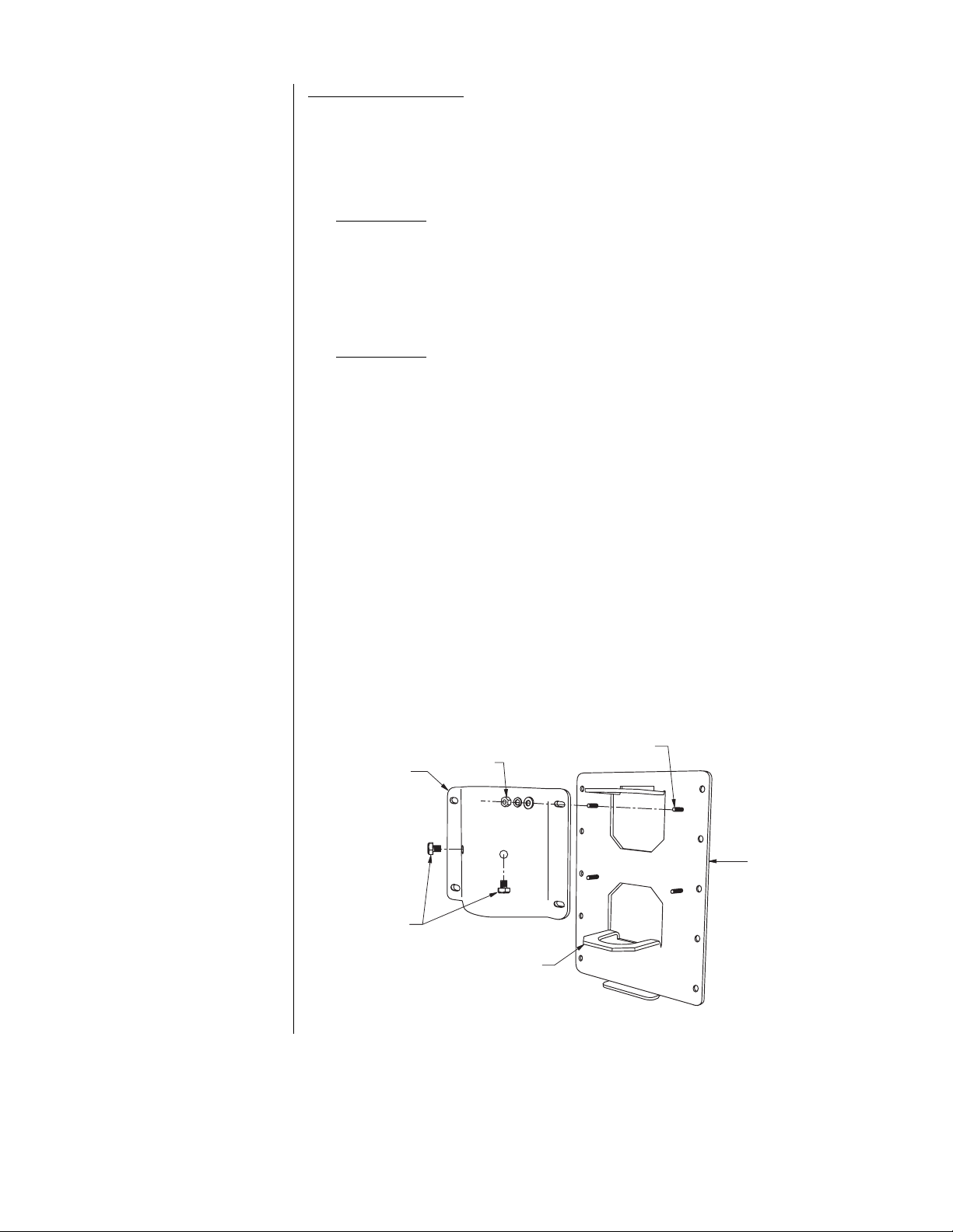
1. Loosen the nuts holding the brake mounting plate. Loosen the nuts only enough to pull
the arm out of the guide hoops (see Figure 1).
2. Remove the arm.
3. Install the mount.
PP350/PP450
Install the mounting plate to the inside or the outside of the parapet. Use a minimum of
three fasteners on each side of the mounting plate. Depending on the type of parapet
construction, install the mounting plate as close to the top of the parapet as possible. If
the mounting plate is installed two to five inches from the top of the parapet, you can
swing the dome back for maintenance as necessary (the dome will clear the top of the
parapet). If necessary to prevent water damage, apply sealant around the bolt holes be-
tween the mount and mounting surface.
PP351/PP451
Install the mounting base to the rooftop or other smooth horizontal surface. Use a mini-
mum of two fasteners on each of the four sides of the mounting base (a minimum total of
eight fasteners). If necessary to prevent water damage, apply sealant around the bolt
holes between the mount and mounting surface.
4. Reinstall the arm; lower the arm through the guide hoops until it stops at the bottom of
the mounting plate.
5. Pull the wires through the arm starting from the bottom of the mounting plate; pull the
wires out through the threaded opening at the top of the arm.
6. Pull the wires through the dome, and attach the dome to the end of the arm.
7. Make all electrical connections.
8. Move the arm and dome into the desired position.
9. Secure the brake mounting plate against the arm; tighten the nuts on the studs that hold
the brake mounting plate in place.
10. To hold the arm in position, tighten the indexing bolts near the center of the brake mount-
ing plate. If desired, drill into the arm through the holes in the brake mounting plate, install
the indexing bolts, and tighten. Important . . . Do not drill into existing wiring
that may be pulled through the arm.
BRAKE
MOUNTING
PLATE
INDEXING
BOLTS
GUIDE HOOP
MOUNTING
PLATE
STUD
NUT
Figure 1. Mounting Diagram
 Loading...