

Page 1
C1430M-D (8/01)
CM9505J Junction Box
CM9505UPS Universal Power Supply
®
3500 Pelco Way
Clovis, CA 93612-5699
USA
In North America & Canada:
Tel (800) 289-9100
FAX (800) 289-9150
International Customers:
Tel +1(559) 292-1981
FAX +1(559) 348-1120
www.pelco.com
IMPORTANT SAFEGUARDS AND WARNINGS
Prior to installation and use of this product, the following WARNINGS should be observed.
1. Installation and servicing should only be done by qualified service personnel and conform
to all local codes.
2. Unless the unit is specifically marked as a NEMA Type 3, 3R, 3S, 4, 4X ,6 or 6P enclosure,
it is designed for indoor use only.
3. To reduce risk of fire or electric shock, do not expose this product to rain or moisture.
4. Only use replacement parts recommended by Pelco.
The product and/or manual may bear the following marks:
This symbol indicates that dangerous voltage constituting a risk of
electric shock is present within this
unit.
This symbol indicates that there
are important operating and maintenance instructions in the literature accompanying this unit.
Please thoroughly familiarize yourself with the information in this manual prior to installation and
operation.
CAUTION:
RISK OF ELECTRIC SHOCK.
DO NOT OPEN.
DESCRIPTION
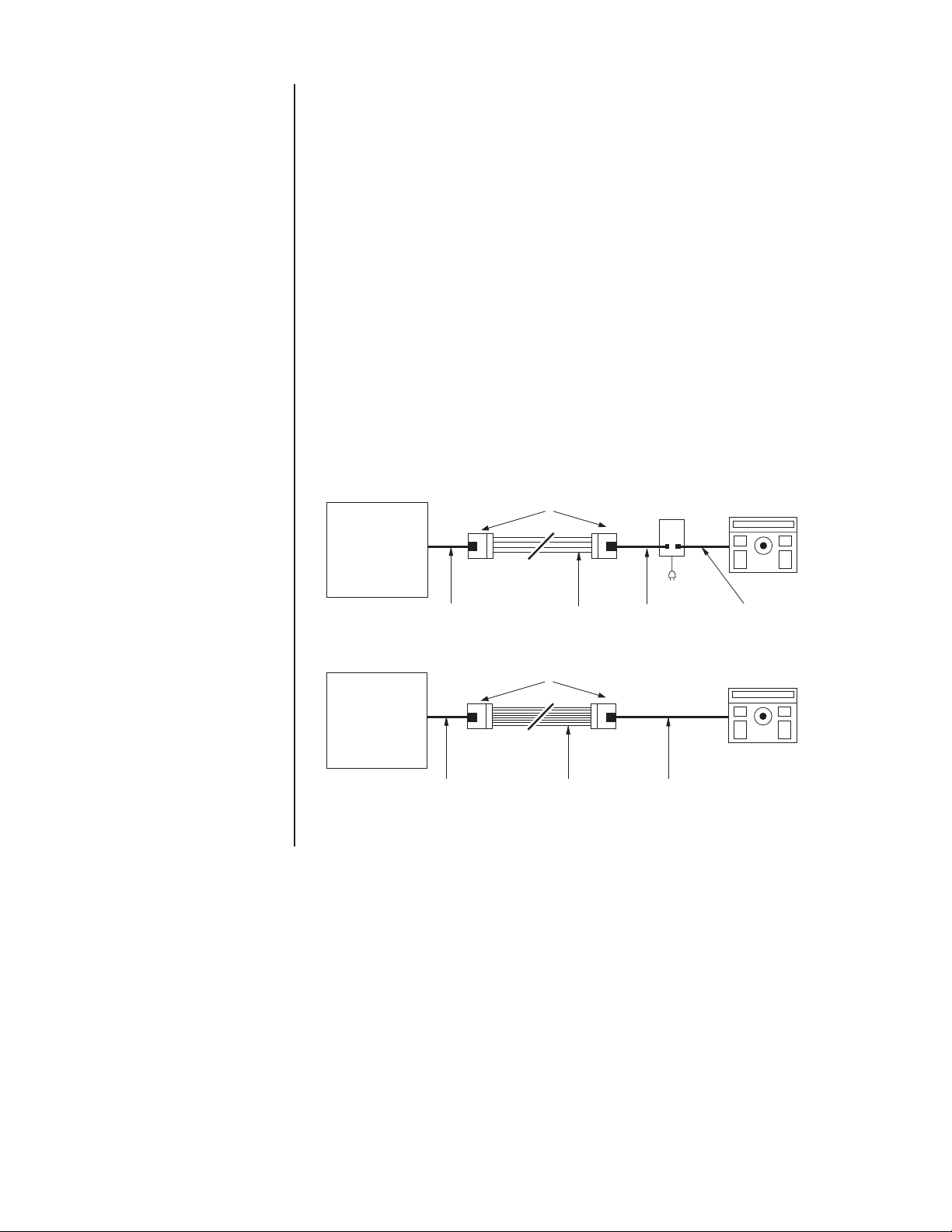
The CM9505J Junction Box and the CM9505UPS Universal Power Supply are used with
CM8500 and CM9500 matrix systems to allow the system keyboards to be placed at remote
locations throughout a facility.
The junction box can be used by itself, but in most applications is used in conjunction with the
power supply (refer to Figure 1). When used together, the junction box allows you to convert a
keyboard cable into a set of cabling that can be run significantly greater distances by eliminating
the keyboard power connections and only running the data. The CM9505UPS Universal Power
Supply reintroduces the keyboard power at the keyboard end of the cabling. For distances over
2,000 feet (609.6 m), the CM9505UPS-422 Universal Power Supply with data repeater is recommended.
Communication between each keyboard and the CPU consists of two RS-422 data pairs,
+12 VDC, -12 VDC, and a ground, for a total of seven conductors. The junction boxes, power
supplies, and keyboards are supplied with 25-foot (7.6 m) pretested interconnect cables with
pre-assembled RJ-45 modular 8-pin male connectors.
Models
CM9505J Junction box only, for CM8500 and CM9500 matrix system keyboards
CM9505UPS Power supply only, for CM8500 and CM9500 matrix system keyboards
CM9505UPS-X Same as CM9505UPS, except 230 VAC (CE)
CM9505UPS-422 Same as CM9505UPS, except with data repeater function (FCC, UL, cUL)
CM9505UPS-422X Same as CM9505UPS-422, except 230 VAC (CE)
(UL, cUL)
Page 2
INSTALLATION
The following parts are supplied:
2 CM9505J Junction Boxes with 25-foot (7.6 m) data cable, or
1 CM9505UPS Series Universal Power Supply with 25-foot (7.6 m) data cable
1. Connect either a four-conductor or eight-conductor cable (not supplied) between the
junction boxes, depending on whether you will install a CM9505UPS Series power supply
(refer to Figure 1).
Refer to Table A for the wiring assignments and to Figure 2 for the terminal locations. If
you are using a four-conductor cable, connect the wires to terminals 1, 2, 7, and 8 only.
Refer to Table B for the maximum cable distances if you use an eight-conductor cable
between the junction boxes. The maximum length is limited by the distance restrictions of
the DC power lines.
If you use a four-conductor cable and the CM9505UPS power supply, the maximum cable
distance between the junction boxes is 2,000 feet (610 m). For distances over 2,000 feet
(610 m), the CM9595UPS-422 power supply with data repeater is recommended.
2. Connect the 25-foot (7.6 m) cables (supplied) between the junction boxes, power supply,
and matrix system card cage as applicable (refer to Figure 1).
3. Plug the power supply into the wall outlet.
MATRIX SYSTEM
CARD CAGE
DATA CABLE SUPPLIED
WITH JUNCTION BOX
MATRIX SYSTEM
CARD CAGE
DATA CABLE SUPPLIED
WITH JUNCTION BOX
CM9505J
JUNCTION BOX
USER SUPPLIED
4-CONDUCTOR
CM9505J
JUNCTION BOX
USER SUPPLIED
8-CONDUCTOR
CM9505UPS
DATA CABLE
SUPPLIED WITH
UPS
DATA CABLE
SUPPLIED WITH
KEYBOARD
Figure 1. CM9505UPS/CM9505J Configuration
REMOTE KEYBOARD
DATA CABLE
SUPPLIED WITH
KEYBOARD
REMOTE KEYBOARD
Page 3

Table A. CPU and Keyboard Terminal Assignments
CPU Keyboard
Terminal Function Function Terminal
1 Data in + Data out + 1
2 Data in - Data out - 2
3 -12 VDC -12 VDC 3
4 +12 VDC +12 VDC 4
5 Ground Ground 5
6 Spare Spare 6
7 Data out - Data in - 7
8 Data out + Data in + 8
45
3
2
1
6
7
8
Figure 2. Wall Block Terminal Assignments
Table B. Data/Power Cable Distances
Wire Gauge Feet/Meters
14 832 / 254
16 416 / 127
18 275 / 84
20 166 / 51
22 104 / 32
Page 4

REGULATORY NOTICES
NOTE: This equipment has been tested and found to comply with the limits of a Class A digital
device, pursuant to part 15 of the FCC rules. These limits are designed to provide reasonable
protection against harmful interference when the equipment is operated in a commercial environment. This equipment generates, uses, and can radiate radio frequency energy and, if not installed and used in accordance with the instruction manual, may cause harmful interference to
radio communications. Operation of this equipment in a residential area is likely to cause harmful
interference in which case the user will be required to correct the interference at his own expense.
PRODUCT WARRANTY AND RETURN INFORMATION
WARRANTY
Pelco will repair or replace, without charge, any merchandise proved defective in material or
workmanship for a period of one year after the date of shipment.
Exceptions to this warranty are as noted below:
• Five years on FT/FR8000 Series fiber optic products.
®
• Three years on Genex
• Three years on Camclosure® and fixed camera models, except the CC3701H-2,
CC3701H-2X, CC3751H-2, CC3651H-2X, MC3651H-2, and MC3651H-2X camera models,
which have a five-year warranty.
•Two years on standard motorized or fixed focal length lenses.
•Two years on Legacy
fixed dome products.
•Two years on Spectra
continuous motion applications.
•Two years on Esprit
• Eighteen months on DX Series digital video recorders, NVR300 Series network video
recorders, and Endura
• One year (except video heads) on video cassette recorders (VCRs). Video heads will be
covered for a period of six months.
• Six months on all pan and tilts, scanners or preset lenses used in continuous motion
applications (that is, preset scan, tour and auto scan modes).
Pelco will warrant all replacement parts and repairs for 90 days from the date of Pelco
shipment. All goods requiring warranty repair shall be sent freight prepaid to Pelco, Clovis,
California. Repairs made necessary by reason of misuse, alteration, normal wear, or accident
are not covered under this warranty.
Pelco assumes no risk and shall be subject to no liability for damages or loss resulting from
the specific use or application made of the Products. Pelco’s liability for any claim, whether
based on breach of contract, negligence, infringement of any rights of any party or product
liability, relating to the Products shall not exceed the price paid by the Dealer to Pelco for
such Products. In no event will Pelco be liable for any special, incidental or consequential
damages (including loss of use, loss of profit and claims of third parties) however caused,
whether by the negligence of Pelco or otherwise.
The above warranty provides the Dealer with specific legal rights. The Dealer may also have
additional rights, which are subject to variation from state to state.
Series products (multiplexers, server, and keyboard).
®
, CM6700/CM6800/CM9700 Series matrix, and DF5/DF8 Series
®
, Esprit®, ExSite™, and PS20 scanners, including when used in
®
and WW5700 Series window wiper (excluding wiper blades).
™
Series distributed network-based video products.
If a warranty repair is required, the Dealer must contact Pelco at (800) 289-9100 or
(559) 292-1981 to obtain a Repair Authorization number (RA), and provide the following
information:
1. Model and serial number
2. Date of shipment, P.O. number, Sales Order number, or Pelco invoice number
3. Details of the defect or problem
If there is a dispute regarding the warranty of a product which does not fall under the
warranty conditions stated above, please include a written explanation with the product
when returned.
Method of return shipment shall be the same or equal to the method by which the item was
received by Pelco.
RETURNS
In order to expedite parts returned to the factory for repair or credit, please call the factory at
(800) 289-9100 or (559) 292-1981 to obtain an authorization number (CA number if returned
for credit, and RA number if returned for repair).
All merchandise returned for credit may be subject to a 20% restocking and refurbishing
charge.
Goods returned for repair or credit should be clearly identified with the assigned CA or RA
number and freight should be prepaid. Ship to the appropriate address below.
If you are located within the continental U.S., Alaska, Hawaii or Puerto Rico, send goods to:
Service Department
Pelco
3500 Pelco Way
Clovis, CA 93612-5699
If you are located outside the continental U.S., Alaska, Hawaii or Puerto Rico and are
instructed to return goods to the USA, you may do one of the following:
If the goods are to be sent by a COURIER SERVICE, send the goods to:
Pelco
3500 Pelco Way
Clovis, CA 93612-5699 USA
If the goods are to be sent by a FREIGHT FORWARDER, send the goods to:
Pelco c/o Expeditors
473 Eccles Avenue
South San Francisco, CA 94080 USA
Phone: 650-737-1700
Fax: 650-737-0933
REVISION HISTORY
Manual # Date Comments
C1430M Original version.
C1430M-A 11/98 Changed manual to new format. Revised installation instructions and added Figure 4 per PAR #98019.
C1430M-B 7/99 Incorporated ECO 99-4999 . Updated to new format.
C1430M-C 6/01 Revised to include safety warning and updated warranty information.
C1430M-D 8/01 Revised to include UL and cUL markings.
® Pelco, the Pelco logo, Spectra, Genex, Legacy, and PelcoVision are registered trademarks of Pelco. © Copyright 2001, Pelco.
™ Esprit and Camclosure are trademarks of Pelco. All rights reserved.
 Loading...