

Page 1
®
Breakout Panels for
VA6000 Series Switcher
and CM8500 Matrix System
Installation/Operation
Manual C842M (9/96)
PELCO • 3500 Pelco Way, Clovis, CA 93612-5699 • USA • (800) 289-9100 or (1-559) 292-1981
FAX (800) 289-9150 or (1-559) 292-3827
Page 2

TABLE OF CONTENTS
Section Page
1.0 WARNINGS ........................................................................................................................................1
2.0 SCOPE ............................................................................................................................................... 2
3.0 DESCRIPTION ................................................................................................................................... 2
4.0 INSTALLATION ..................................................................................................................................2
5.0 MODELS .......................................................................................................................................... 13
6.0 OPTIONAL ACCESSORIES.............................................................................................................13
7.0 WARRANTY AND RETURN .............................................................................................................14
LIST OF ILLUSTRATIONS
Figure Page
1 Alarm Breakout Panel Assembly Information–VA6000 Series ........................................................3
2 Installation Configuration and Pin Mapping for 4/8 Alarm Inputs-VA6000 Alarm Breakout Panel ........ 4
3 Installation Configuration and Pin Mapping for 12/20 Alarm Inputs-VA6000 Alarm Breakout Panel ....5
4 Alarm Breakout Panel Assembly Information–CM8500 Series ....................................................... 6
5 Installation Configuration and Pin Mapping for the CM8500 Alarm Breakout Panel ....................... 7
6Wiretron Breakout Panel Assembly Information–CM8500 Series...................................................8
7 Installation Configuration and Pin Mapping for the CM8500 Wiretron Breakout Panel...................9
8Wiretron Breakout Panel Assembly Information–CM8500 Series.................................................10
9 Installation Configuration for the CM8500 Wiretron Breakout Panel............................................. 11
10 Rack Panel Mounting Plate Dimensions ....................................................................................... 11
11 Pin Mapping for the CM8500 Relay Breakout Panel ..................................................................... 12
12 Simplified Part Number Ordering Tables ....................................................................................... 13
REVISION HISTORY
Manual # Date Comments
C842M 9/96 Original version created per ECO 96-044, 96-042.
ii Pelco Manual C842M (9/96)
Page 3
INSTALLATION/OPERATION MANUAL
BREAKOUT PANELS FOR
VA6000 SERIES SWITCHER AND
CM8500 MATRIX SYSTEM
1.0 WARNINGS
Prior to installation and use of this product, the following
WARNINGS should be observed.
1. Installation and servicing should only be done by
Qualified Service Personnel and conform to all
Local codes.
2. Unless the unit is specifically marked as a NEMA
Type 3, 3R, 3S, 4, 4X, 6, or 6P enclosure, it is
designed for indoor use only and it must not be
installed where exposed to rain and moisture.
3. Only use replacement parts recommended by Pelco.
This product may bear the following marks:
This symbol indicates that dangerous voltage
constituting a risk of electric shock is present
within this unit.
CAUTION:
TO REDUCE THE RISK OF ELECTRICAL
SHOCK, DO NOT REMOVE COVER. NO
USER-SERVICEABLE PARTS INSIDE.
REFER SERVICING TO QUALIFIED
SERVICE PERSONNEL.
This symbol indicates that there are important
operating and maintenance instructions in the
literature accompanying this unit.
CAUTION:
RISK OF ELECTRIC SHOCK.
DO NOT OPEN.
Please thoroughly familiarize yourself with the information in this manual
prior to installation and operation.
Pelco Manual C842M (9/96) 1
Page 4

2.0 SCOPE
The information contained within this manual covers
the installation and operation of the Alarm Breakout
Panels for the VA6000 Series Switcher and the Alarm,
Wiretron and Relay Breakout Panels for the CM8500
Matrix system.
3.0 DESCRIPTION
VA6000
The Breakout Panels for the VA6000 Series provide a
convenient method for physically telescoping up to 20
alarm inputs down into the most appropriate of two
headers existing on the Alarm Breakout Panel board
for convenient connection to “D” type connectors on
the rear of the VA6000.
A ribbon cable connects one of the two available header
types (15-pin or 25-pin header) to the appropriate “D”
type connector, depending on alarm input population,
on the rear of the VA6000. Basically, two classes of ribbon cable are available: one for use with 4 and 8 alarm
input models and another for 12 or 20 alarm input models. Cables are further differentiated by length–24 inch
(.609 m) or 120 inch (3.048 m) lengths are available.
Additionally, each breakout panel assembly is shipped
from the factory installed on a single mounting plate
with appropriate mounting hardware. You should automatically receive the correct breakout panel, ribbon
cable, mounting plate and hardware if you use Table 1
in Figure 12 as a guide while referencing all other appropriate figures provided in the manual.
As was the case for the VA6000, all telescoped inputs
for breakout panels used with the CM8500 are connected via the appropriate onboard header to existing
“D” type connectors on the rear of the CM8500 Matrix
bay via ribbon cables.
The 24 inch (.609 m) and 120 inch (3.048 m) length
ribbon cable assemblies for the 40-pin header type connectors have the same configuration and can be used
with either the Wiretron Breakout Panel or the Alarm
Breakout Panel.
The ribbon cable used with the 50-pin header (also available in the same lengths) is used only with the Relay
Breakout Panel for the CM8500 system. Reference
Table II, Figure 12 as a guide for ordering information
related to CM8500 breakout panels while referencing
other appropriate figures in the manual.
NOTE: When working with a CM8500 Matrix System, additional subassemblies may be
required (if not already installed) on the
CM8500 side of the installation in order to utilize the Alarm, Wiretron and Relay connectors
on the rear of the CM8500 Matrix bay. These
are:
CM8506 Communication circuit card to al-
low the CM8500 to communicate
with Wiretron receiver/drivers.
Mounts to Buffer Card.
CM8532 32 alarm/32 relay circuit card kit
to allow for direct monitoring of
32 alarms and the use of 32 relay
outputs programmable in software.
CM8500
The Breakout Panels for the CM8500 Matrix System
likewise provide a convenient method for physically
telescoping Alarm, Wiretron or Relay inputs down into
appropriate headers for eventual connection to “D” type
subconnectors on the rear of the CM8500 Matrix bay.
Unlike the VA6000 which is populated with two headers, each with different pin-outs on one breakout panel,
the CM8500 utilizes three different breakout panels
populated with only one header, with header pin-out
configurations for the type of breakout panel being used:
Alarm, Wiretron or Relay. For the CM8500, Breakout
panels for Alarm and Wiretron inputs utilize, in each
case, a single 40-pin header, while Relay Breakout panels incorporate a single 50-pin header.
2 Pelco Manual C842M (9/96)
Consult your CM8500 manual (C501M) for installation requirements and any related information, if needed.
4.0 INSTALLATION
Breakout panels come from the factory installed on
single mounting plates; an appropriate ribbon cable is
included with the assembly. The Breakout panel and
plate can be mounted in any convenient, accessible location. Once mounted, all user supplied wiring inputs
(alarm, wiretron or relay) can be connected and then
the supplied ribbon cable can be run between the header
on the breakout panel and the appropriate “D” type connector on the equipment being used, whether VA6000
or CM8500.
Once the panels are physically mounted and all wires
and cables are run, the product is ready for use.
Page 5
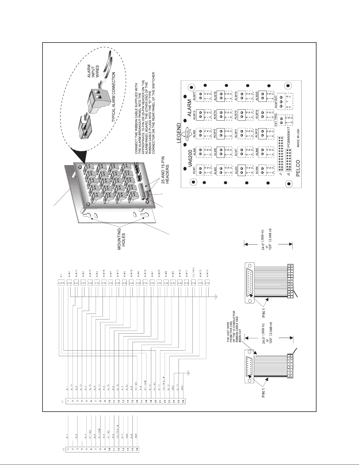
ALARM BREAKOUT PANEL (PCB9000617)
J2
J1
Mounting
PCB Layout
Plate
25-PIN Cable
Keyed connectors
WIRING SCHEMATIC
CABLE ASSEMBLIES
15-PIN Cable
Figure 1. Alarm Breakout Panel Assembly Information–VA6000 Series
Pelco Manual C842M (9/96) 3
Page 6

The table below lists the pin-out relationship between the alarm panel header, J2, and the 15-pin connector on the rear of the VA6000 switcher for 8 input alarms. The pattern serves equally well for VA models
with 4 input alarms: the first 4 Pin Numbers correspond to like numbered ALM numbers, with pins 5-10
unused and pins 11-15 serving the same functions as in the 8 input VA6000 Switcher model.
Alarm Pin-outs 1-8/VA6000
Rear Panel Connector
ALM # 15-Pin Female Conn. on Switcher
J2 Header Pin-out on Alarm Breakout
for VA6000
Pin Numbers
Pin Numbers
11 1
22 3
33 5
44 7
55 9
66 11
77 13
88 15
not used 9 2 (not used)
not used 10 4 (not used)
K1 - NO 11 6
K1 -COM 12 8
K1 - NC 13 10
Ext.Trig. 14 12
Comm 15 14
Figure 2. Installation Configuration and Pin Mapping for 4/8 Alarm Inputs-VA6000 Alarm Breakout Panel
4 Pelco Manual C842M (9/96)
Page 7
The table below lists the pin-out relationship between the alarm panel header, J1, and the 25-pin connector on the rear of the VA6000 switcher for 20 input alarms. The pattern serves equally well for VA
models with 12 input alarms: the first 12 Pin Numbers correspond to like numbered ALM numbers
with pins 13-20 unused and pins 21-25 serving the same functions as in the 20 input VA6000 Switcher
models.
Alarm Pin-outs 1-16/CM8500 Rear Panel-P4
J1 Header Pin-out on Alarm Breakout
for CM8500
ALM # 25-Pin Female Conn. on Switcher
Pin Number
Pin Number
11 1
22 3
33 5
44 7
55 9
66 11
77 13
88 15
99 17
10 10 19
11 11 21
12 12 23
13 13 25
14 14 2
15 15 4
16 16 6
17 17 8
18 18 10
19 19 12
20 20 14
K1 - NO 21 16
K1 -COM 22 18
K1 - NC 23 20
Ext.Trig. 24 22
Comm 25 24
Figure 3. Installation Configuration and Pin Mapping for 12/20 Alarm Inputs-VA6000 Alarm Breakout Panel
Pelco Manual C842M (9/96) 5
Page 8

PCB LAYOUT
Mounting Plate
ALARM BREAKOUT PANEL
(PCB9000582)
WIRING SCHEMATIC
CABLE ASSEMBLY
Figure 4. Alarm Breakout Panel Assembly Information–CM8500 Series
6 Pelco Manual C842M (9/96)
Page 9

The table below lists the pin-out relationship between the alarm panel header, J1, and P4 on the CM8500
for the first 16 alarms. The pattern serves equally well for alarms 17-32: P4 becomes P3 and the listed
alarms go from 17-32 instead of 1-16.
Alarm Pin-outs 1-16/CM8500 Rear Panel-P4
J1 Header Pin-out on Alarm Breakout
for CM8500
ALM # Pin Number
Pin Number
Alarm Com
11 ... 1
22 ... 3
33 ... 5
44 ... 7
55 ... 9
66 ... 11
77 ... 13
88 ... 15
99 ... 17
10 10 ... 19
11 11 ... 21
12 12 ... 23
13 13 ... 25
14 14 ... 27
15 15 ... 29
16 16 ... 31
... 20 2
... 21 4
... 22 6
... 23 8
... 24 10
... 25 12
... 26 14
... 27 16
... 28 18
... 29 20
... 30 22
... 31 24
... 32 26
... 33 28
... 34 30
... 35 32
Figure 5. Installation Configuration and Pin Mapping for the CM8500 Alarm Breakout Panel
Pelco Manual C842M (9/96) 7
Page 10
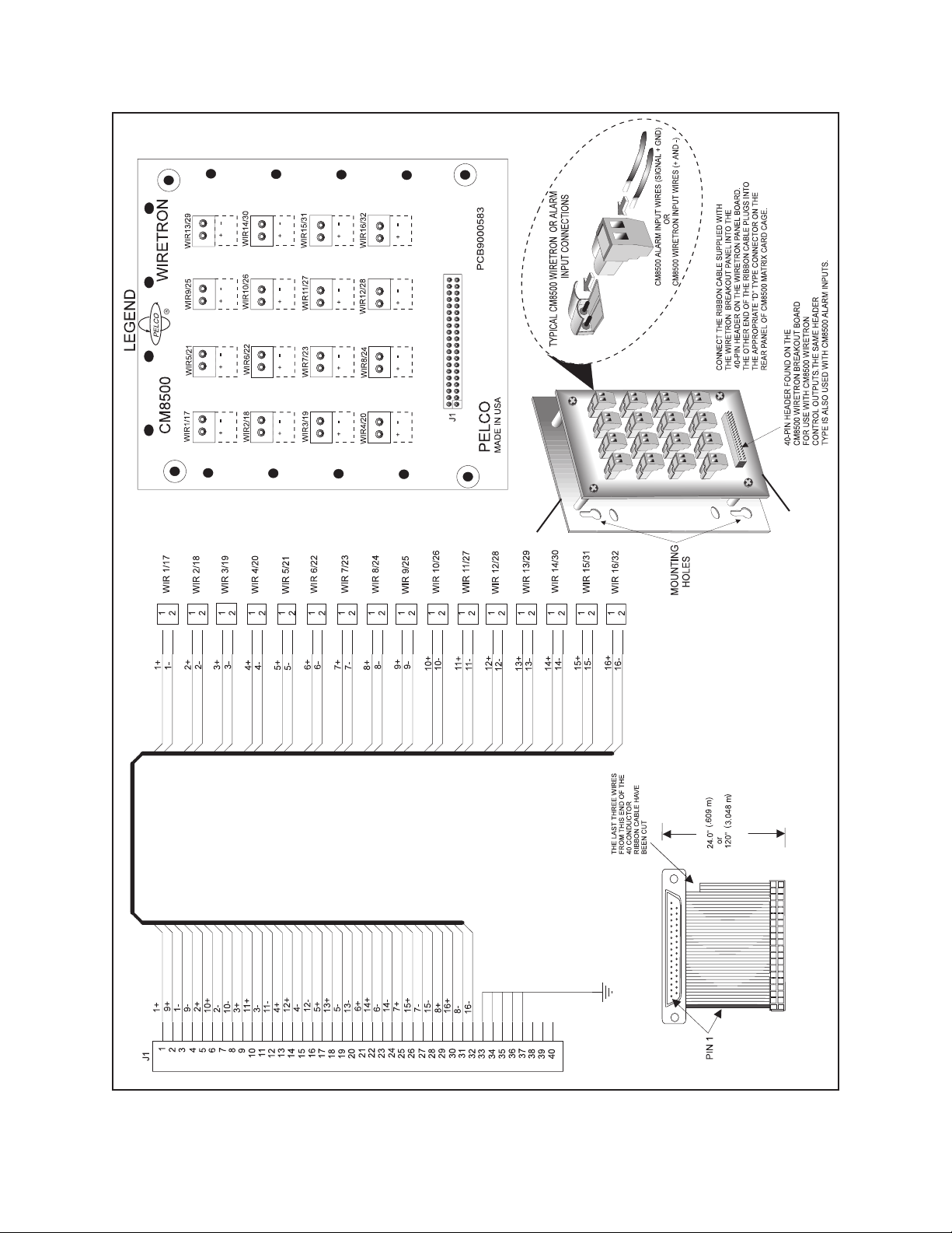
WIRING SCHEMATIC
Mounting Plate
WIRETRON BREAKOUT PANEL
(PCB9000583)
RIBBON CABLE
Figure 6. Wiretron Breakout Panel Assembly Information–CM8500 Series
8 Pelco Manual C842M (9/96)
Page 11

The table below lists the pin-out relationship between the wiretron panel header, J1, and P5 on the
CM8500 for the first 16 wire control positions. The pin mappings serve equally well for wire controls
17-32: P5 becomes P6 and the listed WIR numbers go from 17-32 instead of 1-16.
Wire Control Pin-outs 1-16/CM8500
Rear Panel-P5
WIR # Pin Number
11 ... 1
... 2 3
23 ... 5
... 4 7
35 ... 9
... 6 11
47 ... 13
... 8 15
59 ... 17
... 10 19
611 ... 21
... 12 23
713 ... 25
... 14 27
815 ... 29
... 16 31
920 ... 2
... 21 4
10 22 ... 6
... 23 8
11 24 ... 10
... 25 12
12 26 ... 14
... 27 16
13 28 ... 18
... 29 20
14 30 ... 22
... 318 24
15 32 ... 26
... 33 28
16 34 ... 30
... 35 32
J1 Header Pin-out on Wiretron Breakout
Panel for CM8500
Pin Number
Figure 7. Installation Configuration and Pin Mapping for the CM8500 Wiretron Breakout Panel
Pelco Manual C842M (9/96) 9
Page 12

PCB LAYOUT
Mounting Plate
WIRING SCHEMATIC
Figure 8. Wiretron Breakout Panel Assembly Information–CM8500 Series
RELAY BREAKOUT
PANEL (PCB9000581)
RIBBON CABLE ASSEMBLY
10 Pelco Manual C842M (9/96)
Page 13
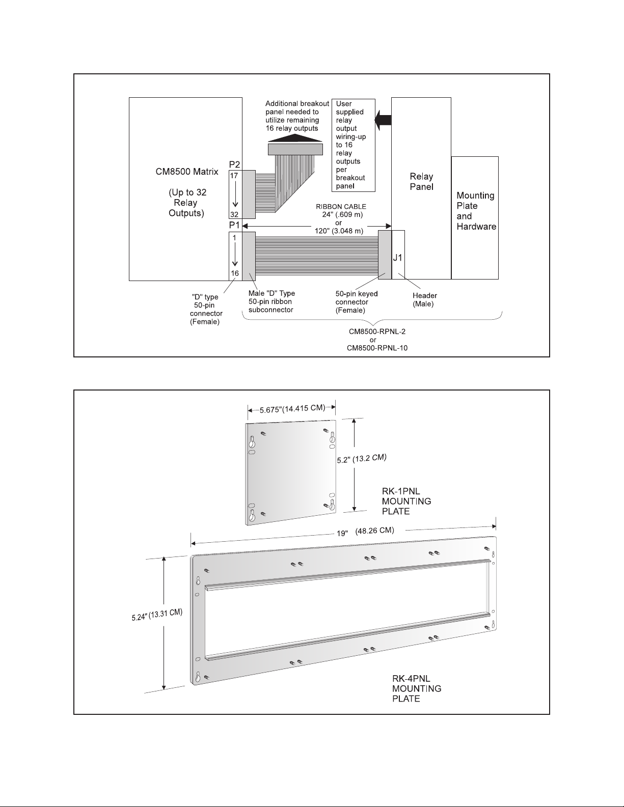
Figure 9. Installation Configuration for the CM8500 Wiretron Breakout Panel
Figure 10. Rack Panel Mounting Plate Dimensions
Pelco Manual C842M (9/96) 11
Page 14
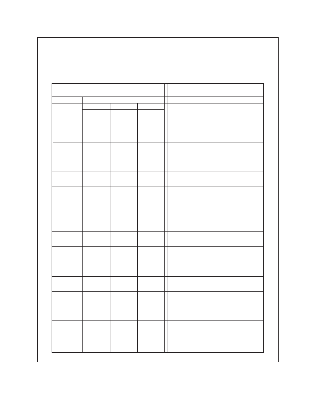
The table below lists the pin-out relationship between the relay panel header, J1, and P1 on the CM8500
for the first 16 relay output positions. The pin mappings serve equally well for relay outputs 17-32: P1
becomes P2 and the listed RELAY numbers go from 17-32 instead of 1-16.
Relay 1-16 Pin-outs CM8500
Rear Panel-P1
J1 Header Pin-out on Relay
Breakout Panel for CM8500
RELAY # Pin Number
NC NO COM
1 ... ... 1
1 ... 2 ... 2
2 ... 5 ... 5
3 ... 8 ... 8
4 ... 11 ... 11
5 ... 14 ... 14
6 ... 17 ... 17
7 ... 20 ... 20
8 ... 23 ... 23
9 ... 26 ... 26
10 ... 29 ... 29
11 ... 32 ... 32
12 ... 35 ... 35
13 ... 38 ... 38
14 ... 41 ... 41
15 ... 44 ... 44
16 ... 47 ... 47
... ... 3 3
4 ... ... 4
... ... 6 6
7 ... ... 7
... ... 9 9
10 ... ... 10
... ... 12 12
13. ... ... 13
... ... 15 15
16 ... ... 16
... ... 18 18
19 ... ... 19
... ... 21 21
22 ... ... 22
... ... 24 24
25 ... ... 25
... ... 27 27
28 ... ... 28
... ... 30 30
31 ... ... 31
... ... 33 33
34 ... ... 34
... ... 36 36
37 ... ... 37
... ... 39 39
40 ... ... 40
... ... 42 42
43 ... ... 43
... ... 45 45
46 ... ... 46
... ... 48 48
Pin Number
Figure 11. Pin Mapping for the CM8500 Relay Breakout Panel
12 Pelco Manual C842M (9/96)
Page 15

5.0 MODELS
VA6008-APNL-2 VA6000 alarm breakout panel
for up to 8 alarm inputs; 2-foot
(.609 m) interconnecting ribbon
cable supplied.
VA6008-APNL-10 Same as VA6008-APNL-2, ex-
cept 10-foot (3.048 m) interconnecting ribbon cable.
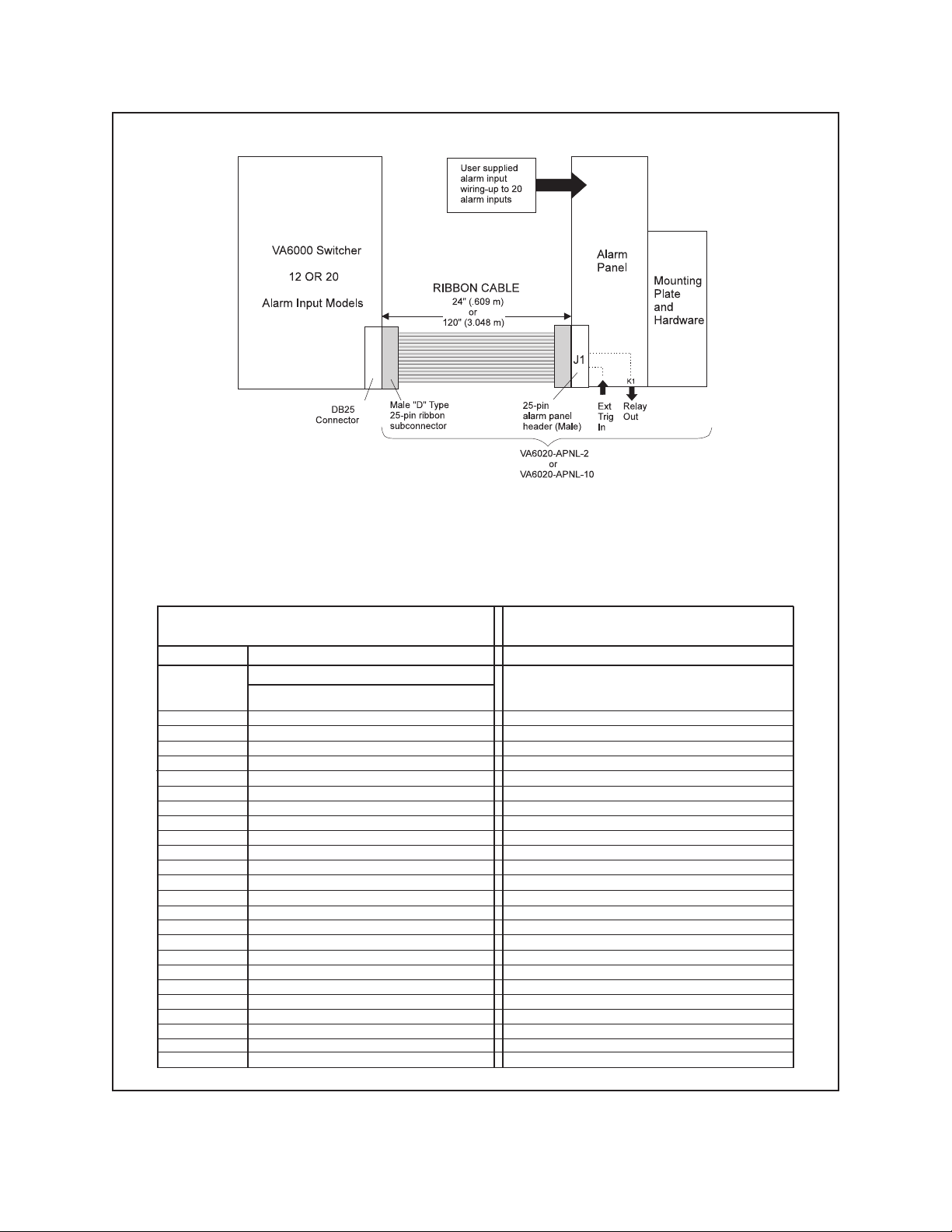
VA6020-APNL-2 VA6000 alarm breakout panel
for up to 20 alarm inputs; 2-foot
(.609 m) interconnecting ribbon
cable supplied.
VA6020-APNL-10 Same as VA6020-APNL-2 ex-
cept 10-foot (3.048 m) interconnecting ribbon cable.
CM8500-WPNL-2 Wiretron breakout panel for up
to 16 outputs/panel; 2-foot (.609
m) inter connecting ribbon cable
supplied.
CM8500-WPNL-10 Same as CM8500-WPNL-2, ex-
cept 10-foot (3.048 m) interconnecting ribbon cable.
CM8500-RPNL-2 Relay breakout panel for up to 16
outputs/panel; 2-foot (.609 m) interconnecting ribbon cable supplied.
CM8500-RPNL-10 Same as CM8500-RPNL-2, ex-
cept 10 foot (3.048 m) interconnecting ribbon cable.
6.0 OPTIONAL ACCESSORIES
CM8500-APNL-2 Alarm breakout panel for up to
16 alarm inputs/panel; 2-foot
(.609 m) interconnecting ribbon
cable supplied.
CM8500-APNL-10 Same as CM8500-APNL-2, ex-
cept 10-foot (3.048 m) interconnecting ribbon cable.
Table I. Alarm Breakout Panel Assembly Part Numbers for VA6000 Series Switchers
# Of Inputs
Cable Length
24 in (.609 m)
4 or 8 Alarm Inputs 12 or 20 Alarm Inputs
VA6008-APNL-2 VA6020-APNL-2
cable
120 in (3.048 m)
VA6008-APNL-10 VA6020-APNL-10
cable
Table II. Breakout Panel Assembly Part Numbers for CM8500 Matrix System
Input Type
Cable Length
Alarm Inputs Wiretron Control Outputs Relay Outputs
RK-1PNL Rack kit for mounting one
breakout panel (see Figure 10).
RK-4PNL Rack kit for mounting up to four
breakout panels (see Figure 10).
24 in (.609 m)
CM8500-APNL-2 CM8500-WPNL-2 CM8500-RPNL-2
cable
120 in (3.048 m)
cable
Pelco Manual C842M (9/96) 13
CM8500-APNL-10 CM8500-WPNL-10 CM8500-RPNL-10
Figure 12. Simplified Part Number Ordering Tables
Page 16

7.0 WARRANTY AND RETURN INFORMATION
WARRANTY
Pelco will repair or replace, without charge, any merchandise proved
defective in material or workmanship for a period of one year after the date
of shipment.
Exceptions to this warranty are as noted below:
• Five years on FT/FR8000 Series fiber optic products.
• Three years on Genex® Series products (multiplexers, server, and
keyboard).
• Three years on Camclosure
CC3701H-2, CC3701H-2X, CC3751H-2, CC3651H-2X, MC3651H-2,
and MC3651H-2X camera models, which have a five-year warranty.
• Two years on standard motorized or fixed focal length lenses.
• Two years on Legacy
DF5/DF8 Series fixed dome products.
• Two years on Spectra
ing when used in continuous motion applications.
• Two years on Esprit
wiper blades).
• Eighteen months on DX Series digital video recorders, NVR300
Series network video recorders, and Endura
network-based video products.
• One year (except video heads) on video cassette recorders (VCRs).
Video heads will be covered for a period of six months.
• Six months on all pan and tilts, scanners or preset lenses used in
continuous motion applications (that is, preset scan, tour and auto scan
modes).
Pelco will warrant all replacement parts and repairs for 90 days from the
date of Pelco shipment. All goods requiring warranty repair shall be sent
freight prepaid to Pelco, Clovis, California. Repairs made necessary by
reason of misuse, alteration, normal wear, or accident are not covered
under this warranty.
Pelco assumes no risk and shall be subject to no liability for damages or
loss resulting from the specific use or application made of the Products.
Pelco’s liability for any claim, whether based on breach of contract,
negligence, infringement of any rights of any party or product liability,
relating to the Products shall not exceed the price paid by the Dealer to
Pelco for such Products. In no event will Pelco be liable for any special,
incidental or consequential damages (including loss of use, loss of profit
and claims of third parties) however caused, whether by the negligence
of Pelco or otherwise.
The above warranty provides the Dealer with specific legal rights. The
Dealer may also have additional rights, which are subject to variation from
state to state.
If a warranty repair is required, the Dealer must contact Pelco at (800) 2899100 or (559) 292-1981 to obtain a Repair Authorization number (RA),
and provide the following information:
1. Model and serial number
2. Date of shipment, P.O. number, Sales Order number, or Pelco invoice
number
3. Details of the defect or problem
If there is a dispute regarding the warranty of a product which does not fall
under the warranty conditions stated above, please include a written
explanation with the product when returned.
Method of return shipment shall be the same or equal to the method by
which the item was received by Pelco.
®
and fixed camera models, except the
®
, CM6700/CM6800/CM9700 Series matrix, and
®
, Esprit®, ExSite™, and PS20 scanners, includ-
®
and WW5700 Series window wiper (excluding
™
Series distributed
RETURNS
In order to expedite parts returned to the factory for repair or credit, please
call the factory at (800) 289-9100 or (559) 292-1981 to obtain an
authorization number (CA number if returned for credit, and RA number
if returned for repair).
All merchandise returned for credit may be subject to a 20% restocking
and refurbishing charge.
Goods returned for repair or credit should be clearly identified with the
assigned CA or RA number and freight should be prepaid. Ship to the
appropriate address below.
If you are located within the continental U.S., Alaska, Hawaii or Puerto
Rico, send goods to:
If you are located outside the continental U.S., Alaska, Hawaii or Puerto
Rico and are instructed to return goods to the USA, you may do one of the
following:
If the goods are to be sent by a COURIER SERVICE, send the goods to:
If the goods are to be sent by a FREIGHT FORWARDER, send the goods
to:
Service Department
Pelco
3500 Pelco Way
Clovis, CA 93612-5699
Pelco
3500 Pelco Way
Clovis, CA 93612-5699 USA
Pelco c/o Expeditors
473 Eccles Avenue
South San Francisco, CA 94080 USA
Phone: 650-737-1700
Fax: 650-737-0933
Pelco
3500 Pelco Way, Clovis, CA 93612-5699 (559)
292-1981 • (800) 289-9100
FAX (800) 289-9150 or (559) 292-3827
International customers call 1-559-292-1981 or
FAX 1-559-348-1120
(Product specifications subject to change
Pelco, the Pelco logo, Camclosure, Esprit, Genex, Legacy, and
Spectra are registered trademarks of Pelco.
Endura and ExSite are trademarks of Pelco.
© Copyright 1996, Pelco. All rights reserved.
without notice.)
C842M
14 Pelco Manual C842M (9/96)
 Loading...