


Model: SLAMU
Installation Guide
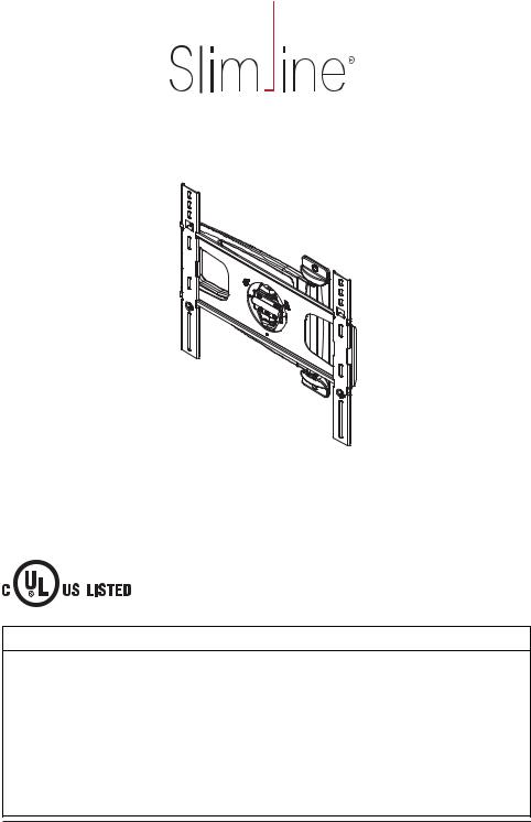
Slimline Ultra-Slim Articulating Mount for 32" to 46"* Ultra Thin Flat Panel Screens
Max UL Load Capacity: 60 lb (27 kg)
 WARNING
This product was designed to be installed on wood stud walls and solid concrete (2000 psi density minimum) or cinder block walls. Before installing make sure the supporting surface will support the combined load of the equipment and hardware. Screws must be tightly secured. Do not overtighten screws or damage can occur or product may fail. Never exceed the Maximum UL Load Capacity. This product is intended for indoor use only. Use of this product outdoors could lead to product failure or personal injury. *Depth of screen must be less than
2" (5 cm). This mount is designed to attach the screen 1.27" (3.2 cm) from the wall. Please refer to manufacturer's installation guide recommendations for required distance from wall to avoid risk of injury or property damage. For support please call customer care at 1-800-865-2112.
ISSUED: 11-30-09 SHEET #: 095-9313-5 10-25-11

Tools Needed for Assembly |
A (1) |
• stud fi nder ("edge to edge" stud fi nder is |
|
recommended) |
|
• drill
• 5/16" (8 mm) bit for concrete and cinder block wall
• 5/32" (4 mm) bit for wood stud wall
• level
C (2)
M5 x 12 mm
E (4)
M6 x 12 mm
G (4)
M8 x 12 mm
M (4)
ID .335" (8.51 mm)
I (4)
M4 x 6 mm 

O (2)
M5 x 25 mm |
B (2) |
F (4) |
|
D (2)
M6 x 25 mm
H (4)
P (2) R (2)
M8 x 25 mm
N (4)
|
S (1) |
ID .344" (8.74 mm) |
T (1) |
J (4) |
|
L (1)
K (1)
2 of 24 |
ISSUED: 11-30-09 SHEET #: 095-9313-5 10-25-11 |
1 Installation to Wood Stud Wall
Use wall mount (A) as a template, make sure it is level, and mark two mounting holes along the center line of the wood stud. Measure 4.8" (122 mm) left or right from stud's center to determine center of screen mounting plate. Drill two 5/32" (4 mm) dia. holes 2.5" (64 mm) deep. Level wall mount (A) and attach to wall with two wood screws (C) into stud center. Use of an edge to edge stud
fi nder is highly recommended. Tighten screws fi rmly, but do not overtighten. Insert two fastener caps
(P) into wall plate mounting holes. NOTE: Be sure arrow of label is facing up when mounting wall arm assembly (A) to wall as shown.
For cable management option, install cable anchor (T) to bottom mounting hole with wood screw (C).
C
A P
 T
T
 WARNING
Do not over tighten screws, or damage may occur.
|
WARNING |
C |
Wood screws must |
center in stud |
|
|
|
A |
STUD |
TOP CUTAWAY VIEW |
3 of 24 |
ISSUED: 11-30-09 SHEET #: 095-9313-5 10-25-11 |
1 |
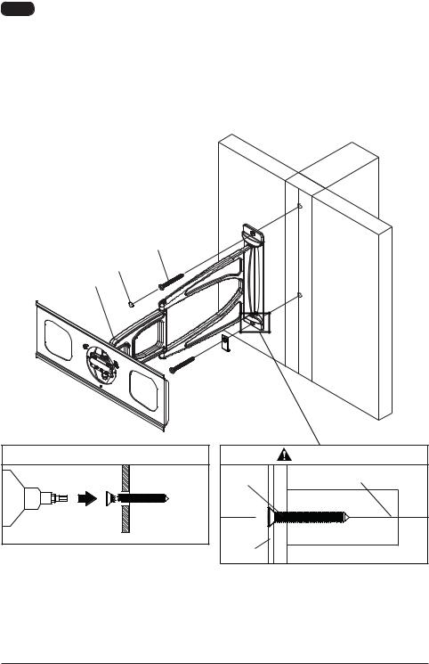
Installing to Solid Concrete or Cinder Block |
Place wall arm (A) on wall as template, level, and mark the center of two mounting holes. Drill two
5/16" dia. holes to a minimum depth of 2.5". Insert anchors (D) into holes fl ush with wall as shown.
Secure wall arm (A) to wall with two wood screws (C) as shown. Insert two fastener caps (P) into wall plate mounting holes.
NOTE: Be sure arrow is pointing up when mounting wall arm assembly (A) to wall as shown in fi gure
1.1. Level, then tighten all fasteners. For cable management option, install cable anchor (T) to bottom mounting hole with wood screw (C).
 WARNING
•When installing Peerless wall mounts on cinder block, verify that you have a minimum of 1-3/8" (35mm) of actual concrete thickness in the hole to be used for the concrete anchors. Do not drill into mortar joints! Be sure to mount in a solid part of the block, generally 1" (25mm) minimum from the side of the block. Cinder block must meet ASTM C-90 specifications. It is suggested that a standard electric drill on slow setting is used to drill the hole instead of a hammer drill to avoid breaking out the back of the hole when entering a void or cavity.
•Always attach concrete anchors directly to load-bearing concrete.
CONCRETE
 CINDER BLOCK
D
C
P
A
T
1 |
D |
|
wall |
Drill holes and insert anchors (D).
2 |
A |
C |
D |
Place plate (A) over anchors (D). Secure with screws (C). Tighten screws.
CUTAWAY VIEW
|
WARNING |
Wall plate |
CORRECT |
plaster/ |
|
dry wall |
concrete |
|
|
Wall plate |
INCORRECT |
plaster/ |
|
dry wall |
concrete |
4 of 24 |
ISSUED: 11-30-09 SHEET #: 095-9313-5 10-25-11 |

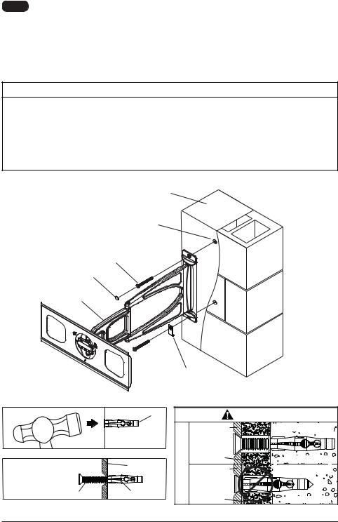
2 |
Installing Brackets |
Align brackets (B) vertically on back of screen. Select screw (E, F, G, H, M or N) that best fi ts your screen. Attach brackets (B) to screen with four selected screws and four washers (I) at the top and bottom of each bracket using allen wrench (L) as shown in detail 1. Spacers (J) may be used to add additional space between the screen and brackets (B) if screen manufacturer requires more than
1.1" (2.8 mm) of ventilation, or if the screen has a bump-out or recessed back as shown in detail 2. Screw must make at least three full turns into the mounting hole and fi t snug into place. Tighten screws fi rmly. Do not overtighten.
Detail 1 |
I |
SCREW |
B |
|
Detail 2 |
|
I |
J |
SCREW |
|
|
|
B |
NOTE: Latch indicates bottom of brackets (B)
5 of 24 |
ISSUED: 11-30-09 SHEET #: 095-9313-5 10-25-11 |
3 Mounting Flat Panel Screen |
3-2 |
NOTE: Wall arm assembly (A) must be in closed position to hang screen.
Rotate safety latch with fl athead screwdriver into unlocked position as shown in detail 3.
Rotate safety latch with fl athead screwdriver and install safety/security screw (O) through safety latch into adapter bracket with phillips screwdriver to lock to adapter plate as shown in detail 4 and detail 5.
SAFETY LATCH
Detail 3
3-1
Hook adapter brackets (B) onto adapter plate of wall arm assembly (A) as shown in fi gure 3.1.

 B
B

 A
A
FIG. 3.1


 A
A
B

Detail 4
SAFETY LATCH
O
Detail 5
 WARNING
Failure to lock bracket (B) with safety/security screw can cause screen to come off mount if hit accidentally.
6 of 24 |
ISSUED: 11-30-09 SHEET #: 095-9313-5 10-25-11 |
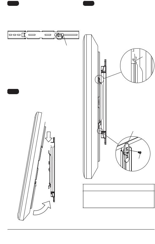
4 Roll Adjustment
Adapter plate may be rolled +/- 5°.
 WARNING
• Do not tighten joint screws. Doing so may cause damage to screws, greatly reducing its holding power.


 JOINT SCREWS
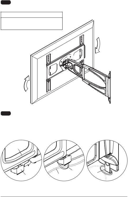
5 Cable Management
Slip cable clip (S) onto bottom of center joint as shown in fi gure 5.1 and secure cables to cable clip using cable tie (R) as shown in fi gure 5.2. Secure cables to cable anchor (T) using cable tie as shown in fi gure 5.3.

 A
A
S |
CABLE |
R |
T |
|
|||
|
|
||
FIG. 5.1 |
FIG. 5.2 |
|
FIG. 5.3 |
Peerless Industries, Inc. |
7 of 24 |
|
ISSUED: 11-30-09 SHEET #: 095-9313-5 10-25-11 |
2300 White Oak Circle |
© 2011, Peerless Industries, Inc. All rights reserved. |
Aurora, Il 60502 |
All other brand and product names are trademarks or |
www.peerlessmounts.com |
registered trademarks of their respective owners. |
Modelo: SLAMU
Guía para la instalación
Soporte articulador Slimline Ultra-Esbelto para pantallas planas Ultra-Delgado de 32" a 46"*
Capacidad de carga máxima de UL: 60 lb (27 kg)
 ADVERTENCIA
Este producto está diseñado para ser instalado en paredes con montantes de madera y en paredes de concreto macizo (de una densidad mínima de 2,000 psi) o en paredes de hormigón de escorias.
Antes de instalarlo, asegúrese de que la superfi cie de apoyo sostendrá la carga combinada del equipo y los fi jadores. Los tornillos se tienen que fi jar fi rmemente. No apriete los tornillos en exceso o se pueden dañar y el producto podría fallar. Nunca exceda la Capacidad Máxima de Carga de UL.
Este producto está diseñado para uso en interiores solamente. Utilizar este producto en exteriores podría causar fallas del producto o lesiones a individuos. *La profundidad de la pantalla tiene que ser menos de 2" (5 cm). Este soporte está diseñado para sostener la pantalla a 1.27" (3.2 cm) de la pared. Por favor, repase las recomendaciones del manual de instalación del fabricante con respecto a la distancia necesaria de la pared para evitar el riesgo de sufrir lesiones o causar daños a la propiedad. Si necesita ayuda, por favor, llame a Servicio al Cliente de Peerless al 1-800-865-2112.
PUBLICADO: 01-05-10 HOJA N.O: 095-9313-5 10-25-11
 Loading...