


PRG-1W
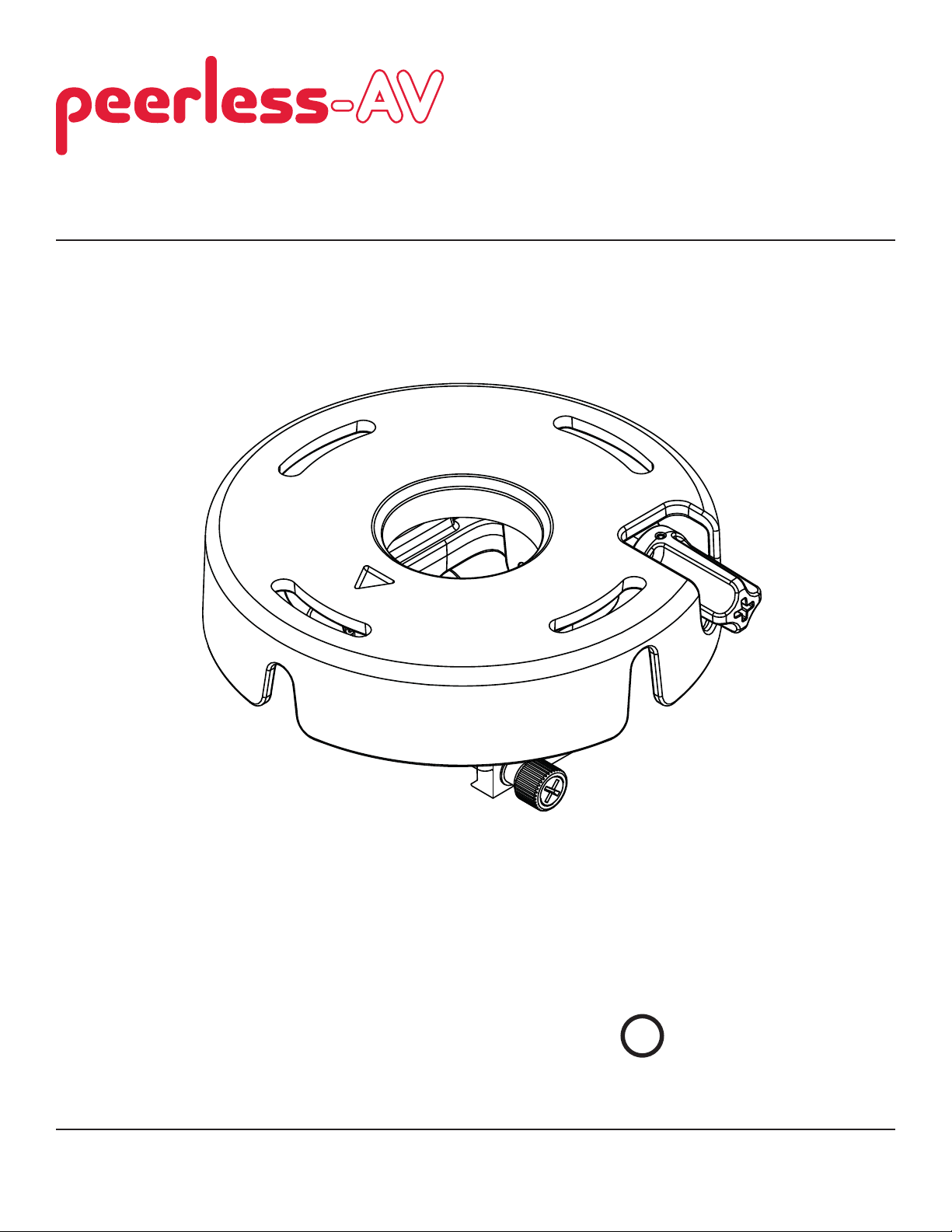
Installation and Assembly Manual:
PRG Precision Gear Projector Mount
Models: PRG-1, PRG-1S, PRG-1W
Features:
• ImageLockTM alignment prevents picture sag or drift
• Exclusive aluminum track quick release
2300 White Oak Circle • Aurora, Il 60502 • (800) 865-2112 • Fax: (800)359-6500 • www.peerlessmounts.com
This product is intended for use with UL
U
©
Listed products and must be installed by a
L
USC
qualifi ed professional installer.
Maximum UL Load Capacity:
50 lb (22.7 kg)
ISSUED: 08-15-07 SHEET #: 055-9491-7 06-11-11

NOTE: Read entire instruction sheet before you start installation and assembly.
WARNING
• Do not begin to install your Peerless product until you have read and understood the instructions and warnings
contained in this Installation Sheet. If you have any questions regarding any of the instructions or warnings, please
call Peerless customer care at 1-800-865-2112.
• This product should only be installed by someone of good mechanical aptitude, has experience with basic building
construction, and fully understands these instructions.
• Make sure that the supporting surface will safely support the combined load of the equipment and all attached hardware and components.
• Never exceed the Maximum UL Load Capacity. See page 1.
• If mounting to wood joist ceilings, make sure that mounting screws are anchored into the center of the joist. Use of
an "edge to edge" stud fi nder is highly recommended.
• Always use an assistant or mechanical lifting equipment to safely lift and position equipment.
• Tighten screws fi rmly, but do not overtighten. Overtightening can damage the items, greatly reducing their holding
power.
• This product is intended for indoor use only. Use of this product outdoors could lead to product failure and personal
injury.
• This product was designed and intended to be mounted to the following supporting surfaces checked below with
the hardware included in this product as specifi ed in the installation sheet. To mount this product to an alternative
supporting surface, contact Peerless customer care at 1 800 865-2112.
• This product was designed to be installed on the following ceiling construction only;
CEILING CONSTRUCTION ADDITIONAL HARDWARE REQUIRED
x Wood Stud None
x Wood Joist None
x Solid Concrete None
Brick Contact Customer Service (Not Evaluated by UL)
Other or unsure? Contact Customer Service (Not Evaluated by UL)
Tools Needed for Assembly
• stud fi nder ("edge to edge" stud fi nder is recommended)
• phillips screwdriver
• drill
• 5/16" bit for concrete surface
• 5/32" bit for wood studs
• level
Table of Contents
Parts List............................................................................................................................................................................ 3
Installation to Extension Columns / Ceiling Plate .............................................................................................................. 4
Installation to Wood Joist Ceilings .....................................................................................................................................5
Installation to Concrete Ceilings ........................................................................................................................................ 6
Installation to Threaded Rods ............................................................................................................................................ 7
Attaching Adapter Plate to Projector.................................................................................................................................. 8
Attaching Adapter Plate to Projector Mount....................................................................................................................... 9
Cable Management .........................................................................................................................................................10
Projector Alignment ......................................................................................................................................................... 11
Accessories ............................................................................................................................................................... 12, 13
ISSUED: 08-15-07 SHEET #: 055-9491-7 06-11-11
Visit the Peerless Web Site at www.peerlessmounts.com
2 of 13
For customer care call 1-800-865-2112 or 708-865-8870.
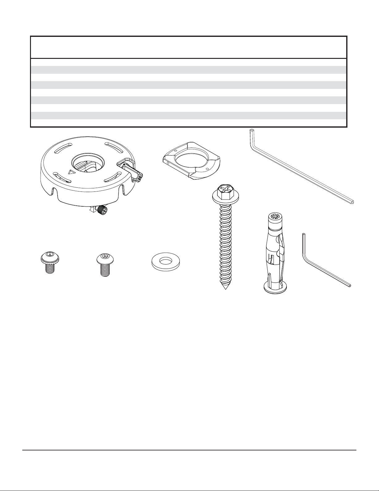
Before you start check the parts list to insure all of the parts shown are included.
Parts List
Description Qty. Part # Part # Part #
projector mount assembly 1 055-1968 055-4968 055-2968
A
4 mm security allen wrench 1 560-9646 560-9646 560-9646
B
#10-32 x 3/8" serrated washer head socket pin screw 2 520-1151 520-2151 520-2151
C
#10-32 x 1/4" socket pin screw 1 520-1196 520-2196 520-2196
D
flat washer 2 540-1078 540-1078 540-1078
E
#14 x 2-1/2 phillips hex head wood screw 2 5S1-015-C03 5S1-015-C04 5S1-015-C04
F
concrete anchor 2 590-0320 590-0320 590-0320
G
2 mm security allen wrench 1 560-1097 560-1097 560-1097
H
I
connection block
A
PRG-1 PRG-1S PRG-1W
1
580-1065 580-4065 580-4065
B
I
C
NOTE: Actual parts may appear slightly different than illustrated.
D
E
F
G
H
Visit the Peerless Web Site at www.peerlessmounts.com
3 of 13
ISSUED: 08-15-07 SHEET #: 055-9491-7 06-11-11
For customer care call 1-800-865-2112 or 708-865-8870.
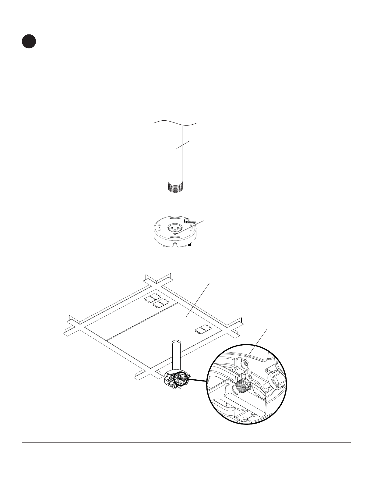
Installation to Extension Column / Ceiling Plate
NOTE: Refer to accompanying instructions with ceiling plates (sold separately) for installing these models to
1
ceiling.
Screw projector mount assembly (A) onto extension column as shown in fi gure 1.1. Tighten swivel stop screw
against extension column, fl ush mount tube or reducer using 4mm security allen wrench (B) as shown in fi gure
1.2.
NOTE: Swivel stop screw is used to jam against threads of extension column, fl ush mount tube or reducer to
prevent any excess movement of projector mount assembly (A). Do not overtighten screw; overtightening screw
will damage threads making it diffi cult to separate products.
Skip to step 5.
1-1/2" EXTENSION COLUMN
(SOLD SEPARATELY)
(UL LISTED EXT OR AEC SERIES)
A
ARROW
INDICATES FRONT
OF MOUNT
fi g. 1.1
CMJ 455
(SOLD SEPARATELY)
SWIVEL STOP SCREW
Visit the Peerless Web Site at www.peerlessmounts.com
fi g. 1.2
4 of 13
ISSUED: 08-15-07 SHEET #: 055-9491-7 06-11-11
For customer care call 1-800-865-2112 or 708-865-8870.
 Loading...