

Page 1
Installation and Assembly:
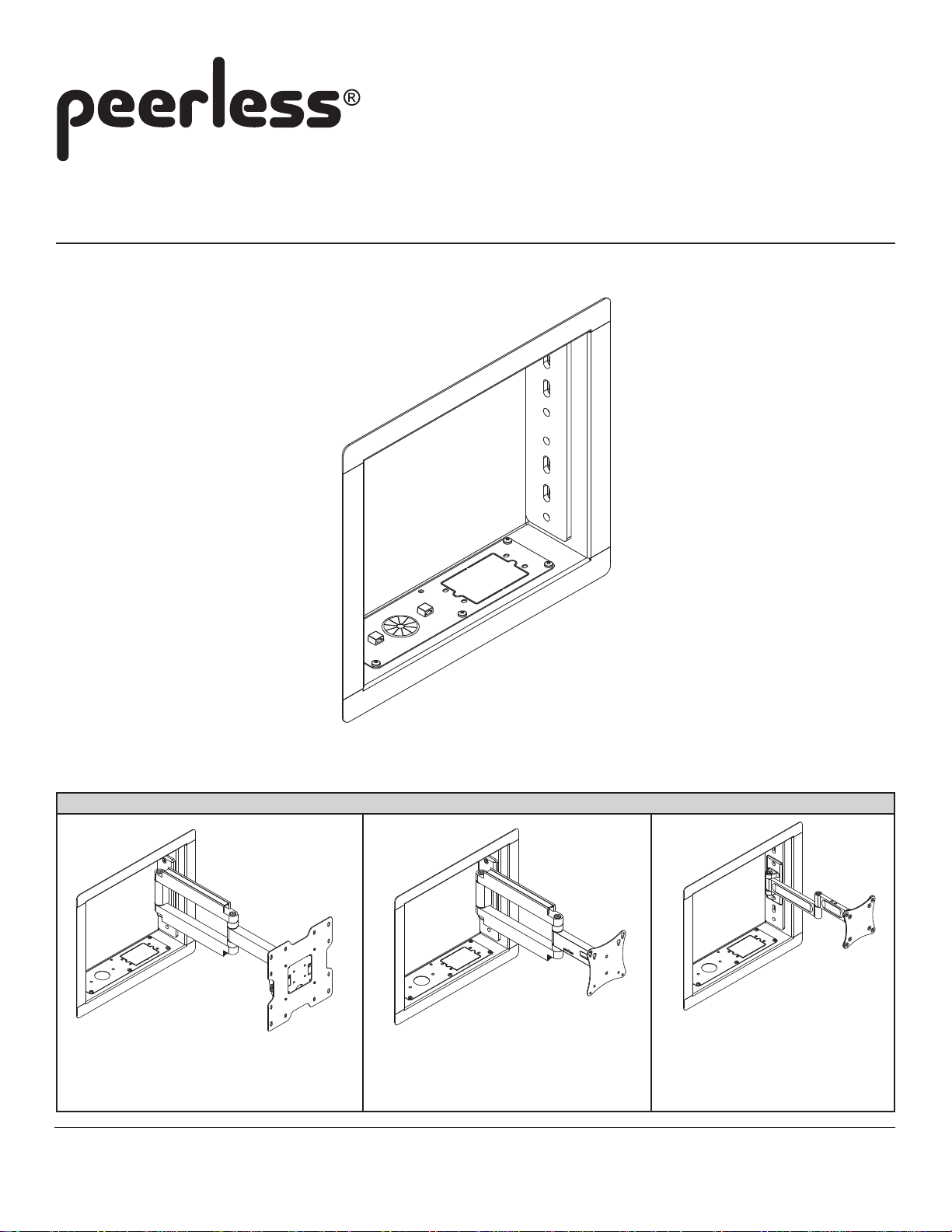
In-wall Mount for up to 40" Flat Panel Screens
Models: IB40, IB40-S, IB40-W
IN-WALL MOUNT USED WITH ARTICULATING ARM MOUNTS (NOT INCLUDED)
MODELS: SA740P, SA740P-S
MAX LOAD CAPACITY:
80 LB (36.3 KG)
Visit the Peerless Web Site at www.peerlessmounts.com
MODELS: SA730P, SA730P-S
MAX LOAD CAPACITY:
25 LB (11.3 KG)
1 of 6
For customer care call 1-800-865-2112 or 708-865-8870.
MODEL: LCS-KLA
MAX LOAD CAPACITY:
25 LB (11.3 KG)
ISSUED: 12-04-07 SHEET #: 095-9281-1
Page 2
Note: Read entire instruction sheet before you start installation and assembly.
WARNING
• Do not begin to install your Peerless product until you have read and understood the instructions and warnings
contained in this Installation Sheet. If you have any questions regarding any of the instructions or warnings, please
call Peerless customer care at 1-800-865-2112.
• This product should only be installed by someone of good mechanical aptitude, has experience with basic building
construction, and fully understands these instructions.
• Make sure that the supporting surface will safely support the combined load of the equipment and all attached hardware and components.
• Never exceed the Maximum Load Capacity.
• If mounting to wood wall studs, make sure that mounting screws are anchored into the center of the studs. Use of an
"edge to edge" stud finder is highly recommended.
• Always use an assistant or mechanical lifting equipment to safely lift and position equipment.
• Tighten screws firmly, but do not overtighten. Overtightening can damage the items, greatly reducing their holding
power.
• This product was designed and intended to be mounted to the following supporting surfaces checked below with the
hardware included in this product as specified in the installation sheet. To mount this product to an alternative supporting surface, contact Peerless customer care at 1 800 865-2112.
• This product was designed to be installed on the following wall construction only;
WALL CONSTRUCTION ADDITIONAL HARDWARE REQUIRED
x Wood Stud None
Wood Beam Contact Customer Service
Solid Concrete Contact Customer Service
Cinder Block Contact Customer Service
Metal Stud Contact Customer Service
Brick Contact Customer Service
Other or unsure? Contact Customer Service
Tools Needed for Assembly
• stud finder ("edge to edge" stud finder is recommended)
• phillips screwdriver
• drill
• 5/32" and 1/8" bit for wood stud wall
• level
Table of Contents
Parts List .............................................................................................................................................................................. 3
Installation to Wood Stud Wall ............................................................................................................................................. 4
Installing Articulating Arm to In-wall Box ............................................................................................................................... 5
Attaching Screen .................................................................................................................................................................. 5
Cable Management ............................................................................................................................................................... 6
ISSUED: 12-04-07 SHEET #: 095-9281-1
Visit the Peerless Web Site at www.peerlessmounts.com
2 of 6
For customer care call 1-800-865-2112 or 708-865-8870.
Page 3

Before you begin, make sure all parts shown are included with your product.
IB40 IB40-S IB40-W
Description Qty. Part # Part # Part #
A
in-wall box 1 095-P1536 095-C4536 095-2536
B
#10 x 1.5" wood screw 2 500-2002 500-2002 500-2002
C
mounting cover plate 2 095-P1533 095-C4533 095-2533
D
ribbed rivet 4 590-1296 590-1296 590-1296
E
cable bushing 2 590-1295 590-1295 590-1295
F
cable management clips 4 590-1166 590-1166 590-1166
G
plastic finishing cap 2 590-1123 590-1123 590-1123
H
cable tie 4 590-1168 590-1168 590-1168
Parts List
Parts may appear slightly different than illustrated.
A
Visit the Peerless Web Site at www.peerlessmounts.com
E
F
B
G
3 of 6
C
D
H
ISSUED: 12-04-07 SHEET #: 095-9281-1
For customer care call 1-800-865-2112 or 708-865-8870.
Page 4

Installation to Wood Stud Wall
WARNING
• Installer must verify that the supporting surface will safely support the combined load of the equipment and all attached
hardware and components.
• Tighten wood screws so that wall plate is firmly attached, but do not overtighten. Overtightening can damage the
screws, greatly reducing their holding power.
• Never tighten in excess of 80 in. • lb (9 N.M.).
• Make sure that mounting screws are anchored into the center of the stud. The use of an "edge to edge" stud finder is
highly recommended.
• Hardware provided is for attachment of mount through standard thickness drywall or plaster into wood studs. Installers
are responsible to provide hardware for other types of mounting situations.
In-wall box (A) can be installed between two studs 16" off
1
center. Use a stud finder to locate the edges of the stud. Use
of an edge-to-edge stud finder is highly recommended. Based
on its edges, draw two vertical lines down the inside edges of
stud’s. Mark desired center of in-wall box. Draw a horizontal
line above desired center of in-wall box 6-1/8" (150 mm). Draw
a second horizontal line 12-1/4" (311 mm) below this line to
outline wall opening between inside edges of studs. Remove
drywall inside cut outline.
Note: In-wall box can be flipped for left of right side mount
orientation as shown in figure 1.2.
Insert in-wall box (A) into cut-out until in-wall box flange is
flush with drywall.
Level in-wall box, and drill two mounting holes 1/8" (3 mm)
dia. holes 1-1/2" (38 mm) deep using mounting holes on tabs
of in-wall box. Make sure in-wall box is level, secure it using
two #10 x 1-1/2" wood screws (B) as shown in figure 1.3.
Attach two mounting cover plates (C) to in-wall box (A) using
four ribbed rivets (D) as shown in figure 1.4.
STUDS
14.5"
(368 mm)
6-1/8"
(150 mm)
CENTER OF
IN-WALL BOX
fig. 1.1
TOP LINE OF CUT
OUTLINE
12-1/4"
(311 mm)
A
A
FLANGE
LEFT
ORIENTATION
A
FLANGE
RIGHT
ORIENTATION
fig. 1.2
Visit the Peerless Web Site at www.peerlessmounts.com
4 of 6
TABS
C
B
fig. 1.3
ISSUED: 12-04-07 SHEET #: 095-9281-1
For customer care call 1-800-865-2112 or 708-865-8870.
D
fig. 1.4
Page 5

Installing Articulating Arm to In-wall Box
In-wall box can support Peerless articulating arm models
SA740P, SA740P-S, SA730P, SA730P-S and LCS-KLA (not included).
Choose hole pattern on interior mounting plate of in-wall box (A) which align with hole pattern on the wall plate of
2
articulating arm. Mounting hole alignments may be selected for different height installations.
Note: Consider position of screen center or routing of cables before securing arm to in-wall box.
Drill two 5/32" (4 mm) holes 2.5" (65 mm) deep using interior mounting plate holes of in-wall box (A) as a guide.
Attach arm to in-wall box using two #14 x 2-1/2" wood screws (included with articulating arm).
WALL PLATE OF
ARTICULATING ARM
#14 X 2-1/2" WOOD
SCREWS (INCLUDED WITH
ARTICULATING ARM)
INTERIOR MOUNTING
PLATE OF IN-WALL BOX
(A)
MODELS: SA740P, SA740P-S
MODEL SA740P ARTICULATING ARM SHOWN
ARTICULATING ARM MODELS (NOT INCLUDED)
MODELS: SA730P, SA730P-S MODEL: LCS-KLA
(NOT INCLUDED)
Installing Screen to Arm
Refer to instruction included with articulating arm (sold separately) for installation of screen.
3
CAUTION
• Do not exceed the Maximum Load Capacity indicated
on articulating arm instruction.
Visit the Peerless Web Site at www.peerlessmounts.com
5 of 6
ISSUED: 12-04-07 SHEET #: 095-9281-1
For customer care call 1-800-865-2112 or 708-865-8870.
Page 6

Cable Management
For optional installation of electrical gang box, access plates located on the bottom or top of in-wall box can be
4
temporarily removed to install electrical gang box as shown in figure 4.1.
MODEL SA740P ARTICULATING ARM SHOWN (NOT INCLUDED)
ACCESS
PLATE
4-1
fig. 4.2
SCREEN NOT SHOWN
FOR CLARITY
fig. 4.1
Insert up to four cable management clips (F) into the desired positions in the in-wall box as shown in figure 4.2
for routing cables. Refer to instruction included with articulating arm for cable management with arm.
Insert cable bushing (E) into top or bottom hole of in-wall box for routing cables through in-wall box. Plastic
finishing caps (G) can be used in holes where cables are not being routed.
NOTE: Make sure cables have enough slack to allow full movement of the arm.
Use cable ties (H) to secure cables to cable management clips as shown in figure 4.3.
fig. 4.3
CABLES
F
E or G
SCREEN NOT SHOWN FOR CLARITY
Visit the Peerless Web Site at www.peerlessmounts.com
H
6 of 6
For customer care call 1-800-865-2112 or 708-865-8870.
All other brand and product names are trademarks or registered trademarks of their respective owners.
ISSUED: 12-04-07 SHEET #: 095-9281-1
© 2007, Peerless Industries, Inc. All rights reserved.
 Loading...