


VYPYR® PRO
Modeling Amplifier
Operating
Manual
www.peavey.com

FCC Compliancy Statement
This device complies with Part 15 of the FCC rules. Operation is subject to the following two conditions: (1) this device may not cause harmful interference, and (2) this device must accept any interference received, that may cause undesired operation.
Warning: Changes or modifications to the equipment not approved by Peavey Electronics Corp. can void the user’s authority to use the equipment.
Note - This equipment has been tested and found to comply with the limits for a Class B digital device, pursuant to Part 15 of the FCC Rules. These limits are designed to provide reasonable protection against harmful interference in a residential installation. This equipment generates, uses and can radiate radio frequency energy and, if not installed and used in accordance with the instructions, may cause harmful interference to radio communications. However, there is no guarantee that interference will not occur in a particular installation. If this equipment does cause harmful interference to radio or television reception, which can be determined by turning the equipment off and on, the user is encouraged to try and correct the interference by one or more of the following measures.
•Reorient or relocate the receiving antenna.
•Increase the separation between the equipment and receiver.
•Connect the equipment into an outlet on a circuit different from that to which the receiver is connected.
•Consult the dealer or an experienced radio/TV technician for help.
Vypyr® Pro 100
In order for the above two models to meet FCC/ICES requirements, a Steward 28A0592-0A2 ferrite core (or equivalent) must be placed on the USB cable where it exists/connects to the amplifier.
Peavey Electronics Corporation • 5022 Hartley Peavey Drive • Meridian, MS • 39305 (601) 483-5365 • FAX (601) 486-1278 • www.peavey.com
Features and specifications are subject to change without notice.
© 2015 EX000190

ENGLISH
Vypyr® Pro
Modeling Amplifier
Congratulations on the purchase of the most advanced modeling amplifier to date! Peavey® introduces its newest member of the VYPYR Series, the VYPYR PRO 100. As the name implies, the VYPYR PRO is an amp featuring professional-grade tone and features, in a unique and intuitive layout. Because of the advanced dual processor design, the VYPYR Pro can run up to four amplifier models in parallel. Using the VYPYR Pro’s unique architecture, the VYPYR is capable of designing a variety of signal path combinations. Four module bays each with their own distinct LCD can be assigned to an amplifier, effect, stomp box, or in the first position an instrument model.
The modules can be assigned in any order, allowing the user the ability to create the exact rig they desire, even if they desire to run two or up to four amplifiers in parallel. With up to 5 parameters to precisely control effects, multiple delay types and advanced features such as MSDI (microphone simulated direct interface), direct output, effects loop, and MIDI control allow the professional player to create the rig of their dreams inside a single combo amplifier.
The VYPYR Pro continues the tradition of appropriate technology using 4 stages of patented TransTube® analog gain to create the most realistic tube sounding distortion in any modeling amplifier. By using analog distortion, the VYPYR Pro’s digital processor has the amazing ability to offer almost limitless combinations of additional stompboxes, “rack” effects, amplifiers and now even instrument models. The result is an overall better and cleaner tone.
Recording is a mainstay of the VYPYR Pro design. With the most advanced USB audio system in any VYPYR, the Pro was designed from the beginning for home recording. The VYPYR Pro also features an analog speaker and microphone simulated direct out for recording as well.
With 500 presets available and dozens of different models of effects, reverbs, delays and amplifiers, the VYPYR Pro is the most innovative and advanced modeling amplifier on the planet. Designed for the working musician by the musicians at Peavey Electronics, it is perhaps the most versatile amp ever created.
The perfect companion for the VYPYR Pro, Peavey’s updated Sanpera® Pro Footcontroller unlocks all the power of the VYPYR Pro. The Sanpera Pro’s dual expression pedals can be assigned to the default setting (volume on left, wah on right), and to 3 different stompbox or effects parameters! The Sanpera Pro’s expression pedals are also range definable. The footcontroller also features a boost switch, tap tempo, a chromatic tuner, and looper controls that allow users to generate multi-track loops.
AT-200™ integration is a key part of the VYPYR Pro design. The MIDI output allows the VYPYR Pro to communicate with Peavey’s revolutionary AT-200 guitar in order to change presets inside the guitar with one simple VYPYR Pro button press (requires an AT-200 guitar loaded with one of the optional feature packs, available at www.autotuneforguitar.com)
KEY FEATURES:
•Dozens and dozens of different amp, effect, stompbox and instrument models
•Advanced WYSIWYG interface - What you see is what you get!
•Four selectable model bays with an LCD for each
•Multiple delay and reverb types
•Patented Analog TransTube preamps
•100 Watts
•Custom voiced 12” speaker specifically designed for modeling
•500 user assignable presets
•Real time control over Delay, Reverb and real time model parameter control
•3 adjustable noise gates
•MIDI output for changing presets on an external MIDI device, including the Peavey AT-200 guitar
•Buffered Effects Loop
•Power Sponge output power adjustment
•MSDI™ Output with XLR and ground lift switch
•USB Interface for recording, editing presets and updating firmware
•Speaker defeat switch
•Studio-quality Headphone output
•On board chromatic tuner
•On board over-dubbing looper with optional Sanpera footswitch
VENTILATION: For proper ventilation, allow 24" clearance from nearest combustible surface.
VYPYR® PRO Quick Start
|
|
|
|
6 |
|
5 |
|
|
|
|
|
|
|
model 1 |
model 2 |
model 3 |
model 4 |
pre P1 |
low P2 |
mid P3 |
high P4 |
post P5 |
master |
User Presets |
|
|
|
input |
|
|
|
|
|
|
|
|
5 6 7 8 |
|
on |
on |
|
|
|
|
|
|
|
|
|
|
|
||||
|
|
|
|
|
|
|
|
4 |
9 |
|
|
|
|
|
|
|
|
|
|
|
|
3 |
10 |
|
|
|
|
|
|
|
|
|
|
|
|
2 |
11 |
|
|
|
|
|
|
mode |
tap/ |
del/rev |
|
|
|
1 |
12 |
|
(outer) bank |
|
|
|
|
|
|
|
0 |
13 |
aux in phones |
|
|
||||
VYPYR |
|
select |
cancel |
edit |
|
|
|
|
|
(inner) preset |
standby |
power |
|
|
|
|
|
|
|
|
|
|
|
select |
|||
® |
|
|
|
shift |
level |
feedback |
room size |
level |
|
|
push to |
|
|
PRO-100 |
|
|
|
|
|
MAIN menu |
|
|
|||||
|
|
|
|
|
|
|
|
|
|
|
HOLD for |
|
|
|
|
push to edit |
HOLD |
HOLD |
delay |
|
|
reverb |
|
|
|
|
|
|
|
|
for tuner |
for adv. edit |
|
|
|
|
|
|
|
|
|
|
|
4 |
|
|
|
|
|
|
|
|
|
|
|
3 |
|
|
|
|
|
|
|
|
|
|
2 |
1 |
|
A. Plug and Play
•Turn power/standby switches to “On” position. The standby switch is included so that you can play and record with the power amp switched off.
•Plug in instrument.
•Selecting Presets–Use knob on far right of panel.
•Use outer bank wheel (1) to scroll through preset banks. Each bank contains four presets. •Use inner knob (2) to find a preset. Press inner knob to select the preset.
B. Adjusting Presets
•Model Select
•Push model select button (3).
•Scroll(4) through Model Types (i.e. Stomp Box, instrument, effect or amp) and press knob (4).
•Select modes for up to 4 models.
•Scroll through amp models, for example, and press the knob to select.
•With the model selected, the parameter knobs (5) will illuminate to display that model’s current settings.
•Adjust Model Parameters
•Press model you want to edit.
•The parameter knobs will illuminate to reflect that model’s settings.
•Edit chosen model using the parameter knobs.
•The Vypyr Pro will remember your changes even if you change models until you save the preset.
•Delay/Reverb Quick Edit Menu
•Tap the Delay/Reverb Edit button (6)
•The main parameter knobs (5) now are controlling the parameters listed below the knobs which include Delay Time Shift, Delay Level, Delay Feedback, Reverb Room Size and Reverb Level.
NOTE: The Deep Edit Menu contains much more detailed tone shaping tools. In this menu you will find submenus for Delay, Reverb, Input and Output settings. This menu is described in detail later in
this owner’s manual.
C. VYPYR® Main Edit Menu
•To enter main menu, press inner preset button (2)
•Use either the outer bank wheel (1) or inner knob (2) to scroll through the following functions: Load Preset; Save Preset; Rename Preset; Rename Bank; Default Pedals; Assign Pedals; Enable/Disable Midi Out; Midi Out Channel; Restore Preset; Factory Reset; Disable/ Enable Demo; Delay Trails On/Off; Reverb Trails On/Off; Show Version; Update Software; Input Sensitivity; Exit Menu
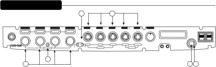
Front Panel
1 |
|
2 |
|
6 |
|
9 |
|
|
10 |
|
13 |
|
15 |
16 |
model 1 |
model 2 |
model 3 |
model 4 |
pre P1 |
low P2 |
mid P3 |
high P4 |
post P5 |
master |
User Presets |
|
|
|
|
input |
|
|
|
|
|
|
|
|
5 6 7 8 |
|
on |
on |
||
|
|
|
|
|
|
|
|
|
|
|
||||
|
|
|
|
|
|
|
|
4 |
9 |
|
|
|
|
|
|
|
|
|
|
|
|
|
3 |
10 |
|
|
|
|
|
|
|
|
|
|
|
|
|
2 |
11 |
|
|
|
|
|
|
|
mode |
tap/ |
del/rev |
|
|
|
1 |
12 |
|
|
(outer) bank |
|
|
|
|
|
|
|
0 |
13 |
aux in |
phones |
|
|
||||
VYPYR |
|
select |
cancel |
edit |
|
|
|
|
|
(inner) preset |
standby |
power |
||
|
|
|
|
|
|
|
|
|
|
|
select |
|||
® |
|
|
|
shift |
level |
feedback |
room size |
level |
|
|
|
push to |
|
|
PRO-100 |
|
|
|
|
|
|
MAIN menu |
|
|
|||||
|
|
|
|
|
|
|
|
|
|
|
|
HOLD for |
|
|
|
|
push to edit |
HOLD |
HOLD |
delay |
|
|
reverb |
|
|
|
|
|
|
|
|
|
for tuner |
for adv. edit |
|
|
|
|
|
|
|
|
|
|
|
|
3 |
|
|
|
|
|
|
|
|
|
|
|
|
4 |
|
|
5 |
|
7 |
|
|
8 |
|
11 |
12 |
|
14 |
|
1Instrument Input
Plug in your instrument here.
2Model Bay Displays
In “Mode Select” mode displays the available model types (Instrument {model bay 1 only}, Amp, Stomp Box and Effects). In normal mode displays the selected models.
3Mode Select Button
Allows the user to switch into Mode Select mode. Holding the Mode Select Button down for 2 seconds changes the Model Select Knobs to Signal Chain Select Mode. In this mode, you can change the order that the models are in, simply by turning the knobs. This is particularly handy when you have forgotten to add a certain model in model bay 1. With Signal Chain Select Mode, you would then move the other 3 models to the right, leaving Model Bay 1 empty and ready for you to add the model you wish to add.
4Model Select Knobs
Allows user to scroll through Modules and Modes.
5Tap Tempo Control/Tuner Selector/Cancel
Tapping this button sets the delay time for the Delay effect. Holding this button down activates the tuner function. In most instances, this button can be used to cancel out of a menu.
6Delay/Reverb Edit Button
Tapping this button once activates the Delay/Reverb Quick Edit Menu. Pressing and holding this button activates the Deep Edit Menu, which is described in detail later in this owner’s manual.
7Delay Parameter Adjustment Knobs
When in Delay Edit Mode, these knobs adjust Shift, Delay Level and Feedback.
8Reverb Parameter Adjustment Knobs
When in Reverb Edit Mode, these knobs adjust Room Size and Level.
9Parameter Adjustment Knobs
These knobs adjust model parameters. Amp parameters are listed because they are the same on each amp. Other model parameters are shown on the screen as you edit.

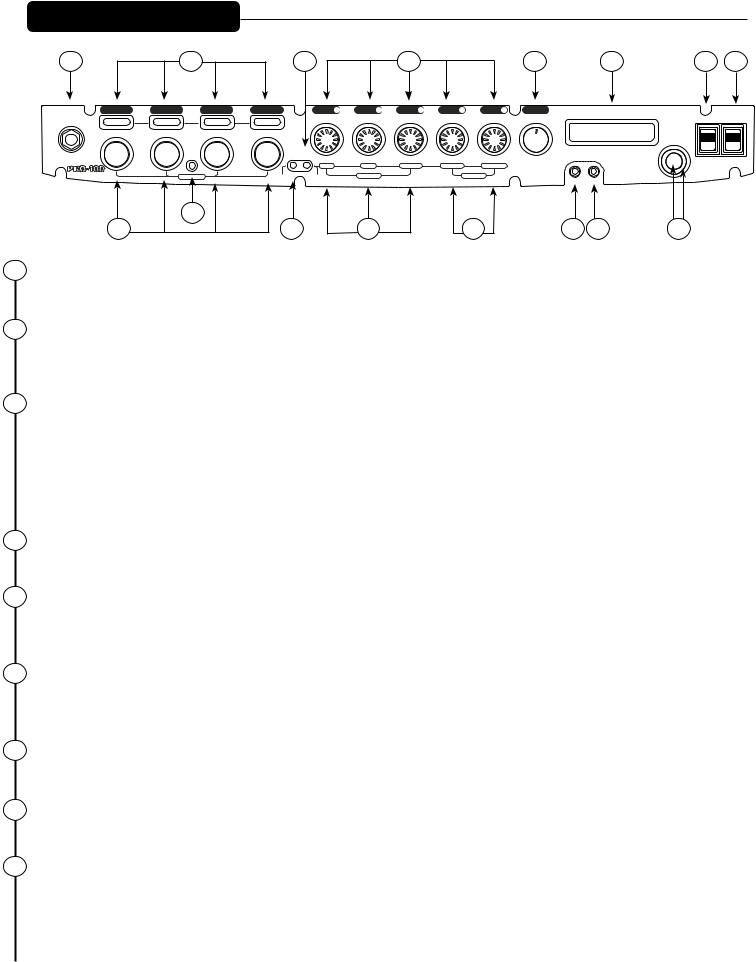
Front Panel continued
10Master Volume
Adjusts the overall loudness of the amplifier.
11Auxillary Input
This input allows for external audio sources, such as a CD or MP3 player.
12Headphone Jack
Output for Headphones, which can also be used as a direct output for recording, if needed.
13Master LCD Display Screen
Displays presets, modes, amp and effects parameters, as well as other information as needed.
14Bank Wheel (outer) and Preset Wheel (inner)
Allows user to scroll through Banks of presets (outer wheel) and through presets within a particular Bank (inner wheel). These knobs also are used in the Vypyr Main Menu to make selections and adjustments.
15Standby Switch
Allows amp to be placed in standby or active mode.
16Power Switch
Switch to “On” position to turn on.
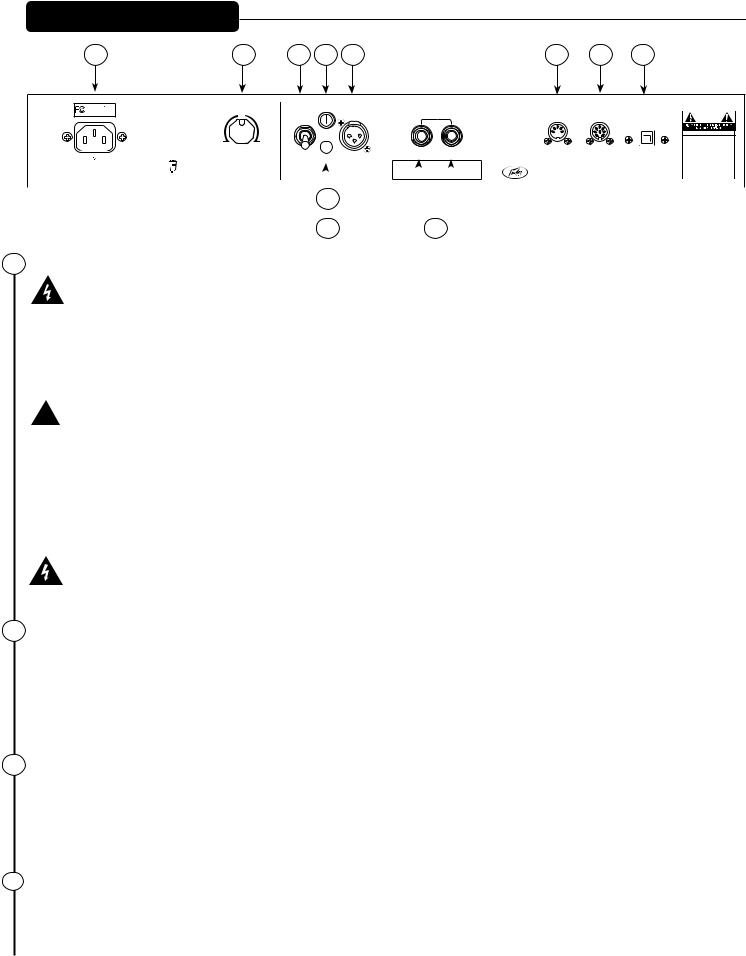
Rear Panel
17 |
18 |
20 |
21 |
23 |
25 |
26 |
27 |
Peavey
Electronics Corp.
VYPYR PRO-100
BUILT UNDER U.S. PATENT NOS.5,647,004; |
50% |
speaker |
level |
effects |
MIDI out |
footswitch |
USB |
EPO 0662752(GB DE); CANADIAN 2,139,717; |
out |
loop |
|
(or MIDI in) |
|
||
5,619,578; MEXICAN190,227; JP 2891326; |
|
|
|
|
|
|
|
CHINA ZL95101119.7; GERMANY 69510380.6; |
|
enable |
|
|
|
|
CAUTION |
TAIWAN R.O.C. INV. PAT NO. 075772 |
|
|
|
|
|
|
|
|
|
|
AVIS:RISQUE DE CHOC ELECTRIQUE |
|
|
|
NE PAS OUVRIR |
|
|
|
WARNING:TO REDUCE THE RISK OF FIRE |
|
|
|
OR ELECTRIC SHOCK, THIS APPARATUS |
CAN-ICES-3(B)/NMB-3(B) |
1% |
100% |
SHOULD NOT BE EXPOSED TO RAIN OR |
MOISTURE AND OBJECTS FILLED WITH |
|||
|
LIQUIDS, SUCH AS VASES, SHOULD NOT |
|
|
|
|
power sponge |
|
|
|
defeat |
|
|
|
|
|
send |
return |
|
|
REPLACE WITH SAME TYPE 250 VOLT FUSE. |
|||||||
|
|
|
|
|
® |
|
|
|
|
|
|
|
|
|
|
|
|
|
|
|
|
|
|
|
BE PLACED ON THIS APPARATUS. |
|
|
|
|
|
|
|
|
|
|
|
|
|
|
|
|
|
|
|
|
|
|
|
|
TO PREVENT THE RISK OF FIRE HAZARD, |
|
|
120V 60Hz |
|
|
|
|
ground lift |
|
|
|
|
|
|
|
|
|
|
|
|
|
AVIS: DANS LE BUT DE REDUIRE LES |
|||||
|
42 WATTS |
|
|
|
|
|
|
|
|
|
|
|
|
|
|
|
|
|
|
ELECTRIQUE, CET APPAREIL NE DOIT PAS |
|||||
Consumo de energia 42Wh |
|
|
|
|
|
|
|
|
|
TM |
|
|
|
|
|
|
Serial Sticker |
|
VYPYR® |
RISQUES D’INCENDIE OU DE DECHARGE |
|||||
|
|
|
|
|
|
|
|
|
|
|
|
|
|
|
A PRODUCT OF PEAVEY ELECTRONICS CORP. |
QU’UN VASE, NE DOIT ETRE POSE SUR |
|||||||||
|
|
|
|
|
|
|
|
|
|
MSDI |
|
|
|
|
|
|
|
|
|
|
|
DESIGNED AND ENGINEERED IN U.S.A. |
PRO-100 |
ET AUCUN OBJET REMPLI DE LIQUIDE, TEL |
|
Consumo de energia en modo de espera 42Wh |
|
|
|
|
|
|
|
|
|
|
|
|
|
|
|
|
|
|
CELUI-CI. REMPLACER PAR UN FUSIBLE DE |
||||||
|
|
|
|
|
(Mic |
Simulated Direct Interface) |
|
|
|
|
|
|
|
|
|
|
MADE IN CHINA |
MEME TYPE ET DE 250 VOLTS. |
|||||||
|
|
|
|
|
|
|
|
|
|
|
|
|
|
|
|
|
|
|
|
|
|
|
|
|
|
|
|
|
|
|
|
|
|
|
|
|
|
|
|
|
|
|
|
|
|
|
|
|
|
|
|
|
|
|
|
|
|
|
22 |
|
|
|
|
|
|
|
|
|
|
|
|
|
|
|
|||
|
|
|
|
|
|
|
|
|
19 |
|
|
|
|
|
|
|
|
|
24 |
|
|
|
|
|
|
|
|
|
|
|
|
|
|
|
|
|
|
|
|
|
|
|
|
|
|
|
|
|
|||
17 AC Power Inlet
This is the receptacle for an IEC line cord, which provides AC power to the unit. Connect the line cord to this connector to provide power to the unit. Damage to the equipment may result if improper
line voltage is used. Never break off the ground pin on any equipment. It is provided for your safety. If the outlet used does not have a ground pin, a suitable grounding adapter should be used and the third wire should be grounded properly. To prevent the risk of shock or fire hazard, always make sure that the amplifier and all associated equipment is properly grounded.
 NOTE: FOR UK ONLY
As the colours of the wires in the mains lead of this apparatus may not correspond with the coloured markings identifying the terminals in your plug, proceed as follows: (1) The wire which is coloured green and yellow must be connected to the terminal which is marked by the letter E, or by the Earth symbol, or coloured green or green and yellow. (2) The wire which is coloured blue must be connected to the terminal which is marked with the letter N, or the colour black. (3) The wire which is coloured brown must be connected to the terminal which is marked with the letter L, or the colour red.
To avoid the risk of electrical shock, do not place fingers or any other objects into empty tube sockets while power is being supplied to unit.
18Power Sponge
The Power Sponge allows the user to adjust the natural clipping or distortion of the power amp section of the amplifier. This feature allows the amplifier headroom to be raised or lowered, thus, allowing the amplifier to be “pushed” at a much lower volume. At a setting of 100%, the amp will have greater clean headroom; at 50%, the amp will begin to distort at the same volume. The maximum attenuation capability of this control can result in as low as 1% of the rated output power.
19MICROPHONE SIMULATED DIRECT INTERFACE - MSDI™
Peavey’s exclusive MSDI™ simulates the sound of a microphone placed approximately 8” from a loudspeaker cone, allowing the user to send an accurate, good quality signal to the mixing console without any acoustic spill from other instruments on stage. This is a non-powered output and safe for use with any mixing console. This output can also be used for recording.
20Speaker Engage/Defeat Switch
This effectively disconnects the speaker, and enables the user to monitor their playing using the signal from either the MSDI™ or USB outputs.
 Loading...