


Cover for T-MAX™
1

Intended to alert the user to the presence of uninsulated "dangerous voltage" within the product's enclosure that may be of sufficient magnitude to constitute a risk of electric shock to persons.
Intended to alert the user of the presence of important operating and maintenance (servicing) instructions in the literature accompanying the product.
CAUTION: Risk of electrical shock – DO NOT OPEN!
CAUTION: To reduce the risk of electric shock, do not remove cover. No user serviceable parts inside. Refer servicing to qualified service personnel.
WARNING: To prevent electrical shock or fire hazard, do not expose this appliance to rain or moisture. Before using this appliance, read the operating guide for further warnings.
Este símbolo tiene el propósito de alertar al usuario de la presencia de "(voltaje) peligroso" que no tiene aislamiento dentro de la caja del producto que puede tener una magnitud suficiente como para constituir riesgo de corrientazo.
Este símbolo tiene el propósito de alertar al usario de la presencia de instruccones importantes sobre la operación y mantenimiento en la literatura que viene con el producto.
PRECAUCION: Riesgo de corrientazo – No abra.
PRECAUCION: Para disminuír el riesgo de corrientazo, no abra la cubierta. No hay piezas adentro que el usario pueda reparar. Deje todo mantenimiento a los técnicos calificados.
ADVERTENCIA: Para evitar corrientazos o peligro de incendio, no deje expuesto a la lluvia o humedad este aparato Antes de usar este aparato, lea más advertencias en la guía de operación.
Ce symbole est utilisé pur indiquer à l'utilisateur la présence à l'intérieur de ce produit de tension non-isolée dangereuse pouvant être d'intensité suffisante pour constituer un risque de choc électrique.
Ce symbole est utilisé pour indiquer à l'utilisateur qu'il ou qu'elle trouvera d'importantes instructions sur l'utilisation et l'entretien (service) de l'appareil dans la littérature accompagnant le produit.
ATTENTION: Risques de choc électrique – NE PAS OUVRIR!
ATTENTION: Afin de réduire le risque de choc électrique, ne pas enlever le couvercle. Il ne se trouve à l'intérieur aucune pièce pouvant être réparée par l'utilisateur. Confier l'entretien à un personnel qualifié.
AVERTISSEMENT: Afin de prévenir les risques de décharge électrique ou de feu, n'exposez pas cet appareil à la pluie ou à l'humidité. Avant d'utiliser cet appareil, lisez les avertissements supplémentaires situés dans le guide.
Dieses Symbol soll den Anwender vor unisolierten gefährlichen Spannungen innerhalb des Gehäuses warnen, die von Ausreichender Stärke sind, um einen elektrischen Schlag verursachen zu können.
Dieses Symbol soll den Benutzer auf wichtige Instruktionen in der Bedienungsanleitung aufmerksam machen, die Handhabung und Wartung des Produkts betreffen.
VORSICHT: Risiko – Elektrischer Schlag! Nicht öffnen!
VORSICHT: Um das Risiko eines elektrischen Schlages zu vermeiden, nicht die Abdeckung enfernen. Es befinden sich keine Teile darin, die vom Anwender repariert werden könnten. Reparaturen nur von qualifiziertem Fachpersonal durchführen lassen.
ACHTUNG: Um einen elektrischen Schlag oder Feuergefahr zu vermeiden, sollte dieses Gerät nicht dem Regen oder Feuchtigkeit ausgesetzt werden. Vor Inbetriebnahme unbedingt die Bedienungsanleitung lesen.
2
Congratulations on the purchase of the Peavey T-MAX® bass amp! The two channel bass system is unlike any other amp available today. Not only does the T-MAX utilize tube technology for that smooth tube sound, but the T-MAX also has a completely independent solid-state channel! Two separate channels that are footswitchable and combinable make for an extremely versatile piece of gear. Besides the clean contemporary sound, the T-MAX is also capable of producing a smooth tube-distortion sound that can't be found in any modern solid-state bass rig!
FEATURES:
–1/4" input with -10 dB pad switch
–Active lowand high-shelving EQ with 7-band graphic EQ
–Front panel channel select and channel combine switches
–Channel active LEDs
–Variable (100 Hz - 1 kHz) third-octave crossover with frequency and balance controls
–Front panel graphic in/out switch
–Footswitchable: channel select, graphic in/out, and effects loop
–Low Z balanced line out with pre/post EQ switch
–Ground lift switch for line out
–Two paralleled speaker jacks
–Preamp out/power amp in jacks
–Crossover low and high out jacks
–Effects send and return jacks
–Effects high and low level switch
–Two-rack-space package
3

E N G L I S H
1 |
4 |
7 |
9 |
11 |
13 |
15 |
17 |
2 |
3 |
5 |
6 |
8 |
10 |
12 |
14 |
16 |
19 |
18 |
INPUT PAD SWITCH (1)
Provided for instruments that have extremely high output, which can result in overdriving (distorting) the input gain stage. Depressing the switch to its "in" position reduces the level of the input signal by 10 dB.
INPUT (2)
This input will accept signals from all types of bass pickups.
PRE GAIN (3)
Controls the input gain of the tube channel.
CHANNEL STATUS LED (4)
Illuminates when channel is activated.
POST GAIN (5)
Controls the overall volume level of the channel. The master volume adjustment should be made after the desired sound has been achieved.
PRE GAIN (6)
Controls the input gain of the solid-state channel.
CHANNEL STATUS LED (7)
Illuminates when channel is activated.
INPUT CLIP INDICATOR (8)
This LED indicates (when lit) that the input gain stage is being overdriven (distorted). Depressing the input pad switch to its "in" position or reducing the pre gain will alleviate this problem.
CHANNEL SELECT SWITCH (9)
Allows selection of the tube or solid-state channel. The "in" position of the switch selects the solid-state channel, and the "out" position selects the tube channel.
NOTE: Channel selection may also be accomplished by the remote footswitch. If the remote selection is desired, the select switch must be in the "out" (tube) position.
CHANNEL COMBINE SWITCH (10)
Allows selection of single channel or combined channel operation. The "in" position of the switch selects combined channel operation where both channels operate simultaneously. The "out" position selects single channel operation.
HIGH (11)
An active tone control (shelving type, ±15 dB) that varies the high frequency boost or cut.
4
LOW (12)
An active tone control (shelving type, ±15 dB) that varies the low frequency boost or cut.
GRAPHIC SELECT (13)
The "in" position of this switch routes the signal through the graphic equalizer. The "out" position removes the graphic equalizer from the signal path.
7-BAND GRAPHIC EQ (14)
A 7-band, two-and-one-half-octave graphic equalizer that provides 15 dB of boost or cut at each center frequency.
CROSSOVER BALANCE CONTROL (15)
Controls the relative levels of output signals from the crossover. Adjusting this control will only affect signals at the High Range Output Jack and the Low Range Output Jack on the rear panel. All other output signals are unaffected by this control.
MASTER VOLUME (16)
Controls the overall volume level of the system.
CROSSOVER FREQUENCY (17)
The frequency control varies the crossover frequency from 100 Hz to 1 kHz.
POWER LED/DDT™ INDICATOR (18)
The LED is green when the power switch is in the "on" position. During normal operation, this LED also acts as a DDT™ indicator. The LED illuminates "red" when DDT™ power amp compression is taking place.
POWER SWITCH (19)
Used to turn AC mains power on or off.
20 |
21 |
22 |
23 |
24 |
25 |
26 |
27 |
28 |
29 |
30 |
31 |
32 |
33 |
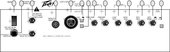
CIRCUIT BREAKER (20)
This breaker is provided to limit the current to the power transformer, and thereby protect it from overheating and possible destruction due to faulty conditions in the amplifier. The trip current value has been carefully chosen to allow continuous power output performance, while still providing adequate protection for the power transformer. Normally this breaker should not trip unless there is a fault in the amplifier circuitry that draws excessive mains current. However, abnormal conditions, such as a short circuit or continuous operation at overload or clipping, will cause the breaker to trip. If this occurs, simply reset the breaker and correct the cause of the overload. When tripped, the button on the breaker will be outward nearly 1/2" and can be reset by pushing inward. A normal reset button length is about 1/4". If this “thermal” type breaker does trip, then simply pushing the button back in will reset it after waiting a brief period of time to allow it to cool down. If the breaker trips instantly each time you attempt to reset it, then the unit should be taken to a qualified service center for repair.
5
LINE CORD (120 V PRODUCTS ONLY) (21)
For your safety, we have incorporated a 3-wire line (mains) cable with proper grounding facilities. It is not advisable to remove the ground pin under any circumstances. If it is necessary to use the equipment without proper grounding facilities, suitable grounding adaptors should be used. Less noise and greatly reduced shock hazard exist when the unit is operated with the proper grounded receptacles.
SPEAKER JACKS (22)
Provided for connection of external speakers or speaker enclosure. Minimum total impedance is 2 ohms.
REMOTE SWITCH DIN JACK (23)
Provided for optional footswitch. Allows remote selection of channel select, graphic in/out, and effects loop (post EQ).
LINE OUT (LOW Z BALANCED) (24)
An XLR jack is provided to route the signal to mixing/recording consoles. This output can be selected pre or post EQ.
LINE OUT SELECT SWITCH (25)
Allows selection of pre EQ or post EQ to the Low Z balanced line out jack. The “in” position selects pre EQ line out, and the “out” position selects post EQ line out.
LINE OUT GROUND LIFT SWITCH (26)
Provides ground to be made from the line out jack or lifted to eliminate ground loop from unit and external source. There may be some situations when audible hum and/or noise will come from the loudspeaker. Select the ground switch to either the in or out position to minimize the noise.
POWER AMP INPUT (27)
Used to connect line level signal to the power amplifier.
PREAMP OUT (28)
The preamp output can be used to route the amplified signal to a mixing console, tape recorder, etc. Connect the preamp output using a shielded cable to an input of the tape recorder, mixer, etc. This patch does not affect the operation of the amplifier.
CROSSOVER (LOW OUT) (29)
Provides a post crossover low-range output signal. Signal level is adjusted by the master volume control and the crossover balance control.
CROSSOVER (HIGH OUT) (30)
Provides a post crossover high range output signal. Signal level is adjusted by the master volume control and the crossover balance control.
EFFECTS RETURN (31)
Input for returning signals from external low-level effects or signal processing equipment.
EFFECTS SEND (32)
Output for supplying signals to external low-level effects or signal processing equipment.
EFX LEVEL SWITCH (33)
Selects the effects loop operating level: -10 dBV (3 V RMS) when in low position and 0 dBV (1 V RMS) when in high position.
6
 Loading...