


PV®10AT • PV®10BT
Compact Mixer
|
|
|
|
|
|
|
|
|
|
|
1/4”-Hi-Z CH.4 Only |
|
|
|
USB A |
|
|
|
|
|
MAIN |
|
|
|
|
||||
|
|
|
|
|
|
|
|
|
|
|
|
|
|
|
|
|
|
|
|
|
|
|
|
|
L |
||||
|
|
|
|
|
|
|
|
|
|
|
|
|
|
|
|
|
|
|
|
|
|
OUTPUTS |
|
||||||
|
|
|
|
|
|
|
|
|
|
|
|
|
|
|
|
|
|
|
|
|
|
|
|
|
|
|
|||
|
|
|
|
|
|
|
|
|
|
|
|
|
|
3.5mm STEREO |
|
|
|
|
|
FS |
|
|
|
|
|
|
|
||
DIRECT OUT |
DIRECT OUT |
DIRECT OUT |
DIRECT OUT |
L |
|
5 |
|
|
|
AUX SEND L |
9 |
|
|
|
L |
|
R |
||||||||||||
|
|
|
|
|
|
|
|
STEREO IN |
|
|
|
|
|
Operating |
|||||||||||||||
|
|
|
|
|
|
|
|
|
|
|
|
|
|
|
|
|
|
|
|
|
|
|
|
|
|
|
|||
|
|
|
|
|
|
|
|
|
|
|
|
|
|
|
|
|
PAIRING |
|
|
|
|
|
|
|
|
|
|||
|
|
|
|
|
|
|
|
|
|
|
|
|
|
|
|
|
|
|
|
|
|
|
|
|
|
|
|||
|
|
|
1 |
|
|
|
2 |
|
|
3 |
|
|
4 |
R |
|
6 |
|
|
|
|
|
R |
10 |
|
|
|
R |
|
|
|
|
|
|
|
|
|
|
|
|
|
|
5/6 |
|
|
7/8 |
|
|
|
9/10 |
|
|
|
|
|
Manual |
||||
PV 10AT |
|
|
|
|
|
|
|
|
|
|
|
|
|
|
|
|
|||||||||||||
|
|
|
|
|
|
|
|
|
|
|
|
10 INPUT STEREO MIXER |
|
|
|
|
|
|
|
|
|
|
|||||||
|
|
|
|
|
|
|
|
|
|
|
|
WITH DIGITAL EFFECTS, MEDIA PLAYBACK AND BLUETOOTH |
|
|
|
|
|
|
|||||||||||
|
|
|
AT |
|
|
|
AT |
Auto-TUNE |
|
|
|
ELECTRIC GUITAR PRE-SHAPE |
|
|
|
|
|
|
|
|
|
||||||||
HI PASS |
|
HI PASS |
|
HI PASS |
|
HI PASS |
|
L |
|
R |
|
|
|
PHANTOM POWER |
9/10 |
|
|
|
|
|
|
||||||||
|
|
|
|
|
|
|
|
|
|
|
|
|
|
|
|
|
|
|
|
|
|
|
|
|
|
|
|
||
|
|
|
|
|
|
|
|
|
|
|
|
|
|
|
|
|
USB B |
|
48V |
|
|
|
|
|
|
|
PV 10 |
||
|
|
|
|
|
|
|
|
|
|
|
|
|
|
|
|
|
|
|
|
|
|
|
|
|
|
||||
|
|
|
|
|
|
|
|
|
|
|
|
|
|
|
|
|
USB A |
|
|
|
|
|
|
|
|
|
|
||
min |
|
max |
min |
|
max |
min |
|
max |
min |
|
max |
|
|
|
Bluetooth |
|
|
min |
max |
CONTROL ROOM |
|
L |
R |
||||||
GAIN |
GAIN |
GAIN |
GAIN |
|
|
|
|
|
|
|
|
|
|||||||||||||||||
comp |
|
|
comp |
|
|
|
|
|
|
|
|
|
|
|
|
|
|
STEREO IN LEVEL |
|
SOLO/MAIN |
A |
|
|
||||||
|
|
|
|
|
|
|
|
|
|
|
|
|
|
|
|
|
|
|
|
|
|
|
|
|
A/B SELECT |
|
|
|
|
|
|
|
|
|
|
|
|
|
|
|
|
|
|
|
|
|
|
|
|
|
|
|
|
|
|
|
|
|
|
|
|
|
|
|
|
|
|
|
|
|
|
|
|
|
|
|
|
|
|
|
|
|
|
|
B/REC |
|
B/ |
|
|
min |
COMP |
max |
min |
COMP |
max |
|
|
|
|
|
|
min |
GAIN |
max |
min |
GAIN |
max |
min |
max |
min |
max |
|
|
REC |
|
|
|||
|
|
|
|
|
|
|
|
|
|
|
|
|
|
LEVEL A/B |
REC LEVEL |
|
|
|
|
|
|
||||||||
min |
|
HIGH |
max |
min |
|
HIGH |
max |
min |
HIGH |
max |
min |
HIGH |
max |
min |
HIGH |
max |
min |
HIGH |
max |
min |
max |
min |
max |
|
|
|
|
|
USB |
|
|
|
|
|
|
|
|
|
|
|
|
|
|
RECORD LEVEL |
TO CONTROL ROOM |
|
|
|
|
|
|||||||||
|
|
|
|
|
|
|
|
|
|
|
|
|
|
|
|
|
|
|
|
Press to |
|
|
EFFECTS |
|
|
|
|
Press to |
|
|
|
|
|
|
|
|
|
|
|
|
|
|
|
|
|
|
|
|
|
|
|
MEDIA |
|
|
|
|
Select |
||
|
|
|
|
|
|
|
|
|
|
|
|
|
|
|
|
|
|
|
|
Select |
|
|
|
|
|
|
or edit |
||
low |
|
|
high |
low |
|
|
high |
low |
|
high |
low |
|
high |
min |
MID |
max |
min |
MID |
max |
|
|
|
|
|
|
|
|
|
|
MID-MORPH |
MID-MORPH |
MID-MORPH |
MID-MORPH |
|
|
|
|
MEDIA SELECT |
|
|
|
|
EFX SELECT |
||||||||||||||||
|
|
|
|
|
|
|
|
|
|
|
|
|
|
|
|
|
|
|
|
|
|
|
|
||||||
|
|
|
|
|
|
|
|
|
|
|
|
|
|
|
|
|
|
|
|
|
|
|
|
|
|
|
|
|
Auto- |
min |
|
|
max |
min |
|
|
max |
min |
|
max |
min |
|
max |
min |
|
max |
min |
|
max |
|
|
|
|
|
|
|
|
|
TUNE |
|
LOW |
|
LOW |
LOW |
LOW |
LOW |
LOW |
|
|
|
USB MEDIA PLAYBACK |
|
|
|
|
||||||||||||||
|
|
|
|
|
|
|
|
|
|
|
|
|
|
|
|
|
|
|
|
|
|||||||||
|
|
|
|
|
|
|
|
|
|
|
|
|
|
|
|
|
|
DIGITAL EFFECT/MEDIA PLAYBACK |
|||||||||||
EQ BYPASS |
|
EQ BYPASS |
|
EQ BYPASS |
|
EQ BYPASS |
|
|
|
|
|
|
|
|
|
|
|
||||||||||||
|
|
|
|
|
|
|
|
|
|
|
|
|
|
|
|
|
|
|
|
|
|
SOLO |
|
|
|
|
|
|
|
min |
AUX |
max |
min |
AUX |
max |
min |
AUX |
max |
min |
AUX |
max |
min |
AUX |
max |
min |
AUX |
max |
min |
max |
|
|
|
AUX |
min |
max |
||||
|
|
|
|
|
|
|
|
|
|
|
|
|
|
MASTER |
|
|
|
|
|
HIGH |
|||||||||
|
|
|
|
|
|
|
|
|
|
|
|
|
|
|
|
|
|
|
|
|
|
SOLO |
|
|
EFX |
|
|
|
|
|
|
|
|
|
|
|
|
|
|
|
|
|
|
|
|
|
|
|
|
|
|
|
|
MUTE |
|
|
|
|
|
min |
|
max |
min |
|
max |
min |
|
max |
min |
|
max |
ANALOG |
|
DIGITAL |
|
min |
max |
|
|
min |
max |
EFX |
min |
max |
|||||
EFX |
EFX |
EFX |
EFX |
MEDIA CHANNEL |
MEDIA CHANNEL |
|
|
||||||||||||||||||||||
|
|
|
|
|
|
|
|
|
|
RETURN TO MAIN |
|
|
RETURN TO AUX |
|
LOW |
||||||||||||||
|
|
|
|
|
|
|
|
|
|
|
|
|
|
|
|
|
|
|
|
|
|
|
|
L |
R |
|
|
|
|
|
|
|
|
|
|
|
|
|
|
|
|
|
|
|
|
|
|
|
|
STEREO |
|
MONO |
|
|
|
|
|
ENABLE |
|
|
|
|
|
|
|
|
|
|
|
|
|
|
|
|
|
|
|
|
|
|
|
(SUM) |
|
|
|
|
|
|
|
left |
|
PAN |
right |
left |
|
PAN |
right |
left |
PAN |
right |
left |
PAN |
right |
left |
BAL |
right |
left |
BAL |
right |
|
|
|
|
|
|
|
|
KOSMOS-C |
|
|
|
|
|
|
|
|
|
|
|
|
|
|
|
|
|
|
|
|
|
|
|
||||||||
CLIP |
|
MUTE |
CLIP |
|
MUTE |
CLIP |
MUTE |
CLIP |
MUTE |
CLIP |
MUTE |
CLIP |
MUTE |
MIC MUTE |
|
|
|
|
|
HEADPHONE/ |
|||||||||
|
|
|
|
|
|
|
|
|
|
|
|
|
|
|
|
|
|
|
|
|
|
|
|
|
|
|
|
SOLO/MAIN |
|
SIGNAL |
1 SIGNAL |
2 SIGNAL |
|
3 SIGNAL |
|
4 SIGNAL |
5/6 SIGNAL |
7/8 |
|
|
|
|
|
|
|
|
|
|
|||||||||||
min LEVEL max |
min LEVEL max |
min LEVEL max |
min LEVEL max |
min LEVEL max |
min LEVEL max |
L |
|
R |
|
|
|
|
|
min |
max |
||||||||||||||
SOLO |
|
|
|
|
|
LEVEL |
|||||||||||||||||||||||
SOLO |
|
1 |
SOLO |
|
2 |
SOLO |
|
3 |
SOLO |
|
4 |
SOLO |
5/6 |
SOLO |
7/8 |
|
|
|
|
|
|
|
|
|
|
||||
|
|
|
|
|
|
|
|
|
|
|
|
MAIN L+R |
|
|
|
|
|
SOLO/MAIN |
|||||||||||
www.peavey.com

FCC/ICES Compliancy Statement
This device complies with Part 15 of the FCC rules and Industry Canada license-exempt RSS Standard(s). Operation is subject to the following two conditions: (1) this device may not cause harmful interference, and (2) this device must accept any interference received, that may cause undesired operation.
Le présent appareil est conforme aux CNR d’lndustrie Canada applicables aux appareils radio exempts de licence. L’exploitation est autorisée aux deux conditions suivantes: (1) I’appareil ne doit pas produire de brouillage, et (2) I’utilisateur de I’appareil doit accepter tout brouillage radioélectrique subi, même si le brouillage est susceptible d’en compromettre le fonctionnement.
Warning: Changes or modifications to the equipment not approved by Peavey Electronics Corp. can void the user’s authority to use the equipment.
Note – This equipment has been tested and found to comply with the limits for a Class B digital device, pursuant to Part 15 of the FCC Rules. These limits are designed to provide reasonable protection against harmful interference in a residential installation. This equipment generates, uses, and can radiate radio frequency energy and, if not installed and used in accordance with the instructions, may cause harmful interference to radio communications. However, there is no guarantee that interference will not occur in a particular installation. If this equipment does cause harmful interference to radio or television reception, which can be determined by turning the equipment off and on, the user is encouraged to try and correct the interference by one or more of the following measures.
•Reorient or relocate the receiving antenna.
•Increase the separation between the equipment and receiver.
•Connect the equipment into an outlet on a circuit different from that to which the receiver is connected.
•Consult the dealer or an experienced radio/TV technician for help.
Caution
The equipment complies with FCC radiation exposure limits set forth for an uncontrolled environment.
Features and specifications are subject to change without notice.
Peavey Electronics Corporation • 711 A Street • Meridian, MS 39301 (601) 483-5365 • FAX (601) 486-1278 • www.peavey.com
© 2015 |
EX000030 |

ENGLISH
PV®10AT and PV®10BT
Compact Mixers
Congratulations on purchasing the Peavey PV®10AT or PV®10BT Compact Mixer. The PV®10AT and PV®10BT are studio-quality mixing consoles designed to meet diverse needs while occupying a small space. These are the perfect consoles for small venue performances or home recording environments. PV series mixers feature built-in DSP effects that are useful in real-world recording and sound reinforcement, while parameter controls allow you to tailor each effect to meet your needs.
The PV 10 BT includes 4 channels of reference-quality mic preamps, 4 direct outputs for recording, a stereo channel, media channel with Bluetooth wireless input, high quality digital effects with LCD display, streaming USB out, MP3 playback via USB A input, Peavey's exclusive Kosmos audio enhancement, 48 volt phantom power, dual selectable control room outputs, 2 channels of compression, one channel of on board selectable guitar preamp, 3-band EQ per channel with bypass, channel mute buttons, aux send, signal clip indicators, and a stereo master LED meter bridge. This amazingly versatile mixer is at home both in the studio as well as live applications. Its modern features such as Bluetooth allow seamless connection to almost any "smart" device. 4 direct outs allow easy connection to most DAW interfaces for recording; in addition, the PV 10 BT can stream audio directly to a PC. MP3 playback is also available, just plug a flash drive with MP3 files on it into the USB A port and use the LCD to select and playback music. The PV series Solo feature allows the user to listen to individual channels via headphone or control room outputs and the EQ bypass allows the user to compare the EQ'd signal to the original signal with the push of a button. 2 Channels of compression keep signals with difficult levels under control, and Peavey's exclusive guitar-shape adjusts the EQ and preamp specifically for guitar. Hi pass filters on every channel remove unwanted rumble and noise, and balanced AUX and Master outputs ensure a clean noise free signal to your powered speakers or power amplifier. The all new PV series non-powered mixers represent the pinnacle of performance and value. Combine Peavey's legendary reliability and our 5 year warranty and you can be assure of years of quality reliable service, we guarantee it.
In addition to all of these features, the PV10AT features 2 channels of Antares® world-famous Autotune®, which can be set to subtly tighten up vocal harmonies, or it can be set for robotic vocal effects heard in today's popular music. Peavey's exclusive custom key feature makes it a snap to auto-tune to any scale you can think of, in a live performance. It is so easy and fast, you can set it up between songs, right in the middle of a set.
Please read this guide carefully to ensure your personal safety as well as the safety of your equipment.
FEATURES: |
|
• 4 Combination 1/4" and XLR low noise mic preamps |
• 2 channels of built-in compression |
• Stereo 1/4", RCA or 3.5mm input channel |
• Stereo pan control per channel |
• Bluetooth wireless connectivity |
• On-board USB-A MP3 playback |
• 3-band EQ on all channels |
• 4 Channels of direct out |
• 4 Channels of Peavey's Exclusive Mid-Morph |
• Kosmos -C bass and treble enhancement |
• 150 Hz low-cut switch on all mic inputs |
• Channel 9/10 stereo return/input |
• LED clip and signal present indication |
• Individual Solo function |
• Individual channel mutes |
• Stereo USB-B streaming audio in and out |
• EQ Bypass per mic channel |
• High quality master LED meter bridge |
• On board studio quality digital effects with individual channel control |
• Master mic mute |
• Effects and playback LCD display |
• Studio quality headphone output |
• One pre-fader AUX send |
• Peavey's exclusive on-board 1 Meg guitar input |
• Precision 60 mm faders on master |
• Antares Auto-Tune with Peavey's exclusive Custom Key |
• Dual selectable control room outputs / Record out with independent level |
feature |
|
|
• Global 48V phantom power |
|
• Main stereo outputs with balanced 1/4" and XLR connectors |
|
• Rugged console design |
|
Installation Note: |
|
This unit must have the following clearances from any combustible surface: top: 8", sides: 12", back: 12"

PV10AT Front Panel (channels 1 and 2)
1MIC/LINE INPUT (CH.1-8)
This combination input jack accepts a ¼” or XLR balanced plug. The XLR balanced input is optimized for a microphone or other low impedance source. The ¼” input is a TRS balanced type, and also accepts ordinary TS guitar cables.
2DIRECT OUT
This impedance-balanced TRS output signal is taken after the mic preamp, hi pass filter, and compressor, but before the EQ stage.
3AUTO-TUNE ACTIVATION BUTTON AND LED (PV10AT only)
Pressing this button activates the PV10AT's onboard AUTO-TUNE feature. The button illuminates when in AUTO-TUNE mode (SEE Effects Select {50} and the following page).
4GAIN
The Input Gain control is used to establish proper gain structure in the channel. For best results, use the Solo system (19) to monitor the channel while you set the gain. The goal is maximum gain without distor-
tion. Both the main LED meters (during Solo) and the channel’s Signal/Clip indicator (16,17) can be used 7 for adjusting gain. If the clip LED (16) comes on and remains lit, try reducing the gain.
5150 Hz HI PASS FILTER
The hi pass filter has a corner frequency of 150 Hz. When engaged‚ it can improve clarity by removing low frequencies that make a mix sound muddy. This feature is especially useful when playing outside on a windy day or on a hollow-sounding‚ noisy stage. These kinds of ambient noises can rob your sound system of power. Engaging this switch will remove those frequencies from the system and restore power where needed.
6COMPRESSION CONTROL (Channels 1 and 2 only)
Adjusting this knob clockwise lowers the threshold of the compressor, thereby increasing the amount of compression. The compressor ratio is in the 4:1 range, varying with signal levels and the amount of compression. This is useful for controlling peak levels from live sources, and has been designed to subtly tame the levels of live vocals without noticeable artifacts. The compressor is after the gain control (5) and the hi pass filter (4), but before the direct out (2), so it can be patched to external equipment.
7Compressor LED
This LED illuminates when the compressor is actively compressing a signal.
8Hi EQ
This active tone control (shelving type: ±15 dB) varies the level of the high frequency range.
9MID-MORPH EQ (CH. 1-7)
Where most mid-range controls work at just one frequency, the Mid-Morph works at two. When turned |
|
|
counterclockwise, it cuts at 250Hz to reduce frequencies that muddy the sound. When turned clockwise, |
|
|
it boosts at 4kHz to add intelligibility to vocals. Either way, improved vocal or instrument definition can |
|
|
be achieved. |
|
|
10 Low EQ |
|
|
This active tone control (shelving type: ±15 dB) varies the level of the low frequency range. Caution: Ex- 16 |
||
cessive low frequency boost causes greater power consumption and increases the possibility of speaker |
17 |
|
damage. |
||
|
||
11EQ BYPASS
Engaging this button bypasses the equalization of the channel, allowing you to easily hear the effect of the EQ settings.
12AUX SEND
This control adjusts the level of the channel signal sent to the Aux output. The signal is taken before the channel level (18) but after the channel EQ, meaning that changes to the EQ settings will affect the aux mix, but changes to the channel level control won't. Typical use for the Aux bus is to feed stage monitors, when used in a live performance, or to feed headphone amplifiers in a recording situation.
1
DIRECT OUT
2
1
|
|
AT |
3 |
|
|
|
|
HI PASS |
|
4 |
|
|
|
||
|
|
|
5 |
min |
GAIN |
max |
|
comp |
|
|
|
|
|
|
6 |
minCOMP max |
|
||
|
|
|
8 |
min HIGH max |
|
||
|
|
|
9 |
low |
|
high |
|
MID-MORPH |
|
||
|
|
|
10 |
min |
LOW |
max |
11 |
EQ BYPASS |
|
||
|
|
|
12 |
min AUX max |
|
||
|
|
|
13 |
min |
EFX |
max |
|
|
|
|
14 |
left |
PAN |
right |
|
|
|
|
|
CLIP |
MUTE |
|
|
|
|
15 |
|
|
|
|
|
SIGNAL |
1 |
|
|
|
|
|
|
|
|
|
18 |
min LEVEL max |
|
||
SOLO |
|
1 |
19 |
|
|
|
|
PV10AT Front Panel (channels 1 and 2)
13EFX SEND
This control adjusts the level of the channel signal added to the effects mix. The signal is sent to the internal effects processor. Turning the knob to the left (min) will turn off effects on the associated channel, while turning the knob to the right will increase the amount of the selected effect. The effects send signal is taken after the channel level (18) so that adjustments made to the fader will also affect the send level.
14PAN CONTROL
This knob controls the placement of the signal in the stereo field. When rotated completely counterclockwise‚ the signal is present only on the left channel; when rotated completely clockwise‚ only in the right channel. This control functions as a balance control to adjust the relative level of the left and right signals on stereo channels 5/6 and 7/8. (Note 1/4" inputs on ch 5-6 and 9-10 are mono unless both are connected, then they switch to stereo)
15MUTE SWITCH
Pressing this switch will silence the channel signal going to the main mix, aux send, and effects. The mute switch will not affect the signal sent to the solo system.
16CLIP/MUTE LED
This LED normally indicates that the channel signal level is near clipping (distortion), but it also lights when mute is engaged. The clip indicator circuit monitors the signal after the gain control, after the EQ, and after the main level; because clipping can be caused by high settings of any of these controls. It illuminates at +15 dBu with a static signal (test tone), and corresponds to audible clipping with a highly dynamic signal (i.e.
piano). When lit, it warns that the gain or EQ boost should be reduced. When it lights, roughly 5 dB of headroom remains. An optimized setting of input gain + EQ will result in this LED flashing briefly on the loudest peaks.
17SIGNAL LED
The signal LED lights when the channel level reaches approximately -20 dBu. This not only indicates which channels are active, but also serves as a mini level meter. Because its illumination varies with the signal source, it is useful in identifying which channel is carrying a particular source.
18CHANNEL LEVEL CONTROL
This is the channel's output control, which sets the signal level sent to the left and right mix and the effects send control. The gain is 0 dB (unity gain) when set to the detent at mid-rotation (12:00). 10 dB of boost is available at the max gain setting. Normal operation is to start with this knob at the detent, and set the input gain and EQ with the source playing such that normal levels are seen at the signal /clip LED's and the main meter array. As additional sources are added, it is normal to turn this knob down slightly to prevent overdriving the main mix bus.
19SOLO SWITCH AND LED
When the Solo switch is engaged, the yellow LED lights, as does the yellow Solo LED under the main L/R meter array in the master section, indicating that the Solo system is now active. The Solo system is a separate mix bus that routes the soloed channel(s) at unity gain to the level meters for precise input level setting, and to the control room monitor and headphone outputs for critical listening to the selected
source(s). When the Solo system is active, the complete mix will no longer be heard through the control room or headphones; only the soloed channel(s).
PV10AT Front Panel (channel 4)
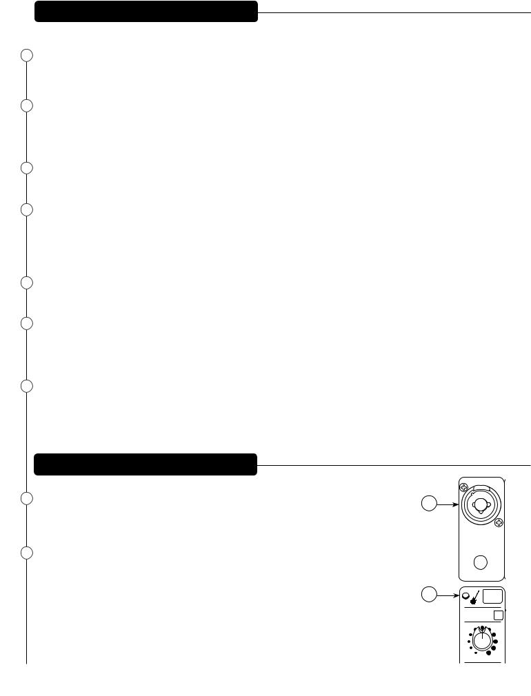
20MIC/LINE INPUT (CHANNEL 4 ONLY)
This input is the same as channels 1-3 unless Guitar Shape is pressed. When ELECTRIC GUITAR PRE-SHAPE is on, the 1/4" input changes to a high impedance (1 MegΩ), like a 12AX7 vacuum tube guitar amplifier input.
21Electric Guitar Pre-Shape
Engaging this button optimizes the on board equalization for electric guitar.
1/4”-Hi-Z CH.4 Only
20
DIRECT OUT
 4
4
21
HI PASS
min GAIN max
PV10AT/PV10BT Front Panel (channels 5, 6, 7 and 8)
22 |
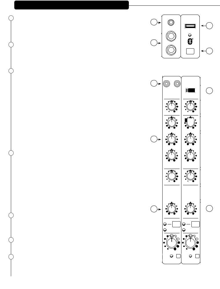
3.5mm STEREO INPUT |
22 |
|
The 3.5mm input to channel 5/6 accepts a stereo input from the output of an MP3 player, |
|
|
CD player, tape deck or other similar device. This input is optimized for portable hand- |
|
|
held devices and therefore has very high sensitivity. |
|
23 |
STEREO INPUTS |
23 |
|
||
|
Channels 5 and 6 also feature 1/4" inputs. If only one jack is used, it behaves as a mono |
|
|
source with a pan control. When both jacks are connected, these connections serve as a |
|
|
stereo source with a balance control; 5 is Left and 6 is Right. |
|
24 |
USB MEDIA JACK |
|
|
A-type USB connector that a removable data storage device can be connected to playback |
|
|
music |
26 |
|
USB PLAYBACK: |
|
|
First, slide the input selection switch (27) to the USB A position. The bottom of the LCD |
|
|
display will say “Insert USB drive”. Insert your USB drive into the USB Media Jack (24) |
|
|
at the top of channel 7/8. The Media Player will now enter "Folder Navigation Mode". In |
|
|
this mode, you can scroll through a list of all folders on the USB drive. Once you select |
|
|
a folder, the Media Player will enter "Song Navigation Mode" which allows you to scroll |
|
|
through a list of all songs contained in the selected folder. If there are no songs in the |
|
|
selected folder, the LCD will display "No Songs". To return to Folder Navigation Mode, scroll |
|
|
to the very beginning of the list and select the <FOLDERS> option. |
|
|
Once a song is finished playing, the Media Player will automatically start playing the next |
|
|
song. Once the Media Player reaches the last song, it will automatically loop back to the |
28 |
|
beginning of the list. |
|
|
|
|
25 |
BLUETOOTH PAIRING BUTTON AND LED |
|
|
The Bluetooth Pairing Button is used to turn on/off the Bluetooth. Once turned on, the |
|
|
Bluetooth will automatically enter pairing mode. You can pair any Bluetooth-enabled |
|
|
device with the mixer using the PIN 7878. The blue “Bluetooth Active LED” indicates the |
|
|
status of the Bluetooth connection. If the LED is off, the Bluetooth module is powered |
|
|
off. If the LED is slowly flashing, the PV mixer is not paired with any device, but is avail- |
|
|
able for connection. When the LED is lit solid, the source device is properly paired to the |
|
|
mixer and ready to play. To clear the paired device memory, make sure Bluetooth is on |
|
|
and press and hold the Bluetooth Pairing Button for 5 seconds. The PV mixer will ask if |
|
|
you would like to clear the Bluetooth memory. Select "Y" using the Media Select knob |
|
|
to clear the memory. The PV mixer will go through the process of clearing the memory, |
|
|
which should take approximately 15 seconds. |
29 |
|
|
26RCA MEDIA INPUTS
The RCA inputs to channel 5/6 accept a stereo source such as an MP3 player, CD player, tape deck or other similar device. This input is optimized for portable handheld devices and therefore has very high sensitivity.
27DIGITAL SOURCE SELECTOR
This switch selects between USB A (24), USB B (68), and the internal Bluetooth receiver.
28 MID CONTROL
Stereo channels' midrange is +/-20 dB @ 440Hz ; the HIGH (8) and LOW (10) controls are described above.
|
|
USB A |
3.5mm STEREO |
|
24 |
|
|
|
L |
5 |
|
|
|
PAIRING |
R |
6 |
25 |
5/6 7/8
L R
USB B
 27
27
USB A Bluetooth
min GAIN max
min HIGH max
min MID max
min LOW max
min AUX max
min GAIN max
min HIGH max
min MID max
min LOW max
min AUX max
ANALOG |
DIGITAL |
MEDIA CHANNEL |
MEDIA CHANNEL |
 30
30
left |
right |
left |
right |
|
BAL |
|
BAL |
CLIP |
MUTE |
CLIP |
MUTE |
|
|
||
SIGNAL |
5/6 |
SIGNAL |
7/8 |
min LEVEL max min LEVEL max
SOLO SOLO
5/6 7/8
7/8
 Loading...