


MP™ 600
P o w e r e d M i x e r
Operating Guide
Intended to alert the user to the presence of uninsulated “dangerous voltage” within the product’s enclosure that may be of sufficient magnitude to constitute a risk of electric shock to persons.
Intended to alert the user of the presence of important operating and maintenance (servicing) instructions in the literature accompanying the product.
CAUTION: Risk of electrical shock — DO NOT OPEN!
CAUTION: To reduce the risk of electric shock, do not remove cover. No user serviceable parts inside. Refer servicing to qualified service personnel.
WARNING: To prevent electrical shock or fire hazard, do not expose this appliance to rain or moisture. Before using this appliance, read the operating guide for further warnings.
Este símbolo tiene el propósito, de alertar al usuario de la presencia de “(voltaje) peligroso” sin aislamiento dentro de la caja del producto y que puede tener una magnitud suficiente como para constituir riesgo de descarga eléctrica.
Este símbolo tiene el propósito de alertar al usario de la presencia de instruccones importantes sobre la operación y mantenimiento en la información que viene con el producto.
PRECAUCION: Riesgo de descarga eléctrica ¡NO ABRIR!
PRECAUCION: Para disminuír el riesgo de descarga eléctrica, no abra la cubierta. No hay piezas útiles dentro. Deje todo mantenimiento en manos del personal técnico cualificado.
ADVERTENCIA: Para evitar descargas eléctricas o peligro de incendio, no deje expuesto a la lluvia o humedad este aparato Antes de usar este aparato, Iea más advertencias en la guía de operación.
Ce symbole est utilisé dans ce manuel pour indiquer à l’utilisateur la présence d’une tension dangereuse pouvant être d’amplitude suffisante pour constituer un risque de choc électrique.
Ce symbole est utilisé dans ce manuel pour indiquer à l’utilisateur qu’il ou qu’elle trouvera d’importantes instructions concernant l’utilisation et l’entretien de l’appareil dans le paragraphe signalé.
ATTENTION: Risques de choc électrique — NE PAS OUVRIR!
ATTENTION: Afin de réduire le risque de choc électrique, ne pas enlever le couvercle. Il ne se trouve à l’intérieur aucune pièce pouvant être reparée par l’utilisateur. Confiez I’entretien et la réparation de l’appareil à un réparateur Peavey agréé.
AVERTISSEMENT: Afin de prévenir les risques de décharge électrique ou de feu, n’exposez pas cet appareil à la pluie ou à l’humidité. Avant d’utiliser cet appareil, lisez attentivement les avertissements supplémentaires de ce manuel.
Dieses Symbol soll den Anwender vor unisolierten gefährlichen Spannungen innerhalb des Gehäuses warnen, die von Ausreichender Stärke sind, um einen elektrischen Schlag verursachen zu können.
Dieses Symbol soll den Benutzer auf wichtige Instruktionen in der Bedienungsanleitung aufmerksam machen, die Handhabung und Wartung des Produkts betreffen.
VORSICHT: Risiko — Elektrischer Schlag! Nicht öffnen!
VORSICHT: Um das Risiko eines elektrischen Schlages zu vermeiden, nicht die Abdeckung enfernen. Es befinden sich keine Teile darin, die vom Anwender repariert werden könnten. Reparaturen nur von qualifiziertem Fachpersonal durchführen lassen.
ACHTUNG: Um einen elektrischen Schlag oder Feuergefahr zu vermeiden, sollte dieses Gerät nicht dem Regen oder Feuchtigkeit ausgesetzt werden. Vor Inbetriebnahme unbedingt die Bedienungsanleitung lesen.
2

ENGLISH
MP™ 600
POWERED MIXER
Thank you for purchasing the Peavey MP™ 600! The MP™ 600 is a seven-channel mixer with a variety of built-in features, including a dedicated line input channel (summed input for a tape deck or other line level device), 32-bit digital reverb, channel and master equalizers and a 80 W power amplifier, all housed in a rugged topbox package.
This owners manual explains the MP 600’s features and its proper operation. Each section of the mixer is separated into numbered illustrations. In each illustration you will be directed to a controls’ explanation of operation by its corresponding reference number.
FEATURES:
•Seven total input channels
•Reverb control on each channel
•Six mono input channels
•One mono (summed) input channel with stereo RCA and 1/4" jacks
•Two-band equalizer on each channel
•1/4" and XLR inputs (Channels 1 — 6 only)
•Master effects output (1/4" send jack)
•Main output (1/4" send jack)
•Master four-band equalizer
•RCA tape record output (summed)
•Master level and reverb controls
•80 W power amp
3
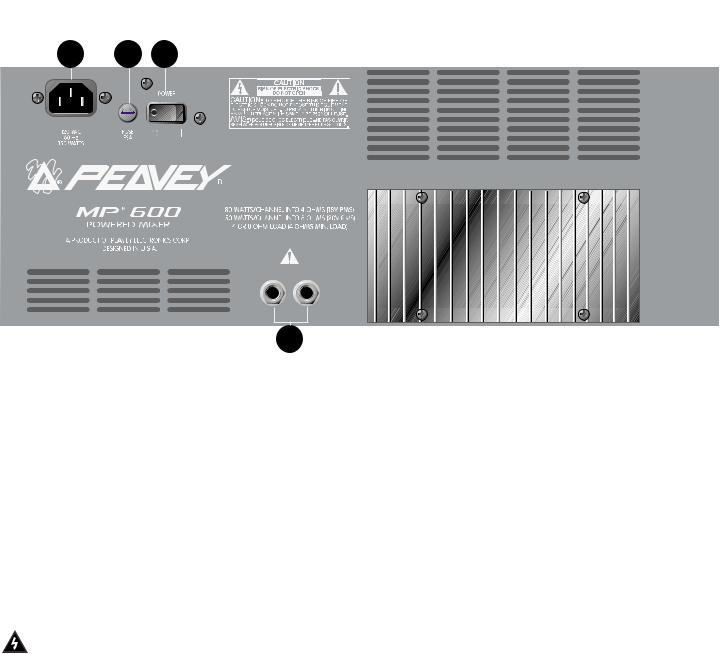
REAR PANEL
3
4
POWER
This section describes the proper application of AC power to your MP 600. To ensure the safety of you and your MP 600, please pay close attention to any designated cautions.
1.POWER SWITCH
Used to turn AC mains power on or off.
2.FUSE
The fuse is located within the cap of the fuseholder. If the fuse should fail, IT MUST BE
REPLACED WITH THE SAME TYPE AND VALUE IN ORDER TO AVOID DAMAGE TO THE EQUIPMENT AND TO PREVENT VOIDING THE WARRANTY. If the amp repeatedly blows fuses, it should be taken to a qualified service center for repair.
WARNING: THE FUSE SHOULD ONLY BE REPLACED WHEN THE POWER CORD HAS BEEN DISCONNECTED FROM ITS POWER SOURCE.
3.REMOVABLE AC POWER CORD
This receptacle is for the IEC line cord (included), which provides AC power to the unit. Connect the line cord to this connector and to a properly grounded AC supply. Damage to the equipment may occur if an improper line voltage is used. (See voltage marking on unit.) Never remove or cut the ground pin of the line cord plug. This unit is supplied with a properly rated line cord. When lost or damaged, replace this cord with one of the proper ratings.
(For UK Only) As the colours of the wires in the mains lead of this apparatus may not correspond with the coloured markings identifying the terminals in your plug, proceed as follows: • The wire which is coloured green and yellow must be connected to the terminal which is marked by the letter E or by the earth symbol, or coloured green or green and yellow. • The wire which is coloured blue must be connected to the terminal which is marked with the letter N or coloured black. • The wire which is coloured brown must be connected the terminal which is marked with the letter L or the coloured red.
4
SPEAKER CONNECTIONS
This section will help you locate the two speaker output jacks on the rear of your MP 600. Though there are two output jacks, they are mono (parallel) and not stereo. (2 — 8 ohms speakers)
WARNING: NEVER ALLOW YOUR TOTAL SPEAKER IMPEDANCE TO DROP BELOW THE INDICATED MINIMUM IMPEDANCE.
4.SPEAKER OUTPUTS
Two parallel 1/4" jacks are provided at the output of the power amplifier. Minimum speaker
impedance (minimum load) is 4 ohms.
.
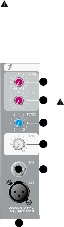
CHANNEL (1— 6) FEATURES
The following section describes Channels 1 — 6. Each of these input channels are identical. Some features listed below can be found on Channel 7 as well.
5.MIC INPUT
|
XLR balanced low impedance channel input optimized for a |
|
microphone or other low impedance source. Pin 2 is the positive |
10 |
input. This connector has +15V phantom power supply on pins 2 |
|
and 3 at all times. (Pin 1 is the ground reference.) |
|
WARNING: SOME PRODUCTS, INCLUDING SOME WIRELESS |
|
|
MICROPHONE UNITS, CAN BE DAMAGED BY PHANTOM |
|
|
POWER. CHECK THE OPERATING INSTRUCTIONS OF THE |
|
|
PRODUCT YOU WISH TO CONNECT TO THE MIC INPUT |
|
|
BEFORE CONNECTING. PHANTOM POWER DOESN’T |
|
|
AFFECT LOW IMPEDANCE DYNAMIC MICROPHONES. |
|
6. |
LINE INPUT |
|
|
1/4" unbalanced input that accepts line level sources equipped |
|
|
with a 1/4" plug (TS). The two inputs (XLR and 1/4") cannot be |
|
|
used simultaneously. |
|
7. |
GAIN |
|
|
Sets the level of the individual channel in the mix. |
|
8. |
REVERB |
|
|
Sets the level to internal reverb from channel and must be |
|
|
used in conjunction with the master reverb level. It is post gain and |
|
|
will be affected by the Gain adjustment (7). The Reverb control |
|
|
also determines the level of signal sent to the Effects Output (14). |
|
9. |
LOW EQ |
|
|
A shelving type of active tone control that varies the bass |
|
5 |
frequency levels ±15 dB at 100 Hz. It will add depth to thin signals, |
|
or clean up muddy ones. |
||
|
10.HIGH EQ
A shelving type of active tone control that varies the treble frequency level ±15 dB at 10 kHz. It is designed to remove noise or to add brilliance to the signal, depending on the quality of the source.
5
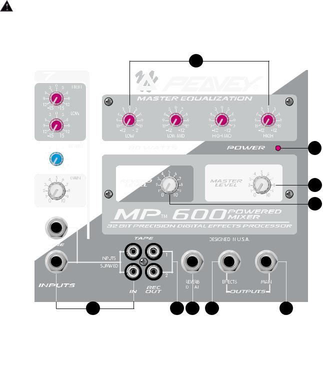
CHANNEL SEVEN FEATURES
Channel 7 has two 1/4" line inputs and RCA tape inputs. These inputs are summed. They add (sum) the left and right signals of a stereo source such as a tape or CD player.
11.LINE AND TAPE INPUTS
RCA and 1/4" jacks accept a stereo input from a CD player, tape deck or keyboard. These inputs are summed internally into a mono signal. See page 10 for operational note.
CAUTION: Care should be taken not to record on a deck that has its outputs connected to the line/tape input jacks and have the Channel 7 Gain control turned up, or Feedback will occur. You may disconnect the tape inputs on the MP 600 if recording on the same tapedeck. Or, you may use a separate tape deck to play and record at the same time.
19 |
18
16
17
11
MASTER FEATURES
12.TAPE [REC] OUTPUTS
RCA output jacks that provide a monaural signal the left and right inputs of a stereo tape deck. This is the main signal taken after the Master Level (16) and the Master EQ.
6

13.REVERB FOOTSWITCH
Provided for connection of the optional remote footswitch. The footswitch is used to activate/defeat the reverb. You may use the ON/OFF single-button switch #0051000.
14.EFFECTS OUTPUT
Plugging into this mono (TS) 1/4" output disconnects the internal reverb, allowing you to utilize external effects devices. In order to return the signal from the external effects unit, use the summing inputs of Channel 7.
OPERATION NOTE: When using Channel 7 as an effects return, it is important that you turn the Channel 7 Reverb control all the way down (“0” position). Failure to do so may cause oscillation or other strange effects. This is due to feeding signal returned from the effects loop back into the effects loop resulting in a feedback.
15.MAIN OUTPUT
1/4" unbalanced output that can be used as a source for an external amplifier/speaker system, feed to other mixers or a tape deck. This signal is taken after the master fourband equalizer.
16.MASTER LEVEL CONTROL
Controls the overall volume level of the system.
17.MASTER REVERB LEVEL CONTROL
Controls the amount of reverb that will be heard in the main mix.
18.POWER LED
Illuminates when AC power is being supplied to the mixer.
19.MASTER EQUALIZATION
Provides ±12 dB equalization at each center frequency. EQ boost is obtained by moving a particular EQ band’s control above the “0” position. EQ cut is obtained by moving a particular EQ band’s control below the “0” position. The following list describes each EQ control and its center frequency.
Low - shelving type - 40 Hz Low Mid - peak type - 300 Hz High Mid - peak type - 2 kHz High - shelving type - 10 kHz
OPERATION NOTE: This equalizer is designed to provide room equalization, feedback control and system tone control. No amount of equalization will correct the response curve of a poor loudspeaker. Always begin with all controls in the “0” position and avoid excessively boosting large segments of the audio passband, which could limit the system’s dynamic range.
7
MP™ 600
SPECIFICATIONS
NOTE: All specifications are typical unless otherwise noted.
0 dBV = 1 Volt RMS
0 dBu = .778 Volts RMS
All specs are referenced to nominal output level (0 dBv) unless otherwise noted.
All measurements are wideband 20 Hz to 20 kHz unless otherwise noted.
All control settings are nominal (50% rotation) unless otherwise noted.
CHANNEL:
Equivalent Input Noise:
-114 dBu @ 40 dB Max Gain
Frequency Response:
(To Speaker Outputs)
± 3 dB 20 Hz to 20 kHz
Distortion: @ (1 kHz)
Less than .009%
Input Impedance:
Low Z Bal. 2K ohms
1/4" Mic/Line Input 22K ohms
CHANNEL EQ:
High EQ:
± 15 dB @ 10 kHz Minimum Center Detent flat ±2 dB
Low EQ:
± 15 dB @ 100 Hz Minimum Center Detent flat ±2 dB
Nominal Channel Gain:
Line = 0 dB Low Z = 30 dB
Maximum Channel Gain:
Low Z = 50 dB
Line = 19 dB
Nominal Input Level:
Low Z = -28 dBu
Line = +2 dBu
Minimum Input Level:
Low Z = -48 dBu
Line = -17 dBu
Maximum Input Level:
Low Z = -9 dBu
Line = +30 dBu
Phantom Power:
+15 VDC
MASTER:
Gain:
Main: = 10 dB (variable)
High EQ:
± 12 dB @ 10 kHz Minimum Center Detent flat ±2 dB
High Mid EQ:
± 12 dB @ 2 kHz Minimum Center Detent flat ±2 dB
Low Mid EQ:
± 12 dB @ 300 kHz Minimum Center Detent flat ±2 dB
Low EQ:
± 12 dB @ 40 HZ Minimum Center Detent flat ±2 dB
Maximum Output Level:
Main: = + 20 dBu (8.0 V RMS)
Effects: = + 20 dBu (8.0 V RMS)
Nominal Headroom:
Main: = 18 dB
Effects: = 18 dB
Output Impedance:
Main: = 100 ohms Effects: = 100 ohms
Output Noise:
Residual: -93 dBu (Master Level Down)
Bus: -91 dBu
(Master Nominal, All Channel Level Full CCW, Reverb Level Down)
Nominal: -76 dBu
(All Controls Nominal, Low Z Input Terminated 150 Ohms)
Signal to noise ratio:
Microphone input to speaker output (>80 dB) Frequency Response: 20 Hz to 20 kHz
SYSTEM DYNAMIC RANGE:
95 dB
POWER AMP SECTION:
Frequency Response:
+0, -3 dB, 30 Hz to 28 kHz @ Rated Power
Rated Power and Load:
80 W RMS into 4 ohms
55 W RMS into 8 ohms
THD less than .5% Mic input to speaker output 1 kHz at rated power.
Speaker system Impedance: 4 ohms minimum.
Power Requirements:
150W @ 100V, 120V, 230 VAC 50/60 Hz
Specifications subject to change without notice.
8
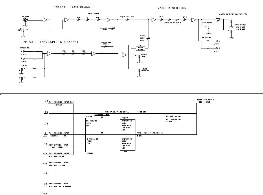
MP™ 600
LEVEL DIAGRAM
9
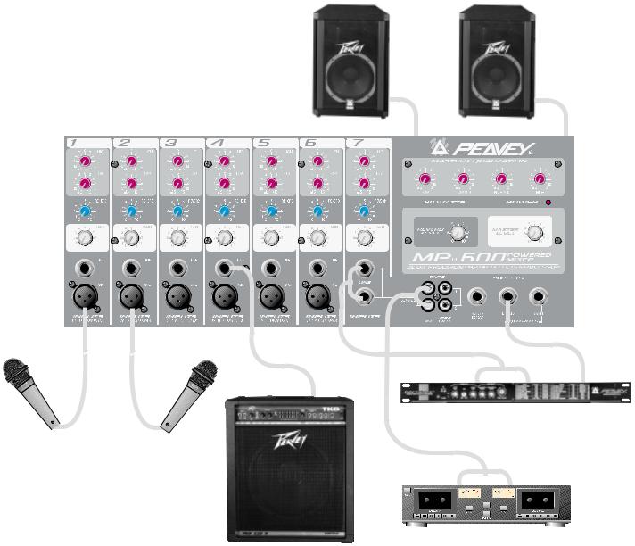
MP™ 600
HOOK UP DIAGRAM
112 TLS™
Outputs on back
Preamp out |
L |
Out |
R |
In |
|
|
|
|
Effects Unit
PVM® 22
L |
Out |
R |
Tape Deck*
TKO™ 115s
*Tape deck and Effects Unit should not be connected at the same time. Both are shown for demonstration purposes only.
10
 Loading...