


KB4/KB5 Keyboard Amplifier Owner Manual
For more information on other great Peavey products, go to your local Peavey dealer or online at www.peavey.com
Intended to alert the user to the presence of uninsulated “dangerous voltage” within the product’s enclosure that may be of sufficient magnitude to constitute a risk of electric shock to persons.
Intended to alert the user of the presence of important operating and maintenance (servicing) instructions in the literature accompanying the product.
CAUTION: Risk of electrical shock — DO NOT OPEN!
CAUTION: To reduce the risk of electric shock, do not remove cover. No user serviceable parts inside. Refer servicing to qualified service personnel.
WARNING: To prevent electrical shock or fire hazard, do not expose this appliance to rain or moisture. Before using this appliance, read the operating guide for further warnings.
Este símbolo tiene el propósito, de alertar al usuario de la presencia de “(voltaje) peligroso” sin aislamiento dentro de la caja del producto y que puede tener una magnitud suficiente como para constituir riesgo de descarga eléctrica.
Este símbolo tiene el propósito de alertar al usario de la presencia de instruccones importantes sobre la operación y mantenimiento en la información que viene con el producto.
PRECAUCION: Riesgo de descarga eléctrica ¡NO ABRIR!
PRECAUCION: Para disminuír el riesgo de descarga eléctrica, no abra la cubierta. No hay piezas útiles dentro. Deje todo mantenimiento en manos del personal técnico cualificado.
ADVERTENCIA: Para evitar descargas eléctricas o peligro de incendio, no deje expuesto a la lluvia o humedad este aparato Antes de usar este aparato, Iea más advertencias en la guía de operación.
Ce symbole est utilisé dans ce manuel pour indiquer à l’utilisateur la présence d’une tension dangereuse pouvant être d’amplitude suffisante pour constituer un risque de choc électrique.
Ce symbole est utilisé dans ce manuel pour indiquer à l’utilisateur qu’il ou qu’elle trouvera d’importantes instructions concernant l’utilisation et l’entretien de l’appareil dans le paragraphe signalé.
ATTENTION: Risques de choc électrique — NE PAS OUVRIR!
ATTENTION: Afin de réduire le risque de choc électrique, ne pas enlever le couvercle. Il ne se trouve à l’intérieur aucune pièce pouvant être reparée par l’utilisateur. Confiez I’entretien et la réparation de l’appareil à un réparateur Peavey agréé.
AVERTISSEMENT: Afin de prévenir les risques de décharge électrique ou de feu, n’exposez pas cet appareil à la pluie ou à l’humidité. Avant d’utiliser cet appareil, lisez attentivement les avertissements supplémentaires de ce manuel.
Dieses Symbol soll den Anwender vor unisolierten gefährlichen Spannungen innerhalb des Gehäuses warnen, die von Ausreichender Stärke sind, um einen elektrischen Schlag verursachen zu können.
Dieses Symbol soll den Benutzer auf wichtige Instruktionen in der Bedienungsanleitung aufmerksam machen, die Handhabung und Wartung des Produkts betreffen.
VORSICHT: Risiko — Elektrischer Schlag! Nicht öffnen!
VORSICHT: Um das Risiko eines elektrischen Schlages zu vermeiden, nicht die Abdeckung enfernen. Es befinden sich keine Teile darin, die vom Anwender repariert werden könnten. Reparaturen nur von qualifiziertem Fachpersonal durchführen lassen.
ACHTUNG: Um einen elektrischen Schlag oder Feuergefahr zu vermeiden, sollte dieses Gerät nicht dem Regen oder Feuchtigkeit ausgesetzt werden. Vor Inbetriebnahme unbedingt die Bedienungsanleitung lesen.

IMPORTANT SAFETY INSTRUCTIONS
WARNING: When using electrical products, basic cautions should always be followed, including the following:
1.Read these instructions.
2.Keep these instructions.
3.Heed all warnings.
4.Follow all instructions.
5.Do not use this apparatus near water.
6.Clean only with a dry cloth.
7.Do not block any of the ventilation openings. Install in accordance with manufacturer’s instructions.
8.Do not install near any heat sources such as radiators, heat registers, stoves or other apparatus (including amplifiers) that produce heat.
9.Do not defeat the safety purpose of the polarized or grounding-type plug. A polarized plug has two blades with one wider than the other. A grounding type plug has two blades and a third grounding plug. The wide blade or third prong is provided for your safety. If the provided plug does not fit into your outlet, consult an electrician for replacement of the obsolete outlet.
10.Protect the power cord from being walked on or pinched, particularly at plugs, convenience receptacles, and the point they exit from the apparatus.
11.Note for UK only: If the colors of the wires in the mains lead of this unit do not correspond with the terminals in your plug‚ proceed as follows:
a)The wire that is colored green and yellow must be connected to the terminal that is marked by the letter E‚ the earth symbol‚ colored green or colored green and yellow.
b)The wire that is colored blue must be connected to the terminal that is marked with the letter N or the color black.
c)The wire that is colored brown must be connected to the terminal that is marked with the letter L or the color red.
12.Only use attachments/accessories provided by the manufacturer.
13.Use only with a cart, stand, tripod, bracket, or table specified by the manufacturer, or sold with the apparatus. When a
cart is used, use caution when moving the cart/apparatus combination to avoid injury from tip-over.
14.Unplug this apparatus during lightning storms or when unused for long periods of time.
15.Refer all servicing to qualified service personnel. Servicing is required when the apparatus has been damaged in any way, such as power-supply cord or plug is damaged, liquid has been spilled or objects have fallen into the apparatus, the apparatus has been exposed to rain or moisture, does not operate normally, or has been dropped.
16.Never break off the ground pin. Write for our free booklet “Shock Hazard and Grounding.” Connect only to a power supply of the type marked on the unit adjacent to the power supply cord.
17.If this product is to be mounted in an equipment rack, rear support should be provided.
18.Exposure to extremely high noise levels may cause a permanent hearing loss. Individuals vary considerably in susceptibility to noise-induced hearing loss, but nearly everyone will lose some hearing if exposed to sufficiently intense noise for a sufficient time. The U.S. Government’s Occupational and Health Administration (OSHA) has specified the following permissible noise level exposures:
Duration Per Day In Hours |
Sound Level dBA, Slow Response |
8 |
90 |
6 |
92 |
4 |
95 |
3 |
97 |
2 |
100 |
1 1⁄2 |
102 |
1 |
105 |
1⁄2 |
110 |
1⁄4 or less |
115 |
According to OSHA, any exposure in excess of the above permissible limits could result in some hearing loss. Ear plugs or protectors to the ear canals or over the ears must be worn when operating this amplification system in order to prevent a permanent hearing loss, if exposure is in excess of the limits as set forth above. To ensure against potentially dangerous exposure to high sound pressure levels, it is recommended that all persons exposed to equipment capable of producing high sound pressure levels such as this amplification system be protected by hearing protectors while this unit is in operation.
SAVE THESE INSTRUCTIONS!

KB4/KB5
Keyboard Amplifiers
Thank you for selecting the KB4/KB5 keyboard players and put together an new KB Series amplifiers deliver awesome crystal highs—it’s all there!
Before you begin to play through your amp, supplied. You can find the proper voltage for unit. In addition, an external speaker jack is feature is located on the rear panel as well to the front and rear panel diagrams in this
Please read this guide carefully to ensure
ENGLISH
engineers have listened to input from
and sound in one portable package. The keyboard sounds—from thundering bass to
product has the proper AC line voltage line (power) cord on the rear panel of the
of an external speaker enclosure. This
. Each product feature is numbered. Refer features next to their number.
safety of your amplifier.
Features
·4-channel (KB4) or 5-channel (KB5)
·75 watts (KB4) or 150 watts (KB5)—plenty of
· ultra-strength‚ retractable‚ locking handle for |
it back and go! |
·balanced‚ stereo line outs
·stereo send/return jack
·extension speaker capability
QUICK SET-UP GUIDE
1.Connect the line cord to the appropriately rated receptacle
2.Be certain that all levels are down or set to the fully counter-clockwise position and set all the EQs flat
3.Set the master level to the 12:00 position
4.Connect left output of your keyboard to the left input of the KB5/KB4 and connect right output of your keyboard to the right input of the KB5/KB4
5.Set the DDT switch to the enable position
6.Set the main/monitor switch to the monitor position
7.Turn on power to the KB5/KB4
8.Adjust the channel level for proper volume
9.Adjust the channel EQ as needed
4
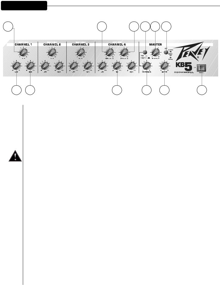
F R O N T P A N E L
4 |
5 |
7 |
9 |
11 |
6 |
8 |
10 |
12 |
1⁄4" jack input level. (Channels 1‚ 2 and 3 on the KB5 and channels 1 and 2 on the KB4.)
)
control (shelving type: +/-15dB) that varies the low frequency range. (KB5: channels 1‚ 2 & 1 & 2.)
Excessive low frequency boost causes greater power consumption and increases the of speaker damage.
control (shelving type: +/-15dB) that varies the hi frequency range. (KB5: channels 1‚ 2 & 3; 1 & 2.)
el (4)
high-impedance microphones or other high-level sources equipped with a 1⁄4" phone plug.
el (5)
low-impedance microphones or other low-level sources equipped with a male XLR connector.
)
control (peak/notch type: +/-15dB) that varies the mid frequencies. (Channel 4 on the KB5 3 on the KB4.)
itor (7)
what signal is sent to the headphones. When in the OUT position‚ only the signal from channel the headphones. Great when you need to hear a click track or midi/pre-recorded track. When position)‚ the headphones are sent signals from all channels. Keep in mind‚ this signal is
the Main XLR outs.
5
CH5/Monitor Level (8)
Controls the input level for channel 5. Controls high-impedance microphones or other high-level sources equipped with a 1/4" phone plug.
Headphone Level (9)
This sets the level to the headphone jack on the rear panel. To avoid damage to your hearing‚ make sure to turn the dial fully counter-clockwise before using headphones. Slowly turn the knob clockwise until a comfortable listening level is set. This does not affect the master level.
Master Level (10)
This knob sets the overall level for the unit. Make sure the Master level is completely down (full counterclockwise) before powering up the unit. This does not affect the headphone level.
DDT™ Selector (11)
This switch controls Peavey’s exclusive DDT (Distortion Detection Technique) speaker protection. With this switch in the OUT position‚ a unique circuit senses signal conditions that might overload the amplifier and activates compression to reduce gain and avoid clipping. This technique utilizes every watt available for the amplifier to reproduce the signal‚ yet minimizes clipping and distortion which reduces the potential for speaker damage. Since this function is “invisible” at levels below the clipping point‚ it is advised that it be activated at all times. Setting this switch to the IN position defeats this protection feature‚ allowing potential power amp clipping and the resultant increase in likelihood of speaker damage.
Power Switch (12)
This two-way rocker switch applies power to the unit when placed in the ON position.
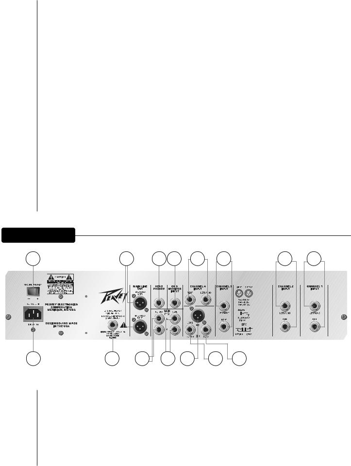
R E A R P A N E L
1 |
2 |
5 |
6 |
7 |
15 |
14 |
3 |
4 |
8 |
11 |
12 |
13 |
9 |
10 |
|
Ground Polarity (1)
This 3-position‚ rocker-type switch should normally be placed in the center (0) position. If hum or noise is noticed coming from the speaker enclosure‚ the switch may be placed in the (+) or (-) position to minimize hum/noise. If changing polarity does not alleviate the problem‚ consult your authorized Peavey dealer‚ the Peavey factory or a qualified service technician.
6

Main Line Out (2)
These low-noise‚ electronically balanced XLR connectors can be used to route signals to a mixing console‚ recording device‚ etc.
Send/Return Jacks Mains (3 & 4)
Two stereo pairs of 1/4" jacks allows the use of various auxiliary units (effects units‚ equalizers‚ etc.) in-line‚ before the power amp section.
Headphone Jack (5)
This 1/4" jack accepts stereo headphones only.
CH5/Monitor Input Jack (6)
Use this 1/4" jack to connect to the output of any line-level device.
Channel 4 (Channel 3 input on KB4) High-Impedance Input (7)
This pair of 1/4" jacks accepts high-impedance microphones or line-level sources equipped with left and right 1/4" phone plugs.
Channel 4 (Channel 3 input on KB4) Low-Impedance Input (8)
For use with low-impedance microphones or other line-level sources equipped with a male XLR connector.
Channel 4 (Channel 3 input on KB4) Send/Return Jack (9 & 10)
This pair of 1/4" jacks allows the use of various auxiliary units (effects units‚ equalizers‚ etc.) in-line.
Channel 3‚ 2 & 1 (Channel 2 & 1 on KB4) Inputs (11‚ 12 & 13)
This pair of 1/4" jacks accepts high-impedance microphones or line-level sources equipped with left and right 1/4" phone plugs.
External Speaker Jack (14)
This 1/4" jack provides the powered signal from the amplifier. Use this jack to add a second speaker cabinet in parallel. The external minimum speaker load impedance is 8 ohms.
IEC connector/detachable line cord (15)
This is a standard IEC power connector. An AC mains cord having the appropriate AC plug and ratings for the intended operating voltage is included in the carton. The mains cord should be connected to the amplifier before connecting to a suitable AC outlet.
U.S. Domestic AC Mains Cord
The mains cord supplied with the unit is heavy-duty‚ 3-conductor type with a conventional 120 VAC plug with ground pin. Never break off the ground pin on any equipment. It is provided for your safety. If the outlet used does not have a ground pin‚ a suitable grounding adapter should be used and the third wire should be properly grounded.
7
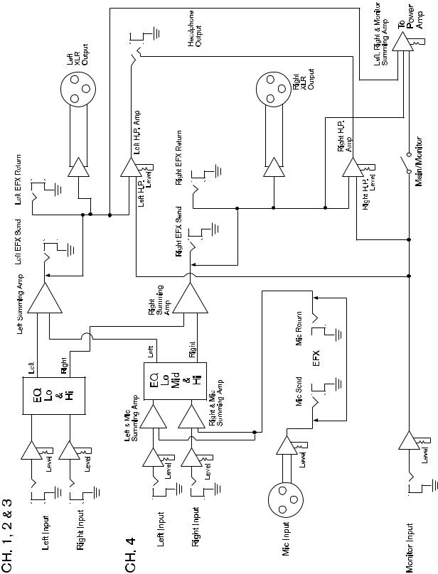
KB5 Block Diagram
8

KB5
SPECIFICATIONS
PREAMP SECTION
The following preamp specs are measured @ 1 kHz‚ nominal signal levels are with channel level controls set at 5‚ minimum levels are with channel level controls set at 10.
Channel 1‚ 2 and 3 inputs:
Input Impedance: 100K‚ Left/Mono Nominal Input Level: -22 dBV‚ 79 mV RMS Minimum Input Level: -40 dBV‚ 10 mV RMS Nominal Input Level: -15 dBV‚ 178 mV RMS Minimum Input Level: -33 dBV‚ 22 mV RMS
Channel 4 input:
Low Z Input Impedance: 5 k Ohms Nominal Input Level: -28 dBV‚ 40 mV RMS Minimum Input Level: -48 dBV‚ 4 mV RMS High Z Input Impedance: 100 l‚ Left Nominal Input Level: -5 dBV‚ 560 mV RMS Minimum Input Level: -22 dBV‚ 79 mV RMS
Right: -1 dBV‚ 1.1 V RMS
Minimum: -16 dBV‚ 158 mV RMS
Headphone output
Load Impedance: 8 Ohms or greater Nominal Output: 100 mW RMS
Main line out
Output Impedance: <100
Output Level: 18 dBV
POWER AMPLIFIER SECTION
Rated power and load:
200 Watts RMS/4 Ohms or 150 Watts RMS/8 Ohms with DDT off
(1 kHz, 1% THD @ 120 VAC line)
Frequency response:
+0, -1dB, 20Hz–20kHz @ 100 Watts RMS/ 8 Ohms
Total harmonic distortion:
Less than 0.01% @ 1 kHz/8 Ohms Typically less than 0.08%‚ 20 Hz–20kHz
DDT dynamic range:
Greater than 20 dB
DDT maximum THD:
Below 0.5% THD for 6 dB overload Below 1% THD for 20 dB overload
Hum and noise:
Greater than 100 dB below rated power
Power consumption:
300 Watts @ 120V AC‚ 50/60 Hz‚ domestic
300 Watts @ 220–230/240V AC‚ 60 Hz‚ export
PREAMP SECTION
The following preamp specs are measured @ 1 kHz‚ nominal signal levels are with channel level controls set at 5‚ minimum levels are with channel level controls set at 10.
Channel 1 and 2 Inputs:
Input Impedance: 100 k‚ Left/Mono Nominal Input Level: -22 dBV‚ 79 mV RMS Minimum Input Level: -40 dBV‚ 10 mV RMS Nominal Input Level: -15 dBV‚ 178 mV RMS Minimum Input Level: -33 dBV‚ 22 mV RMS
Channel 3 Input:
Low Z Input Impedance: 5K Ohms Nominal Input Level: -28 dBV‚ 40 mV RMS Minimum Input Level: -48 dBV‚ 4 mV RMS High Z Input Impedance: 100 k‚ Left Nominal Input Level: -5 dBV‚ 560 mV RMS Minimum Input Level: -22 dBV‚ 79 mV RMS
KB4
SPECIFICATIONS
Right: -1 dBV‚ 1.1 V RMS
Minimum: -16 dBV‚ 158 mV RMS
Headphone Output
Load Impedance: 8 Ohms or greater Nominal Output: 100 mW RMS
Main Line Out
Output Impedance: <100
Output Level: 18 dBV
POWER AMPLIFIER SECTION
Rated Power and Load:
100 Watts RMS/4 Ohms or 75 W RMS/8 Ohms with DDT off
(1 kHz, 1% THD @ 120 VAC line)
Frequency Response:
+0, -1dB, 20 Hz–20 kHz @ 60 Watts RMS/
8 Ohms
Total Harmonic Distortion:
Less than 0.01% @ 1 kHz/8 Ohms Typically less than 0.08%‚ 20 Hz–20kHz
DDT Dynamic Range:
Greater than 20 dB
DDT Maximum THD:
Below 0.5% THD for 6 dB overload Below 1% THD for 20 dB overload
Hum and Noise:
Greater than 100 dB below rated power
Power Consumption:
150 Watts @ 120V AC‚ 50/60 Hz‚ Domestic
150 Watts @ 220–230/240V AC‚ 60 Hz‚ Export
9
 Loading...