


invective.120
1
www.peavey.com
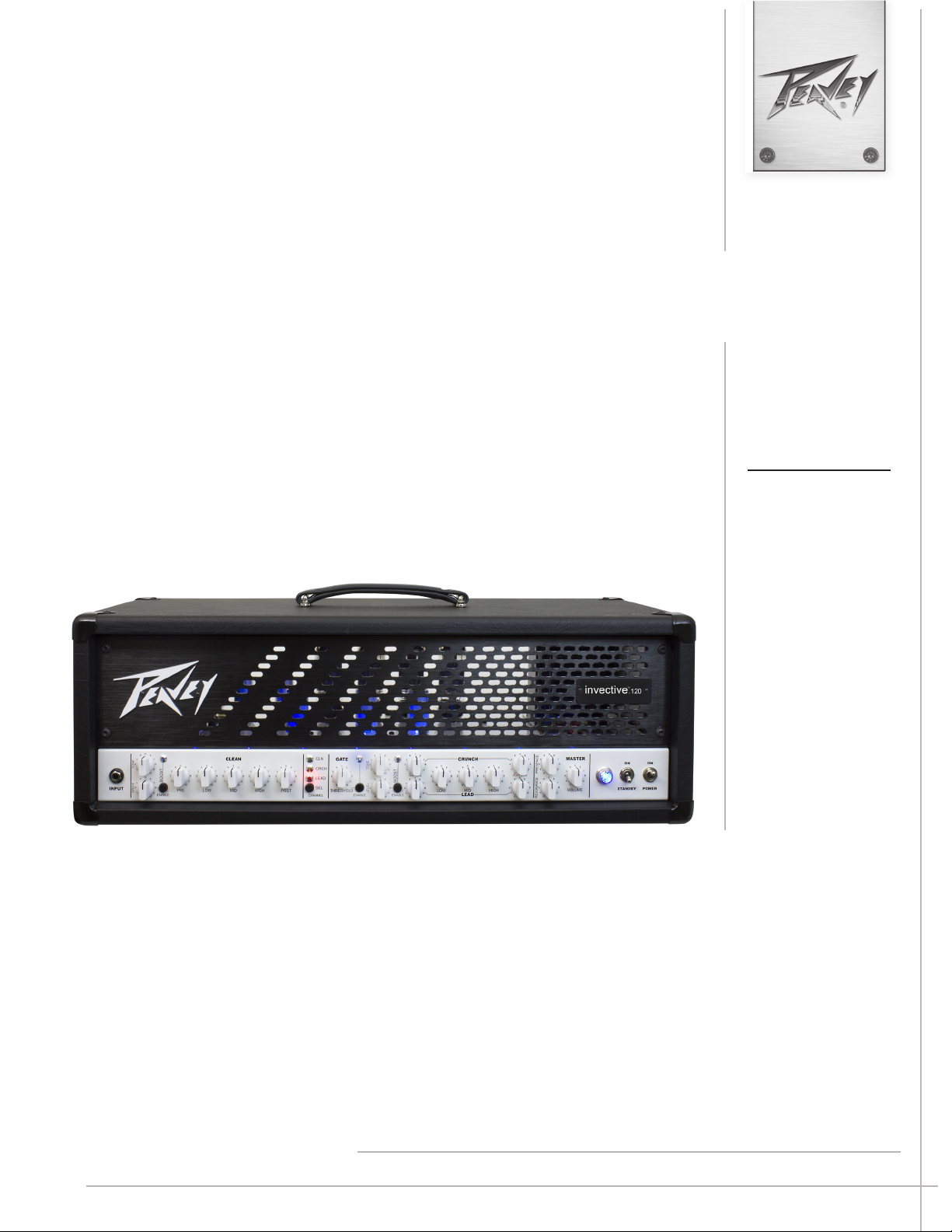
Invective™ 120
Amplier Head
Operating
Manual

2
FCC/ICES Compliancy Statement
This device complies with Part 15 of the FCC rules and Industry Canada license-exempt RSS Standard(s). Operation is
subject to the following two conditions: (1) this device may not cause harmful interference, and (2) this device must
accept any interference received, that may cause undesired operation.
Le présent appareil est conforme aux CNR d’lndustrie Canada applicables aux appareils radio exempts de
licence. L’exploitation est autorisée aux deux conditions suivantes: (1) I’appareil ne doit pas produire de
brouillage, et (2) I’utilisateur de I’appareil doit accepter tout brouillage radioélectrique subi, même si le
brouillage est susceptible d’en compromettre le fonctionnement.
Warning: Changes or modifications to the equipment not approved by Peavey Electronics Corp. can void the
user’s authority to use the equipment.
Note – This equipment has been tested and found to comply with the limits for a Class B digital device,
pursuant to Part 15 of the FCC Rules. These limits are designed to provide reasonable protection against
harmful interference in a residential installation. This equipment generates, uses, and can radiate radio
frequency energy and, if not installed and used in accordance with the instructions, may cause harmful
interference to radio communications. However, there is no guarantee that interference will not occur in a
particular installation. If this equipment does cause harmful interference to radio or television reception,
which can be determined by turning the equipment off and on, the user is encouraged to try and correct the
interference by one or more of the following measures.
• Reorient or relocate the receiving antenna.
• Increase the separation between the equipment and receiver.
• Connect the equipment into an outlet on a circuit different from that to which the receiver is
connected.
• Consult the dealer or an experienced radio/TV technician for help.
Caution
The equipment complies with FCC radiation exposure limits set forth for an uncontrolled
environment.

3
e new sound of metal is here. e Invective™ 120 is the culmination of nearly three decades of renements
and tweaks to Peavey’s legendary 6505 series with an all new clean channel and gobs of peripheral features that
are staples for today’s developing musical styles. Designed in close conjunction with Misha Mansoor, of Periph-
ery fame, the result is a monster of an amplier capable of accurately reproducing tons and tons of the sickest
tube amp tones imaginable….past, present, and future. ree separate channels (Clean/Crunch/Lead) and
two independent input boosts (one for clean, one for high gain channels) give you a sonic palette that lets your
imagination run wild. ere’s also a defeatable gate at the input of both gain channels designed to quickly mute
the input for a more “precise” muting characteristic. Capable of 120 Watts of earth shaking power, into the all-
new solid pine Invective 212 (or any standard guitar cabinet), this behemoth can blow the roof o the largest
of venues or….with a twist of the Master Volume and a ip of the half power switch, keep a crowd in the small-
est of clubs. Further tonal mayhem can be accomplished with outboard eects via the footswitchable Eects
Loops. e included 10-button MIDI footswitch allows for switching of all peripheral functions and storage of
presets. We’ve also included an internal MSDI direct analog recording/mic’d output and two auxiliary 9VDC
supply jacks for quick evaluation of pedals or to power a wireless setup. e all new Peavey® Invective™ 120….a
more than worthy successor to the legacy of Peavey’s high gain supremacy.
Features
• ree channels
• Preamp gain boost with gain and tone controls on Clean
• Preamp boost with level and tone controls on high gain channels
• Input gate on high gain channels
• Master Volume and Master Boost
• Resonance and Presence power amp damping controls
• MSDI direct out with level and tone controls
• Two Switchable eects loops
• Footswitch/MIDI In and MIDI Out jack
• Auxiliary 9VDC supplies
• 120W (rms) into 4, 8, or 16 Ohms (selectable impedance)
• Half power switch
• 10-button footswitch included
• Full set of current-based bias test points for easy troubleshooting
ENGLISH
4
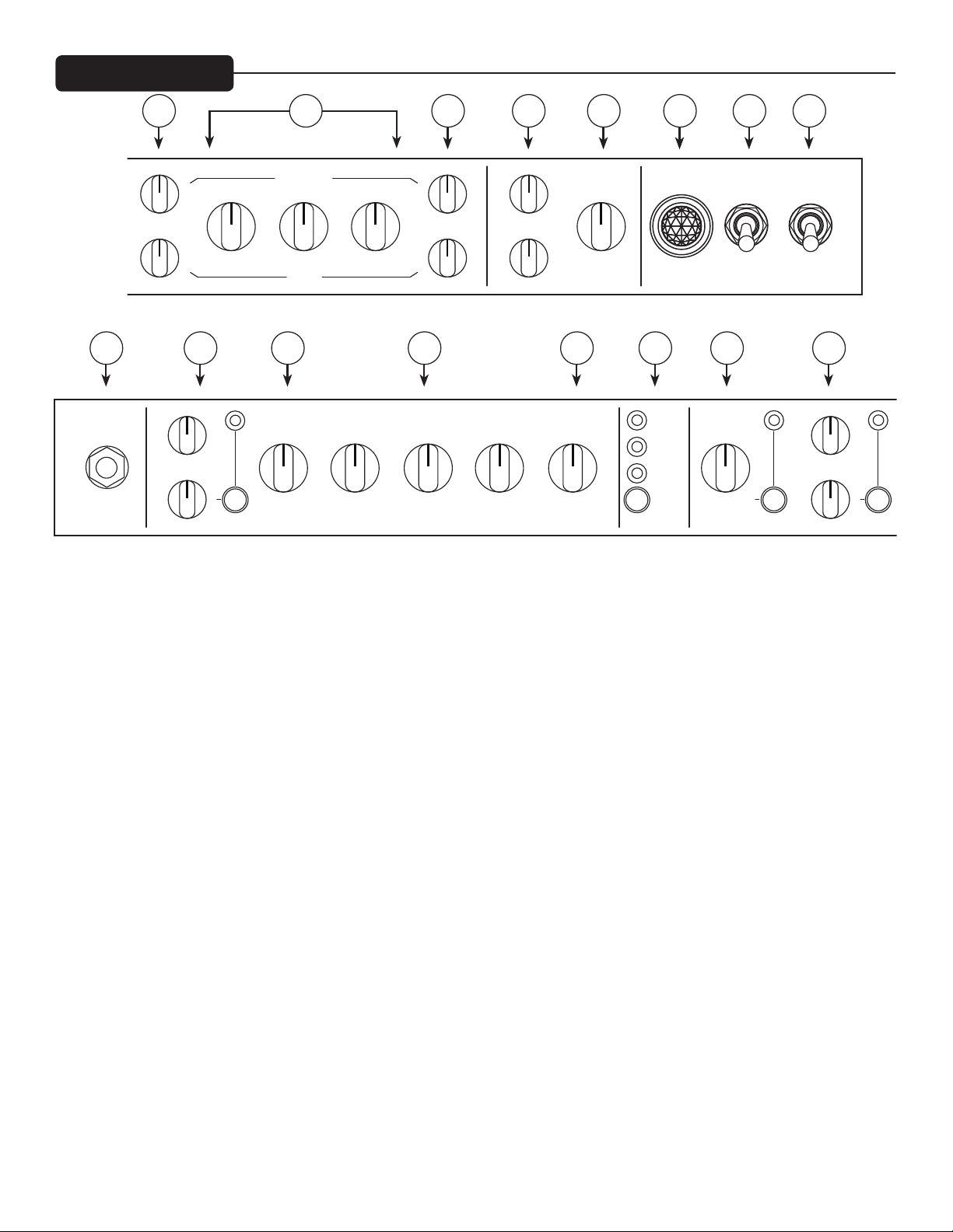
FRONT PANEL
(1) POWER SWITCH
Applies mains power to the unit. e red POWER STATUS LAMP (3) will illuminate when this switch is in the
ON position.
(2) STANDBY SWITCH
Engages the high voltage tube supply for immediate operation aer warm up.
TIP: Always allow for at least 5 minutes of warm up time before engaging the Standby switch. is will improve
performance and reliability of the power tubes.
(3) POWER STATUS LAMP
Illuminates when mains power is being supplied to the amp.
(4) MASTER VOLUME
Sets the overall volume level of the amp. Once the desired balance between the three channels in the amplier
has been achieved, the entire output level of the unit can be increased or decreased by rotating this control.
Note: this control is aer the eects loops in the signal path
(5) RESONANCE & PRESENCE
Allows for adjustment of the damping factor of the power amplier. Damping is the ability of an amplier to
control speaker cone motion aer the signal disappears. A higher damping factor reduces cone vibration more
quickly than a lower damping factor in the aected frequency range. e actual damping factor of the amplier
decreases as the knobs are turned up. Resonance works on the low end and Presence exclusively aects the high
end response of the power amp.
1
9
10111213141516
234568 7
CRUNCH
LEAD
POWERSTANDBY
ONON
MASTER
LOW MID VOLUMEHIGH
PRE GAIN POST GAIN
RESONANCE
PRESENCE
0 10
1 9
2 8
3 7
4
5
6
0 10
1 9
2 8
3 7
4
5
6
0 10
1 9
2 8
3 7
4
5
6
0 10
1 9
2 8
3 7
4
5
6
0 10
1 9
2 8
3 7
4
5
6
0 10
1 9
2 8
3 7
4
5
6
0 10
1 9
2 8
3 7
4
5
6
0 10
1 9
2 8
3 7
4
5
6
0 10
1 9
2 8
3 7
4
5
6
0 10
1 9
2 8
3 7
4
5
6
CLEAN GATE
INPUT
PRE LOW MID
SEL
CHANNEL
CLN
CRCH
LEAD
HIGH
LOW MID VOLUMEHIGH
ENABLE ENABLE
ENABLE
POST
THRESHOLD
BOOST
DRIVE TONE
ENABLE
LEVEL TONE
BOOST
PRE GAIN POST GAIN
0 10
1 9
2 8
3 7
4
5
6
0 10
1 9
2 8
3 7
4
5
6
0 10
1 9
2 8
3 7
4
5
6
0 10
1 9
2 8
3 7
4
5
6
0 10
1 9
2 8
3 7
4
5
6
0 10
1 9
2 8
3 7
4
5
6
0 10
1 9
2 8
3 7
4
5
6
0 10
1 9
2 8
3 7
4
5
6
0 10
1 9
2 8
3 7
4
5
6
0 10
1 9
2 8
3 7
4
5
6
0 10
1 9
2 8
3 7
4
5
6
0 10
1 9
2 8
3 7
4
5
6
0 10
1 9
2 8
3 7
4
5

5
(6) POST GAIN
is control, on the CRUNCH and LEAD channels, sets the overall level of its respective channel.
(7) LOW, MID, and HIGH EQ
ese passive controls, on both the Crunch and Lead channels, provide the signature tone print of the Invective
120.
(8) PRE GAIN
is control, on both the Crunch and Lead channels, controls the input volume level/gain of its respective chan-
nel. is control will increase the amount of preamp distortion and sustain.
(9) BOOST SECTION
is group of controls dictates the sound of the switchable BOOST section of the CRUNCH and LEAD chan-
nels. is is an input volume boost which pushes the high gain section of the amp to work against the gate for
maximum edge.
(10) GATE THRESHOLD
Turning up this switchable control, on both the CRUNCH and LEAD channels, controls the level at which the
input gate triggers to mute the incoming signal.
(11) CHANNEL
is momentary switch allows selection between the three channels. CHANNEL ACTIVATION LEDs indicate
which channel is active. Channel switching can also be accomplished from the included footswitch.
(12) VOLUME
is control, on the CLEAN channel, sets the overall level going to the power amp.
(13) LOW, MID, and HIGH EQ
ese passive controls provide the desired EQ curve for this channel.
(14) PRE
is knob controls the input sensitivity of this channel.
(15) BOOST SECTION
is group of controls dictates the sound of the switchable BOOST section of the CLEAN channel. is is an
input gain boost which pushes the clean section of the amp into classic overdrive territory.
(16) INPUT
is ¼” jack is designed to accommodate signals from any electric guitar, with active or passive pickups.

6
171819202122
232425262728
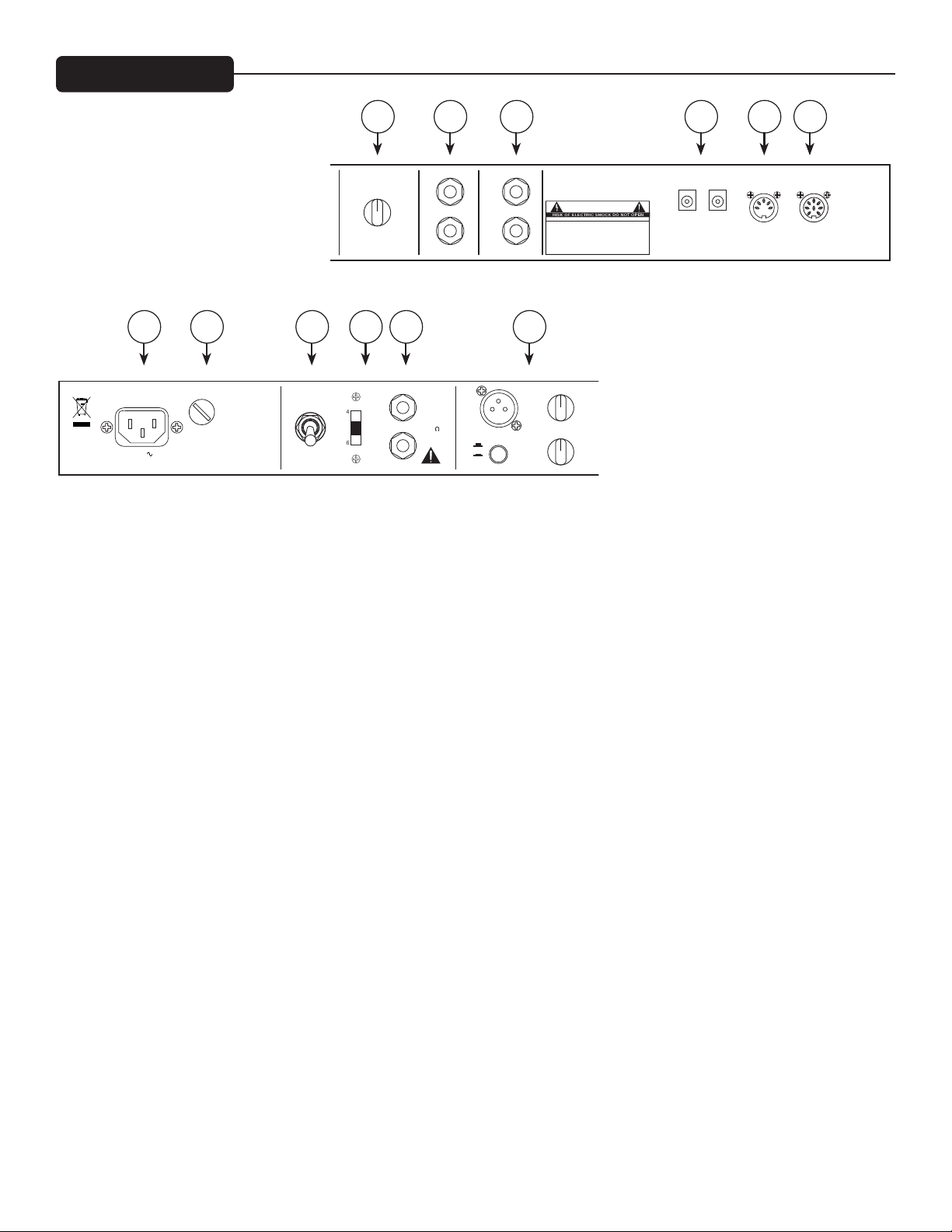
(17) MIDI IN/FOOTSWITCH
is 8-pin DIN connector is provided for the connection of the remote footcontroller. See the FOOTSWITCH
section of this manual for a more detailed explanation of operation. is can also be used as a MIDI IN connec-
tion, using a standard 5-pin MIDI cable, if the amp is going to be controlled by a separate MIDI controller other
than the supplied footcontroller. See the MIDI section of this manual for a more detailed explanation of the
MIDI features.
(18) MIDI OUT
is 5-pin DIN connector is provided to send MIDI messages, including Program Change and Continuous Con-
troller messages, to external MIDI devices. It is useful for linking two amps and keeping their functions synchro-
nized, and for sending your custom preset data to another amp or MIDI backup device. It’s also useful to control
presets on eects units you may have in the eects loops. See the MIDI section of this manual for a more detailed
explanation of the MIDI features.
(19) 9VDC AUX POWER SUPPLY
ese pedal-standard, 9VDC (negative tip) barrel jacks are provided for quick power connection to a variety of
pedals or other peripheral devices. Each jack is capable of providing up to 500mA of current.
(20 and 21) EFFECTS LOOPS
ese series loops are used to route the Invective 120 signal path through external eects devices or signal pro-
cessors.
Note: the loops are aer the master boost, but before the master volume in the signal path. is allows the master
boost to not boost/cut ambient eects trails.
(22) MASTER BOOST
is control sets the amount of footswitchable post-EQ volume boost available with a range of 0-5dBV.
Note: this control is before the eects loops in the signal path.
REAR PANEL
POWER
SUPPLY
MASTER BOOST
(NEGATIVE TIP)
RETURN
SEND
RETURN
FOOT-
SWITCH IN
OUT/
THRU
LEVEL
MIDI MIDI
CAUTION
WARNING:
APPARATUS SHOULD NOT BE EXPOSED TO RAIN OR MOISTURE AND
HAZARD, REPLACE WITH SAME TYPE 250 VOLT FUSE.
TO REDUCE THE RISK OF FIRE OR ELECTRIC SHOCK, THIS
DANS LE BUT DE REDUIRE LES RISQUES D’INCENDIE OU DE
AVIS:
A LA PLUIE OU A L’HUMIDITE ET AUCUN OBJET REMPLI DE LIQUIDE,
DECHARGE ELECTRIQUE, CET APPAREIL NE DOIT PAS ETRE EXPOSE
TEL QU’UN VASE, NE DOIT ETRE POSE SUR CELUI-CI. REMPLACER
PAR UN FUSIBLE DE MEME TYPE ET DE 250 VOLTS.
AVIS:
RISQUE DE CHOC ELECTRIQUE NE PAS OUVRIR
OBJECTS FILLED WITH LIQUIDS, SUCH AS VASES, SHOULD NOT
BE PLACED ON THIS APPARATUS. TO PREVENT THE RISK OF FIRE
SEND
ENGINEERED IN USA
DESIGNED AND
A PRODUCT OF PEAVEY
ELECTRONICS CORP.
www.peavey.com
9VDC @ 500mA
EFFECTS LOOP 1
EFFECTS LOOP 2
0 10
1 9
2 8
3 7
4
5
6
POWER
SUPPLY
4
16
8
32
FUSE
60 Hz
300 WATTS
MSDI
MASTER BOOST
(NEGATIVE TIP)
RETURN
SEND
RETURN
OUTPUT
MICROPHONE SIMULATED
DIRECT INTERFACE
LEVEL
IMPEDANCE
OUTPUT
POWER
FULL
FULL POWER
8 16
HALF
HALF POWER
LIFT
GROUND
LEVEL
TONE
SPEAKER OUTPUTS
44V RMS 4 MIN.
120W RMS/
SPEAKER JACKS PARALLELED
CLASS 2 WIRING
CAUTION
WARNING:
APPARATUS SHOULD NOT BE EXPOSED TO RAIN OR MOISTURE AND
HAZARD, REPLACE WITH SAME TYPE 250 VOLT FUSE.
TO REDUCE THE RISK OF FIRE OR ELECTRIC SHOCK, THIS
DANS LE BUT DE REDUIRE LES RISQUES D’INCENDIE OU DE
AVIS:
A LA PLUIE OU A L’HUMIDITE ET AUCUN OBJET REMPLI DE LIQUIDE,
DECHARGE ELECTRIQUE, CET APPAREIL NE DOIT PAS ETRE EXPOSE
TEL QU’UN VASE, NE DOIT ETRE POSE SUR CELUI-CI. REMPLACER
PAR UN FUSIBLE DE MEME TYPE ET DE 250 VOLTS.
AVIS:
RISQUE DE CHOC ELECTRIQUE NE PAS OUVRIR
OBJECTS FILLED WITH LIQUIDS, SUCH AS VASES, SHOULD NOT
BE PLACED ON THIS APPARATUS. TO PREVENT THE RISK OF FIRE
SEND
F5AL/250V
120V
Consumo de energia 300Wh
Consumo de energia
en modo de espera 92Wh
CAN-ICES-3(B)/NMB-3(B)
A PRODUCT OF PEAVEY
ELECTRONICS CORP.
www.peavey.com
9VDC @ 500mA
EFFECTS LOOP 1
EFFECTS LOOP 2
0 10
1 9
2 8
3 7
4
5
6
0 10
1 9
2 8
3 7
4
5
6
0 10
1 9
2 8
3 7
4
5
6

7
(23) MSDI SECTION
e proprietary Peavey MSDI circuit provides a balanced microphone-simulated direct signal to outboard
recording gear and mixers. e “microphone” compensation very accurately reproduces the sound of whatever
cab you are using in conjunction with the Invective 120. e LEVEL control adjusts the output level of the XLR
jack, the TONE control adjusts the extreme high frequency response of the output to accommodate dierent
high frequency drivers in PA systems, and the GROUND LIFT switch is used to break hum-inducing ground
loops between the Invective 120 and outboard equipment.
(24) SPEAKER OUTPUTS
Paralleled ¼” mono (TS) jacks are provided for the connection of speaker enclosure(s). e Impedance switch
should be set to match the load of the speaker cabinet(s), as described above. Always use good quality speaker
cables (not shielded instrument cable) for these connections.
(25) IMPEDANCE SELECTOR
ree-position switch allows for appropriate selection of speaker cabinet impedance. If two enclosures of equal
impedance are used, the switch should be set to half the individual value. For example, two 16 Ohm enclosures
necessitate an 8 Ohm setting, while two 8 Ohm enclosures would require a 4 Ohm setting. When using the amp
in HALF POWER mode, note that there is a 2:1 impedance dierence which is also listed near the switch.
(26) OUTPUT POWER
is switch sets the maximum power level to either Full or Half, is literally shuts o two of the four power
output tubes.
(27) AC MAINS FUSE
is fuse is for the mains supply for the amp. e fuse is located within the cap of the fuse holder. is fuse must
be replaced with one of the same type and value to avoid damaging the amplier and voiding the warranty. If the
amp repeatedly blows the fuse, it should be taken to a qualied service center for repair.
WARNING: THE FUSE SHOULD ONLY BE REPLACED AFTER THE POWER CORD HAS BEEN DIS-
CONNECTED.
(28) IEC MAINS CONNECTOR
is is a standard IEC power connector. An AC mains cord having the appropriate AC plug and ratings for the
intended operating voltage is included in the carton. e mains cord should be connected to the amplier before
connecting to a suitable AC outlet.
U.S. DOMESTIC AC MAINS CORD
e mains cord supplied with the unit is a heavy-duty, 3-conductor type with a conventional 120 VAC plug
with ground pin. If the outlet used does not have a ground pin, a suitable grounding adapter should be
used, and the third wire should be grounded properly.
Never break o the ground pin on any equipment. It is provided for your safety.
NOTE: FOR U.K. ONLY
If the colors of the wires in the mains lead of this unit do not correspond with the colored markings identi-
fying the terminals in your plug, proceed as follows: (1) e wire that is colored green and yellow must be
connected to the terminal that is marked by the letter E, the earth symbol, colored green, or colored green
and yellow. (2) e wire that is colored blue must be connected to the terminal that is marked with the letter
N or the color black. (3) e wire that is colored brown must be connected to the terminal that is marked
with the letter L or colored red.

8
TOP PANEL
12AX7A/ECC83 x 6
Preamp tubes. Tubes function as follows:
V1 = Crunch/Lead stages 1/2
V2 = Crunch/Lead stages 3/4
V3 = Loop driver/PI driver
V4 = Phase Inverter
V5 = Crunch/Lead stages 5/6
V6 = Clean channel
6L6GC x 4
Power tubes. Apart from 6L6GC, other types can be used including EL34, 6550, KT66, KT88 and 6CA7. When
replacing please use matched quartets of good quality tubes and ensure the biasing is set correctly as described
below. V7 and V9 are switched out of circuit in half power mode.
Please Note: Due to the high temperatures, do not attempt to replace any tubes unless the amplier has been
turned o for at least 15 minutes. is should only be carried out by a technically competent person.
(29) BIAS ADJUST
Adjusting this will vary the bias supply. is should only be adjusted by a qualied Peavey technician, otherwise
it could damage your tone, or worse, damage your power tubes.
(30) BIAS TEST POINTS
ese voltage test points are provided for technicians to use for quickly determining the plate current of each
power tube. Using a DC millivolt (mV) meter, one can measure voltage from the BIAS COMMON to the red
test point for a given tube. e resulting reading in mV is directly proportional to the plate current of that tube
(i.e.: 35mVDC = 35mA plate current). Optimum idle plate current for stock tubes is 26mA per tube.
WARNING: Removing the rear panel will expose the tubes. ese are VERY hot and touching them should be
avoided. is procedure should only be carried out by technically competent people and at their own risk.
29
V5 V2 V1 V6
V3V4
V7V8
V10
V9
30

9
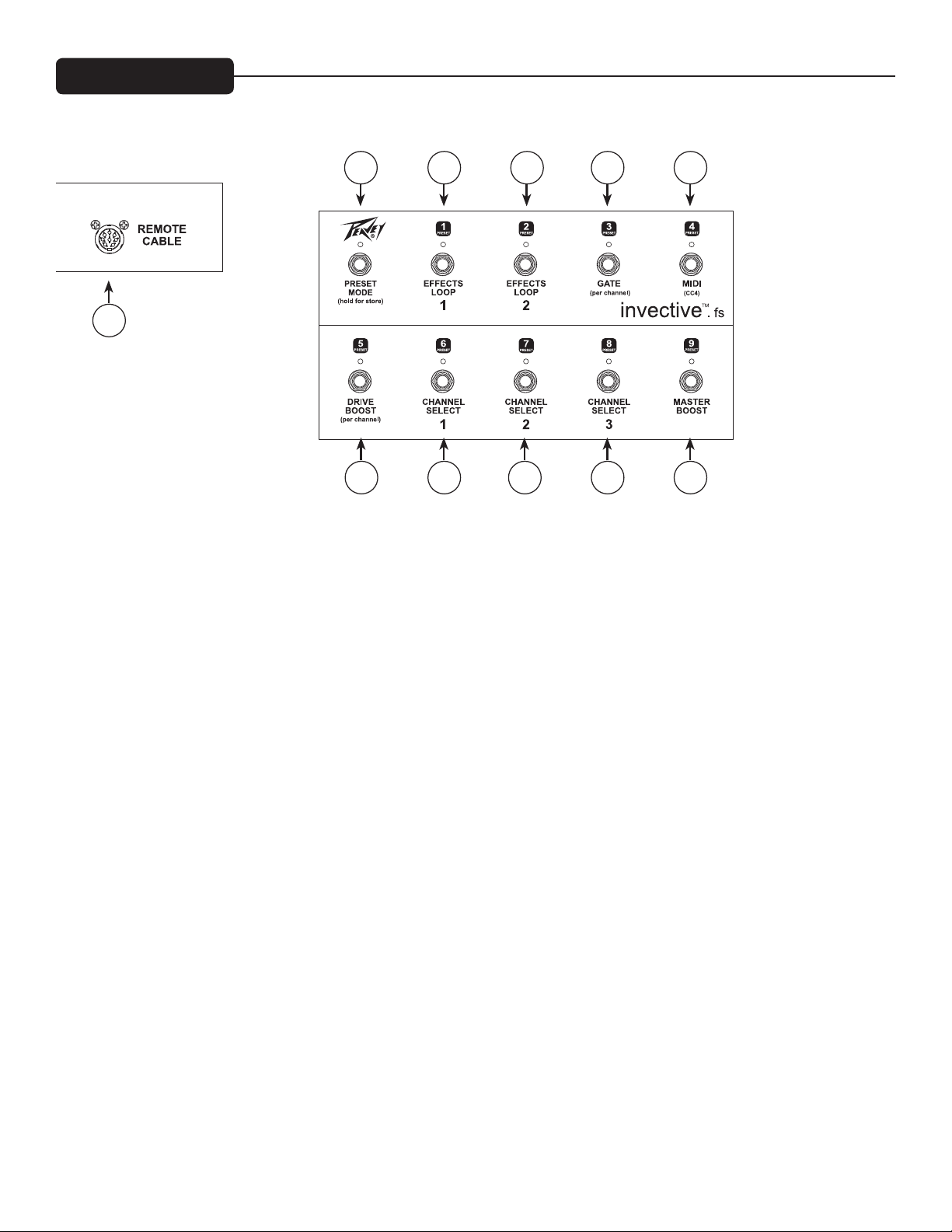
FOOTSWITCH
(31) Remote Cable
An eight-pin DIN connector is provided for connecting the footcontroller to the amplier IN/FOOT (38) via the
cable included in the carton.
(32) Preset Mode
Switches the footcontroller between NORMAL mode (default, LED o) and PRESET mode (LED red). Other
LEDs will be red for Preset Mode, and green for Normal Mode. (See “Using Preset Mode” section on pg. 10)
(33) Eects Loop 1 / Preset # 1
NORMAL mode: is turns on Eects Loop 1.
PRESET mode: is selects Preset 1. If selected, the LED will be lit red.
(34) Eects Loop 2 / Preset # 2
NORMAL mode: is turns on Eects Loop 2.
PRESET mode: is selects Preset 2. If selected, the LED will be red.
(35) Gate / Preset # 3
NORMAL mode: is turns on the gate circuit when using Channel 2 or 3.
PRESET mode: is selects Preset 3. If selected, the LED will be red.
(36) MIDI CC4 / Preset #4
NORMAL mode: is will send MIDI controller 4 with data 0 (LED o) or 127 (LED on) to control external
MIDI gear.
PRESET mode: is selects Preset 4. If selected, the LED will be red.
31
37 38 39 40 41
32 33 34 35 36

10
(37) Drive Boost / Preset #5
NORMAL mode: is turns Drive BOOST on and o for the current channel. When switching between chan-
nels, this will remember what the last setting was for each. e LED will be green when Drive BOOST is on.
PRESET mode: is selects Preset 5. If selected, the LED will be red.
(38) Channel Select 1 / Preset #6
NORMAL mode: is selects Channel 1. e LED will be lit GREEN. If pressed a 2nd time, the channel will
return to the previous setting. is allows quick changing between two channels using a single switch.
PRESET mode: is selects Preset 6. If selected, the LED will be red.
(39) Channel Select 2 / Preset #7
NORMAL mode: is selects Channel 2. e LED will be lit GREEN. If pressed a 2nd time, the channel will
return to the previous setting. is allows quick changing between two channels using a single switch.
PRESET mode: is selects Preset 7. If selected, the LED will be red.
(40) Channel Select 3 / Preset #8
NORMAL mode: is selects Channel 3. e LED will be lit GREEN. If pressed a 2nd time, the channel will
return to the previous setting. is allows quick changing between two channels using a single switch.
PRESET mode: is selects Preset 8. If selected, the LED will be red.
(41) Master Boost / Preset #9
NORMAL mode: is turns the Master Boost on and o. e LED will be lit green.
PRESET mode: is selects Preset 9. If selected, the LED will be red.
Each of the 9 presets remembers the current channel, drive boost on/o, gate on/o, CC4 on/o, eects loop on/
o and master boost on/o. Additionally, it remembers the drive boost and gate status of the inactive channels.
is way you can, for example, have a clean preset saved without drive boost, and know that when you switch to
Channel 2, drive boost will be on.
e amp comes from the factory with 9 default presets that you can modify at will. When the PRESET MODE
light is on, you can use the 9 other footswitches to recall those 9 presets. At any time you can switch to NOR-
MAL mode and make changes to that sound. is can be during a performance and not permanently stored, or
to edit a preset and store to one of the 9 settings.
To store the current settings into one of the 9 presets, you start by holding the PRESET MODE switch down for
a second or two, aer which the other LEDs will blink (except the one for the current preset which will be on
steady – a way to remind you of which preset you were working with). At this point you can press one of the 9
preset switches to store there, or press PRESET MODE again to cancel.
USING PRESET MODE
STORING PRESETS

11
You can initiate this from PRESET mode or from NORMAL mode. Aer the store (or cancel) it will return to the
mode you were in. So you can setup and store 9 presets without ever entering PRESET mode if you wish. It’s
typical to set up your sound in NORMAL mode, then store your creation to one of the presets.
As described below, when in preset mode, the 1-9 switches will recall your 9 custom presets. When you press the
switch of the preset that is already active, it will toggle the status of the Master Boost. is allows a quick way to
recall a preset for a solo and get it boosted very quickly (just hit the switch twice!). Otherwise, you’d have to hit it,
then toggle out of preset mode, then hit the Master Boost switch – tap dance! (Of course, you can save the preset
with the boost active, and then the 2nd press would disable the boost.) To make the Master Boost status visual
while in preset mode (red LEDs for mode/preset) the 9/Master Boost LED will blink green when the boost is en-
abled. (If on preset 9, the color will toggle between red and green to show preset number and Master Boost on).
You can connect the MIDI Out to the MIDI In of another Invective 120 to synchronize the two amps. With the
footswitch connected to the rst amp, any changes you make with the footswitch (or front panel) will be dupli-
cated on the 2nd amp – if the 2nd amp is on the same MIDI channel. See MIDI Program Section (pg. 13).
You can also link the MIDI from the amp (or from the 2nd amp) to an eects unit to synchronize presets. If the
eects unit can store presets, they can change automatically when you recall presets on the footswitch.
Whenever a preset is recalled, it sends that program change command, followed by the controller status of CC4
(0 or 127 based on the CC4 function) and the controller status of CC10 (0 or 127 based on the MASTER BOOST
function). is allows the MIDI eects unit to respond to those controllers to do things like turn a delay on/
o, etc. e other footswitches also send CC messages when pressed, but not at preset recall like the above two.
(MASTER BOOST sends CC9 AND CC10. CC9 to control another invective, CC10 synced at preset recall for
MIDI control of other devices.) See MIDI section for CC numbers generated by each function.
QUICK BOOST
LINKING TO ANOTHER AMP AND/OR EFFECTS UNITS WITH THE MIDI OUT

12
MIDI IMPLEMENTATION
is amp is designed to be extremely functional with the included 10-button footswitch. e 8-pin footswitch
jack also works as a standard 5-pin MIDI input - to go along with the standard 5-pin MIDI output. ere are
times when the amp will be run with other types of MIDI foot controllers, a PC in the studio, or by an automated
rack rig - or linked to another Invective via MIDI. is is the information you need to mate this amp with other
MIDI devices.
NOTE: e MIDI Out will send data to another Invective (for function sync), to a PC (for 2-way communica-
tion during remote control or preset dump), or to an eects unit in the eects loop. is jack does not act like an
Out/ru. Data received at the MIDI In doesn’t result in data on the MIDI Out unless it was a valid message for
this amp.
MIDI CC: MIDI Continuous Controllers are used to change one function at a time. Aer selecting a preset
(see below), modications to that preset can be done with these messages. Making these changes on the amp or
footswitch generates these CC messages at the MIDI out.
Bn CC# data where n=chan-1 Data: any
(Decimal) (Hex)
1 01h Select chan 1
2 02h Select chan 2
3 03h Select chan 3
Data: 00h-3Fh Data: 40h-7Fh
4 04h * *
* Amp doesn’t respond to this, but it sends it based on preset/CC4 footswitch for controlling external MIDI gear.
5 05h Drive Boost 1 OFF Drive Boost 1 ON
6 06h Drive Boost 2 OFF Drive Boost 2 ON
7 07h Drive Boost 3 OFF Drive Boost 3 ON
8 08h Drive Boost OFF Drive Boost ON (active channel)
9 09h ** **
** Amp doesn’t respond to this, but it sends it based on preset/Master Boost footswitch for controlling external
MIDI gear.
10 0Ah Master Boost OFF Master Boost ON
11 0Bh FX Loop 1 OFF FX Loop 1 ON
12 0Ch FX Loop 2 OFF FX Loop 2 ON
13 0Dh Gate 2 OFF Gate 2 ON
14 0Eh Gate 3 OFF Gate 3 ON
15 0Fh Gate OFF Gate ON (active chan, 2 or 3)
Example: B0 0A 7F enables master boost (MIDI chan 1)

13
MIDI Program Changes are used to recall presets. Typically a preset will recongure all functions on the amp at
one time. (Programs 9-11 below are exceptions as they only aect the channel.)
NOTE: ese messages when recevied will be echoed to the MIDI Out jack for sync’ing with another Invective.
NOTE: e rst nine presets are your custom presets. ey recall whatever you store with the footswitch.
MIDI PROGRAM
CHANNEL DRIVE BOOST MASTER BOOST CC 4 GATE FX LOOP 1 FX LOOP 2
Cn data where n=chan-1 (preset saves for (preset saves for
(Decimal) (Hex) ...all three channels) ...channels 2 & 3)
0 00h <----------------------------------------preset 1--------------------------------------------------------->
1 01h <----------------------------------------preset 2--------------------------------------------------------->
2 02h <----------------------------------------preset 3--------------------------------------------------------->
3 03h <----------------------------------------preset 4--------------------------------------------------------->
4 04h <----------------------------------------preset 5--------------------------------------------------------->
5 05h <----------------------------------------preset 6--------------------------------------------------------->
6 06h <----------------------------------------preset 7--------------------------------------------------------->
7 07h <----------------------------------------preset 8--------------------------------------------------------->
8 08h <----------------------------------------preset 9--------------------------------------------------------->
Example: C0 00 recalls rst preset (MIDI chan 1)
Channel only:
9 09h 1 no change no change no change no change no change no change
10 0Ah 2 no change no change no change no change no change no change
11 0Bh 3 no change no change no change no change no change no change
e Factory Map is basically a long list of xed presets with every combination of function. If automating a per-
formance from a MIDI rig, any combination of these functions can be found in this binary-style table.
NOTE: Due to MIDI limitations, the CC4 function is only controlled by the custom presets, not by the Factory
Map. It will be unchanged, not cleared.
Factory Map: CHANNEL DRIVE BOOST MASTER BOOST GATE FX LOOP 1 FX LOOP 2
(decimal) (hex)
12 0Ch 1 n/a
13 0Dh 2
14 0Eh 3
15 0Fh 1 X n/a
16 10h 2 X
17 11h 3 X
18 12h 1 X n/a
19 13h 2 X
20 14h 3 X
21 15h 1 X X n/a
22 16h 2 X X
23 17h 3 X X
24 18h 1 n/a
25 19h 2 X
blank = OFF; X = ON; n/a = not applicable

14
Factory Map: CHANNEL DRIVE BOOST MASTER BOOST GATE FX LOOP 1 FX LOOP 2
(decimal) (hex)
26 1Ah 3 X
27 1Bh 1 X n/a
28 1Ch 2 X X
29 1Dh 3 X
30 1Eh 1 X X n/a
31 1Fh 2 X X X
32 20h 3 X X X
33 21h 1 X X n/a
34 22h 2 X X X
35 23h 3 X X X
36 24h 1 n/a X
37 25h 2 X
38 26h 3 X
39 27h 1 X n/a X
40 28h 2 X X
41 29h 3 X X
42 2Ah 1 X n/a X
43 2Bh 2 X X
44 2Ch 3 X X
45 2Dh 1 X X n/a X
46 2Eh 2 X X X
47 2Fh 3 X X X
48 30h 1 n/a X
49 31h 2 X X
50 32h 3 X X
51 33h 1 X n/a X
52 34h 2 X X X
53 35h 3 X X X
54 36h 1 X n/a X
55 37h 2 X X X
56 38h 3 X X X
57 39h 1 X X n/a X
58 3Ah 2 X X X X
59 3Bh 3 X X X X
60 3Ch 1 n/a X
61 3Dh 2 X
62 3Eh 3 X
63 3Fh 1 X n/a X
64 40h 2 X X
65 41h 3 X X
66 42h 1 X n/a X
67 43h 2 X X
68 44h 3 X X
69 45h 1 X X n/a X
70 46h 2 X X X
71 47h 3 X X X
72 48h 1 n/a X
73 49h 2 X X

15
Factory Map: CHANNEL DRIVE BOOST MASTER BOOST GATE FX LOOP 1 FX LOOP 2
(decimal) (hex)
74 4Ah 3 X X
75 4Bh 1 X n/a X
76 4Ch 2 X X X
77 4Dh 3 X X X
78 4Eh 1 X n/a X
79 4Fh 2 X X X
80 50h 3 X X X
81 51h 1 X X n/a X
82 52h 2 X X X X
83 53h 3 X X X X
84 54h 1 n/a X X
85 55h 2 X X
86 56h 3 X X
87 57h 1 X n/a X X
88 58h 2 X X X
89 59h 3 X X X
90 5Ah 1 X n/a X X
91 5Bh 2 X X X
92 5Ch 3 X X X
93 5Dh 1 X X n/a X X
94 5Eh 2 X X X X
95 5Fh 3 X X X X
96 60h 1 n/a X X
97 61h 2 X X X
98 62h 3 X X X
99 63h 1 X n/a X X
100 64h 2 X X X X
101 65h 3 X X X X
102 66h 1 X n/a X X
103 67h 2 X X X X
104 68h 3 X X X X
105 69h 1 X X n/a X X
106 6Ah 2 X X X X X
107 6Bh 3 X X X X X

16
MIDI SYSEX
MIDI System Exclusive Commands are used to do all kinds of things that standard commands don’t handle.
e Invective uses Sysex for things like backing up or restoring the 9 user presets, or transferring them to a 2nd
amp.
NOTE: Except where noted below these messages when received will NOT be echoed to the MIDI Out jack.
BUT if the message does not have the matching MIDI channel of the rst amp, it WILL echo it in case the 2nd
amp matches.
9-preset dump
request: F0h 00h 00h 1Bh 16h MIDI chan - 1 00h F7h
(0-15) (no data)
When the amp receives this command, it will send a 9-preset dump message (see below) to the MIDI Out jack. If
connected to another Invective’s In jack (and that amp on same MIDI channel), the presets will be copied to that
amp. Connect the MIDI Out to a storage device to backup your 9 custom presets.
9-preset dump: F0h 00h 00h 1Bh 16h MIDI chan - 1 01h 36 nibbleized bytes F7h
(receive or send) (0-15) (presets 0-8)
When the amp receives this command, it will overwrite the 9 custom presets with the data in the command (9
presets x 4 nibbleized bytes) - and ECHO the dump in case there is a 2nd amp connected to the MIDI Out (and
on the same MIDI channel). e amp will SEND this data if it receives the dump request above. Additionally,
this dump can be initiated manually by holding the Channel 1 Drive button and pressing the Channel Select
button.
current setting
dump request: F0h 00h 00h 1Bh 16h MIDI chan - 1 04h F7h
(0-15) (no data)
When the amp receives this command, it will send a current setting dump message (below) to the MIDI Out
jack. e main purpose is for a PC editor to get the current audible setting to sync its display with the amp. is
setting could be dierent from any of the 9 presets if has been modied in Stomp mode and not stored yet.
current setting
dump: F0h 00h 00h 1Bh 16h MIDI chan - 1 05h 4 nibbleized bytes F7h
(0-15) (current audible setting)
e amp will send this message when requested, but will ignore it if received. e current setting can be set easily
with controller or program change messages, so this method is not supported as an input message.
preset store: F0h 00h 00h 1Bh 16h MIDI chan - 1 06h preset # - 1 F7h
(0-15) (0-8)
When the amp receives this command, it will save the current audible preset to one of the 9 custom presets. e
audible preset could be modied via MIDI CC commands. Once the preset is satisfactory, it can be saved to one
of the 9 custom locations with this command. at would be the method of remote control with a PC, or for cre-
ating an editor/librarian application. Message is echoed in case there is a 2nd amp on the same channel.

17
NOTE: commands that send nibbleized preset data send HIGH byte/nibble, then LOW.
Preset Bit: 15 14 13 12 11 10 9 8 7 6 5 4 3 2 1 0
Denition: n/a gate gate eects loop 2, 1 n/a CTL 4 master boost 1 for chan 3 1 for chan 1 Overboost
1 = active 3 2 / CTL 9 0 for chan 1 or 2 0 for chan 2 or 3 ch. 3, 2, 1
(n/a if bit 3 active)
set MIDI channel default chan=1
via sysex: F0h 00h 00h 1Bh 16h don’t care 0Dh channel - 1 F7h
(<= 0x7F) (0-15)
via footswitch:
Hold the last footswitch (9/Master Boost) for 2 seconds to enter MIDI channel select mode. e LEDs on the 1-8
footswitches will blink. You can then choose MIDI channel 1-8 by pressing one of those. You can also press 9/
Master Boost again to cancel the operation.
Note: e amp will always respond to the footswitch, but the MIDI channel allows it to
selectively respond to standard MIDI messages from other devices.
PRESET FORMAT

18
Power Amplier Section:
Rated Power & Load:
120W(rms) into 16, 8, or 4 Ohms
Power @ Clipping:
(Typically @ 5% THD, 1kHz, 120VAC line)
130W(rms) into 16, 8, or 4 Ohms
(Bias must be reduced to measure)
Frequency Response:
+0, -3dB, 50Hz to 20kHz, @ 100W(rms) into 8 Ohms
Hum & Noise:
Greater than 78dB below rated power
Power Amp EQ:
Active Presence: +10dB @ 2kHz
Active Resonance: +10dB @ cabinet resonant frequency
Power Consumption:
400W 50/60Hz, 120VAC (Domestic)
Pre-amp Section:
e following specs are measured @ 1kHz with the controls preset as follows:
Low & High EQ @ 10
Mid EQ @ 0
Post Gains @ 10
Resonance & Presence @ 0dB
Nominal levels with Pre Gains @ 5
Minimum levels with Pre Gains @ 10
All Gain boosts OFF
Gate OFF
All loops ON
Master Boost ON
Preamp Input:
Impedance: Very High Z, 470K Ohms
LEAD CHANNEL:
Nominal Input Level: -80dBV, 0.1mV(rms)
Minimum Input Level: -92dBV, 0.025mV(rms)
CRUNCH CHANNEL:
Nominal Input Level: -50dBV, 3.0mV(rms)
Minimum Input Level: -66dBV, 1.4mV(rms)
Maximum Input Level: -16dBV, 45mV(rms)
CLEAN CHANNEL:
Nominal Input Level: -8.0dBV, 400mV(rms)
Minimum Input Level: -21dBV, 90mV(rms)
Maximum Input Level: 0.0dBV, 1.0V(rms)
Eects Send:
Load Impedance: 1k Ohms or greater
Nominal Output: -10dBV, 300mV(rms)
SPECIFICATIONS

19
Eects Return:
Impedance: Very High Z, 470K Ohms
Designed Level: -10dBV, 300mV(rms)
System Hum & Noise @ Nominal Level:
(Clean Channel; 20Hz to 20kHz unweighted)
Greater than 78dB below rated power
Equalization:
Custom Low, Mid & High passive type EQ
Auxiliary Power Supply Jacks (x2):
9V DC (negative tip) @ 500mA
Dimensions: 26.7” W x 11.8” D x 10.0” H (678mm W x 300mm D x 254mm H)
Weight: 48.3lbs (21.9kg)
NOTE: Specications are subject to change without notice.

1
www.peavey.com
Invective™ 120
Tête d'amplicateur
Mode
d’emploi

2
Voici le nouveau son du métal L’Invective™ 120 est l’aboutissement de près de trois décennies de réglages et
de rectications de la légendaire série 6505 de Peavey avec de tous nouveaux canaux clean et des fonctionna-
lités périphériques à foison qui sont la base pour les styles musicaux qui se développent d’aujourd’hui. Conçu
en étroite collaboration avec Misha Mansour, du célèbre Périphéry, le résultat est un monstre d’amplicateur
capable de reproduire avec précision des tonnes de tonalités d’amplis de tubes les plus dingues imaginables ....
passés, présents et futurs. Trois canaux distincts (Clean/Crunch/Lead) et deux Boosts d'entrée indépendants
(un pour Clean, un pour les canaux à gain élevé) vous donnent une palette sonore qui vous permet de donner
libre cours à votre imagination. Il y a aussi une porte désactivable à l’entrée des deux canaux de gain conçue
pour couper rapidement l’entrée pour une caractéristique de sourdine plus « précise ». Puissance séismique de
120 watts, dans le tout nouveau Invective 212 en pin massif (ou tout caisson de guitare standard), ce monstre
peut faire sauter le toit des plus grandes salles ou .... en modiant le volume principal et en basculant l’interrup-
teur de réduction de puissance de moitié, entretenir une foule dans le plus petit des clubs. Un chaos tonal sup-
plémentaire peut être accompli avec des eets extérieurs via les boucles d’eets de la pédale. La pédale MIDI à
10 boutons intégrée permet de commuter toutes les fonctions périphériques et la mémorisation des préréglages.
Nous avons également inclus une sortie de micro/enregistrement analogique directe MSDI et deux prises
d’alimentation auxiliaires 9VDC pour l’évaluation rapide des pédales ou pour alimenter une conguration sans
l. Le tout nouveau Invective™ 120 de Peavey® .... un successeur plus que digne à la suprématie de la conception
existante à gain élevé Peavey.
Caractéristiques
• Trois canaux
• Amplication de gain de préamplication avec commandes de gain et de tonalité sur Clean
• Amplication de préamplication avec commandes de tonalité sur canaux à gain élevé
• Porte d’entrée sur les canaux à gain élevé
• Volume Master et Boost Master
• Contrôles d’amortissement des amplicateurs de puissance Résonance et Présence
• Sortie directe MSDI avec commandes de niveau et de tonalité
• Deux boucles d’eets commutables
• Prise de sortie MIDI et d’entrée MIDI/pédalier
• Alimentations 9VDC auxiliaires
• 120 W (rms) en 4, 8 ou 16 ohms (impédance sélectionnable)
• Commutateur de réduction de puissance de moitié
• Pédalier à 10 boutons intégré
• Ensemble complet de points de test de polarisation basé sur le courant pour un dépannage facile
FRANÇAIS

3
PANNEAU AVANT
(1) INTERRUPTEUR MARCHE/ARRÊT
Met l’unité sous tension. Le VOYANT D’ÉTAT D’ALIMENTATION rouge (3) s’allume lorsque ce commutateur
est sur la position ON.
(2) INTERRUPTEUR STANDBY
Enclenche l’alimentation du tube haute tension pour un fonctionnement immédiat après la phase de préchauf-
fage.
CONSEIL : Laissez toujours au moins 5 minutes de temps de préchauage avant d’enclencher le commutateur de
mode Standby. Cela permettra d'améliorer les performances et la abilité des tubes de puissance.
(3) VOYANT D'ÉTAT D'ALIMENTATION
Il s’allume lorsque l’alimentation est fournie à l’ampli.
(4) MASTER VOLUME
Règle le niveau de volume général de l’ampli. Une fois que la balance désirée entre les trois canaux de l’ampli-
cateur a été réglée, le niveau de sortie totale de l’appareil peut être augmenté ou diminué en tournant cette com-
mande.
Remarque: cette commande se trouve après les boucles d’eets dans le chemin du signal
(5) RÉSONANCE & PRÉSENCE
Permet le réglage du facteur d’amortissement de l’amplicateur de puissance. L’amortissement est la capacité
d’un amplicateur à contrôler le mouvement conique du haut-parleur après la disparition du signal. Un facteur
d'amortissement plus élevé réduit la vibration conique plus rapidement qu'un facteur d'amortissement inférieur
dans la plage de fréquences aectée. Le facteur d’amortissement eectif de l’amplicateur diminue à mesure que
les boutons sont tournés vers le haut. La résonance fonctionne sur l'extrémité inférieure et la présence aecte
exclusivement la réponse d'extrémité supérieure de l'ampli de puissance.
1
9
10111213141516
234568 7
CRUNCH
LEAD
POWERSTANDBY
ONON
MASTER
LOW MID VOLUMEHIGH
PRE GAIN POST GAIN
RESONANCE
PRESENCE
0 10
1 9
2 8
3 7
4
5
6
0 10
1 9
2 8
3 7
4
5
6
0 10
1 9
2 8
3 7
4
5
6
0 10
1 9
2 8
3 7
4
5
6
0 10
1 9
2 8
3 7
4
5
6
0 10
1 9
2 8
3 7
4
5
6
0 10
1 9
2 8
3 7
4
5
6
0 10
1 9
2 8
3 7
4
5
6
0 10
1 9
2 8
3 7
4
5
6
0 10
1 9
2 8
3 7
4
5
6
CLEAN GATE
INPUT
PRE LOW MID
SEL
CHANNEL
CLN
CRCH
LEAD
HIGH
LOW MID VOLUMEHIGH
ENABLE ENABLE
ENABLE
POST
THRESHOLD
BOOST
DRIVE TONE
ENABLE
LEVEL TONE
BOOST
PRE GAIN POST GAIN
0 10
1 9
2 8
3 7
4
5
6
0 10
1 9
2 8
3 7
4
5
6
0 10
1 9
2 8
3 7
4
5
6
0 10
1 9
2 8
3 7
4
5
6
0 10
1 9
2 8
3 7
4
5
6
0 10
1 9
2 8
3 7
4
5
6
0 10
1 9
2 8
3 7
4
5
6
0 10
1 9
2 8
3 7
4
5
6
0 10
1 9
2 8
3 7
4
5
6
0 10
1 9
2 8
3 7
4
5
6
0 10
1 9
2 8
3 7
4
5
6
0 10
1 9
2 8
3 7
4
5
6
0 10
1 9
2 8
3 7
4
5

4
(6) POST-GAIN
Cette commande, sur les canaux CRUNCH et LEAD, règle le niveau global de son canal respectif.
(7) EG BASSES, MOYENNE ET AIGUS
Ces commandes passives, à la fois sur les canaux Crunch et Lead, fournissent l’empreinte de tonalité de signature
de l’Invective 120.
(8) PRÉ-GAIN
Cette commande, sur les canaux Crunch et Lead, règle le gain/niveau de volume d’entrée de son canal respectif.
Cette commande augmentera la quantité de distorsion et de sustain (durée de vibration) du préampli.
(9) SECTION BOOST
Ce groupe de commandes dicte le son de la section BOOST commutable des canaux CRUNCH et LEAD. C’est
un boost de volume d’entrée qui pousse la section de gain haut de l’ampli pour fonctionner contre la porte pour
un front maximum.
(10) SEUIL DE PORTE
Tournez vers le haut cette commande commutable, à la fois sur les canaux CRUNCH et LEAD, permet de
contrôler le niveau auquel la porte d’entrée se déclenche pour couper le signal entrant.
(11) CANAL
Ce commutateur momentané permet la sélection entre les trois canaux. Les LED D'ACTIVATION DE CANAL
indiquent quel canal est actif. La commutation de canaux peut également être exécutée depuis la pédale intégrée.
(12) VOLUME
Cette commande, sur le canal CLEAN, règle le niveau global allant vers l’ampli de puissance.
(13) EG BASSES, MOYENNE ET AIGUS
Ces commandes passives fournissent la courbe d’égalisation souhaitée pour ce canal.
(14) PRÉ
Ce bouton contrôle la sensibilité d’entrée de ce canal.
(15) SECTION BOOST
Ce groupe de commandes dicte le son de la section BOOST commutable du canal CLEAN. C'est un boost de
gain d'entrée qui pousse la section Clean de l'ampli en mode overdrive classique.
(16) ENTRÉE
Cette prise ¼" est conçue pour recevoir les signaux d'une guitare électrique, avec des micros actifs ou passifs.
5
171819202122
232425262728
(17) ENTREE MIDI/PÉDALE
Ce connecteur DIN à 8 broches est destiné à la connexion de la pédale de commande à distance. Voir la section
PEDALE de ce manuel pour une explication plus détaillée son fonctionnement. Il est également possible de l’uti-
liser en connexion MIDI IN en utilisant un câble MIDI standard à 5 broches, si l’amplicateur doit être contrôlé
par une commande MIDI spécique autre que la pédale. Voir la section MIDI de ce manuel pour une explication
plus détaillée des fonctions MIDI.
(18) SORTIE MIDI
Ce connecteur DIN à 5 broches est fourni pour envoyer des messages MIDI, y compris des messages de change-
ment de programme et de contrôleur continu, aux périphériques MIDI externes. Il est utile pour relier deux am-
plis et maintenir leurs fonctions synchronisées, et pour envoyer vos données préréglées personnalisées à un autre
ampli ou périphérique de sauvegarde MIDI. Il est également utile pour contrôler les préréglages sur les systèmes
d’eets que vous pouvez avoir dans les boucles d’eets. Voir la section MIDI de ce manuel pour une explication
plus détaillée des fonctions MIDI.
(19) ALIMENTATION AUX 9VDC
Ces prises cylindriques 9VDC (embout négatif) sont fournies pour une connexion rapide à une variété de pé-
dales ou d’autres périphériques. Chaque prise est capable de fournir jusqu’à 500 mA de courant.
(20 et 21) BOUCLES D’EFFETS
Ces boucles de série servent à acheminer le chemin du signal de l’Invective 120 par des systèmes d’eets externes
ou des processeurs de signaux.
Remarque : les boucles sont après le Master Boost, mais avant le Master Volume dans le chemin du signal. Cela
permet au Master Boost de ne pas amplier/couper les chemins d’eets ambiants.
(22) MASTER BOOST
Cette commande dénit la quantité de Boost de volume post-EG commutable par pédale disponible avec une
plage de 0 à 5 dBV.
Remarque: cette commande se trouve avant les boucles d’eets dans le chemin du signal.
PANNEAU ARRIÈRE
POWER
SUPPLY
MASTER BOOST
(NEGATIVE TIP)
RETURN
SEND
RETURN
FOOT-
SWITCH IN
OUT/
THRU
LEVEL
MIDI MIDI
CAUTION
WARNING:
APPARATUS SHOULD NOT BE EXPOSED TO RAIN OR MOISTURE AND
HAZARD, REPLACE WITH SAME TYPE 250 VOLT FUSE.
TO REDUCE THE RISK OF FIRE OR ELECTRIC SHOCK, THIS
DANS LE BUT DE REDUIRE LES RISQUES D’INCENDIE OU DE
AVIS:
A LA PLUIE OU A L’HUMIDITE ET AUCUN OBJET REMPLI DE LIQUIDE,
DECHARGE ELECTRIQUE, CET APPAREIL NE DOIT PAS ETRE EXPOSE
TEL QU’UN VASE, NE DOIT ETRE POSE SUR CELUI-CI. REMPLACER
PAR UN FUSIBLE DE MEME TYPE ET DE 250 VOLTS.
AVIS:
RISQUE DE CHOC ELECTRIQUE NE PAS OUVRIR
OBJECTS FILLED WITH LIQUIDS, SUCH AS VASES, SHOULD NOT
BE PLACED ON THIS APPARATUS. TO PREVENT THE RISK OF FIRE
SEND
ENGINEERED IN USA
DESIGNED AND
A PRODUCT OF PEAVEY
ELECTRONICS CORP.
www.peavey.com
9VDC @ 500mA
EFFECTS LOOP 1
EFFECTS LOOP 2
0 10
1 9
2 8
3 7
4
5
6
POWER
SUPPLY
4
16
8
32
FUSE
60 Hz
300 WATTS
MSDI
MASTER BOOST
(NEGATIVE TIP)
RETURN
SEND
RETURN
OUTPUT
MICROPHONE SIMULATED
DIRECT INTERFACE
LEVEL
IMPEDANCE
OUTPUT
POWER
FULL
FULL POWER
8 16
HALF
HALF POWER
LIFT
GROUND
LEVEL
TONE
SPEAKER OUTPUTS
44V RMS 4 MIN.
120W RMS/
SPEAKER JACKS PARALLELED
CLASS 2 WIRING
CAUTION
WARNING:
APPARATUS SHOULD NOT BE EXPOSED TO RAIN OR MOISTURE AND
HAZARD, REPLACE WITH SAME TYPE 250 VOLT FUSE.
TO REDUCE THE RISK OF FIRE OR ELECTRIC SHOCK, THIS
DANS LE BUT DE REDUIRE LES RISQUES D’INCENDIE OU DE
AVIS:
A LA PLUIE OU A L’HUMIDITE ET AUCUN OBJET REMPLI DE LIQUIDE,
DECHARGE ELECTRIQUE, CET APPAREIL NE DOIT PAS ETRE EXPOSE
TEL QU’UN VASE, NE DOIT ETRE POSE SUR CELUI-CI. REMPLACER
PAR UN FUSIBLE DE MEME TYPE ET DE 250 VOLTS.
AVIS:
RISQUE DE CHOC ELECTRIQUE NE PAS OUVRIR
OBJECTS FILLED WITH LIQUIDS, SUCH AS VASES, SHOULD NOT
BE PLACED ON THIS APPARATUS. TO PREVENT THE RISK OF FIRE
SEND
F5AL/250V
120V
Consumo de energia 300Wh
Consumo de energia
en modo de espera 92Wh
CAN-ICES-3(B)/NMB-3(B)
A PRODUCT OF PEAVEY
ELECTRONICS CORP.
www.peavey.com
9VDC @ 500mA
EFFECTS LOOP 1
EFFECTS LOOP 2
0 10
1 9
2 8
3 7
4
5
6
0 10
1 9
2 8
3 7
4
5
6
0 10
1 9
2 8
3 7
4
5
6

6
(23) SECTION MSDI
Le circuit MSDI exclusif de Peavey fournit un signal direct simulé par microphone à l’équipement d’enregistre-
ment externe et aux mixeurs. La compensation « microphone » reproduit très précisément le son de tout cab que
vous utilisez en conjonction avec l’Invective 120. La commande de NIVEAU règle le niveau de sortie de la prise
XLR, la commande de TONALITÉ règle la réponse d’extrême haute fréquence de la sortie pour s’adapter aux dif-
férents conducteurs à haute fréquence dans les systèmes de sonorisation, et le commutateur GROUND LIFT sert
pour casser les boucles de terre induisant le ronement entre l’Invective 120 et l’équipement externe.
(24) SORTIE DE HAUT-PARLEUR
Des prises parallèles ¼” mono (TS) sont prévues pour la connexion des enceintes de haut-parleurs. Le sélecteur
d'impédance doit être réglé pour correspondre à la charge de la ou des enceintes de haut-parleurs, comme décrit
ci-dessus. Utilisez toujours des câbles de haut-parleur de bonne qualité (pas de câble d’instrument blindé) pour
ces connexions.
(25) SÉLECTEUR D’IMPÉDANCE
Ce bouton à trois positions permet de sélectionner l’impédance appropriée pour l’enceinte de haut-parleur. Si
deux enceintes d’impédance égale sont utilisées, l’interrupteur doit être réglé sur la moitié de la valeur indivi-
duelle. Par exemple, deux enceintes de 16Ω nécessitent un réglage de 8Ω, alors que deux enceintes de 8Ω né-
cessitent un réglage de 4Ω. Lorsque vous utilisez l'ampli en mode HALF POWER, notez qu'il y a une diérence
d'impédance de 2:1 qui est également indiquée près de l'interrupteur.
(26) PUISSANCE DE SORTIE
Ce commutateur règle le niveau de puissance maximum sur Full (100%) ou Half (50 %). Cela coupe littéralement
deux des quatre tubes de sortie de puissance.
(27) FUSIBLE SECTEUR AC
Ce fusible sert pour l’alimentation secteur de l’ampli. Le fusible se situe dans le bouchon du porte-fusible. Ce
fusible doit être remplacé par un fusible de type et de valeur identiques pour éviter d'endommager l'amplicateur
et annuler la garantie. Si le fusible de l’ampli saute plusieurs fois, il faut l’apporter à un centre d’entretien agréé
pour le faire réparer.
AVERTISSEMENT: LE FUSIBLE NE DOIT ÊTRE PLACÉ QUE LORSQUE LE CORDON D’ALIMENTA-
TION A ÉTÉ DÉBRANCHÉ DE SA SOURCE D’ALIMENTATION.
(28) CONNECTEUR SECTEUR IEC
C'est un connecteur d'alimentation standard IEC. Un cordon d'alimentation secteur avec les prises secteur ap-
propriées et de puissance adéquate aux tensions prévues de fonctionnement est inclus dans le carton. Le cordon
d’alimentation secteur doit d’abord être connecté à l’amplicateur avec d’être branché à une prise AC adaptée.
CORDON D’ALIMENTATION DOMESTIQUE AC AUX ÉTATS-UNIS
Le cordon de secteur fourni avec l’unité est de type à trois ls et de grande résistance, il est muni d’une prise
conventionnelle 120VAC avec une broche de mise à la terre. Si la prise de courant est dépourvue de broche
de terre, un adaptateur de mise à la terre approprié doit être utilisé et le troisième l doit être mis à la terre
convenablement.
Veillez à ne jamais casser la broche de terre sur tous appareils. Ce dispositif est prévu pour votre sécurité.
NOTE: FOR U.K. ONLY
If the colors of the wires in the mains lead of this unit do not correspond with the colored markings iden-
tifying the terminals in your plug, proceed as follows: (1) e wire that is colored green and yellow must be
connected to the terminal that is marked by the letter E, the earth symbol, colored green, or colored green
and yellow. (2) e wire that is colored blue must be connected to the terminal that is marked with the letter
N or the color black. (3) e wire that is colored brown must be connected to the terminal that is marked
with the letter L or colored red.

7
PANNEAU DU HAUT
12AX7A/ECC83 x 6
Tubes de préampli. Les tubes fonctionnent comme suit :
V1 = Phases Crunch/Lead 1/2
V2 = Phases Crunch/Lead 3/4
V3 = Conducteur de boucle/Conducteur PI
V4 = Onduleur de phase
V5 = Phases Crunch/Lead 5/6
V6 = Canal Clean
6L6GC x 4
Tubes de puissance. A part le 6L6GC, d’autres types peuvent être employés dont EL34, 6550, KT66, KT88 et
6CA7. Lorsque vous les remplacez utilisez des quartets adaptés de tubes de bonne qualité et assurez-vous que la
polarisation est réglée correctement, comme décrit ci-dessous. V7 et V9 sont désactivés du circuit en mode Half
Power.
Remarque : En raison des températures élevées, n’essayez pas de remplacer les tubes à moins que l’amplicateur
ne soit éteint depuis au moins 15 minutes. Cela ne doit être eectué que par une personne techniquement quali-
ée.
(29) RÉGLAGE DE LA POLARISATION
Ce réglage peut modier l’alimentation de polarisation. Il ne doit être réglé que par un technicien Peavey qualié,
autrement cela pourrait endommager votre tonalité, ou pire, endommager vos tubes de puissance.
(30) POINTS DE TEST DE POLARISATION
Ces points de test de tension sont mis à disposition des techniciens pour déterminer rapidement le courant de
plaque de chaque tube de puissance. À l’aide d’un compteur DC millivolts (mV), on peut mesurer la tension du
COMMUN DE POLARISATION au point de test rouge pour un tube. La lecture résultante en mV est directe-
ment proportionnelle au courant de plaque de ce tube (c.-à-d. : 35 mVDC = 35 mA de courant de plaque). Le
courant de plaque de repos optimum pour les tubes de stock est de 26 mA par tube.
AVERTISSEMENT: Le retrait du panneau arrière exposera les tubes. Ils sont TRÈS chauds et il faut éviter de
les toucher. Cette procédure ne doit être exécutée que par des personnes techniquement compétents et à leurs
propres risques.
29
V5 V2 V1 V6
V3V4
V7V8
V10
V9
30
8
PÉDALE
(31) Câble de télécommande
Un connecteur DIN à huit broches est prévu pour raccorder la commande à pédale de l’amplicateur IN/FOOT
(38) via le câble inclus dans le carton.
(32) Mode Preset (préréglé)
Commute la commande à pédale entre le mode NORMAL (par défaut, LED éteinte) et le mode PRESET (LED
rouge). D’autres LED seront rouges pour le mode Preset (Préréglé) et vert pour le mode normal. (Voir la section
« Utilisation du mode Preset » à la page 10)
(33) Boucle d’eets 1 / Préréglage N° 1
Mode NORMAL : Cela active la boucle d’eets 1.
Mode PRESET : Cela permet de sélectionner le Préréglage 1. Si sélectionné, la LED s’allume rouge.
(34) Boucle d’eets 2 / Préréglage N° 2
Mode NORMAL : Cela active la boucle d’eets 2.
Mode PRESET : Cela permet de sélectionner le Préréglage 2. Si sélectionné, la LED s’allume rouge.
(35) Porte / Préréglage N° 3
Mode NORMAL : Cela active le circuit de porte pendant l'utilisation du canal 2 ou 3.
Mode PRESET : Cela permet de sélectionner le Préréglage 3. Si sélectionné, la LED s’allume rouge.
(36) MIDI CC4 / Préréglage N° 4
Mode NORMAL : Ceci enverra au contrôleur MIDI 4 des données 0 (LED éteinte) ou 127 (LED allumée) au
système MIDI externe de contrôle
Mode PRESET : Cela permet de sélectionner le Préréglage 4. Si sélectionné, la LED s’allume rouge.
31
37 38 39 40 41
32 33 34 35 36

9
(37) Commande Boost / Préréglage N° 5
Mode NORMAL : Cela permet d’activer ou de désactiver la commande BOOST pour le canal courant. Lors de
la commutation entre les canaux, le dernier réglage pour chacun sera mémorisé. La LED sera verte lorsque la
commande BOOST est activée.
Mode PRESET : Cela permet de sélectionner le Préréglage 5. Si sélectionné, la LED s’allume rouge.
(38) Sélection du canal 1 / Préréglage N° 6
Mode NORMAL : Cela permet de sélectionner le Canal 1. La LED s’allume VERTE. Si vous appuyez une 2ème
fois, le canal reviendra au réglage précédent. Cela permet un changement rapide entre deux canaux à l’aide
d’un seul interrupteur.
Mode PRESET : Cela permet de sélectionner le Préréglage 6. Si sélectionné, la LED s’allume rouge.
(39) Sélection du canal 2 / Préréglage N° 7
Mode NORMAL : Cela permet de sélectionner le Canal 2. La LED s’allume VERTE. Si vous appuyez une 2ème
fois, le canal reviendra au réglage précédent. Cela permet un changement rapide entre deux canaux à l’aide
d’un seul interrupteur.
Mode PRESET : Cela permet de sélectionner le Préréglage 7. Si sélectionné, la LED s’allume rouge.
(40) Sélection du canal 3 / Préréglage N° 8
Mode NORMAL : Cela permet de sélectionner le Canal 3. La LED s’allume VERTE. Si vous appuyez une 2ème
fois, le canal reviendra au réglage précédent. Cela permet un changement rapide entre deux canaux à l’aide
d’un seul interrupteur.
Mode PRESET : Cela permet de sélectionner le Préréglage 8. Si sélectionné, la LED s’allume rouge.
(41) Master Boost / Préréglage N° 9
Mode NORMAL : Cela active et désactive le Master Boost. La LED s’allume verte.
Mode PRESET : Cela permet de sélectionner le Préréglage 9. Si sélectionné, la LED s’allume rouge.
Chacun des 9 préréglages mémorise le canal actuel, Commande Boost activation/désactivation, porte activation/
désactivation, CC4 activation/désactivation, boucle d’eet activation/désactivation et Master Boost activation/
désactivation. Par ailleurs, le statut de porte et de commande Boost des canaux inactifs est mémorisé. De cette
façon, vous pouvez, par exemple, avoir un préréglage Clean mémorisé sans Commande Boost, et savoir que
lorsque vous passez au canal 2, la Commande Boost sera activée.
L'ampli sort de l'usine avec 9 préréglages par défaut que vous pouvez modier à volonté. Lorsque le voyant
MODE PRESET est allumé, vous pouvez utiliser les 9 autres commandes à pédales pour restaurer ces 9 préré-
glages. À tout moment, vous pouvez passer en mode NORMAL et apporter des modications à ce son. Cela peut
être lors d'un spectacle et non mémorisé en permanence, ou pour modier un préréglage et mémorisé sur l'un
des 9 préréglages.
Pour mémoriser les réglages actuels dans l'un des 9 préréglages, vous commencez par maintenir le commutateur
MODE PRESET enfoncé pendant une seconde ou deux, après quoi les autres LED clignoteront (excepté celle du
préréglage courant qui sera xe, un moyen de vous rappeler sur quel préréglage vous étiez en train de travailler).
À ce stade, vous pouvez appuyer sur l’un des 9 commutateurs préréglés pour y mémoriser, ou appuyez de nou-
veau sur MODE PRESET pour annuler.
UTILISER LE MODE PRÉRÉGLÉ
MÉMORISATION DES PRÉRÉGLAGES
 Loading...