


PCX-U12
P
C
X
-
U
1
2
P
C
X
-
U
1
2
True
diversity
UHF
wireless
receiver
True
diversity
UHF
wireless
receiver
OPERATING GUIDE
Intended to alert the user to the presence of uninsulated “dangerous voltage” within
the product’s enclosure that may be of sufficient magnitude to constitute a risk of
electric shock to persons.
Intended to alert the user of the presence of important operating and maintenance
(servicing) instructions in the literature accompanying the product.
CAUTION: Risk of electrical shock — DO NOT OPEN!
CAUTION: To reduce the risk of electric shock, do not remove cover. No user serviceable
parts inside. Refer servicing to qualified service personnel.
WARNING: To prevent electrical shock or fire hazard, do not expose this appliance to rain
or moisture. Before using this appliance, read the operating guide for further warnings.
Este símbolo tiene el propósito, de alertar al usuario de la presencia de “(voltaje)
peligroso” sin aislamiento dentro de la caja del producto y que puede tener una
magnitud suficiente como para constituir riesgo de descarga eléctrica.
Este símbolo tiene el propósito de alertar al usario de la presencia de instruccones
importantes sobre la operación y mantenimiento en la información que viene con el
producto.
PRECAUCION: Riesgo de descarga eléctrica ¡NO ABRIR!
PRECAUCION: Para disminuír el riesgo de descarga eléctrica, no abra la cubierta. No
hay piezas útiles dentro. Deje todo mantenimiento en manos del personal técnico cualifi-
cado.
ADVERTENCIA: Para evitar descargas eléctricas o peligro de incendio, no deje expuesto
a la lluvia o humedad este aparato Antes de usar este aparato, Iea más advertencias en
la guía de operación.
Ce symbole est utilisé dans ce manuel pour indiquer à l’utilisateur la présence
d’une tension dangereuse pouvant être d’amplitude suffisante pour constituer un
risque de choc électrique.
Ce symbole est utilisé dans ce manuel pour indiquer à l’utilisateur qu’il ou qu’elle
trouvera d’importantes instructions concernant l’utilisation et l’entretien de l’appareil
dans le paragraphe signalé.
ATTENTION: Risques de choc électrique — NE PAS OUVRIR!
ATTENTION:Afin de réduire le risque de choc électrique, ne pas enlever le couvercle. Il
ne se trouve à l’intérieur aucune pièce pouvant être reparée par l’utilisateur. Confiez
I’entretien et la réparation de l’appareil à un réparateur Peavey agréé.
AVERTISSEMENT: Afin de prévenir les risques de décharge électrique ou de feu,
n’exposez pas cet appareil à la pluie ou à l’humidité. Avant d’utiliser cet appareil, lisez
attentivement les avertissements supplémentaires de ce manuel.
Dieses Symbol soll den Anwender vor unisolierten gefährlichen Spannungen inner-
halb des Gehäuses warnen, die von Ausreichender Stärke sind, um einen elek-
trischen Schlag verursachen zu können.
Dieses Symbol soll den Benutzer auf wichtige Instruktionen in der
Bedienungsanleitung aufmerksam machen, die Handhabung und Wartung des
Produkts betreffen.
VORSICHT: Risiko — Elektrischer Schlag! Nicht öffnen!
VORSICHT: Um das Risiko eines elektrischen Schlages zu vermeiden, nicht die
Abdeckung enfernen. Es befinden sich keine Teile darin, die vom Anwender repariert
werden könnten. Reparaturen nur von qualifiziertem Fachpersonal durchführen lassen.
ACHTUNG: Um einen elektrischen Schlag oder Feuergefahr zu vermeiden, sollte dieses
Gerät nicht dem Regen oder Feuchtigkeit ausgesetzt werden. Vor Inbetriebnahme
unbedingt die Bedienungsanleitung lesen.
2
INTRODUCTION
Thank you for selecting a Peavey Pro Comm PCX-
U12 quartz controlled single channel true diversity wireless
microphone system. Before operating and installing this
system please read this instruction manual carefully and
thoroughly in order to attain the correct operating
procedures and to achieve the best results.
True Diversity Receiver
The Peavey Pro Comm PCX-U12 quartz controlled
receiver is a true diversity wireless system. This system is
also equipped with “Superior frequency tracking and muting
techniques” that is effective in eliminating the random noise
interference when the receiver is in standby state. The
Peavey Pro Comm PCX-U12 receiver is equipped with both
balanced and unbalanced outputs.
This system includes the following accessories:
• AC/DC Adapter
• Mic Clip
• Antenna (2)
• Instruction Manual
1. UNIT FEATURES AND FUNCTIONS
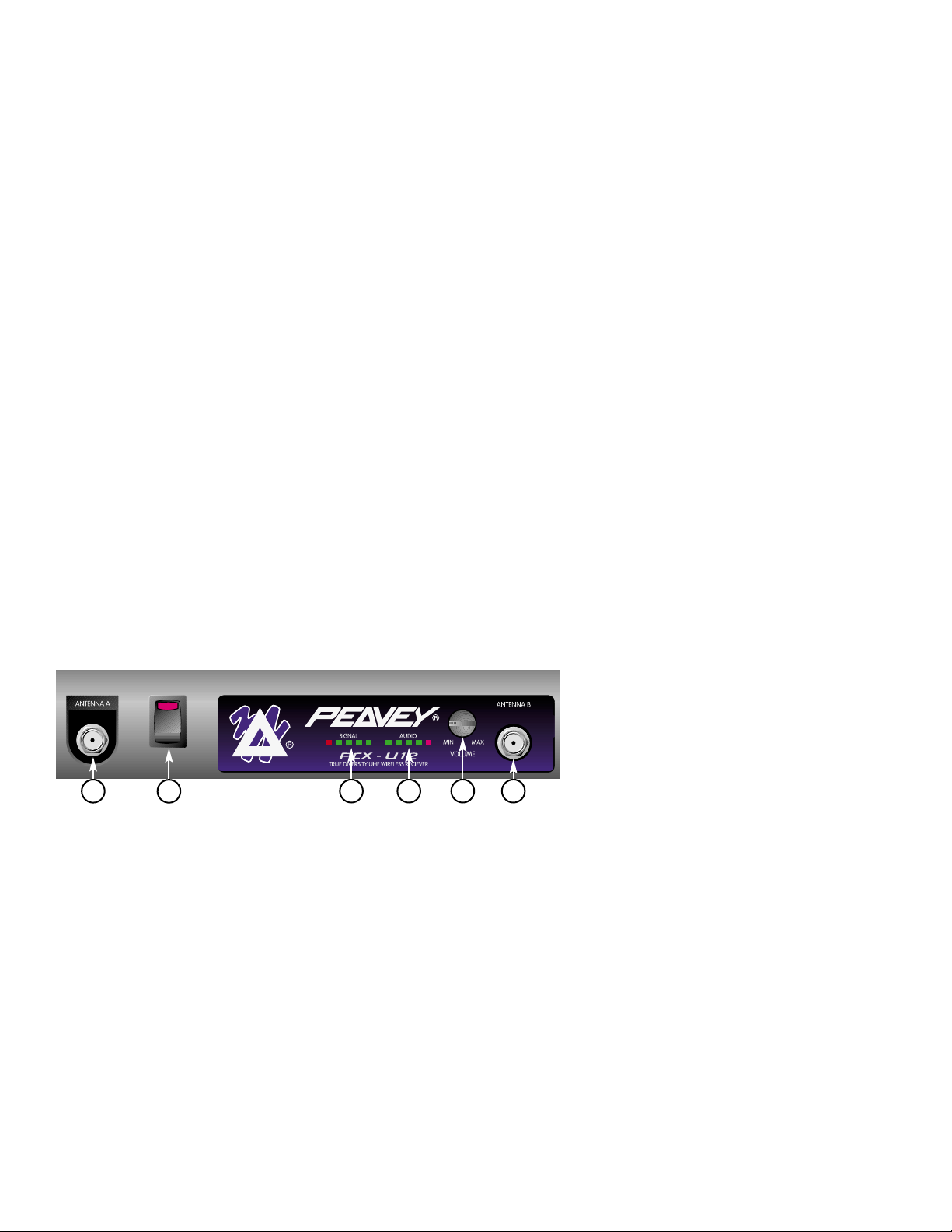
A. Front Panel
Figure 1
1
2
3 4 65
3
1. Antenna Input Connector A
2. Power Switch and Indicator:
When the switch is turned on the red indicator
illuminates to denote normal power status.
3. RF Signal Level Indicator:
Indicates the RF signal strength received from the
microphone. As soon as the signal is emitted from
the microphone the LED indicator illuminates.
4. Audio Signal Level Indicator:
Indicates the audio signal level. As soon as the
microphone signal is modulated, the LED indicator
illuminates.
5. Volume Control:
Adjusts the AF output level of the receiver.
6. Antenna Input Connector B
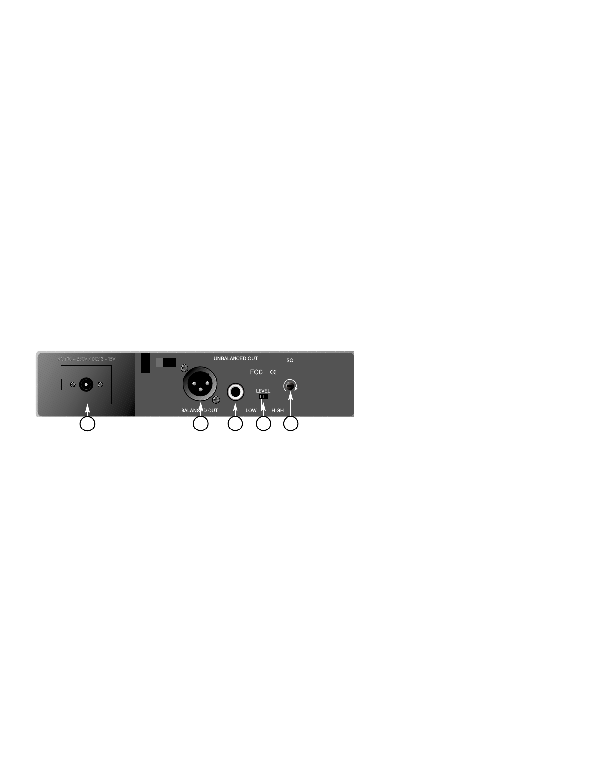
B. Rear Panel
7
8 9 10 11
Figure 2
4
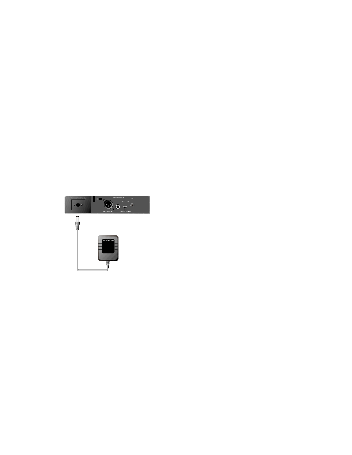
7. DC 12V Input Jack:
Connect the 12V DC plug from the AC/DC adapter.
8. Balanced Audio Output Jack:
XLR type connector
9. Unbalanced Audio Output Jack:
1/4" Phone Jack
10. Unbalanced Level Switch:
“LOW selection is for “Microphone-Level” output.
“HIGH” selection is for “Line-Out” level output.
11. Squelch Adjustment:
Adjust the squelch level to eliminate the RF noise
interference at the receiver.
2. INSTALLATION OF THE RECEIVER
1. Install one of the antennas at the antenna input
connector A. Then install the other antenna at
the antenna input connector B.
2. AC/DC Power Connection:
Figure 3
Connect the AC/DC adapter cable to the DC 12V
input jack. Then plug the adapter unit into an
appropriate AC outlet as shown in Figure 3. Caution:
Make sure the correct voltage is present at the AC
outlet as indicated on the AC/DC adapter.
5

3. Audio Output Connection:
a. Unbalanced Level Switch Setting Position:
Make sure to match the unbalanced output
setting to the device input setting. The
incorrect setting could result in low sensitivity
level or over load distortion. Ex. (If you are
going into the “Line” input on a mixer or
amplifier then the switch should be set to the
high position. If you are going into the “Mic”
input of an amplifier or mixer then the switch
should be set to the low position.)
b. Unbalanced Output:
Connect the 1/4" phone plug of the audio cable
into the unbalanced output connector on the
back of the receiver. Connect the other end of
the cable to the proper input of the desired
device. Make sure the unbalanced level switch
is in the proper position before applying power.
c. Balanced Output:
Connect the male XLR connector into the
balanced output connector on the back of the
receiver. Connect the other end of the cable
into the “Mic/Balanced” input of the desired
device. The characteristics of the 3-pin XLR
connector are shown below in Figure 4.
Figure 4
GND PIN 1
PIN 3
PIN 2
6
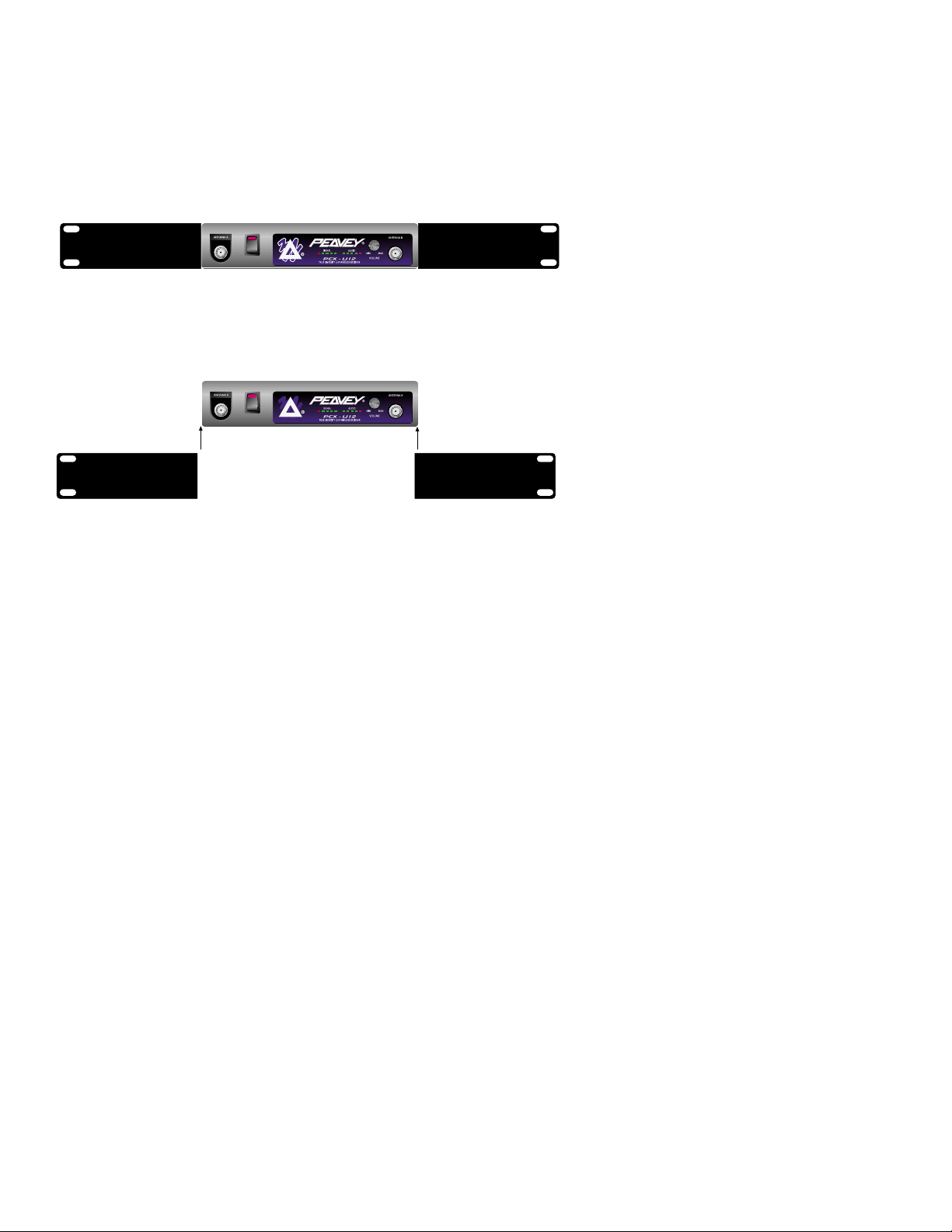
3. TWO 19/2-INCH UNITS RECEIVER INSTALLATION
A. Setup for single half-rack receiver
1. Push the rack mount brackets (RM-11)
upwards until it is firmly attached to the
receiver. (Figure 5)
Figure 5
B. Setup for dual half-rack receivers
1. Remove the screws at the top and
bottom of the receiver where they will
be joined together. Remove one steel
plate from each receiver. Push the
receivers next to each other. Refer to
Figure 6.
2. Insert the steel plate in between the two
receivers (top and bottom). Align and
fasten the screws tightly as shown in
Figure 6.
3. Align and fasten the rack mount
7

brackets (RM-12) on the outer sides of
both receivers as shown in Figure 6.
Figure 6
4. After completion, it can be rackmounted
into an EIA standard rack case. Shown
in Figure 7.
5. Make sure that the system performs
correctly by placing the system away
from noise sources. Place the receiver
at least one meter above the ground
and one meter away from noise
sources. Place the microphone at least
one meter away from the receiving
antenna, as shown in Figure 8.
Figure 7 Figure 8
8
 Loading...