

Page 1
DATA SHEET
Paperless Recorder
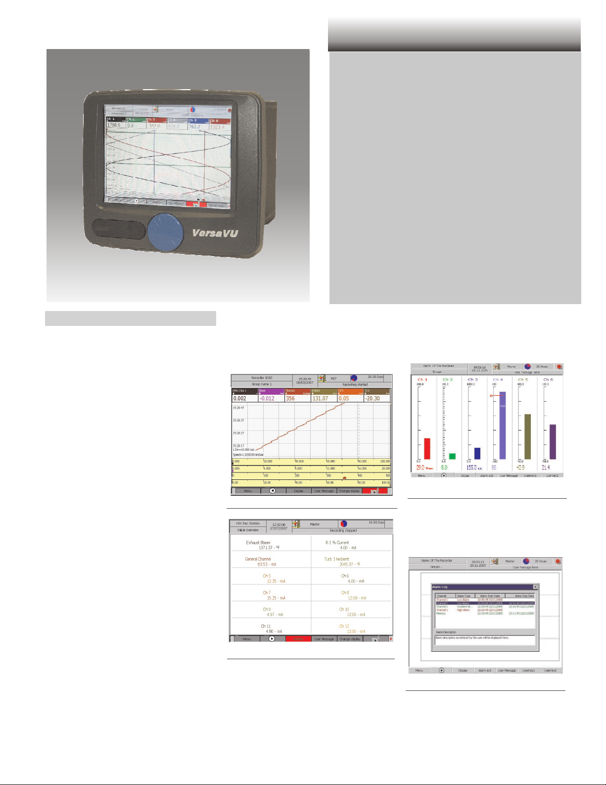
VersaVU
6.4" TFT Color Display Full VGA Resolution
Web based visualisation and configuration
Sampling Rate 250 ms
4, 8, or 12 universal 16-bit inputs
12 Relay Outputs
Up to 8 Display Strategies
USB Stick Memory Downloads
GENERAL
The VersaVU Paperless Recorder is a
freely configurable microprocessor-based
device for measurement, storage, visualization, monitoring, and documentation.
Available with 4, 8, or 12 universal inputs
VersaVU is expandable to an additional 12
inputs via Modbus communications.
Measured data is buffered in internal flash
memory and can be exported to a USB
stick via the front USB port. Data can also
be viewed via a standard web-browser for
quick evaluation and analysis of historical
data trends.
VersaVU has been designed for industrial
use incorporating the latest means for
communications. Complete configuration
can be accomplished using the standard
Ethernet interface and on-board webserver
which also permits easy to access data
monitoring. E-mail messaging and FTP
functions add the finishing touches for
complete user convenience . . all as standard features!
Measurement values can be displayed
either as trend curves in horizontal or vertical direction or bargraphs; a numeric display is also possible.
Trend display
RS 485 for Modbus master or Modbus slave
Ethernet interface for configuration
Mathematical functions in realtime
IP 65/NEMA 4x Front Panel Protection
VersaVU allows up to 8 visualization groups
with up to 12 input channels per group.
Bargraph display
Different display views can be activated
within each visualization group.
A Modbus serial interface is also standard
allowing the unit to function in slave or
master operation.
All of our product features are brought
together on our 6.4" TFT color display. We
incorporated full VGA resolution (640 x 480
pixels) with wide viewing angles making
full use of the screen size. This type of
resolution makes it easy to use complex
display strategies without sacrifice to visi
bility.
Digital display
VersaVU features a group manager allowing
the user to assign input signals to visualiza
tion groups.
Input signals can be assigned to multiple
groups improving transparency. Different
-
parameters can be used for every input
within a specified group.
-
Event list
A historical display of the data stored in
memory can be viewed via the Horizontal
Display.
Page 2

TECHNICAL DATA
ANALOG INPUTS
General
Programmable sensor type and measure
ment range.
Within a measurement range, span start
and end can be configured freely.
Scanning cycle
All inputs: Scan Rate: 250 ms
Resolution: 16 bits
Thermocouples
Input Type Measurement range
L -0.1 … 761.4 °C
J -200.1…1200.3 °C
K -240.1…1372.9 °C
N 0 … 1399.6 °C
S 0 … 1759 °C
R 0 … 1759 °C
T -240 … 400.5 °C
E -240 … 1000 °C
B 100… 1824 °C
Resistance thermometers
Type Measurement range
Pt 100 -199.9 … 800.3 °C
Ni 120 -80 … 260 °C
For all thermocouples and resistance thermometers, the smallest display span is 0.1
°C.
Direct voltage DC
Voltages can be measured and displayed in
the following ranges:
Input Type
DC Linear 0-50 mV 0 … 50 mV
DC Linear10-50 mV 10 … 50 mV
DC Linear 0-5 V 0 … 5 V
DC Linear 1-5 V 1… 5 V
DC Linear 0-10 V 0… 10 V
DC Linear 2-10 V 2 … 10 V
Direct current
Input Type
Current0-20mA 0… 20mA
Current4-20mA 4… 20mA
Measurement
range min
Measurement
range min
Measurement
range max
Measurement
range max
-
Accuracy and display
The errors specified in the table are
referred to the following conditions:
Humidity: 55% ± 10%
Temperature: 23 °C ± 2°C
Supply voltage: 100 to 240 V at 50/60 Hz ±
1%
VersaVU requires a 30 minute warm-up
period.
Standard performance
- Measuring accuracy (in %)
DC: +/- 0.1% of Span +/- 1 LSD
RTD: +/- 0.1% of Span +/- 0.3 deg C
TC: +/- 0.1% of Span, + 1 deg C
Cold Junction Compensation Error:
+0.3 deg C for 0.1 deg C resolution ranges
or 1 deg C for 1 degree resolution ranges
Recording accuracy (in resolution of the
digital display)
Fastest recording & displaying rates are 1
second. (1 data point per sec in file&1pix
per sec on display).
GENERAL INFORMATION
Maximum Input Voltage: DC voltage
input (±2 V or less)/thermocouple input
(burnout disable), ±10 Vdc
Maximum voltage for higher input
ranges (5V and 10V): 50Vdc
Input resistance: DC voltage(mV,V), thermocouple input;
approximately 1 MÙ
Input resistance for mA input: 6.2 ohm
Source Resistance:> 1kÙ for current inputs
Allowable Signal Source Resistance:
Thermocouple Input (Burnout Disable)/DC
voltage input (±2 V or less):
1kÙ or less
DC Voltage Input (±5 to ±50 V):
100 Ù or less
Resistance Thermometer:
Per wire 10 Ù or less (same resistance
for 3 wires)
Input bias current: 10 nA or less
Interference across channels: 120 dB (for
500 Ù input external resistance and 60 V
input to other channel)
Noise (50/60Hz power supply) for VDC,
RTD and TC input
Maximum common mode noise voltage:
250 VAC rms (50/60 Hz)
Normal mode rejection ratio (NMRR):
40 dB (50/60 Hz ±0.1%)
Common mode rejection ratio (CMRR): 120
dB (50/60 Hz ±0.1%, 500 Ù unbalanced,
across minus terminal and ground)
Maximum noise voltage across channels:
250 VAC RMS (50/60 Hz)
Interference across channels: 120 dB (for
500 Ù input external resistance and 60 V
input to other channel)
DISPLAY / OPERATION
TFT Color Display
Screen Size: 6.4" measured diagonally
Resolution: VGA, 640 x 480 pixels
Operating Languages: English, German,
French, Italian, and Spanish
VersaVU is operated via a rotary push-button
knob on the front panel or through the integrated Webserver.
Configuration is done via the front knob, the
integrated Webserver, or USB memory stick.
(USB stick not in delivery).
DATA STORAGE
Internal data storage: 150MB Flash
Optional external storage:
Data storage will be initiated automatically in
a range of 1sec. to 60 min.
Historical data can be downloaded via
USB-Stick, Webserver or FTP Transfer.
POWER SUPPLY
Supply voltage: 100..240 VAC
Frequency: 50/60 Hz
(automatic detection)
ENVIRONMENTAL CONDITIONS
Normal operating conditions:
Operating
Temperature
Operating humidity
range
Warm-up time: 30 minutes
Industrial 0 to 55 deg C or 32
to 131 deg F
Relative Humidity 30 to 90%
non-condensing; no specific
pressure range
TRANSPORT AND STORAGE
CONDITIONS
Temperature: -10...55°C
Humidity: 5...95%, no condensation
Vibration: 10-55 Hz, 10m/ s² for 2 hours
2 VersaVU
Page 3

CONFORMITY / SAFETY
Safety and EMC standards
UL 508 / CE
•
EN 61010-1 (OV II, PD II &
•
Protection Class II)
EMC requirements
EN 61000-6-2 (EN 50082) and
•
EN 61000-6-4 (EN 50081)
EN 61326-1
•
Test conditions
Dielectric Strength: 3000 VAC, 50/60
•
Hz for 1 minute - per UL test
Insulating resistance: 20 MÙ or
•
greater across output and main unit
ground (500 VDC)
Withstand voltage: 500 VAC across
•
output and main unit ground (50/60
Hz;I=10mA), for one minute
Signal insulation:
Between communication terminal :
•
500 V rms withstand voltage and
ground (50/60 Hz, for one minute)
Across input terminals: 500 VAC
•
(50/60 Hz;I=10mA), for one minute
ALARM OUTPUTS
12 alarm outputs are available (optional)
Type: SPDT (NO) relay
Rating: 3A resistive@240VAC (50/60Hz)
RETRANSMISSION OUTPUTS
•
Retransmission of up to 6 internal
channels to analog outputs.
•
Analog outputs can be configured to
be either internally or externally
powered.
SERIAL INTERFACES
VersaVU comes standard with RS-485 and
Ethernet communications.
With Modbus operation, the unit can be
configured as Modbus master (external
channels) or as Modbus slave .
Ethernet: Modbus TCP
•
RS 485: Modbus RTU
•
When configured as a Modbus master,
VersaVU can be expanded to an additional
12 external channels over communications.
ETHERNET INTERFACE
The Ethernet interface offers the following
protocols and functions:
Timeserver
–
E-mail function for sending alarm mes-
–
sages and data.
Web server function for displaying a
–
standard operating interface on a
browser (IE6 or higher).
FTP client function for automatic data
–
transfer from the recorder to an FTP
server.
– Configuration of the unit with the inte-
grated webserver
–
Download of data via browswer
MATHEMATICS FUNCTION (OPTION)
The ‘Mathematics’ function enables up to
twelve additional channels to be defined.
The functions include general arithmetic
calculations, logic operations, statistical
functions, reporting functions, and triggering of automatic sequences.
DIGITAL INPUTS (OPTION)
Digital Input
Switching thresholds
Maximum low level voltage Ulmax < 5V
Minimum high level voltage Uhmin >15V
Nominal differential Input
voltage
Permissible range of inputs -3 V to + 36 V DC or
Nominal Input current for Uin 5 mA
Permissible cable length to the
sensor
Isolation between channels
24VDC
0to25VAC
100 m
500V
BUFFER OVERFLOW (OPTION)
The ‘buffer overflow’ signal is available as a
relay output rated at 250 VAC, 3 A. The signal is triggered at a specified time during
recording. It is always available as standard
alarm (alarm list)
GENERAL
PROTECTION MODE
To EN 60529
Front IP 65, rear IP 20
NEMA 4X
HOUSING
Sheet steel housing for mounting in a panel
cutout.
Panel fixing elements to DIN.
Dimensions
5.47”
5.47”
Analog Output
Output Range 0-20 or 4-20mA
Resolution 12 bits
Accuracy at 25 °C +/- 0.1% of full scale
Temperature Drift +/- 0.01% / °C
Output current Ripple 1%
Output Load
(working resistance)
Isolation between
Channels
Rise time from 10% to
90%
(Configurable through
HMI)
0 – 650 Ohm
500 V (NA if used with
external power supply)
100mS
Depending on the model ordered, VersaVU
can be fitted with 8 remote control inputs.
These inputs can be used to trigger the following functions:
–
Start / Stop of recording
–
Timer reset
–
Counter function
–
Operating hours counter
–
Display / recording of the digtal input
–
Screen dump
–
Operator message
VersaVU 3
Panel cutout
5.375”H X 5.44”W X 7.0” D (Enclosure)
6.5”H X 7.375 X1.06” D (Bezel)
Weight:
5.56 lbs without packaging and
7 lbs with packaging
Page 4

ORDER NO
Technical Support +1 800.866.6659
www.partlow.com
Printed in Germany - Edition 08/2008i - Subject to change without notice - 9498 737 59513
 Loading...