

Page 1
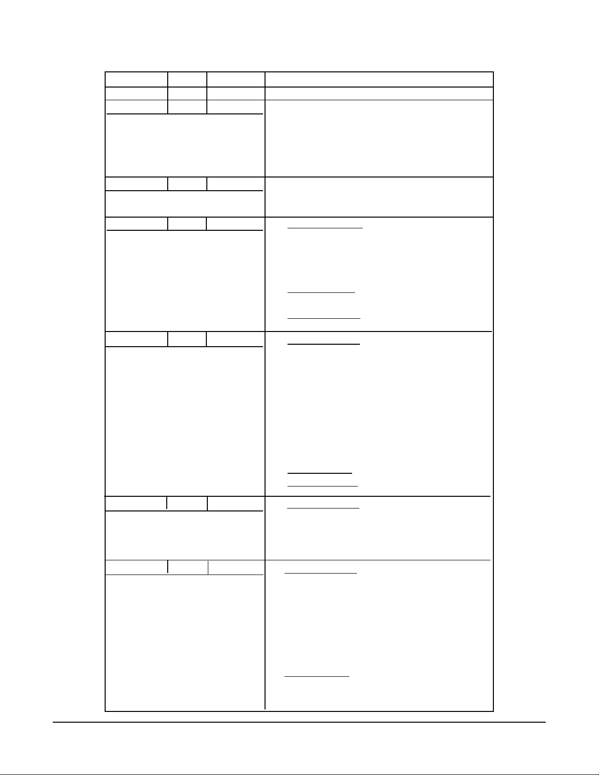
VersaChart Manual Revision Log
Revision Date Description
Edition 1 6/16/95 Released
Edition 1 RevA 7/14/95 Revised Pages: 4, 5, 1-1 thru 1-5, 2-8,
4-3, 4-5, 4-6, 4-9 thru 4-11, 4-17, 4-37,
4-39, 4-40, 4-42, 4-48, 4-50, 4-57,
4-100, 4-101, 7-1 thru 7-3, 10-1, 11-1,
C-2, C-3, C-5 thru C-7, C-10, C-11, C-13;
added D-1 thru D-4 and E-1 thru E-2.
Edition 1 Rev B 8/10/95 Revised Pages: 2-9 thru 2-13, 3-16, 4-13,
4-29, 11-2 thru 11-7, B-1 thru B-2, C-4,
C-10 and E1 thru E3.
Edition 1 Rev C 11/6/95 Revised Pages: 5, 1-3, 1-5, 2-6, 2-15,
3-5, 3-6, 3-35, 4-8, 4-17, 4-26, 4-45,
4-79 thru 4-101, 6-9 thru 6-14, 8-1,
10-1 thru 10-2, 11-4, 11-6, A-1, A-4,
E1 thru E3;
Added Pages: 10-3 thru 10-5, 11-7 thru
11-8, A-6 thru A-7, D-7;
Deleted Pages: 4-102.
Edition 1 Rev D 4/15/96 Revised Pages: 1, 3, 5, 1-3 thru 1-6, 2-1,
2-3, 2-4, 2-6, 2-8, 2-15, 2-16, 3-3 thru 3-8,
3-10, 3-11, 3-19 thru 3-21, 3-24, 3-28,
3-29, 3-36 thru 3-39, 4-1 thru 4-3,
4-6 thru 4-13, 4-15, 4-17, 4-18, 4-23,
4-24, 4-26, 4-30, 4-31, 3-35, 4-58, 4-59,
4-62, 4-63, 4-65 thru 4-67, 4-71, 4-73,
4-74, 4-77 thru 4-99, 5-2, 6-1, 6-6, 6-12,
6-13, 8-4, 9-3 thru 9-8, 10-4, 11-5 thru
11-8, A-2, B-2, E-2.
Added Pages: 8-5, 9-7, 9-8, A-8.
Deleted Pages: 4-100, 4-101.
Edition 1 Rev E 9/18/96
Edition 2 Rev F 4/1/97 Revised Pages: 1-1, 1-3, 1-4, 1-5, 2-16, 3-
Prefix & Table of Contents
Revised Pages: 1, 2-2, 4-23 thru 4-24,
4-58 thru 4-59, 4-63, 4-65, 4-67, 4-73 thru
4-74, 4-80, 4-87, 4-91, 4-95 thru 4-96,
11-1 thru 11-4, C5, C14, D-3
13, 3-16, 3-17, 3-23, 3-29, 3-33, 3-44, 4-2,
4-17, 4-20, 4-21, 4-22, 4-23, 4-24, 4-34, 436, 4-38, 4-39, 4-41, 4-42, 4-45, 4-54, 458, 4-59, 4-63, 4-65, 4-66, 4-67, 4-68, 469, 4-73, 4-74, 4-75, 4-77, 4-78, 4-80, 487, 4-91, 4-93, 4-94, 5-1, 6-6, 6-12, 6-13,
8-2, 8-3, 8-4, 8-5, 9-2, 9-6,
Added Pages: 3-24, 3-25, 3-36, 3-37, 343, SEC 13
1
Edition 3
Rev G
Page 2

Revision Date Description
Edition 3 Rev G 7/1/98 Revised Pages: 9-2 thru 9-22
Added Pages: SEC 14
Edition 3
Rev G
2
Prefix & Table of Contents
Page 3

VersaChart Manual Prefix
MANUAL ORGANIZA TION
This manual is organized in twelve major sections:
Section 1 Introduction and General Information
Section 2 Installation and Wiring
Section 3 The Basics of Recorder Operation
Section 4 Configuration
Section 5 Display Programming
Section 6 Chart Prompts
Section 7 Alarm Settings
Section 8 Action Time Settings
Section 9 Enables & Passwords
Section 10 Test
Section 11 Calibration
Section 12 Appendix
Section 13 Controllers
Section 14 Profilers
All users should be familiar with the first three sections of this manual before beginning to operate the recorder.
Operators are then advised to cover the Display Programming, Chart Prompts and Alarm Setting sections.
Configurators should be familiar with all information, particually the details in the Configuration Programming
section.
P ARTLOW TECHNICAL AND APPLICATION SUPPORT
Please have your recorder model number AND serial number available before calling for technical and application
support. Support is available from:
The Partlow Corporation
2 Campion Road
New Hartford, NY 13413
1-800-866-6659 or 1-315-797-2222
Fax: 1-315-797-0403 or 1-315-793-1864
Prefix & Table of Contents
3
Edition 3
Rev G
Page 4

Table of Contents
P AGE
SECTION 1 - INTRODUCTION AND GENERAL INFORMATION 1-1
1.1 Unpacking 1-1
1.2 Installation of Pen Cartridge Assembly 1-2
1.3 Order Matrix/Model Number 1-3
1.4 Specifications 1-4
1.5 Warranty Statement 1-7
SECTION 2 - INSTALLTION AND WIRING 2-1
2.1 Mounting 2-1
2.2 Preparation for Wiring 2-3
2.3 Wiring Connections - Inputs 2-6
2.3.1 Shipped Configuration/Jumper Positioning 2-7
2.3.2 Sensor Break 2-7
2.3.3 AC Power Connections 2-8
2.3.4 Thermocouple Connections 2-9
2.3.5 RTD Connections 2-10
2.3.6 Voltage Connections 2-11
2.3.7 Current Connections 2-12
2.3.8 Switch Input Connections 2-13
2.4 Wiring Connections - Outputs 2-14
2.4.1 SPDT Relay 2-14
2.4.2 Solid State Relay Driver (SSRD) 2-14
2.4.3 Current Output 2-15
2.4.4 24 VDC Transmitter Power Supply 2-15
2.4.5 Communications 2-16
SECTION 3 - THE BASICS OF RECORDER OPERATION 3-1
3.1 Power-Up 3-1
3.2 Instrument Modes 3-1
3.2.1 Normal Display 3-1
3.2.2 Display Prompts 3-1
3.2.3 Chart Prompts 3-1
3.2.4 System Prompts 3-1
3.3 Keypad Functions 3-2
3.3.1 DISPLAY key 3-2
3.3.2 CHART key 3-2
3.3.3 SCROLL key 3-2
3.3.4 ARROW keys 3-2
3.3.5 RESET key 3-2
3.3.6 ESCAPE key, MODIFY key, ENTER key 3-2
3.3.7 Special keys 3-2
3.4 Changing Parameter Settings - Modify 3-3
3.4.1 Changing Values 3-3
3.4.2 Changing Text 3-3
3.4.3 Changing Choices 3-3
3.4.4 Copy/Initialize 3-4
3.4.5 Passwords 3-4
3.4.6 Enables 3-4
3.5 The Display 3-4
3.6 General 3-4
3.7 Display Details 3-5
3.8 Chart Details 3-7
Edition 3
Rev G
4
Prefix & Table of Contents
Page 5

PAGE
3.8.1 Chart Printing Interruptions 3-8
3.8.2 New Chart Printing Requirements 3-9
3.8.3 Example Chart 3-9
3.8.4 Sequence of Events 3-12
3.9 Getting Started 3-13
3.10 Quick Start Procedure 3-14
SECTION 4 - CONFIGURATION 4-1
4.1 Entering Configuration 4-1
4.1.1 Inputs 4-1
4.1.2 Constants 4-14
4.1.3 Custom Curves 4-15
4.1.4 Derived Variables 4-18
4.1.5 Process Variables 4-32
4.1.6 Recorders 4-43
4.1.7 Totalizers 4-52
4.1.8 Timers 4-61
4.1.9 LEDs 4-64
4.1.10 Relays 4-66
4.1.11 Current Outputs 4-69
4.1.12 Instrument Settings 4-72
4.1.13 Derived Actuators 4-78
4.1.14 Operator Inputs 4-81
4.1.15 Operator Messages 4-85
4.1.16 Chart Messages 4-89
4.1.17 Simulated Variables 4-95
SECTION 5 - DISPLAY PROGRAMMING 5-1
SECTION 6 - CHART PROMPTS 6-1
6.1 Change Chart 6-1
6.2 Chart Configuration 6-2
SECTION 7 - ALARM SETTINGS 7-1
SECTION 8 - ACTION TIME SETTINGS 8-1
SECTION 9 - ENABLES & PASSWORDS 9-1
SECTION 10 - TEST 10-1
SECTION 11 - CALIBRATION 11-1
SECTION 12 - APPENDIX
A - Board Layouts A-1
B - Ranges B-1
C - Reference Section C-1
D - Examples D-1
E - Accuracy Tables E-1
Prefix & Table of Contents
5
Edition 3
Rev G
Page 6

PAGE
SECTION 13 -CONTROLLERS 13-1
13.1 Entering Controllers 13-3
13.2 Control Setpoints 13-18
13.3 Control State Access 13-22
13.4 Tuning Parameters 13-31
SECTION 14 -PROFILERS 14-1
14.1 Profile Entry 14-1
14.2 Profile Settings 14-4
14.3 Profile Control 14-7
Figures and T ables
Figure 1-1 Pen Cartridge Installation 1-2
Figure 2-1A Mounting Dimensions 2-1
Figure 2-1B Dimensional Drawing 2-2
Figure 2-2 Noise Suppression 2-4
Figure 2-3 Noise Suppression 2-4
Figure 2-4 Board and Terminal Locations 2-6
Figure 2-5 Shipped Jumper Positions 2-7
Figure 2-6A AC Power Connections, 115/230 2-8
Figure 2-6B AC Power Connection, Universal 2-8
Figure 2-7 TC Connections 2-9
Figure 2-8 RTD Connections 2-10
Figure 2-9 Voltage Connections 2-11
Figure 2-10 Current Connections 2-12
Figure 2-11 Switch Input Connections 2-13
Figure 2-12 SPDT Relay Output 2-14
Figure 2-13 SSR Driver Output 2-14
Figure 2-14 Current Output 2-15
Figure 2-15 Transmitter Power Supply 2-15
Figure 2-16 RS-485 Communications 2-16
Figure 2-17 RS-232 Communications 2-16
Figure 3-1 Keypad 3-2
Figure 3-2 Example of Chart 3-12
Figure 11-1 Jumper Positions for Calibration 11-3
Figure A-1 Power Supply Board A-1
Figure A-2 Mother Board A-2
Figure A-3 Relay/SSR Board A-3
Figure A-4 Input Board A-4
Figure A-5 Motor Driver Board A-5
Figure A-6 Current Output Board A-6
Figure A-7 Transmitter Power Supply A-7
Figure A-8 Communication Board A-8
Table 2-1 Board ID Jumpers 2-7
Table 3-1 Configure Chart Parameters 3-10
Table 3-2 Recorder Parameters 3-11
Table 10-1 Available Tests 10-1
Table 11-1 Calibration Routines 11-1
Table 11-2 Range Select 11-2
Table 11-3 Input Board Jumper Positions 11-3
Edition 3
Rev G
6
Prefix & Table of Contents
Page 7

Section 1 - Introduction and General Information
This instrument is a microprocessor based circular chart recorder capable of measuring, displaying, and recording
from a variety of inputs. Applications include temperature, level, pressure, flow, and others. The instrument can
be specified as either a one, two, three, or four pen model.
The standard process sensor inputs (up to 8 total inputs) are user configurable to directly connect to and convert
thermocouple, RTD, millivolt, volt, milliamp or contact closure inputs. Thermocouple and RTD linearization, as
well as thermocouple cold junction compensation, are performed automatically. Up to four individually isolated 24
VDC regulated transmitter power supplies are available for transmitter inputs, each providing up to 25 mADC.
Using the optional math capability, mass flow, BTUs, relative humidity, and other derived variables can be calculated, as well as simple math functions performed and custom curve conversions. Optional totalization is available for input values or derived variables. Any recorder value can be treated as a process value, to provide
alarming and special display capability.
Up to 4 variables can be recorded as analog trend lines on chart sizes of 10, 11, or 12 inches in diameter. The
trend lines can be the result of instantaneous values, connecting the values, drag pen, average values, or connecting the average values. The trend lines can be scaled and positioned on the chart in zones. Trend scales,
units, and a trend tag can be printed in the same color as time lines.
Dates, times, batch numbers, operator IDs, process values, scales and alarm messages can all be printed on the
chart in color.
Definitions for a large number of "Terms and Concepts" described in this manual are included in Appendix C.
1.1 UNP ACKING
Remove the instrument and pen cartridge assembly from the shipping container and inspect for any damage due
to shipment. If any damage is noticed due to transit, report and file a claim with the carrier. Write the model
number and serial number in spaces provided on Page 1-3 of this manual for future reference. The model
number and serial number are found on the label on the case, viewed when platen is open.
!
CAUTION: READ THIS MANUAL
THE INTERNATIONAL HAZARD SYMBOL IS FOUND ADJACENT TO THE
LOWER PLA TEN HOLD DOWN SCREW. IT IS IMPORTANT TO READ
THIS MANUAL BEFORE INSTALLING OR COMMISSIONING THE UNIT.
Section 1
1-1
Edition 3
Rev G
Page 8
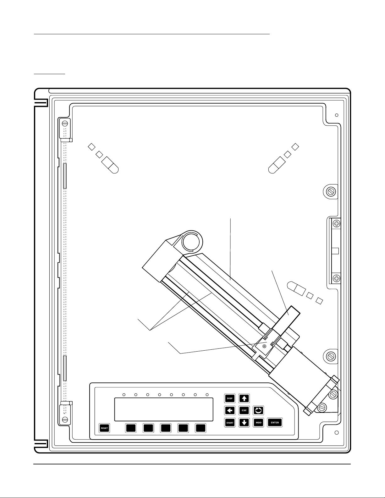
1.2 INSTALLATION OF PEN CARTRIDGE ASSEMBLY
Remove the pen cartridge assembly from its shipping container. With mounting tab on the bottom, slide the pen
cartridge assembly (item 2 on Figure 1-1) into the print actuator (item 1 on Figure 1-1).
FIGURE 1-1
PLASTIC CHART SHIELD
(DO NOT REMOVE)
PRINT ACTUATOR
TRAVERSE CABLE
PRINT ACTUATOR (1)
1 2 3 4 5 6 7 8
INSTALL PEN
CARTRIDGE (2)
Edition 3
Rev G
1-2
Section 1
Page 9
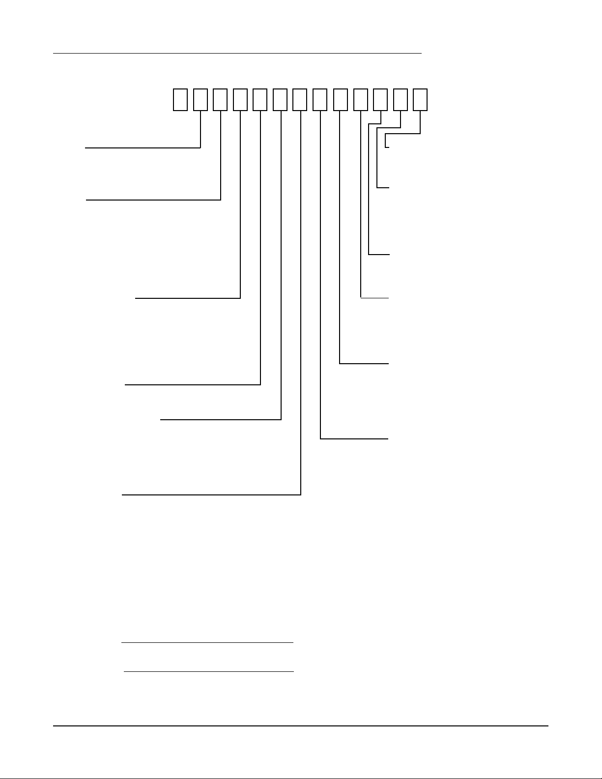
1.3 ORDER MATRIX/MODEL NUMBER
9
TYPE
1 Recorder Only
2 Controller
3 Profiler
PENS
1 One Trend Pen, One Color*
2 Two Trend Pens, Two Colors*
3 Three Trend Pens, Three Colors*
4 Four Trend Pens, Four Colors
5 One Trend Pen, Four Colors
6 Two Trend Pens, Four Colors
7 Three Trend Pens, Four Colors
UNIVERSAL INPUTS
1 One Input
2 Two Inputs
3 Three Inputs
4 Four Inputs
6 Six Inputs
8 Eight Inputs
DIGITAL INPUTS
0 None
RELAY OUTPUTS (SPDT)**
0 None
2 Two Relays
4 Four Relays
6 Six Relays
8 Eight Relays
SSR OUTPUTS**
0 None
2 Two SSRDs
4 Four SSRDs
6 Six SSRDs
8 Eight SSRDs
CASE TYPE & MOUNTING
1 NEMA3 Panel Mount
2 NEMA4 Panel Mount
ENCLOSURE OPTIONS
1 Glass Window
2 Glass Window & Door Lock
3 Plastic Window
4 Plastic Window & Door Lock
MEMORY CARD/COMMS
0 None
1 RS-485/232 Comms
MA TH/TOT ALIZER
0 None
1 Math
2 Totalizer
3 Math & Totalizer
TRANSMITTER POWER SUPPL Y
0 None
1 One Trans. Power Supply
2 Two T rans. Power Supply
3 Three Trans. Power Supply
4 Four Trans. Power Supply
4-20mA OUTPUTS
0 None
1 One 4-20 mA Output Non-Isolated
2 Two 4-20 mA Outputs Non-Isolated
3 One 4-20 mA Output Isolated
4 Two 4-20 mA Outputs Isolated
5 Three 4-20 mA Outputs Isolated
6 Four 4-20 mA Outputs Isolated
* Pens/colors are added to the instrument in the following order: red, then green, then blue,
and then black.
** Total quantity of SPDT Relays and SSR Drivers must be less than or equal to eight.
Model Number
Serial Number
Section 1
1-3
Edition 3
Rev G
Page 10

1.4 SPECIFICATIONS
DESCRIPTION
The instrument is the first circular chart recorder with the ability to record trend data and print alphanumeric annotation in four
colors. It uses unique "rings only" charts and has the ability to zone and scale trend data. These capabilities not only provide
the best trend data readability, but also instant association with the corresponding scales. Whether it's a basic application of
recording inputs, to a demanding application requiring derived variables, logic functions, totalization, or other capabilities, the
instrument can be supplied with the necessary level of sophistication, while maintaining an uncomplicated operator interface.
MODELS
The instrument is available in versions for trend recording of one to four values. The number of colors can equal the number of
trended values, or all four colors can be provided. The latter option provides the greatest color flexibility and makes it easier to
add trend capability to the instrument in the field. The instrument can have up to eight inputs, and inputs are not directly
associated with trend pens. The instrument can trend any combination of inputs, averages, derived variables, logic states, even
totals. A full compliment of options provides the flexibility to handle virtually any type of application.
FEATURES
• Color chart annotation
• 1, 2, 3 and 4 trend pen versions
• All versions with optional four color capability
• 10", 11", or 12" charts
• Linear scales and radial time lines
• Trend zoning and dual zone capability
• Up to 8 universal inputs
• 40 character, vacuum fluorescent display
• Simultaneous display of up to 4 process values
• Building block approach for flexibility
• Math and equation package with custom curves
• Logic equations for actuators
• 9 digit totalizes
• Chart messages
• Operator inputs
• Operator messages
• Real time clock
• Time and date printed on charts
CONFIGURATION
A multilevel prompting scheme provides rapid access to all configuration data. By model number and selective enabling, the
software displays only those configuration sections needed. The 40 character, vacuum fluorescent display provides true English
language prompts. The 15 key keypad makes moving through the prompts and modifying the parameters intuitive. Multiple
choice selections and use of "quick select keys" simplifies the programming of many parameters. Copy functions make
configuring similar sets of parameters even faster. Two methods of modifying character strings simplifies the entry of English
tags and units. The instrument even displays the proper jumper placement for the installer. The instrument can virtually be
configured without looking at the manual.
Edition 3
Rev G
1-4
Section 1
Page 11

OPERATOR INTERFACE
Beyond the configuration capability, the display, keypad, and prompting system provide superior real time data presentation.
The display of each instrument value is configurable and three display formats are available, providing a range from fully
detailed displays with 20 character tags, alarm indications, values, and units, to four process values displayed simultaneously.
Separate keys are used to access the display, chart, and configuration related areas. By selective enabling and password
protection, access to various operational areas of the instrument can be limited or controlled. Some keys can also be configured to provide special functions, such as resetting totalizers. The operator interface has been designed to make daily operation
as simple as possible. Changing charts, for example, requires only three keystrokes.
CONSTRUCTION
The instrument is housed in a structural foam moulded enclosure which can be panel or surface mounted. Mounting brackets
are included. Its design allows it to fit into the smallest panel cutout of competitive products, while it covers the largest cutout
of others. Glass and plastic windows are available, along with a cover lock. The standard enclosure carries a NEMA3 rating,
with an optional NEMA4X available.
OPTIONS
The instrument is available with a full compliment of options. Up to eight isolated universal inputs are available with each being
configurable to any of the available input types. Up to four isolated transmitter power supplies can be added. Up to four inputs
or derived variables can be assigned as "process variables", allowing up to four alarms for each. Alarms can be process high or
low, or rate rising or falling. The alarming capability is standard, but the hardware outputs are optional. Up to eight on/off
outputs are available, either relay or solid state relay driver outputs. Besides alarms, any of over eighty other digital values/
states can be used to actuate on/off outputs. Up to two non-isolated analog outputs or up to 4 isolated analog outputs are
available. Any of over twenty values can be used to drive analog outputs (i.e. inputs, derived variables, etc.) Other options
include PC based configuration software and a communications interface.
FIELD UPGRADES
All of items listed in the Options section are easily installed in the field. Typically it involves just adding boards, but possibly
PROMs may need to be changed as well. To add totalizers or the math package, only PROMS must be changed. If the four
color option was purchased, only PROMS need to be changed to expand trend capability, otherwise, a relative costly pen arm
assembly must be replaced as well.
Section 1
1-5
Edition 3
Rev G
Page 12

INPUTS
Input Types
Thermocouple Types J, K, T, R, S, E, B, N, G, D, C, Ni/Ni-Moly, and Platinel II.
RTD Platinum 100, 2 or 3 wire
.00385 coefficient DIN 43760/IEC 751
.00392 coefficient USA
.00392 coefficient SAMA
Nickel 100, 2 or 3 wire
Voltage DC 0 to 25mV, 0 to 100 mVDC, 0 to 1 VDC, 0 to 10 VDC
Current DC 0 to 20mA, 4 to 20mA
Internal 50 ohm shunt resistor
Contact Closure Open/closed switch sensing without external voltages or resistors
Impedance 25mV, 100mV, 1 Volt: > 10 meg ohms
10 Volt: > 50 K ohms
mA: 50 ohms
RTD Excitation Current 1 mA
INPUT PERFORMANCE
Measurement Error ± .025% of measurement span reference accuracy
Cold Junction Compensation Error ± 0.2°C @ 25 degrees C
Cold Junction Compensation Rejection 0.04°/degree C deviation from 25 degrees C
Linearization Error TCs: ± 0 .25°C typical, ± 0.5°C worst case with exceptions
RTDs: ± 0.1°C typical, ± 0.3°C worst case
Ambient Temperature Error ± 0 .01% of span per degree C deviation from 25 degrees C
Factory Calibration Error Refer to the Accuracy Table
Isolation 500 VDC/350 VAC
Common Mode Rejection 120 dB min.
Normal Mode Rejection 100 dB min. @ 60 Hz or greater
Scan Rate The input scan rate is programmable and dependant on the number of active
inputs present. The total scans per second for the instrument is 16 scans/
second, and the instrument can have up to 8 inputs configured.
Edition 3
Rev G
1-6
Section 1
Page 13
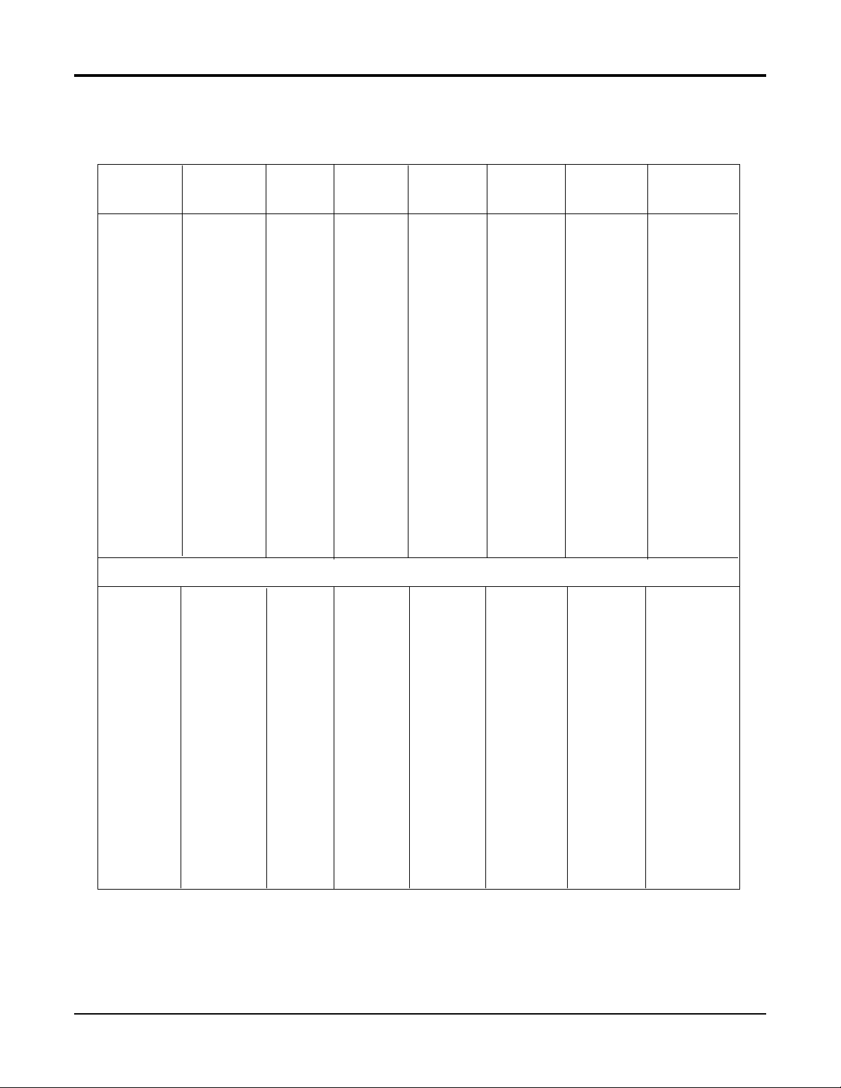
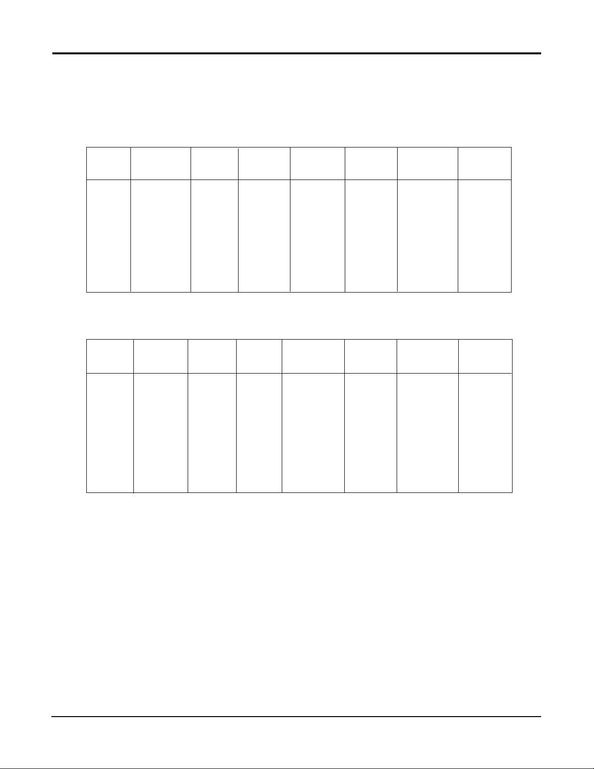
ACCURA CY T ABLES
TC
TYPE
J
WIDE
J
NARROW
K
WIDE
K
NARROW
E
WIDE
E
NARROW
N
WIDE
N
NARROW
See Note:
RANGE
°C
0/1200
-200/0
0/400
-200/0
0/1370
-250/0
0/500
-250/0
0/1000
-250/0
0/300
-250/0
0/1300
-250/0
0/600
-200/0
-250/-200
1
REF
ACC'Y
°C
0.43
0.63
0.11
0.16
0.62
1.05
0.15
0.26
0.33
0.66
0.09
0.17
0.68
1.44
0.18
0.31
0.93
2
LIN.
ACC'Y
°C
0.20
0.08
0.05
0.08
0.26
0.30
0.08
0.30
0.19
0.42
0.19
0.42
0.21
0.60
0.11
0.20
0.60
3
FACTORY
CAL
°C
0.32
0.56
0.33
0.56
0.40
0.78
0.39
0.78
0.28
0.62
0.29
0.62
0.42
0.93
0.44
0.81
2.15
4
REF+LIN
+CAL
°C
0.95
1.28
0.50
0.80
1.28
2.13
0.62
1.35
0.80
1.71
0.57
1.21
1.32
2.97
0.73
1.32
3.68
5
DEVIATION
ACC'Y
°C
0.12
0.02
0.04
0.02
0.14
0.03
0.05
0.03
0.10
0.03
0.03
0.03
0.13
0.03
0.06
0.02
0.01
6
RESOL
°C/bit
0.066
0.097
0.017
0.024
0.095
0.159
0.023
0.040
0.050
0.101
0.014
0.025
0.104
0.220
0.028
0.048
0.142
To achieve stated results, the following thermocouples must be used with the INPUT TYPE/RANGE set to TC NARROW
G
C
D
NNM
Platinel II
1800/2300
800/1800
500/800
300/500
0/300
1800/2300
1200/1800
300/1200
0/300
1800/2300
300/1800
0/300
450/1370
0/450
1000/1400
500/1000
0/500
1.59
1.23
1.38
1.79
3.65
2.14
1.62
1.33
1.54
1.88
1.32
1.75
0.44
0.56
0.72
0.59
0.62
0.54
0.43
0.25
0.25
0.58
0.54
0.43
0.28
0.12
0.38
0.40
0.26
0.33
0.13
0.28
0.20
0.10
0.79
0.64
0.70
0.87
1.61
1.01
0.80
0.68
0.77
0.90
0.68
0.85
0.33
0.37
0.44
0.38
0.40
2.92
2.30
2.33
2.91
5.84
3.68
2.85
2.29
2.43
3.26
2.40
2.86
1.10
1.06
1.44
1.17
1.12
0.05
0.10
0.03
0.02
0.03
0.05
0.06
0.09
0.03
0.05
0.15
0.03
0.09
0.05
0.04
0.05
0.05
0.243
0.188
0.210
0.274
0.557
0.326
0.247
0.202
0.235
0.287
0.201
0.267
0.067
0.085
0.110
0.089
0.095
Section 1
1-7
Edition 3
Rev G
Page 14
ACCURA CY T ABLES CONT .
To achieve stated results, the following thermocouples must be used with the INPUT TYPE/RANGE set to TC NARROW
TC
TYPE
T
R
S
B
RTD
TYPE
385
DIN
392
USA
See Note:
RANGE
°C
0/400
-200/0
-250/-220
800/1700
200/800
250/1750
200/1800
See Note:
RANGE
°C
-160/480
-200/-160
-100/450
1
REF
ACC'Y
°C
0.12
0.23
0.73
0.43
0.58
0.56
0.74
1
REF
ACC'Y
°C
0.16
0.14
0.16
2
LIN.
ACC'Y
°C
0.09
0.19
0.36
0.19
0.25
0.25
0.31
2
LIN.
ACC'Y
°C
0.03
0.20
0.03
3
FACTORY
CAL
°C
0.34
0.70
1.90
0.83
1.08
1.05
1.34
3
FACTORY
CAL
°C
0.13
0.12
0.13
4
REF+LIN
+CAL
°C
0.55
1.12
2.98
1.45
1.90
1.87
2.39
4
REF+LIN
+CAL
°C
0.33
0.46
0.32
5
DEVIATION
ACC'Y
°C
0.04
0.02
0.00
0.09
0.06
0.15
0.16
5
DEVIATION
ACC'Y
°C
0.06
0.00
0.05
6
RESOL
°C/bit
0.018
0.036
0.111
0.065
0.088
0.086
0.113
6
RESOL
°C/bit
0.025
0.022
0.025
392
SAMA
100 ohm
Nickel
-200/560
-40/200
0.29
0.09
0.13
0.05
0.24
0.07
0.66
0.21
0.06
0.02
0.044
0.013
Edition 3
Rev G
1-8
Section 1
Page 15

ACCURA CY T ABLES CONT .
INPUT
TYPE
10V
1V
100mV
25mV
INPUT
TYPE
mA
See Note:
SPAN
mV
0/10000
0/1000
0/100
0/25
See Note:
SPAN
mA
4/20
0/20
1
REF
ACC'Y
uV
2500
250
25
6
1
REF.
ACC'Y
uA
5
5
3
FACTORY
CAL
uV
1000
100
20
20
3
FACTORY
CAL
uA
2
2
4
REF+LIN
+CAL
uV
3500
350
45
26
4
REF+CAL
uA
7
7
5
DEVIATION
ACC'Y
uV
1000
100.0
10.0
2.5
5
DEVIATION
ACC'Y
uA/°C
2.0
2.0
6
RESOL
°C/bit
381
38.1
3.81
0.954
6
RESOL.
uA/bit
0.763
0.763
NOTES: The table attempts to show the effect of each significant factor which contributes to the overall measurement error. See the
enumerated items below for more specific explanations of each column of data.
1. Reference Acc'y based on 0.025% (250ppm) of input voltage span.
2. Linearization Acc'y is based on conformance to NIST Monograph 175 (based on the ITS-90) for letter-designated thermocouple types,
or other industry standards for non letter-designated type TCs and all RTDs.
3. Factory Cal is defined by limits of repeatability in a manufacturing environment per the table for zero and span calibrations, and
±
0.15°C for thermocouple cold junction calibrations.
4. The REF + LIN + CAL column represents the total "static" error allowed for an instrument as produced by the manufacturing process.
5. Deviation Acc'y is derived from a temperature coefficient of 0.01%/°C or ± 100ppm/°C expressed in units of the corresponding range.
6. Resolution on thermocouples and RTDs is derived as a function of the input voltage range and dV/dT.
Section 1
1-9
Edition 3
Rev G
Page 16

OTHER INPUT SPECIFICATIONS
Processing Square root and exponential functions for linear inputs
Value Cutoff None, at value, to zero below value, to zero near zero
Sensor Fault Detection Sensor break on all TCs, RTDs, 1 volt, 1 to 5 volt, 4-20mA, and millivolt inputs
Sensor high and low on all inputs, 5% above or below range
Sensor Break Upscale or downscale
Transmitter Power Supplies Up to four isolated 25mA @ 24VDC supplies available
RECORDING
Pen Type Disposable 4 pen fiber tip marker assembly
Pen Colors Red, green, blue, and black
Chart Size 10", 11", 12" (12" are 11.875" actual size)
Chart Drive DC stepper motor
Chart Rotation 6 to 9999 hours per revolution
Recorded Values Any of over 20 values can be trended/recorded
Recording Methods Drag pen simulation, instantaneous value, connect the values, average value,
connect the averages
Action on New Chart Print scales, print range list, begin normal recording
Chart Messages Twelve
RECORDING PERFORMANCE
Chart Recording Accuracy 0.3% of chart span reference accuracy
Chart Rotation Accuracy ± 0.2 minutes for a 24 hour rotation, assuming all backlash removed
OPERATOR INTERFACE
Display Two line, 40 character vacuum fluorescent display with .21 inch (5 mm)
high characters
Status Indicators Eight user configurable, red LED status indicators
Keypad Fifteen keys for programming and unit operation
Display Formats Three, refer to manual
Display Modes Automatic or manual sequencing
Operator Messages Twelve
Operator Inputs Twelve
ALARMS
Number Up to four alarms for each of four process variables
Type Process high or low, rate rising or falling
Hysteresis Fully adjustable
ON/OFF OUTPUTS
On/Off Output Actuators Any of over 100 digital values/states can be used to actuate on/off outputs
(e.g. alarms, time/dates, timers, etc.)
Relays SPDT, contacts rated 5 amps resistive at 115 VAC,
2.5 amps resistive at 230 VAC - 1/8 HP at 230 VAC (single phase), 250 VA at 115/230 VAC.
Solid State Relay Driver Open collector output, can provide 40mA at 3 VDC or 20mA at 4VDC
Short circuit current is limited to 100 mA
Pulsed Outputs 50ms pulse when used with totalizer pulsed outputs
Edition 3
Rev G
1-10
Section 1
Page 17

CURRENT OUTPUTS
Drivers Any of over 20 values can be used to drive analog outputs (e.g. inputs, derived
variables, etc.)
Output Span 0 to 20mA or 4 to 20mA, nominal
Resolution 12 bits based on a 0 to 25.6mA span
Accuracy ± 0.1% of 20mA span reference accuracy
Compliance 650 ohm load
TOTALIZERS
Number Four are included in the option
Digits Nine, displayable with and without commas
Types Continuous, preload count down, and pulse counting
Presets One per totalizer
Pulsed Outputs Fully configurable
COMPUTING CAPABILITIES
Derived Variables Twelve
Math functions Add, subtract, multiply, divide, average, exponential, log 10, log e, power 10, power e
Built-In Equations Linear, polynomial, C to F, F to C, linear mass flow, DP mass flow, BTU, RH, Fo, ZrO2.
Other Functions High select, low select, high peak, low peak, track and hold, 1 of 2 selector,
convert actuator
Custom Curves Four 21 point curves, usable in multiple calculations
RH Calculation Typically accurate to better than 1%
Clamps calculated value @ -10% and +110%
LOGIC CAPABILITIES
Actuators Over 100 digital values are accessible
Derived Actuators Twenty four combinations of 24 items
Logic Operators NOT, OR, AND, parentheses
Timers Four
Time/Date Combination Actuators Six
POWER REQUIREMENTS
Line Voltage Universal power supply, 85 min to 265 max. VAC 50/60Hz
Power Consumption 60 VA maximum
CONSTRUCTION
Enclosure Gasketed cover, case, and windows. Structural foam case and cover with
plastic or glass window areas. Door lock available.
NEMA Rating NEMA 3 standard, NEMA 4X optional
Conduit Openings Four openings standard, 2 additional as required
Mounting Panel, wall, or optional pipe mounting
Overall Dimensions 14.12 inches wide x 16.77 inches high x 7.75 inches deep
(358.65mm wide x 425.96mm high x 196.85mm deep)
(CONTINUED ON NEXT PAGE)
Section 1
1-11
Edition 3
Rev G
Page 18

CONSTRUCTION (cont.)
Panel Cutout 12.7 inches wide x 12.7 inches high
(322.58mm wide x 322.58mm high)
Panel Depth 5.25 inches (133.35 mm)
Panel Protrusion 2.5 inches (63.5mm)
Weight 25 lbs maximum
ENVIRONMENTAL AND OPERATING CONDITIONS
Operating Temperature 0 to 50°C (32 to 122°F)
Storage Temperature -40 to 65°C (-40 to 149°F)
Humidity 10 to 90% RH, non-condensing
Vibration 0.3 to 100 Hz @ 0.2g
Mounting Position Up to 30° forward or backward tilt from vertical
Up to 10° side tilt from vertical
Reference Conditions 25°C ± 2°C and 60% RH ± 5% RH
OTHER SPECIFICATIONS
Clock Accuracy 1 minute/month typically, 4 minutes/month worst case
Battery Backup 5 years minimum life, 10 years typically
Simulated Variables Four function generators
DIGITAL COMMUNICATIONS
Type RS-232C/RS-485 serial communications port. Half-duplex.
Protocol ModBus RTU
Network Control Can be configured as either the master or a slave
Bit Rate User configurable 1200, 2400, 4800, or 9600 bit per second
Parity Odd, even or none
Address User configurable 1 to 247
GENERAL REFERENCE DATA
Data Backup EEPROM for input board calibration data
EEPROM for motherboard calibration data
Battery backed SRAM for configuration data
Warranty Two years
APPROVALS AND COMPLIANCE
Safety UL Approved for USA - UL 1092, UL 916, and QUXY - File E67237
UL Certified for Canada - CSA Spec 142 - File E67237
Immunity/Susceptibility CE - Complies with EN 50082-1
Emissions CE - Complies with EN 55011
Hazardous Locations ETL Listed Class I and II, Division 2 and Class III, Division 1 and 2,
Reference No. 5604?2
* ModBus is a trademark of MODICON, Inc.
Edition 3
Rev G
1-12
Section 1
Page 19

1.5 WARRANTY AND RETURN STATEMENT
These products are sold by the factory under the warranties set forth in the following paragraphs. Such warranties are
extended only with respect to a purchase of these products, as new merchandise, directly from the factory or from a factory
distributor, representative or reseller, and are extended only to the first buyer thereof who purchases them other than for the
purpose of resale.
Warranty
These products are warranted to be free from functional defects in materials and workmanship at the time the products leave
the factory and to conform at that time to the specifications set forth in the relevant factory instruction manual or manuals,
sheet or sheets, for such products for a period of two years.
THERE ARE NO EXPRESSED OR IMPLIED WARRANTIES WHICH EXTEND BEYOND THE WARRANTIES HEREIN AND
ABOVE SET FORTH. PARTLOW MAKES NO WARRANTY OF MERCHANTABILITY OR FITNESS FOR A PARTICULAR
PURPOSE WITH RESPECT TO THE PRODUCTS.
Limitations
The factory shall not be liable for any incidental damages, consequential damages, special damages, or any other damages,
costs or expenses excepting only the cost or expense of repair or replacement as described above.
Products must be installed and maintained in accordance with the factory instructions. Users are responsible for the suitability
of the products to their application. There is no warranty against damage resulting from corrosion, misapplication, improper
specifications or other operating condition beyond our control. Claims against carriers for damage in transit must be filed by
the buyer.
This warranty is void if the purchaser uses non-factory approved replacement parts and supplies or if the purchaser attempts
to repair the product themselves or through a third party without factory authorization.
Returns
The factory’s sole and exclusive obligation and buyer’s sole and exclusive remedy under the above warranty is limited to
repairing or replacing (at the factory’s option), free of charge, the products which are reported in writing to the factory at its
main office.
The factory is to be advised of return requests during normal business hours and such returns are to include a statement of
the observed deficiency. The buyer shall pre-pay shipping charges for products returned and the factory or its representative
shall pay for the return of the products to the buyer.
Section 1
1-13
Edition 3
Rev G
Page 20
Section 2 - Installation and Wiring
Read these instructions carefully before proceeding with installation and operation. Electrical code requirements
and safety standards should be observed. Installation should be performed by qualified personnel.
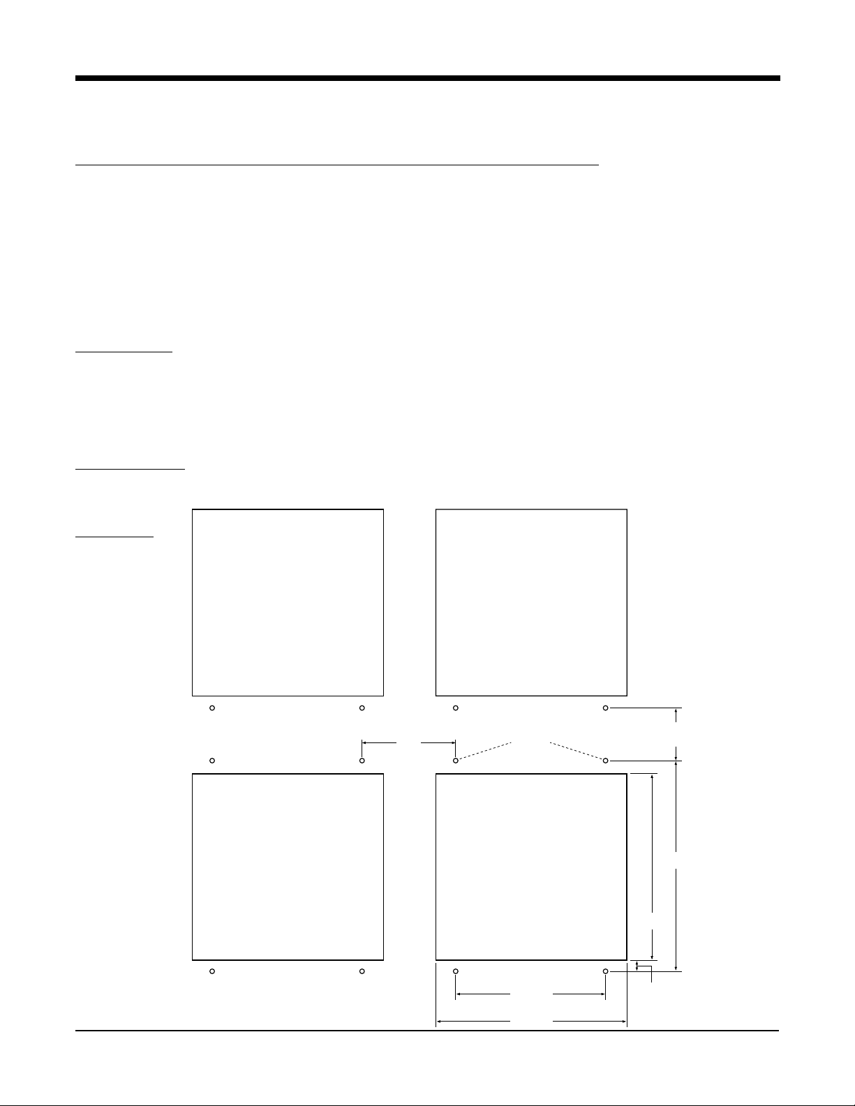
2.1 MOUNTING (Panel and Surface described below, pipe - to be determined)
Figure 2-1A and 2-1B (below and page 2) shows an installation view and physical dimensions for a panel
mounted instrument. The panel where the instrument will be mounted must provide rigid support for the approximately 25 pound instrument. Adjacent instruments may be mounted within a minimum of 2 inches horizontally
and 1 inch vertically, providing that proper panel support is supplied.
Panel Mounting Hardware Required: (not provided with instrument)
(4) #10 flat head bolts with nuts
(4) lock washers
Panel Mounting
1. Cut panel opening to the dimensions illustrated in Figure 2-1A (below).
2. Pre-drill four 3/16 dia. holes for mounting or use the drill template molded into the case after inserting the
instrument into the panel.
3. Insert the instrument in the panel opening. Firmly fasten the instrument to the panel using the nuts, bolts and
lock washers.
Surface Mounting
Install the mounting brackets, ordered separately, on the vertical sides of instrument housing. Use the brackets to
fasten the instrument to the surface. Hardware recommended - #10-24 SCRs.
FIGURE 2-1A
(MIN. HORZ. SPACING)
6.156"
(156.36mm)
3/16" DIA.
(MIN. VERT. SPACING)
3.600"
(91.44mm)
14.180"
(360.17mm)
12.700"
(322.58mm)
Section 2
2-1
10.000"
(254.00mm)
12.700"
(322.58mm)
0.7"
(17.78mm)
Edition 3
Rev G
Page 21
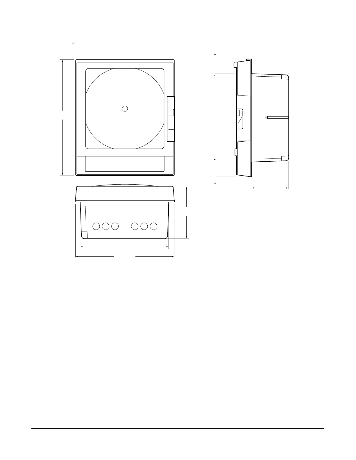
FIGURE 2-1B
g
2.12"
(53.85mm)
17.04"
(432.82mm)
EC1
EC5
EC2 EC3
EC6
EC4
7.747"
(196.77mm)
12.60"
(320.04mm)
2.044"
(58.93mm)
5.24"
(133.10mm)
12.600"
(320.04mm)
14.12"
(358.65mm)
Edition 3
Rev G
2-2
Section 2
Page 22

2.2 PREP ARATION FOR WIRING
This product is in conformity with the protection requirements of EU Council Directive 89/336EEC on the approximation of the laws of the Member States relating to electromagnetic compatibility. The factory cannot accept
responsibility for any failure to satisfy the protection requirements resulting from a non-recommended modification
of this product.
Electrical noise is a phenomenon typical of industrial environments. The following are guidelines that must be
followed to minimize the effect of noise upon any instrumentation.
Installation Considerations
Listed below are some of the common sources of electrical noise in the industrial environment:
• Ignition Transformers
• Arc Welders
• Mechanical contact relay(s)
• Solenoids
Before using any instrument near the devices listed, the instructions below should be followed:
1. If the instrument is to be mounted in the same panel as any of the listed devices, separate them by the largest
distance possible. For maximum electrical noise reduction, the noise generating devices should be mounted
in a separate enclosure.
2. If possible, eliminate mechanical contact relay(s) and replace with solid state relays. If a mechanical relay
being powered by an instrument output device cannot be replaced, a solid state relay can be used to isolate
the instrument.
3. A separate isolation transformer to feed only instrumentation should be considered. The transformer can
isolate the instrument from noise found on the AC power input.
4. If the instrument is being installed on existing equipment, the wiring in the area should be checked to insure
that good practices have been followed.
AC Power Wiring
Earth Ground
The instrument includes noise suppressing components that require an earth ground connection to function. To
verify that a good earth ground is being attached, make a resistance check from the instrument chassis to the
nearest metal water pipe or proven earth ground. This reading should not exceed 100 ohms. Each instrument
should have a dedicated earth ground. Do not chain link multiple instrument ground wires.
Neutral (For 115 VAC)
It is good practice to assure that the AC neutral is at or near ground potential. To verify this, a voltmeter check
between neutral and ground should be performed. On the AC range, the reading should not be more than 50
millivolts. If it is greater than this amount, the secondary of the AC transformer supplying the instrument should
be checked by an electrician. A proper neutral will help ensure maximum performance from the instrument.
Wire Isolation/Segregation
The instrument is designed to promote proper separation of the wiring groups that connect to the instrument. The
AC power wire terminals are located near the bottom of the power supply board. The analog signal terminals are
located near the bottom of the instrument boards. Maintain this separation of the wires to insure the best protection from electrical noise. If the wires need to be run parallel with any other wiring type(s), maintain a minimum 6
inch space between the wires. If wires must cross each other, do so at 90 degrees to minimize the contact with
each other and reduce cross talk. Cross talk is due to the electro magnetic field induced by a wire as current
passes through it.
Section 2
2-3
Edition 3
Rev G
Page 23
Use of Shielded Cable
Shielded cable helps eliminate electrical noise being induced on the wires. All analog signals should be run with
shielded cable. Connection lead length should be kept as short as possible, keeping the wires protected by the
shielding. The shield should be grounded at one end only. The preferred grounding location is at the sensor,
transmitter or transducer.
Noise Suppression at the Source
Usually, when good wiring practices are followed, no further noise protection is necessary. Sometimes in severe
electrical environments, the amount of noise is so great that it has to be suppressed at the source. Many manufacturers of relays, contactors, etc. supply "surge suppressors" which mount on the noise source.
For those devices that do not have surge suppressors supplied, RC (resistance capacitance) networks and/or
MOV (metal oxide varistors) may be added.
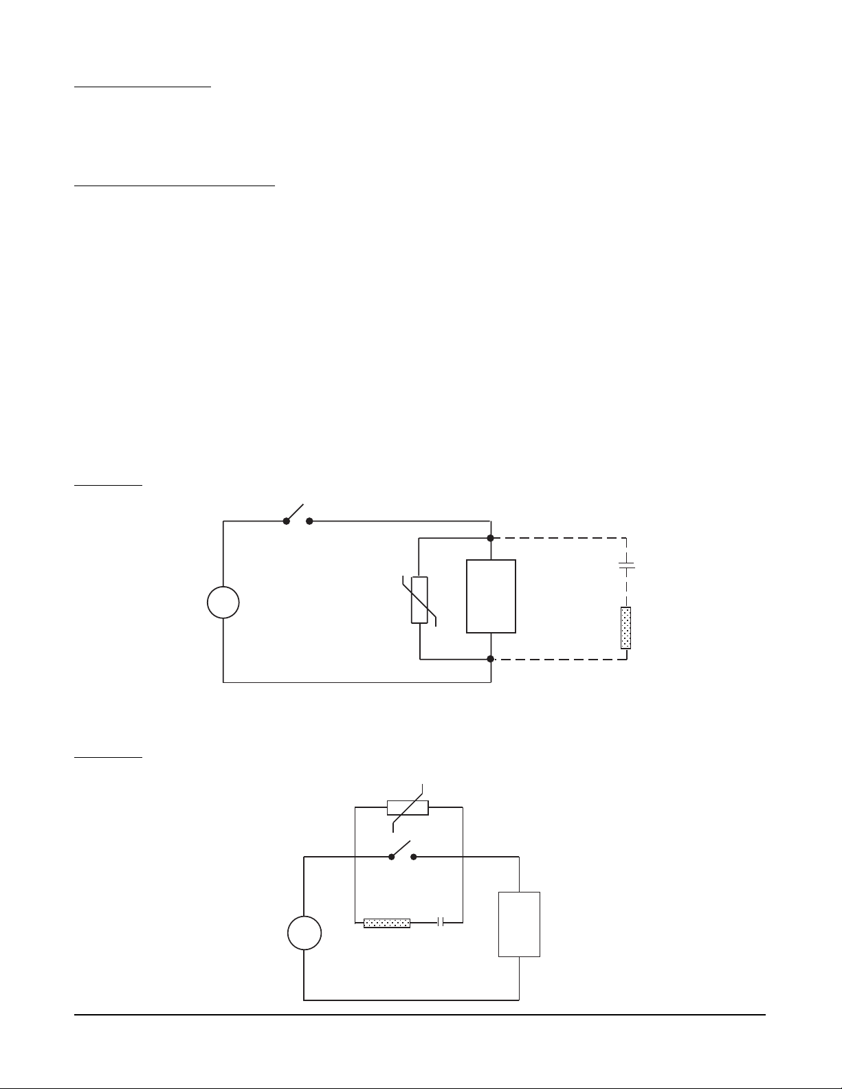
Inductive Coils - MOV's are recommended for transient suppression in inductive coils connected in parallel and as
close as possible to the coil. See Figure 2-2 (below). Additional protection may be provided by adding an RC
network across the MOV.
Contacts - Arcing may occur across contacts when the contact opens and closes. This results in electrical noise
as well as damage to the contacts. Connecting a RC network properly sized can eliminate this arc.
For circuits up to 3 amps, a combination of a 47 ohm resistor and a 0.1 microfarad capacitor (1000 volts) is
recommended. For circuits from 3 to 5 amps, connect 2 of these in parallel. See Figure 2-3 (below).
FIGURE 2-2
FIGURE 2-3
A.C.
A.C.
MOV
R
MOV
0.5
mfd
C
1000V
Inductive
Load
220
R
ohms
115V 1/4W
230V 1W
Inductive
C
Load
Edition 3
Rev G
2-4
Section 2
Page 24

Sensor Placement (Thermocouple or RTD)
Thermocouple lead resistance should not exceed 300 ohms. If this is exceeded, instrument accuracy could be
affected.
Two wire RTD's should be used only with lead lengths less than 10 feet.
If the temperature probe is to be subjected to corrosive or abrasive conditions, it should be protected by the
appropriate thermowell. The probe should be positioned to reflect true process temperature:
In liquid media - the most agitated area
In air - the best circulated area
Section 2
2-5
Edition 3
Rev G
Page 25
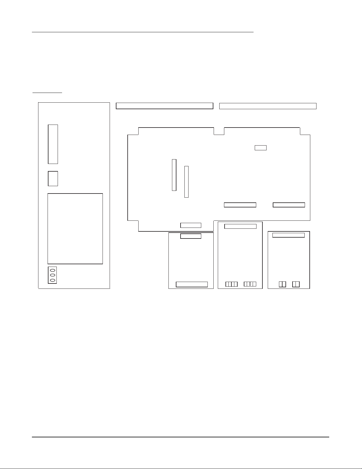
2.3 WIRING CONNECTIONS - INPUTS
All wiring connections are typically made to the instrument at the time of installation. Connections should be
made at the terminal blocks, one 14 gauge wire maximum, using copper conductors except for thermocouple
inputs. See Figure 2-4 (below) for the terminal block locations. The recommended torque for the AC Mains
connector on the power supply board is 113oz-ins and the recommended torque for all other connectors in the
unit is 85oz-ins.
FIGURE 2-4
TRANSMITTER POWER SUPPLY BOARD
COMMUNICATIONS BOARD
J1
J4
J3
MOTHER BOARD
J5
POWER
J6
Conn J7
SUPPLY
BOARD
2 HIGH
RELAY
BOARD
4 HIGH
INPUT
BOARD
2 HIGH
4-20
OUTPUT
BOARD
AC
MAINS
TB1
TB1 TB2
The instrument case may have numerous conduit openings, EC1 - EC6, depending upon the number of inputs
and outputs specified (EC5 and EC6 are not included on all models). To help minimize electrical noise that may
adversely affect the operation of the instrument, do not run input and/or 4-20mA output connections through the
same conduit entry as relay or power supply connections. See Figure 2-1B (page 2-2) for conduit opening
locations.
Edition 3
Rev G
2-6
Section 2
Page 26

2.3.1 SHIPPED CONFIGURATION/JUMPER POSITIONING
Each instrument is factory shipped with all parameters set to default values. These defaults are shown in the
"display" box for each parameter in Section 4.
Jumpers are used to condition the sensor inputs. All jumpers are located on the Input Board(s). The instrument is
shipped from the factory with these jumpers configured as follows:
JU1 IF FITTED UPSCALE BREAK
JU2 Non-Contact Closure Input
JU3 T/C, mV, 0/1V, Switch, mA
JU4 IF FITTED UPSCALE BREAK
JU5 Non-Contact Closure Input
JU6 T/C, mV, 0/1V, Switch, mA
JU7 WIDE SPAN
JU8 WIDE SPAN
JU11 IF FITTED Non-RTD
JU12 IF FITTED Non-RTD
JU15 Non-mA
JU16 Non-mA
There are 2 additional jumpers per Input Board that are used for ID. These must be positioned as shown in Table
2-1 below as per their location inside the instrument. Board 1 is the bottom board.
TABLE 2-1 BOARD ID JUMPERS
Inputs
1, 3, 5, 7
JU13 JU14Board Position
Board 1
Board 2
Board 3
Board 4
Inputs
2, 4, 6, 8
If any board is removed from the instrument in a multiple stack of boards, it MUST BE installed in the correct
sequence or these jumpers MUST BE moved. If not installed correctly, calibration will be affected.
2.3.2 SENSOR BREAK and OUT-OF-RANGE DETECTION
Sensor break and out-of-range conditions are determined and handled by the software. When either occurs, the
software will drive the input value to +99999 or -99999 based upon whether SENSOR BREAK is software configured for UPSCALE or DOWN SCALE in Input Configuration. Any outputs will react accordingly. Out-of-range is
defined as being more than 5% out of the span established by RANGE LIMIT LOW and RANGE LIMIT HIGH.
For 5 or 10 Volt and Current inputs, the analog signal goes to zero when there is a sensor break, due to voltage
divider or shunt resistors. For sensor break detection to work on these input types, the INPUT RANGE LOW
(analog signal low) and/or RANGE LIMIT LOW (engineering units low) parameters must be set high enough such
that at zero volts/mA, the resultant value will be at least 5% below the span established by RANGE LIMIT LOW
and RANGE LIMIT HIGH.
Section 2
2-7
Edition 3
Rev G
Page 27

2.3.3 AC POWER CONNECTIONS
WARNING: UNIT SHOULD HAVE A POWER SWITCH OR CIRCUIT BREAKER IN CLOSE PROXIMITY OF
EQUIPMENT AND WITHIN EASY REACH OF THE OPERATOR. THE SWITCH SHALL BE MARKED AS THE
DISCONNECTING DEVICE FOR THE UNIT.
FIGURE 2-6
Connect the line voltage, hot and neutral, to L and N respectively. Connect the ground wire to the terminal
labeled G.
UNIVERSAL POWER SUPPLY
G
N
L
~
~
Edition 3
Rev G
2-8
Section 2
Page 28
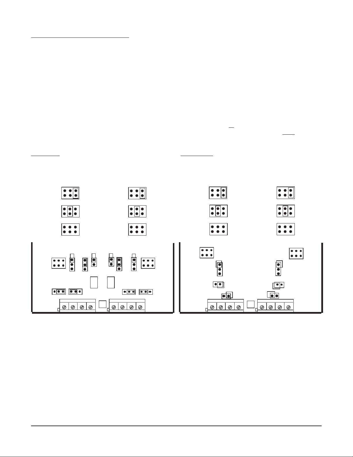
2.3.4 THERMOCOUPLE CONNECTIONS
NOTE: Up to four Input Boards may be present; stacked 4 high. Input Board 1 is the bottom board.
Two versions of Input Board s may be found, see Figure 2-7 and Figure 2-7A.
Input Board 1 is used for Input 1 and, if equipped, Input 2. Input Board 2 is used for Input 3 and Input 4, if
equipped. Input board 3 is for Input 5 and Input 6. Input Board 4 is for Input 7 and Input 8.
Connect the positive (+) leg of the thermocouple to terminal 1 and the negative (-) leg to terminal 2 on the Input
Board(s) to be T/C. Terminal block 1 (TB1) is for Input 1, 3, 5, and 7 and terminal block 2 (TB2) is for Input 2, 4, 6,
and 8.
NOTE: INPUT CONDITIONING JUMPERS MUST BE POSITIONED AS SHOWN FOR A T/C INPUT IN EITHER
FIGURE 2-7 OR 2-7A DEPENDING ON WHICH CIRCUIT BOARD IS FITTED. JUMPERS JU7/JU8 MAY BE
MOVED TO THE NARROW SPAN POSITION FOR BETTER RESOLUTION IF THE MAXIMUM TEMPERATURE DOES NOT EXCEED THE UPPER SPAN LIMIT AS SHOWN IN APPENDIX B, PAGE B-1, AND THE
THERMOCOUPLE BEING USED IS J, K, E, or N ONLY.
FIGURE 2-7 FIGURE 2-7A
INPUT 1, 3, 5, 7
JU7
INPUT
SPAN
INPUT 2, 4, 6, 8
JU8
NARROW
T, R, S, B
T/C
WIDE
NOT USED
JU15 JU16
JU8
TB2
TB1
JU7
JU11
JU3 JU1
JU2
U6
JU4 JU6
JU5 JU12
++--
11
NOTE: Terminal Block 1, Terminal 1 is on the RIGHT,
Terminal Block 2, Terminal 1 is on the LEFT.
INPUT 1, 3, 5, 7
JU7
JU7
JU3
JU2
JU15
TB1
INPUT
SPAN
NARROW
T, R, S, B
T/C
WIDE
NOT USED
++--
U1
INPUT 2, 4, 6, 8
JU8
JU6
JU5
JU16
11
JU8
TB2
Section 2
2-9
Edition 3
Rev G
Page 29
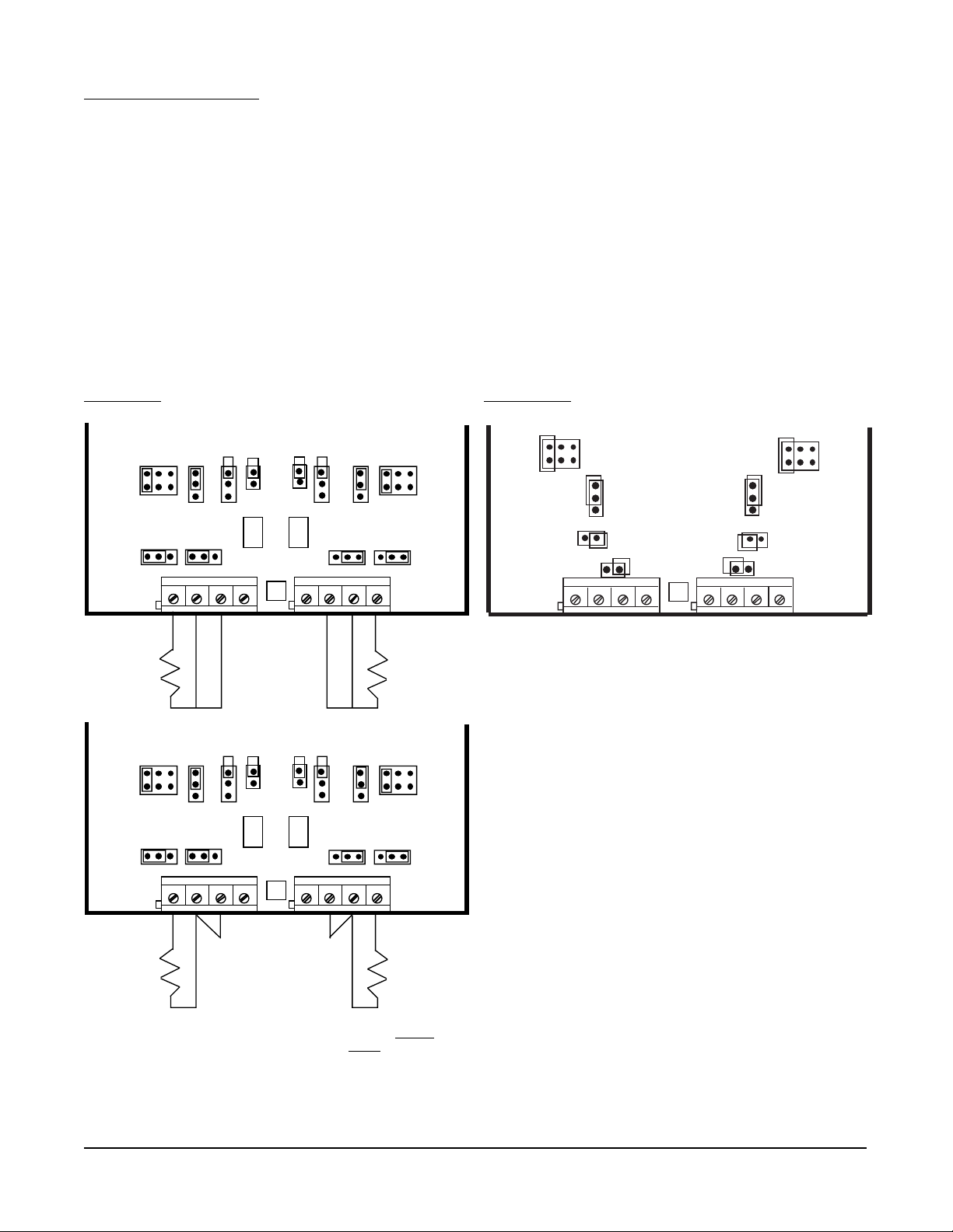
2.3.5 RTD CONNECTIONS
Note: Up to four Input Boards may be present; stacked 4 high. Input Board 1 is the bottom board. Two
versions of Input Board s may be found, see Figure 2-8 and Figure 2-8A.
Input Board 1 is used for Input 1 and, if equipped, Input 2. Input Board 2 is used for Input 3 and Input 4, if
equipped. Input Board 3 is for Input 5 and Input 6. Input Board 4 is for Input 7 and Input 8.
Connect 2 wire RTD inputs to terminals 3 and 4 on the Input Board(s) to be RTD. Install a jumper between
terminals 2 and 3. Terminal block 1 (TB1) is Input 1, 3, 5 and 7 and terminal block 2 (TB2) is Input 2, 4, 6, and 8.
Connect 3 wire RTD inputs to terminals 2, 3 and 4 (common legs on terminals 2 and 3) on the Input Board(s) to
be RTD. Terminal block 1 (TB1) is Input 1, 3, 5, and 7 and terminal block 2 (TB2) is Input 2, 4, 6, and 8.
NOTE: INPUT CONDITIONING JUMPERS MUST BE POSITIONED AS SHOWN FOR AN RTD INPUT IN
EITHER FIGURE 2-8 OR 2-8A DEPENDING ON WHICH CIRCUIT BOARD IS FITTED.
FIGURE 2-8 FIGURE 2-8A
JU15 JU16
TB1
TB1
JU7
JU11
JU7
JU11
JU3 JU1
JU2
JU3 JU1
JU2
U6
3 WIRE RTD
JU15 JU16
U6
JU4 JU6
++--
11
JU4 JU6
++--
11
JU8
JU5 JU12
JU8
JU5 JU12
TB2
TB2
TB1
JU7
JU2
JU15
JU3
JU8
JU6
JU5
++--
U1
JU16
11
TB2
JUMPER
(Customer Supplied)
2 WIRE RTD
NOTE: Terminal Block 1, Terminal 1 is on the RIGHT,
Terminal Block 2, Terminal 1 is on the
LEFT.
Edition 3
Rev G
2-10
Section 2
Page 30
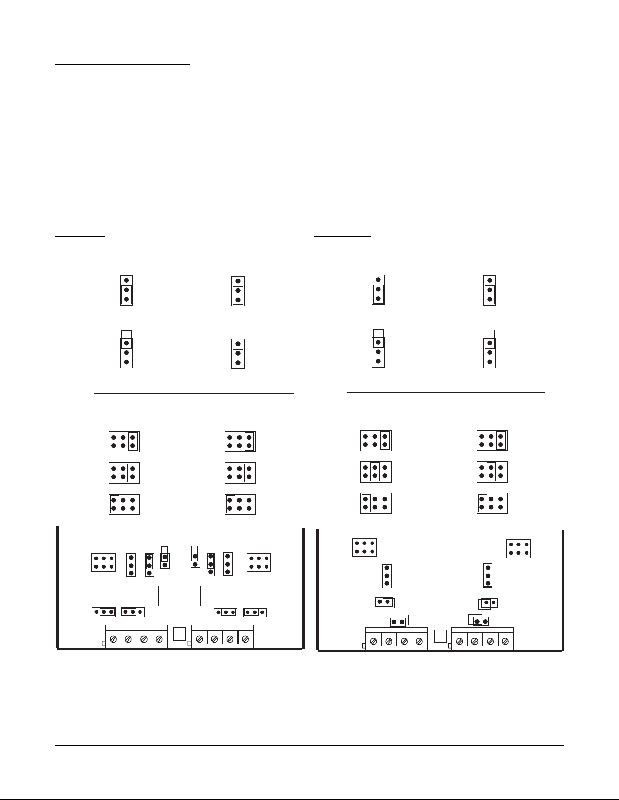
2.3.6 VOLTAGE CONNECTIONS
Note: Up to four Input Boards may be present; stacked 4 high. Input Board 1 is the bottom board. Two
versions of Input Board s may be found, see Figure 2-9 and Figure 2-9A.
Input Board 1 is used for Input 1 and, if equipped, Input 2. Input Board 2 is used for Input 3 and Input 4, if
equipped. Input Board 3 is for Input 5 and Input 6. Input Board 4 is for Input 7 and Input 8.
Connect positive (+) leg to terminal 1 and negative (-) leg to terminal 2 on the Input Board(s) to be volt input.
Terminal block 1 (TB1) is Input 1, 3,5 and 7 and terminal block 2 (TB2) is Input 2, 4, 6, and 8.
NOTE: INPUT CONDITIONING JUMPERS MUST BE POSITIONED AS SHOWN FOR VOLT INPUT IN EITHER
FIGURE 2-8 OR 2-8A DEPENDING ON WHICH CIRCUIT BOARD IS FITTED. ALSO NOTE: THERE IS NO
SENSOR BREAK DETECTION FOR ZERO BASED VOLT INPUTS. EXAMPLE: 0-5V.
FIGURE 2-9 FIGURE 2-9A
JU3
0/10V
0/5V
0/1V &mV
INPUT 1, 3, 5, 7
JU7
INPUT
SPAN
NARROW
0/25 mV
WIDE
0/100mV
LOW
VOLT
JU15 JU16
JU6
0/10V
0/5V
0/1V &mV
INPUT 2, 4, 6, 8
JU8
JU3
0/10V
0/5V
0/1V &mV
INPUT 1, 3, 5, 7
JU7
INPUT
SPAN
NARROW
0/25 mV
WIDE
0/100mV
LOW
VOLT
JU6
0/10V
0/5V
0/1V &mV
INPUT 2, 4, 6, 8
JU8
TB1
JU7
JU11
JU3
JU2
JU1
JU4
JU6
JU5 JU12
++--
U6
11
NOTE: Terminal Block 1, Terminal 1 is on the RIGHT,
Terminal Block 2, Terminal 1 is on the LEFT.
Section 2
JU8
TB2
2-11
TB1
JU7
JU2
JU15
JU3
JU8
JU6
JU5
++--
U1
JU16
11
TB2
Edition 3
Rev G
Page 31

2.3.7 CURRENT CONNECTIONS
Note: Up to four Input Boards may be present; stacked 4 high. Input Board 1 is the bottom board. Two
versions of Input Board s may be found, see Figure 2-10 and Figure 2-10A.
Input Board 1 is used for Input 1 and, if equipped, Input 2. Input Board 2 is used for Input 3 and Input 4, if
equipped. Input Board 3 is for Input 5 and Input 6. Input Board 4 is for Input 7 and Input 8.
Connect positive (+) leg to terminal 1 and connect negative (-) leg to terminal 2 on the Input Board(s) to be
current input. Terminal block 1 (TB1) is Input 1, 3, 5, and 7 and terminal block 2 (TB2) is Input 2, 4, 6, and 8.
Installation of an appropriate shunt resistor is NOT REQUIRED. Positioning JU15/16 properly connects the
appropriate shunt resistor that is populated on the Input Board.
NOTE: INPUT CONDITIONING JUMPERS MUST BE POSITIONED AS SHOWN FOR CURRENT INPUT IN
EITHER FIGURE 2-8 OR 2-8A DEPENDING ON WHICH CIRCUIT BOARD IS FITTED. ALSO NOTE: THERE
IS NO SENSOR BREAK DETECTION FOR ZERO BASED CURRENT INPUTS. EXAMPLE: 0-20MA.
FIGURE 2-10 FIGURE 2-10A
JU16
JU15
TB1
JU7
JU11
JU3 JU1
JU2
U6
JU4 JU6
++--
11
JU8
JU5 JU12
TB2
TB1
JU7
JU2
JU15
JU3
JU6
++--
U1
11
JU8
JU5
JU16
TB2
NOTE: Terminal Block 1, Terminal 1 is on the RIGHT,
Terminal Block 2, Terminal 1 is on the LEFT.
Edition 3
Rev G
2-12
Section 2
Page 32

2.3.8 SWITCH INPUT CONNECTIONS
Note: Up to four Input Boards may be present; stacked 4 high. Input Board 1 is the bottom board. Two
versions of Input Board s may be found, see Figure 2-10 and Figure 2-10A.
Input Board 1 is used for Input 1 and, if equipped, Input 2. Input Board 2 is used for Input 3 and Input 4, if
equipped. Input Board 3 is for Input 5 and Input 6. Input Board 4 is for Input 7 and Input 8.
Connect one leg to terminal 1 and connect the other leg to terminal 2 on the Input Board(s) to be switch input.
Terminal block 1 (TB1) is Input 1, 3, 5, and 7 and terminal block 2 (TB2) is Input 2, 4, 6, and 8.
NOTE: INPUT CONDITIONING JUMPERS MUST BE POSITIONED AS SHOWN FOR SWITCH INPUT IN
EITHER FIGURE 2-8 OR 2-8A DEPENDING ON WHICH CIRCUIT BOARD IS FITTED.
FIGURE 2-11 FIGURE 2-11A
JU15 JU16
JU7
JU8
JU8
TB2
TB1
JU7
JU11
JU3 JU1
JU2
U6
JU4 JU6
JU5 JU12
++--
11
NOTE: Terminal Block 1, Terminal 1 is on the RIGHT,
Terminal Block 2, Terminal 1 is on the LEFT.
TB1
JU2
JU15
JU3
JU6
JU5
++--
U1
JU16
11
TB2
Section 2
2-13
Edition 3
Rev G
Page 33

2.4 WIRING CONNECTIONS - OUTPUTS
Relay output(s), if provided, may be assigned to any actuator, which includes alarms and/or optional control
capability. Current output(s), if provided, may be assigned to any analog value, which includes derived and
process values for retransmission or control. Assignment of the function is accomplished in Configuration.
2.4.1 SPDT RELAY OUTPUT
Note: Up to two Boards may be present; stacked 2 high. Board 1 is the bottom board.
SPDT and/or SSR driver outputs is/are designated as Relay 1 through Relay 8. Relay 1 through Relay 4 are
located on Board 1 and Relay 5 through Relay 8 (if provided) are located on Board 2. See Figure 2-4, page 2-6.
Connections are made as shown. Terminal connections are made using TB1 thru TB4, Relay 1 thru Relay 4
respectively.
FIGURE 2-12
TB1 TB2 TB3 TB4
N
N
C
O
C
LOAD
P
O
W
E
R
2.4.2 SSR DRIVER OUTPUT
Note: Up to two Boards may be present; stacked 2 high. Board 1 is the bottom board.
Connections are made as shown. Terminal connections are made using TB1 thru TB4, Relay 1 thru Relay 4
respectively.
FIGURE 2-13
TB1 TB2 TB3 TB4
1
+-
Edition 3
Rev G
2-14
SSR
+
Section 2
Page 34

2.4.3 CURRENT OUTPUT
Note: Up to two boards may be present, stacked 2 high. Board 1 is the bottom board. Non-isolated and
isolated outputs are available.
Non-isolated
Non-isolated current outputs are designated as current output 1 through current output 2. Current output 1 is
located on Board 1 and Current Output 2 is located on Board 2.
Connections are made as shown. Terminal connections are made using TB1, terminal 1 is positive and terminal 2
is negative.
FIGURE 2-14
TB1
12
+
-
LOAD
+
Isolated
Isolated current outputs are designated current output 1 through current output 4. Current output 1, and if specified, current output 2, are located on board 1. Current outputs 3 and 4, if specified, are located on board 2.
Connections are made as shown. Terminal connections are made using TB1 (output 1 and 3), terminal 1 is
positive and terminal 2 is negative, and TB2 (output 2 and 4), terminal 1 is positive and terminal 2 is negative.
-
FIGURE 2-14B
TB1 TB2
1 2 1 2
Load
+ -
+ - + -
Load
+ -
Section 2
2-15
Edition 3
Rev G
Page 35

2.4.4 24VDC TRANSMITTER POWER SUPPLY
Note: Up to four transmitter power supplies may be present. One transmitter can provide up to 25mA of
current at 24 VDC.
Transmitter outputs are designated as Transmitter Output 1 through Transmitter Output 4. Transmitter Output 1 is
at TB1, Transmitter Output 2 is at TB2, Transmitter Output 3 is at TB3 and Transmitter Output 4 is at TB4.
If an isolated 24 VDC regulated transmitter power supply has been specified, the connections should be made as
shown.
FIGURE 2-15A
TBX
12
+
-
+
-
INPUT
2 Wire
Transmitter
12
+
-
2.4.5 COMMUNICATIONS
The connections should be made as shown: Terminal block TB1 is used for RS-232 (Figure 2-15B) and terminal
block TB3 is used for RS-485 (Figure 2-15c). Jumpers JP1 and JP3 must be positioned as shown.
FIGURE 2-15B
RS-232
TB1
JP1
Edition 3
Rev G
Rx
Tx
Grnd
JP3
2-16
Section 2
Page 36

FIGURE 2-15C
RS-485
TB3
B
A
Towards
Computer
JP1
JP3
Network
Continuation
(If Applicable)
Section 2
2-17
Edition 3
Rev G
Page 37

Section 3 - The Basics of Recorder Operation
3.1 POWER-UP
After proper installation, the following will occur when power is applied:
• All segments in the vacuum fluorescent display will light, then
• All the display LEDs will light, then
• The instrument tag and the current time and date will appear.
When completed, the instrument begins normal display mode as configured in Display Programming and configu-
ration.
3.2 INSTRUMENT MODES
The instrument incorporates a multilevel prompting scheme. The Display, Chart and Scroll keys are used to gain
access to each of the three prompting sections of the unit. When the instrument is not in one of the prompt
sections, it is considered to be in the Normal Display mode.
3.2.1 NORMAL DISPLAY
The Normal Display is the normal operator mode for the recorder and display. In Normal Display, the instrument
can provide various displays of Instrument Tag/Time/Date, Input Values, Derived Values, Process Values, and
other values that may be added to the Display Sequence in Configuration. In Normal Display the instrument may
be in Sequential (automatic advance) or Continuous (manual advance) display mode.
3.2.2 DISPLA Y PROMPTS
The Display Prompts provides access to all display related configuration functions and operator inputs. The
Display Prompts section contains only one level.
3.2.3 CHART PROMPTS
The Chart Prompts provides access to all chart related configuration functions and also the prompts for changing
the chart.
The Chart Prompts section contains two levels. With CHART CONFIGURATION displayed, the Down Arrow key
will access that section of prompts, which will be one level down. While in CHART CONFIGURATION, the Scroll
and Left Arrow keys will move through the parameter choices, and the Up Arrow key will return to the previous
level, which will be one level up.
3.2.4 SYSTEM PROMPTS
The Select System Prompts provides access to alarm settings, enables/passwords, configuration/setup, test,
calibration, etc.
The System Prompts section contains up to two levels. For example, with CONFIGURATION displayed, the
Down Arrow key will access the next level of prompts, where INPUTS can be selected. With INPUTS displayed,
the Down Arrow key will access the next level of prompts, where the input parameters can be accessed. Pressing
the Up Arrow key would return to the previous level, INPUTS, and pressing the Up Arrow key again would return
to the previous level, CONFIGURATION, and pressing the UP Arrow key again would return to the Normal Display
mode.
Section 3
3-1
Edition 3
Rev G
Page 38

3.3 KEYPAD FUNCTION
FIGURE 3-1
2
1
4
3
5
8
7
6
3.3.1 DISPLA Y KEY
(DISP)
While in Normal Display, the Display key initiates the Display Prompts and is used to step through the Display
Prompts.
3.3.2 CHART KEY
(CHART)
While in Normal Display, the Chart key initiates the Chart Prompts and is used to step through the Chart Prompts.
3.3.3 SCROLL KEY
While in Normal Display, the Scroll key initiates the System Prompts. While in any prompt section, the Scroll key
advances through the choices of other prompt sections or parameters and settings, at the current level. The
Scroll key is also used to move the cursor to the right while in Modify.
3.3.4 ARROW KEYS
• While in Normal Display with the Sequential Display active, the arrow keys will cause no action.
• While in Normal Display with the Continuous Display active, the Up or Down Arrow keys will step backward or
forward through items in the Display Sequence.
• While in any prompt section the Left Arrow and Scroll keys will step backward and forward through the
selections at that level. The selections wrap around at the ends. The Down Arrow key steps down (or forward)
one level. The Up Arrow key steps up (or backward) one level. If the prompting is at the top (or first) level, the
Up Arrow key will return the unit to Normal Display.
• The Arrow keys repeat, when held down, every half second after the first second.
• The unit remembers the path taken through the System and Display prompts. That is, by returning to Normal
Display by successive depressions of the Up Arrow key, the operator can return to the same point by entering
the corresponding prompts section and successive depressions of the Down Arrow key.
3.3.5 RESET KEY
(RESET - special key located on lower left)
While in a prompt section, the Reset key returns the unit to Normal Display and resets the path pointers to the
initial conditions.
3.3.6 ESCAPE KEY
(ESC),
MODIFY KEY
(MOD),
ENTER KEY
(ENTER)
• While a modifiable parameter description and its setting are displayed, pressing the MOD key places the unit in
Modify where the setting can be modified or changed.
• Pressing the ESC key will exit Modify and the original value will be displayed, no change being made to it.
• Pressing the ENTER key will exit Modify and the new value will be displayed and entered into memory.
3.3.7 SPECIAL KEYS
(five keys located below the display)
While in the Multiple Choice Selection, the Special keys are used to select 1 of up to 5 choices from a choice line
displayed directly above each key.
Rev G
3-2
Section 3Edition 3
Page 39

3.4 CHANGING PARAMETER SETTINGS - MODIFY
There are three types of parameters in the instrument: values (numbers), text strings (groups of characters), and
choices (selections made by picking one of a group of displayed descriptions).
With a modifiable parameter description and its setting displayed, pressing the MOD key places the unit in
Modify where the setting can be modified.
3.4.1 CHANGING V ALUES
If the setting is a value (number), the cursor will be positioned on the right-most digit. The LEFT ARROW and
SCROLL keys will move the cursor left or right. The UP and DOWN keys will increment or decrement the value
with rollover and rollunder through all digits to the left of the cursor. Pressing the ESC key exits Modify, no
change being made to the original value. Pressing the ENTER key exits Modify and the new value will be
displayed and entered into memory.
3.4.2 CHANGING TEXT
There are two ways to change or modify text. The first, Character Modify, is accessed by the initial pressing of
the MOD key, and the second, Character Selection, is accessed by pressing the MOD key while being in the
Character Modify mode. Each has its benefits, and you may prefer to use one or both methods, depending on
the modification to be made. Pressing the RESET key after pressing the MOD key will clear all characters from
the curser to the right.
• If the setting is text ( e.g. units, tag, etc.), the text will be left justified and the cursor will be positioned on the
left-most character. The LEFT ARROW and SCROLL keys will move the cursor left or right.
• In Character Modify, the UP and DOWN ARROW keys change the character by scrolling through a list or string
of available characters. The LEFT ARROW and SCROLL keys will move the cursor left and right to allow changing another character. Pressing the MOD key enters Character Selection. Pressing the ESC key exits Modify, no
change being made to the string. Pressing the ENTER key exits Modify and the new string will be displayed and
entered into memory.
• In Character Selection, depressing the MOD key twice will initiate Character Selection. The character to be
changed (on the lower line) will be replaced by the "block" character (all dots lit), and the upper display line will
show a character selection line, instead of the parameter description. The character selection line which contains
the current character will be displayed with the cursor positioned on the current character. The LEFT ARROW
and SCROLL keys will move the cursor left and right on the current character selection line. The UP and DOWN
ARROW keys will change the line of characters displayed for selection. Once the cursor is positioned on the
desired character, pressing the MOD key will store the desired character in the lower line, the "block" character
will move to the next position on the second line, and the character selection line which contains the next character will be displayed with the cursor positioned on that character.
• While in Character Selection, pressing the ESC key exits Character Selection and returns the unit to Character
Modify where selection of another character may be made or pressing the ESC key again exits Modify.
• While in Character Selection, pressing the ENTER key after modifying a character will exit Character Selection
and the new string will be displayed and entered into memory.
3.4.3 CHANGING CHOICES
• If the setting is a YES/NO choice, the YES/NO choice line will be displayed and the current choice will blink.
The LEFT ARROW and SCROLL keys will switch the selection between YES and NO. Selecting the choice and
pressing ENTER will exit Modify and the new setting will be displayed and entered into memory. Some YES/NO
parameter choices are initialized to NO. When changed to YES, the unit may automatically advance to the next
parameter upon depression of the ENTER key.
(Continued on next page)
Section 3
3-3
Edition 3
Rev G
Page 40

• If the setting is one of a list of choices, the choice line containing the current choice will be displayed and the
current choice will blink. If multiple choices are displayed, the LEFT ARROW or SCROLL keys will move the
selection to the left or right. If all choices are not displayed at once, due to multiple choice lines, the UP ARROW
key will step backward to the previous choice line, or the DOWN ARROW key will step forward to the next choice
line. Pressing the ESC key will exit Modify and the original setting will be displayed, no change being made to it.
Pressing the ENTER key will exit Modify and the new setting will be displayed and entered into memory.
• A choice line may offer 1 through 5 choices. Pressing the Special key located directly below the desired choice,
will select and enter that choice into memory.
3.4.4 COPY/INITIALIZE
A COPY/INITIALIZE capability is available with some parameter sections. If COPY is selected, the unit automatically goes into Modify on its associated value and uses its associated number as an index and copies data from
one set of elements into the current set of elements. If the associated number is set to zero, the factory default
values are stored into the selected set of elements (INITIALIZE). The COPY function applies to all parameter
entries following it until the next non-parameter entry.
3.4.5 P ASSWORDS
Where PASSWORDS apply, they are not displayed if the current value of the password is zero. If PASSWORDS
are not zero, and the value is set to the correct password, the unit automatically proceeds to the next parameter
entry. If PASSWORDS are not zero, and the value is set to the incorrect password, the message "INVALID
PASSWORD" will appear in the upper display.
3.4.6 ENABLES
If Chart Prompts is DISABLED, when the CHART key is pressed, the message "CHART KEY DISABLED" will
appear in the lower display. If Display Prompts is DISABLED, when the DISP key is pressed, "DISPLAY KEY
DISABLED" will appear in the lower display. If other parameters are DISABLED, their corresponding prompts will
not be displayed.
3.5 THE DISPLA Y
During normal operation, the display shows data according to the setup determined by the settings in Display and
Configuration prompts.
The display has 2 lines of 20 characters with 8 status indicators.
The display may be configured as continuous or sequential, as well as 1 value at a time, 2 values at a time, or 4
PVs at a time. Refer to Section 3.7 for details.
3.6 GENERAL
After completing installation and wiring of the instrument, the configuration procedures must be performed to
prepare the instrument for operation on the intended application. The procedures include selecting specific
prompts/parameters, entering data and possible jumper positioning. Once properly configured the instrument will
retain the selections in memory. Not all selections are applicable for every recorder.
Note: Before configuring, it is recommended that the Software Reference/Record Sheets (found at the
end of this section) be completely filled in.
Parameter selections and data entry are made via the keypad. To ease configuration and operation, user entered
data has been divided up into three sections referred to as Main Prompts. The three are: System, Display, and
Chart. Each prompt contains different type of data; chart for the chart, Display for the Display, and System, as
follows:
CONFIGURATION--ACTION TIME SETTINGS--ALARM SETTINGS--ENABLES/PASSWORDS--TEST-CALIBRATION--MODEL/REV
3-4
Rev G
Section 3Edition 3
Page 41

ACTION TIME Selections made in action time settings are used to generate actuators that are true/false
SETTINGS based on times and/or dates.
ALARM SETTING Selections made in alarm settings determine the setpoint of each alarm configured.
ENABLES/ Selections made in enables/passwords provide means of enabling or disabling certain
PASSWORDS prompts or selections AND provides additional security with the use of 6 digit passwords
restricting access to Chart, Display, Enables/Passwords and MAIN Prompts
selections.
CONFIGURATION Selections made in configuration set up the instrument for proper operation.
TEST Routines used to test the relays and chart.
CALIBRATION Routines used to calibrate the instrument.
MODEL/REV Deciphered to determine whether certain prompts or sections are shown/displayed and
revision of the software.
3.7 DISPLAY DETAILS
The instrument will spend most of the time in Normal Display. When in Normal Display, it can provide various
displays of instrument tag, input values, simulated values, derived values, process values, and other values that
may be added to the Display Sequence in Configuration, or it may display active operator messages. In Normal
Display, the instrument can also be in one of two conditions, Sequential or Continuous Display.
The display provides upper case letters only, with a few exceptions for engineering units.
The following is the format for the instrument tag and times and dates:
tag hh - hours
hh:mm aa bb/cc/yy mm - minutes
aa - AM or PM if not 24 hour
bb - month if MM:DD:YY format
day if DD:MM:YY format
cc - day if MM:DD:YY format
month if DD:MM:YY format
yy - year
- global alarm indicator
or for the third date format
tag
hh:mm aa dd mmm yy dd - day
mmm - month in 3 character format
For Instrument tag, the "tag" is the INSTRUMENT TAG from the INSTRUMENT SETTINGS prompts section, and
for ACTION TIME SETTINGS, the "tag" is TIME 1 TAG or TIME 2 TAG from the ACTION TIME SETTINGS
prompts section.
(Continued on next page)
Section 3
3-5
Edition 3
Rev G
Page 42

The following is the "1 VAL" at a time display format for process variables:
display tag
aaaannnnnn uuuuuu aaaa - individual alarm indicators:
H = High Process Alarm
L = Low Process Alarm
R = Rate Alarm
nnnnnn - represents a number, with up to as many digits as n's shown
uuuuuu - represents the corresponding units, with up to as many characters as
u's shown
The same format applies for input, simulated, and derived variables, except that aaaa does not apply.
The following is the "2 VALS" at a time display format for process variables:
paaaannnnnn uuuuuu p - Process Variable Number
paaaannnnnn uuuuuu
The following is the "2 VALS" at a time display format for other variables:
IVm nnnnnn uuuuuu m - Input Variable Number
IVm nnnnnn uuuuuu
SVm nnnnnn uuuuuu m - Simulated Variable Number
SVm nnnnnn uuuuuu
DVmm nnnnnn uuuuuu mm - Derived Variable Number
DVmm nnnnnn uuuuuu
The following is the "4 PVS" at a time display format for process variables:
pannnnuuu pannnnuuu p - Process Variable Number
pannnnuuu pannnnuuu a - Highest Priority Active Alarm
When "4 PVS" at a time is selected, all variables except PVs will be displayed using their respective "2 VALS" at a
time format.
The following is the "1 VAL" at a time display format for totals:
display tag w w - Preset Indicator
nnnnnnnnnnn uuuuuu P - Preset Reached
To maintain a consistant value and units placement, the following is the "2 VAL" at a time display format for totals:
display tag w w - Preset Indicator
nnnnnnnnnnn uuuuuu P - Preset Reached
The number may or may not contain commas, depending on the number format selected for total values.
Operator Messages are displayed as their configured two line message, regardless of the format selected.
For contact closure inputs, the nnnnnn field will contain the text corresponding to the current state.
3-6
Rev G
Section 3Edition 3
Page 43

Whenever the display format is other than "1 VAL" at a time, the different types are not intermixed in any given
display step, consequently the second line may be blank.
SEQUENTIAL DISPLAY
With Sequential Display active, the instrument provides a sequential display of all input, simulated, derived, and
process values that have their Display Option set to "IN SEQUENTIAL MODE" or "IN BOTH MODES". The rate
of sequencing is programmable from 1 to 8 seconds.
CONTINUOUS DISPLAY
With Continuous Display active, the instrument continuously displays a single step of the Display Sequence for all
input, simulated, derived, and process values that have their Display Option set to "IN CONTINUOUS MODE" or
"IN BOTH MODES". The UP and DOWN keys will step backward or forward through the list.
3.8 CHART DETAILS
The CHART TYPE is user selectable from one of three choices:
1. RINGS/LINES/SCALES preprinted
Rings - concentric rings
Lines - time lines
Scales - scale numbers
2. RINGS AND TIME LINES preprinted
3. RINGS ONLY preprinted
The RECORDING METHOD choices, user selectable per pen are as follows, using a 24 hour rotation for example, with spokes recorded every 24 seconds.
1. INSTANTANEOUS VALUES - records the instantaneous value at 24 second intervals.
2. CONNECT THE VALUES - records the instantaneous value at 24 second intervals, but includes dots
between successive values.
3. DRAG - MIN TO MAX - records the minimum and maximum values during the 24 second interval and
includes dots between the values.
4. AVERAGE VALUES - records the average of the values during the 24 second interval.
5. CONNECT THE AVERAGES - records the average of the values during the 24 second interval, but
includes dots between successive averages.
Major time lines are printed as a series of dots, with noticeable spacing, and extend from the inner chart ring to
the outer chart ring. The number of major time lines printed on the chart is determined by the MAJOR TIME
PERIODS parameter in the CHART CONFIGURATION prompts section. The color of the major time line is
programmable.
Scale lines are printed as a series of dots, closely spaced to form a solid line, and are printed only in the area of
the chart (zone or portion of chart span) used for the respective trend line. The scale lines are printed on top of
major time lines. The number of scale lines printed on the chart is determined by the MAJOR TIME PERIODS
parameter, the number of BLANK MAJOR TIME PERIODS, and the number of trend lines being recorded. The
color of the scale line is the same as the respective trend line.
Minor time lines are printed as a series of dots, with spacing greater than major time lines and extend from the
inner chart ring to the outer chart ring. The number of minor time lines printed on the chart between the major
time lines is determined by the MINOR TIME PERIODS parameter in the CHART CONFIGURATION prompts
section and is one less than the number of periods selected.
Section 3
3-7
Edition 3
Rev G
Page 44

Trends can be zoned into two different areas to allow for higher resolution on one end of the recorded span. The
recorded area used on the chart for a trend may not necessarily use the entire area available for recording.
Engineering unit values are printed next to the corresponding scale lines. The ZONE 1 LOW DIVISION parameter in RECORDERS section of CONFIGURATION specifies the position on the chart corresponding to the
bottom of zone 1 and the ZONE 1 HIGH DIVISION parameter specifies the position on the chart corresponding to
the top of zone 1 (and the bottom of zone 2 if zone 2 is used). The ZONE 2 HIGH DIVISION parameter specifies
the position on the chart corresponding to the top of zone 2, with zero specifying that zone 2 is not used.
The SPAN 1 LOW parameter specifies the value corresponding to the bottom of zone 1 and SPAN 1 HIGH
parameter specifies the value corresponding to the top of zone 1 and bottom of zone 2 (if used). The SPAN 2
HIGH parameter specifies the value corresponding to the top of zone 2. If the zone 2 parameter is zero, zone 2
is inactive or not used.
The DIVISION parameters specify location relative to the CHART DIVISIONS parameter (or number of chart
rings), which corresponds to the usable recording span of the chart.
The SCALE INTERVAL parameters specify the number of divisions between printed scale values. The values
printed are calculated by the instrument. If the SCALE INTERVAL parameter is zero, no scale is printed, but the
recorder tag will be printed.
Values corresponding to the bottom of the recordable area are located slightly upscale so that they are printable.
Values corresponding to the top of the recordable area are located slightly downscale so that they do not interfere
with the time and date. All other values are centered vertically on the corresponding concentric circle.
The UNITS that are configured for display are printed next to the outermost scale value.
The RECORDER TAG for each recorded trend is printed underneath the outermost scale value.
The CHART TAG, time, and date are printed just beyond the recording area, at successive major time lines as
follows:
On 10" and 12" Charts:
CHART TAG TIME DA TE TIME
On 1 1" Charts:
CHART TAG DATE CHART TAG DATE
TIME TIME TIME TIME
The color of the scale line, scale values, units, and recorder tag always correspond to the trend for which they
apply.
The color of the major time lines, minor time lines, time, and date/chart tag are each programmable.
3.8.1 CHART PRINTING INTERRUPTIONS
When chart printing is interrupted momentarily, the printing resumes as though no interruption had occurred.
If the interruption lasts beyond the point at which data should have been printed, the chart will advance to the
appropriate point, printing minor and major time lines as needed, and resume trending.
If the interruption lasts long enough such that no data would be printed between successive major time divisions,
the divisions will not be printed.
When power is restored, the chart is marked with an arrow (" ê") to indicate the point of power interuption.
Rev G
3-8
Section 3Edition 3
Page 45

3.8.2 NEW CHART PRINTING REQUIREMENTS
The following ACTION ON NEW CHART options are provided:
NONE - JUST CONTINUE
PRINT RANGE LIST
PRINT SCALES
The following example illustrates the format used if PRINT RANGE LIST has been configured. This method
would be selected to reduce the time between chart installation and initial trend recording. This Range List
corresponds to the example found at the end of this section.
Line Print Description Color
1 FLOW #1 Recorder Tag Black
2 0/400 GPM Span, Units Black
3 TEMP #1 Recorder Tag Blue
4 20/120 *F NL Span, Units Blue
5 PH #1 Recorder Tag Green
6 0/14 PH NL Span, Units Green
7 ALARM #1 Recorder Tag Red
8 0/1 NL Span, Units Red
If the scale is other than a simple 0 to 100% of chart with one zone, "NL" will follow the units to indicate non
linear.
If PRINT SCALES has been configured, the instrument will proceed to print, as needed per the chart format, time
lines, scale lines, scale values, units and recorder tag for each recording pen which is configured. The time, date,
and chart tag will not be printed during this process. The chart will be advanced to the correct position for the
next time line after the completion of printing for each recording pen.
Upon completion of PRINT RANGE LIST or PRINT SCALES, if configured, the instrument is ready to begin
trending. Trending will not begin if the instrument status has been set to OFF or the chart has been stopped.
When the instrument first begins trending after a new chart has been installed, it will print, as needed per the
chart format, time lines, scale lines, scale values, units, and recorder tag for each recording pen until it reaches
the position corresponding to the current time. If the instrument status has not been set to off and the chart
has not been stopped by other than the chart being full, historical trend data will also be included. The
time, date, and chart tag will be printed during this process. At this point, the instrument will begin the normal
recording process and marks the chart on the outer ring with an arrow(" ¨") to indicate where the trend began.
3.8.3 EXAMPLE CHART
Figure 3-2 (page 3-12) illustrates the typical data presentation for a 12" chart. The "recorder" trends are referred
to by number in this illustration for black and white reproduction.
Refer to Table 3-1 (page 3-10) and Table 3-2 (page 3-11) for the corresponding recorder configuration/programming data. For this example, the instrument has four inputs as follows:
1 Raw Flow Value
2 Temperature
3 Pressure
4pH
The value recorded on Pen 1 is a derived value; flow corrected for temperature and pressure. The derived value
is also converted to a process value for alarming.
(Continued on next page)
Section 3
3-9
Edition 3
Rev G
Page 46

The value recorded on Pen 2 is the temperature, zoned to record 20 to 120 on the lower 10% of the chart, and
120 to 210 on the upper 90% of the chart.
The value recorded on Pen 3 is the pH, input 4 zoned to record 0 to 14 on the upper 70% of the chart.
The value recorded on Pen 4 is the status of alarm A11, zoned to record 0 or 1 at 70% or 80% of the chart.
Input 3, the pressure, is used in the derived value, but not recorded.
TABLE 3-1 Configure Chart Parameters
(Not all parameters are shown)
CONFIGURE CHART
CHART TYPE USED
(CHART TYPE) RINGS ONLY
CHART TAG
t t t t t t t t t t t t t t t t t t t t UNIT #1
NORMAL SPEED
(CHART SPEED) 24 HOURS
MAJOR TIME PERIODS
n n 24
MINOR TIME PERIODS
n 4
BLANK TIME PERIODS
n 2
ACTION ON NEW CHART
(NEW CHART ACTION) PRINT SCALES
Rev G
3-10
Section 3Edition 3
Page 47

TABLE 3-2 Recorder Parameters
(Not all parameters are shown)
RECORDER NUMBER 1 2 3 4
Rs RECORDER TAG
t t t t t t t t t t t t t t t t t t t t FLOW #1 TEMP #1 PH #1 ALARM #1
Rs VALUE TO RECORD
(VALUE) DV1 IV2 IV4 DV2
Rs PEN/COLOR
(PEN/COLOR) BLUE GREEN BLACK RED
RS CHART DIVISIONS
n n n 100 100 100 100
Rs ZONE 1 LOW
DIVISION n n n 0 0 30 70
Rs ZONE 1 HIGH
DIVISION n n n 100 10 100 80
Rs SPAN 1 LOW
n n n n n n n u u u u u u 0 GPM 20 F 0 PH 0
Rs SPAN 1 HIGH
n n n n n n n u u u u u u 400 GPM 120 F 14 PH 1
Rs SCALE 1 INTERVAL
n n DIVISIONS 10 10 10 10
Rs ZONE 2 HIGH
DIVISION n n n 0 100 0 0
Rs SPAN 2 HIGH
n n n n n n n u u u u u u N/A 210 F N/A N/A
Rs SCALE 2 INTERVAL
n n DIVISIONS N/A 10 N/A N/A
Rs POSITION ON ERROR
DIVISION n n n 100 100 20 90
Section 3
3-11
Edition 3
Rev G
Page 48

3.8.4 SEQUENCE OF EVENTS
11:27 PM Chart installed
11:30 PM Instrument began printing with the Chart Tag, (UNIT #1) and the trend data collected and
saved between 11:27 and 11:30, while continuing to save scanned data. Note the "¨" on the
outer ring to indicate where trending began
11:31 PM Instrument caught up to the current time and began normal trending.
11:50 PM Flow rate went into alarm.
12:20 PM Flow rate came out of alarm.
12:54 PM Recording interrupted by power failure.
1:12 PM Recording restored, "ê" marked on the chart at X:XX PM to indicate point of power interruption
and chart positioned to correct time and trending resumes.
FIGURE 3-2
Rev G
3-12
Section 3Edition 3
Page 49

3.9 GETTING STARTED
Before attempting any configuration/programming, review Sections 3.3 Keypad Function; 3.4 Changing Parameter Settings; 3.7 Display Details; 3.8 Chart Details; and Appendix C Reference Section.
Then, using the Flow Charts below, the Quick Start Procedure, page 3-14 and filled in the Software Reference/
Record Sheets, determine the prompts and parameters that will be required for proper operation of the instrument and begin the configuration and programming procedures as described in Section 4 Configuration; Section
5 Display Programming; Section 6 Chart Prompts, and if required, Section 7 Alarm Settings and Section 8 Action
Time Settings. Section 9 contains procedures for Enabling/Disabling and entering Passwords.
Appendix D may be referred to for examples of how to program/configure some prompts and parameters.
MAIN PROMPTS
CHART
PROMPTS
DISP
PROMPTS
SYSTEM
PROMPTS
* CONTROLLER ONLY
CHART
PASSWORD
DISP
PASSW ORD
SYSTEM
PASSW ORD
CONFIGURATION
CONFIG
INPUTS
CHANGE
CHART
CONTROLLER
STATE ACCESS*
ACT/TIME
SETTINGS
CONSTANTS
YES
START
CHART
NO
SETPOINTS*
ALARM
SETTINGS
CUSTOM
CURVES
SELECT
CHART
ROTATE
TUNING
PARAMETERS*
DERIVED
VARIABLES
TREND
COLLECT
SELECT
MANUAL VALUES*
ENABLES
PASSW ORDS
PROCESS
VARIABLES
CHART
SPEED
DISP
MODE
CONFIG.
CONTROLLERS*
CHART
CONFIG
DISP
FORMAT
TEST
SETPOINTS*
SEQ DISP
DURATION
CAL
RECORDERS
MODEL
REV
OPER
INPUT
TOTALIZERS
* CONTROLLER ONLY
Section 3
TIMERS LEDS
DERIVED
ACTUATORS
OPERATOR
INPUTS
RELAYS
OPERATOR
MESSAGES
CURRENT
OUTPUTS
MESSAGES
3-13
CHART
INSTRUMENT
SETTINGS
CONTROL STATE
ACCESS*
SIMULATED
VARIABLES
Edition 3
Rev G
Page 50

3.10 QUICK START PROCEDURE
This procedure can be used for starting up the recorder at the very basic level of recording inputs or to quickly
familiarize yourself with the basic configuration process. A large number of default parameters are utilized and
the default conditions are assumed. Please refer to the balance of Section 4 for important details on how to get
full use of the instruments capabilities.
To use this procedure you should have already jumper configured at least one input (see Section 2 - Installation
and Wiring), or be willing to use the factory settings of Thermocouple, Wide Span and Upscale Break protection.
The marker pen assembly should also be installed, see Section 2 for installation instructions.
Connect a sensor or input signal source to the primary input that matches the type of hardware configured on the
input board. If the input is configured as a thermocouple, you can simply install a wire between the input connections and the unit will indicate the temperature inside the instrument.
To perform Quick Start you will need to configure the Input Value, Recorder Pen, Chart, and Display.
Input Value Configuration
Step 1
From a power-up state, depress the SCROLL key until CONFIGURATION shows in the lower line display (the
upper line display will show SELECT). With CONFIGURATION in the lower line display, use the DOWN key, then
SCROLL key to select INPUTS. Press the DOWN ARROW key to display INPUT NUMBER. The INPUT NUMBER must agree with the input to be displayed and recorded. Press the MOD key, use the UP/DOWN arrows to
change the value, and the ENTER key to make the selection.
Step 2
Depress the SCROLL key twice to skip over IVx COPY/INITIALIZE. The display should show IVx DISPLAY TAG.
If you wish to enter a Display Tag, use the MOD key and then the UP/DOWN arrows or MOD key again to enter
the Character Selection, then select characters for the Tag.
Step 3
Depress the SCROLL key to advance to the display, IVx INPUT TYPE/RANGE. The default will be OFF-NO
INPUT. Select MOD to change this and SCROLL to select an input type. Press ENTER to finalize the selection.
Step 4
The Prompts displayed, after the next depression of the SCROLL key will depend on which Input Type/Range
was selected. If Thermocouple or RTD were selected, then the specific type of Thermocouple or RTD will need to
be selected. Use the MOD key to change, then the SCROLL and ENTER keys as before. Degrees C or F can
also be selected after the type of TC or RTD has been specified by pressing the LEFT ARROW or SCROLL key
to choice, then press Enter. If mA, mV, or volt was selected go to step 5, otherwise go to Step 7.
Step 5
Press the SCROLL key to INPUT RANGE LOW (default = 0) and INPUT RANGE HIGH (default = 100). These
two parameters specify the desired analog signal range (4-20mA, 0-100mV) that will be scaled to engineering
units.
Step 6
If mA, mV, or VOLT was selected, the SCROLL key will display IVx V/mA CONVERSION next. LINEAR is the
default condition. Select according to the type of signal conversion desired.
Step 7
The next display will show IVx DISPLAY UNITS. Select F, C or OTHER. If OTHER is selected, the SCROLL key
will next bring up IVx OTHER UNITS on the display. Use the MOD key, then UP/DOWN arrows and ENTER to
specify the Display Units.
Rev G
3-14
Section 3Edition 3
Page 51

Step 8
Next, the display will show IVx DECIMAL POSITION, IVx RANGE LIMIT LOW, and IVx RANGE LIMIT HIGH.
These will be used to calculate the engineering units range for volt/milliamp inputs for the Input being configured.
For Thermocouple/RTD inputs, their values establish the expected range outside of which the instrument will
consider the value "out of range". Select accordingly with the MOD, SCROLL, UP/DOWN arrows and ENTER.
Step 9
Depress the SCROLL key and skip over the rest of the Input Selections until the display shows IVx DISPLAY
OPTION. Select IN BOTH MODES for this input.
Step 10
After depressing the ENTER key, depress the UP ARROW key to get back to the previous level of CONFIGURE.
Step 11
Depress the SCROLL key until RECORDERS is displayed in the lower line display.
Step 12
Depress the DOWN ARROW key to enter the Recorder Configuration section. Depress the SCROLL key and
skip over the displays shown until the display shows Rx VALUE TO RECORD. Use the MOD and UP/DOWN
keys to select IVx where X is the input channel being configured. Press ENTER to finalize this selection.
Step 13
Depress the SCROLL key and skip over the displays until the display shows Rx SPAN 1 LOW and enter the low
end of the range of units to be recorded. In other words, what input value (in units) should represent the low end
of chart. Input this value using the MOD, UP/DOWN arrows, SCROLL and ENTER as before.
Step 14
Repeat for Rx SPAN 1 HIGH, using the input value (in units) that should represent the high end of the chart.
Note: the recorder span should normally correspond to an even multiple of one hundred units (for example 0 to
200 or 30 to 130, not 0 to 130) so the scales are convenient to read.
Step 15
Depress the UP ARROW key 3 times to return to the Normal Display.
Step 16
Depress the CHART key until SELECT and CHART CONFIGURATION appears. Press the DOWN ARROW key
to show CHART SIZE. Select the chart size being used. Press the UP ARROW key twice to return to the
Normal Display.
Step 17
Depress the CHART key again until CHANGE CHART appears. Select YES. Install the chart. Be sure to adjust
the three retaining clips according to the size chart being used. The display should show START NEW CHART.
Select YES with the LEFT ARROW key and then press ENTER.
After initializing the chart, the recorder should begin recording and displaying values for the Input Signal just
configured.
Section 3
3-15
Edition 3
Rev G
Page 52

Software Reference/Record Sheet
Configuration
INPUT
Parameter Input 1 Input 2 Input 3 Input 4
DISPLA Y T AG
INPUT TYPE/RANGE
T/C TYPE
RTD TYPE
DEG C/F
SENSOR BREAK
INPUT RANGE LOW
INPUT RANGE HIGH
PULSE RATE HIGH
COMMS ADDRESS
COMMS REGISTER
REGISTER TYPE
V/MA CONVERSION
DISPLAY UNITS
OTHER UNITS
DECIMAL POSITION
RANGE LIMIT LOW
RANGE LIMIT HIGH
EXPONENT
CUTOFF TYPE
CUTOFF V ALUE
INPUT CORRECT 1
INPUT CORRECT 2
V ALUE FILTER
DISPLAY OPTION
Upscale Downscale
Upscale Downscale
Pulse/Sec
Units
Units
@
@
Seconds
Pulse/Sec
Units
Units
@
@
Seconds
Upscale Downscale
Upscale Downscale
Pulse/Sec
Units
Units
@
@
Seconds
Pulse/Sec
Units
Units
@
@
Seconds
OPEN/1 DESCR.
CLOSED/0 DESCR.
DISPLA Y FILTER
Rev G
Seconds
3-16
Seconds
Seconds
Seconds
Section 3Edition 3
Page 53

Software Reference/Record Sheet
Configuration
INPUT
Parameter Input 5 Input 6 Input 7 Input 8
DISPLA Y T AG
INPUT TYPE/RANGE
T/C TYPE
T/C INPUT SPAN
RTD TYPE
DEG C/F
V/MA INPUT TYPE
SENSOR BREAK
INPUT RANGE LOW
INPUT RANGE HIGH
PULSE RA TE HIGH
COMMS ADDRESS
COMMS REGISTER
REGISTER TYPE
V/MA CONVERSION
DISPLAY UNITS
OTHER UNITS
DECIMAL POSITION
RANGE LIMIT LOW
RANGE LIMIT HIGH
EXPONENT
Wide Narrow
Upscale Downscale
Wide Narrow
Upscale Downscale
Pulse/Sec
Units
Units
Pulse/Sec
Units
Units
Wide Narrow
Upscale Downscale
Wide Narrow
Upscale Downscale
Pulse/Sec
Units
Units
Pulse/Sec
Units
Units
CUTOFF TYPE
CUTOFF V ALUE
INPUT CORRECT 1
INPUT CORRECT 2
V ALUE FILTER
DISPLAY OPTION
HIGH ST ATE DES
LOW ST A TE DES
DISPLA Y FILTER
Section 3
@
@
Seconds
Seconds
@
@
3-17
Seconds
Seconds
@
@
Seconds
Seconds
@
@
Seconds
Seconds
Edition 3
Rev G
Page 54

Software Reference/Record Sheet
Configuration
CONSTANTS
Parameter CV-1 CV-2 CV-3 CV-4
VALUE
Parameter CV-7 CV-8 CV-9 CV-10 CV-11 CV-12
Parameter CV-5 CV-6 CV-7 CV-8
VALUE
Parameter CV-9 CV-10 CV-11 CV-12
VALUE
Rev G
3-18
Section 3Edition 3
Page 55

Software Reference/Record Sheet
Configuration
CUSTOM CURVES
Parameter CC-1 CC-2
DECIMAL POSITION OF
INPUT
DECIMAL POSITION OF
OUTPUT
NUMBER OF POINTS
POINT PAIR 01
POINT PAIR 02
POINT PAIR 03
POINT PAIR 04
POINT PAIR 05
POINT PAIR 06
POINT PAIR 07
POINT PAIR 08
POINT PAIR 09
POINT PAIR 10
POINT PAIR 11
POINT PAIR 12
POINT PAIR 13
POINT PAIR 14
POINT PAIR 15
POINT PAIR 16
POINT PAIR 17
POINT PAIR 18
POINT PAIR 19
POINT PAIR 20
POINT PAIR 21
-->
-->
-->
-->
-->
-->
-->
-->
-->
-->
-->
-->
-->
-->
-->
-->
-->
-->
-->
-->
-->
-->
-->
-->
-->
-->
-->
-->
-->
-->
-->
-->
-->
-->
-->
-->
-->
-->
-->
-->
-->
-->
Section 3
3-19
Edition 3
Rev G
Page 56

Software Reference/Record Sheet
Configuration
CUSTOM CURVES
Parameter CC-3 CC-4
DECIMAL POSITION OF
INPUT
DECIMAL POSITION OF
OUTPUT
NUMBER OF POINTS
POINT PAIR 01
POINT PAIR 02
POINT PAIR 03
POINT PAIR 04
POINT PAIR 05
POINT PAIR 06
POINT PAIR 07
POINT PAIR 08
POINT PAIR 09
POINT PAIR 10
POINT PAIR 11
POINT PAIR 12
POINT PAIR 13
POINT PAIR 14
POINT PAIR 15
POINT PAIR 16
POINT PAIR 17
POINT PAIR 18
POINT PAIR 19
POINT PAIR 20
POINT PAIR 21
-->
-->
-->
-->
-->
-->
-->
-->
-->
-->
-->
-->
-->
-->
-->
-->
-->
-->
-->
-->
-->
-->
-->
-->
-->
-->
-->
-->
-->
-->
-->
-->
-->
-->
-->
-->
-->
-->
-->
-->
-->
-->
Rev G
3-20
Section 3Edition 3
Page 57

Software Reference/Record Sheet
Configuration
DERIVED VARIABLES
Parameter DV-1 DV-2 DV-3 DV-4
DISPLAY TAG
FUNCTION
INPUT 1
INPUT 2
INPUT 3
INPUT 4
INPUT 5
INPUT ACTUATOR
RESET ACTUA T OR
DISPLAY UNITS
UNITS DESCRIPTION
DECIMAL POSITION
VALUE FILTER
seconds
seconds
seconds
DISPLAY OPTION
DISPLAY FILTER
seconds
seconds
seconds
Parameter DV-5 DV-6 DV-7 DV-8
DISPLAY TAG
FUNCTION
INPUT 1
INPUT 2
INPUT 3
INPUT 4
INPUT 5
INPUT ACTUATOR
RESET ACTUA T OR
DISPLAY UNITS
UNITS DESCRIPTION
seconds
seconds
DECIMAL POSITION
VALUE FILTER
DISPLAY OPTION
DISPLAY FILTER
Section 3
seconds
seconds
seconds
seconds
3-21
seconds
seconds
seconds
seconds
Edition 3
Rev G
Page 58

Software Reference/Record Sheet
Configuration
DERIVED VARIABLES
Parameter DV-9 DV-10 DV-11 DV-12
DISPLAY TAG
FUNCTION
INPUT 1
INPUT 2
INPUT 3
INPUT 4
INPUT 5
INPUT ACTUATOR
RESET ACTUATOR
DISPLAY UNITS
UNITS DESCRIPTION
DECIMAL POSITION
VALUE FILTER
DISPLAY VALUE
DISPLAY FILTER
seconds
seconds
seconds
seconds
seconds
seconds
seconds
seconds
Rev G
3-22
Section 3Edition 3
Page 59

Software Reference/Record Sheet
Configuration
PROCESS VARIABLES
Parameter PV-1 PV-2 PV-3 PV-4
DISPLA Y T AG
INPUT
DISPLAY UNITS
OTHER UNITS
DECIMAL POSITION
V ALUE FILTER
DISPLAY OPTION
DISPLA Y FILTER
Ax1 ALARM TYPE
Ax1 TIME BASE
Ax1 SAMPLE PERIOD
Ax1 HYSTERESIS
Ax2 ALARM TYPE
Ax2 TIME BASE
Ax2 SAMPLE PERIOD
Ax2 HYSTERESIS
Ax3 ALARM TYPE
Ax3 TIME BASE
Ax3 SAMPLE PERIOD
Ax3 HYSTERESIS
Ax4 ALARM TYPE
Ax4 TIME BASE
seconds
seconds
seconds
seconds
seconds
seconds
seconds
seconds
seconds
seconds
seconds
seconds
seconds
seconds
seconds
seconds
seconds
seconds
seconds
seconds
Ax4 SAMPLE PERIOD
Ax4 HYSTERESIS
LOOP ALARM TIME
ALARM INHIBIT
Section 3
seconds
seconds
3-23
seconds
seconds
Edition 3
Rev G
Page 60

Software Reference/Record Sheet
Configuration
CONTROLLERS
Parameter CONTROLLER-1 CONTROLLER-2 CONTROLLER-3 CONTROLLER-4
CONTROL TYPE
OUT 1 TYPE
OUT 2 TYPE
OUT 1 HYST
OUT 2 HYST
OUT 1 % LIMIT
OUT 2 % LIMIT
OUT 1 % ERROR
OUT 2 % ERROR
OUT SLEW RATE
MANUAL ACTUA TOR
AUTO TRANSFER
MAIN SP SOURCE
REMOTE SP ACTUA T OR
REMOTE SP SOURCE
2nd SP ACTUATOR
2nd SP SOURCE
REMOTE SP RATIO
REMOTE SP BIAS
FEED FWD SOURCE
FEED FWD HIGH
FEED FWD LOW
%
%
%
%
%/MIN
OFF ON
%
%
%
%
%MIN
OFF ON
%
%
%
%
%/MIN
OFF ON
%
%
%
%
%/MIN
OFF ON
DISP SELECT SP
DISP RAMPED SP
DISP % OUTPUTS
Rev G
3-24
Section 3Edition 3
Page 61

Software Reference/Record Sheet
Configuration
CONTROL SETPOINTS
Parameter Setpoint 1 Setpoint 2 Setpoint 3 Setpoint 4
*PROMPT TEXT
DISPLAY UNITS
OTHER UNITS
DEC POSITION
UPPER LIMIT
LOWER LIMIT
DISP OPTION
Parameter Setpoint 1 Setpoint 2 Setpoint 3 Setpoint 4
*PROMPT TEXT
DISPLAY UNITS
OTHER UNITS
DEC POSITION
UPPER LIMIT
LOWER LIMIT
DISP OPTION
* If the prompt text is blank, the setpoint is disabled and the remaining prompts will not be seen. The
setpoint will also not appear in the setpoint sub-menu of the DISPLAY menu.
Section 3
3-25
Edition 3
Rev G
Page 62

Software Reference/Record Sheet
Configuration
RECORDERS
Parameter RCDR-1 RCDR-2 RCDR-3 RCDR-4
RECORDER T AG
VALUE TO RECORD
PEN/COLOR
RECORDING METHOD
DECIMAL POSITION
CHART DIVISIONS
ZONE 1 LOW
ZONE 1 HIGH
SPAN 1 LOW
SPAN 1 HIGH
SCALE 1 INTERVAL
ZONE 2 HIGH
SPAN 2 HIGH
SCALE 2 INTERVAL
POSIT ON ERROR
FILTER
division
division
division
division
divisions
divisions
seconds
division
division
division
division
divisions
divisions
seconds
division
division
division
division
divisions
divisions
seconds
division
division
divisions
division
divisions
division
seconds
Rev G
3-26
Section 3Edition 3
Page 63

Software Reference/Record Sheet
Configuration
TOTALIZERS
Parameter TOTAL-1 TOTAL-2 TOTAL-3 TOTAL-4
DISPLAY TAG
INPUT VALUE
TIME BASE
TOTAL IS FLOW
DISPLAY UNITS
DECIMAL POSITION
DISPLAY OPTION
DISPLAY FORMAT
TOTALIZER TYPE
TOTALIZER PRESET
LOW FLOW CUTOFF
RESET ACTUA T OR
HOLD ACTUA TOR
PULSED OUT
PULSE EVERY
times
no yes
times
no yes
times
no yes
times
no yes
Section 3
3-27
Edition 3
Rev G
Page 64

Software Reference/Record Sheet
Configuration
TIMERS
Parameter TIME-1 TIME-2 TIME-3 TIME-4
DISPLAY TAG
TIMER TYPE
TIME FORMAT
TIMER PERIOD
RESET ACTUA T OR
DISPLAY OPTION
Configuration
LEDS
Parameter LED-1 LED-2 LED-3 LED-4
ACTUATOR
Parameter LED-5 LED-6 LED-7 LED-8
ACTUATOR
Rev G
3-28
Section 3Edition 3
Page 65

Software Reference/Record Sheet
Configuration
RELAYS
Parameter RLY-1 RLY-2 RLY-3 RLY-4
RELAY USAGE
ACTUATOR
T.P. VALUE
CYCLE TIME
seconds
seconds seconds seconds
Parameter RLY-5 RLY-6 RLY-7 RLY-8
RELAY USAGE
ACTUATOR
T.P. VALUE
CYCLE TIME
seconds
seconds seconds seconds
Section 3
3-29
Edition 3
Rev G
Page 66

Software Reference/Record Sheet
Configuration
CURRENT OUTPUTS
Parameter CO-1 CO-2 CO-3 CO-4
SOURCE
RANGE LOW
RANGE HIGH
OUTPUT RANGE
OUTPUT ON ERROR
mA
mA
mA
mA
mA
mA
mA
mA
Rev G
3-30
Section 3Edition 3
Page 67

Parameter
INSTRUMENT T AG
DISPLAY OPTION
INSTR. ON ACTUA TOR
ALARMING ON ACTUATOR
CONTROL ON ACTUATOR
DA TE DISPLA Y FORMA T
TIME DISPLA Y FORMAT
CURRENT DA TE
CURRENT DA Y
CURRENT TIME
TIME TO LOG DA TA
Software Reference/Record Sheet
Configuration
INSTRUMENT SETTINGS
COMMUNICA TIONS MODE
COMMS ADDRESS
COMMS BIT RATE
COMMS P ARITY
INPUT SCAN SEQUENCE
Section 3
3-31
Edition 3
Rev G
Page 68

Software Reference/Record Sheet
Derived Actuator Equation
DA-1
DA-2
DA-3
DA-4
DA-5
DA-6
DA-7
DA-8
DA-9
DA-10
DA-11
Configuration
DERIVED ACTUA TORS
DA-12
DA-13
DA-14
DA-15
DA-16
DA-17
DA-18
DA-19
DA-20
DA-21
DA-22
DA-23
DA-24
Rev G
3-32
Section 3Edition 3
Page 69

Software Reference/Record Sheet
Configuration
OPERATOR INPUTS
Parameter OI-01 OI-02 OI-03
PROMPT TEXT
OFF/NO/0 CHOICE
ON/YES/1 CHOICE
ACTUATION STYLE
POWER UP STATE
WHEN DISPLAYED
Continuous Momentary
Off On Same
Always When Enabled
Continuous Momentary
Off On Same
Always When Enabled
Continuous Momentary
Off On Same
Always When Enabled
Parameter OI-04 OI-05 OI-06
PROMPT TEXT
OFF/NO/0 CHOICE
ON/YES/1 CHOICE
ACTUATION STYLE
POWER UP STATE
WHEN DISPLAYED
Continuous Momentary
Off On Same
Always When Enabled
Continuous Momentary
Off On Same
Always When Enabled
Continuous Momentary
Off On Same
Always When Enabled
Parameter OI-07 OI-08 OI-09
PROMPT TEXT
OFF/NO/0 CHOICE
ON/YES/1 CHOICE
ACTUATION STYLE
POWER UP STATE
WHEN DISPLAYED
Continuous Momentary
Off On Same
Always When Enabled
Continuous Momentary
Off On Same
Always When Enabled
Continuous Momentary
Off On Same
Always When Enabled
Parameter OI-10 OI-11 OI-12
PROMPT TEXT
OFF/NO/0 CHOICE
ON/YES/1 CHOICE
ACTUATION STYLE
POWER UP STATE
WHEN DISPLAYED
Section 3
Continuous Momentary
Off On Same
Always When Enabled
Continuous Momentary
Off On Same
Always When Enabled
3-33
Continuous Momentary
Off On Same
Always When Enabled
Edition 3
Rev G
Page 70

Software Reference/Record Sheet
Configuration
OPERATOR MESSAGES
Parameter OM-01 OM-02 OM-03
ACTUATOR
LINE 1 TEXT
LINE 2 TEXT
DISPLAY MODE
Parameter OM-04 OM-05 OM-06
ACTUATOR
LINE 1 TEXT
LINE 2 TEXT
DISPLAY MODE
Parameter OM-07 OM-08 OM-09
ACTUATOR
LINE 1 TEXT
LINE 2 TEXT
DISPLAY MODE
Parameter OM-10 OM-11 OM-12
ACTUATOR
LINE 1 TEXT
LINE 2 TEXT
DISPLAY MODE
Rev G
3-34
Section 3Edition 3
Page 71

Software Reference/Record Sheet
Configuration
CHART MESSAGES
Parameter CM-01 CM-02 CM-03 CM-04
ACTUA T OR
PEN/COLOR
MESSAGE TEXT
VALUE 1
VALUE 2
VALUE 3
VALUE 4
TIME/DA TE ST AMP
No Yes
No Yes
No Yes
No Yes
ORIENT A TION
Parameter CM-05 CM-06 CM-07 CM-08
ACTUA T OR
PEN/COLOR
MESSAGE TEXT
VALUE 1
VALUE 2
VALUE 3
VALUE 4
TIME/DA TE ST AMP
No Yes
No Yes
No Yes
No Yes
ORIENT A TION
Parameter CM-09 CM-10 CM-11 CM-12
ACTUA T OR
PEN/COLOR
MESSAGE TEXT
VALUE 1
VALUE 2
VALUE 3
VALUE 4
TIME/DA TE ST AMP
ORIENT A TION
Section 3
No Yes
No Yes
3-35
No Yes
No Yes
Edition 3
Rev G
Page 72

Software Reference/Record Sheet
Configuration
CONTROL STATE ACCESS
Parameter Text
CA1 LINE 1 TEXT
CA1 LINE 2 TEXT
CA1 F1 KEY USAGE
CA1 F1 LINE 1 TEXT
CA1 F1 OFF ST ATE TEXT
CA1 F1 ON ST ATE TEXT
CA1 F2 KEY USAGE
CA1 F2 LINE 1 TEXT
CA1 F2 OFF ST ATE TEXT
CA1 F2 ON ST ATE TEXT
CA1 F3 KEY USAGE
CA1 F3 LINE 1 TEXT
CA1 F3 OFF ST ATE TEXT
CA1 F3 ON ST ATE TEXT
CA1 F4 KEY USAGE
CA1 F4 LINE 1 TEXT
CA1 F4 OFF ST ATE TEXT
CA1 F4 ON ST ATE TEXT
CA1 F5 KEY USAGE
CA1 F5 LINE 1 TEXT
CA1 F5 OFF ST ATE TEXT
CA1 F5 ON ST ATE TEXT
Rev G
3-36
Section 3Edition 3
Page 73

Software Reference/Record Sheet
Configuration
CONTROL STATE ACCESS
Parameter Text
CA2 LINE 1 TEXT
CA2 LINE 2 TEXT
CA2 F1 KEY USAGE
CA2 F1 LINE 1 TEXT
CA2 F1 OFF ST ATE TEXT
CA2 F1 ON ST ATE TEXT
CA2 F2 KEY USAGE
CA2 F2 LINE 1 TEXT
CA2 F2 OFF ST ATE TEXT
CA2 F2 ON ST ATE TEXT
CA2 F3 KEY USAGE
CA2 F3 LINE 1 TEXT
CA2 F3 OFF ST ATE TEXT
CA2 F3 ON ST ATE TEXT
CA2 F4 KEY USAGE
CA2 F4 LINE 1 TEXT
CA2 F4 OFF ST ATE TEXT
CA2 F4 ON ST ATE TEXT
CA2 F5 KEY USAGE
CA2 F5 LINE 1 TEXT
CA2 F5 OFF ST ATE TEXT
CA2 F5 ON ST ATE TEXT
Section 3
3-37
Edition 3
Rev G
Page 74

Software Reference/Record Sheet
Configuration
CONTROL STATE ACCESS
Parameter Text
CA3 LINE 1 TEXT
CA3 LINE 2 TEXT
CA3 F1 KEY USAGE
CA3 F1 LINE 1 TEXT
CA3 F1 OFF ST ATE TEXT
CA3 F1 ON ST ATE TEXT
CA3 F2 KEY USAGE
CA3 F2 LINE 1 TEXT
CA3 F2 OFF ST ATE TEXT
CA3 F2 ON ST ATE TEXT
CA3 F3 KEY USAGE
CA3 F3 LINE 1 TEXT
CA3 F3 OFF ST ATE TEXT
CA3 F3 ON ST ATE TEXT
CA3 F4 KEY USAGE
CA3 F4 LINE 1 TEXT
CA3 F4 OFF ST ATE TEXT
CA3 F4 ON ST ATE TEXT
CA3 F5 KEY USAGE
CA3 F5 LINE 1 TEXT
CA3 F5 OFF ST ATE TEXT
CA3 F5 ON ST ATE TEXT
Rev G
3-38
Section 3Edition 3
Page 75

Software Reference/Record Sheet
Configuration
CONTROL STATE ACCESS
Parameter Text
CA4 LINE 1 TEXT
CA4 LINE 2 TEXT
CA4 F1 KEY USAGE
CA4 F1 LINE 1 TEXT
CA4 F1 OFF ST ATE TEXT
CA4 F1 ON ST ATE TEXT
CA4 F2 KEY USAGE
CA4 F2 LINE 1 TEXT
CA4 F2 OFF ST ATE TEXT
CA4 F2 ON ST ATE TEXT
CA4 F3 KEY USAGE
CA4 F3 LINE 1 TEXT
CA4 F3 OFF ST ATE TEXT
CA4 F3 ON ST ATE TEXT
CA4 F4 KEY USAGE
CA4 F4 LINE 1 TEXT
CA4 F4 OFF ST ATE TEXT
CA4 F4 ON ST ATE TEXT
CA4 F5 KEY USAGE
CA4 F5 LINE 1 TEXT
CA4 F5 OFF ST ATE TEXT
CA4 F5 ON ST ATE TEXT
Section 3
3-39
Edition 3
Rev G
Page 76

Software Reference/Record Sheet
Configuration
SIMULATED VARIABLES
Parameter SV-1 SV-2 SV-3 SV-4
DISPLAY TAG
TYPE
DISPLAY UNITS
OTHER UNITS
DECIMAL POSITION
RANGE LOW
RANGE HIGH
PERIOD (1/FREQ.)
DISPLAY OPTION
C F Other
minutes
C F Other
minutes
C F Other
minutes
C F Other
minutes
Rev G
3-40
Section 3Edition 3
Page 77

Software Reference/Record Sheet
Select Chart Configuration
CHART SIZE
CHART TYPE USED
CHART TAG
NORMAL SPEED
MAJOR TIME PERIODS
MINOR TIME PERIODS
BLANK MAJOR PERIODS
ALTERNATE SPEED USED
ALT SPEED ACTUATOR
ALTERNATE SPEED
MAJOR TIME PERIODS
Configuration
CHART PROGRAMMING
MINOR TIME PERIODS
BLANK MAJOR PERIODS
MAJOR LINE PEN/COLOR MATCH SCALE COLOR SELECT A COLOR
MAJOR LINE PEN/COLOR (IF SELECT) BLUE GREEN RED BLACK VIOLET
MINOR LINE PEN/COLOR MATCH SCALE COLOR SELECT A COLOR
MINOR LINE PEN/COLOR (IF SELECT) BLUE GREEN RED BLACK VIOLET
TIME PEN/COLOR BLUE GREEN RED BLACK VIOLET
DATE/PEN COLOR BLUE GREEN RED BLACK VIOLET
CHART TAG PEN/COLOR BLUE GREEN RED BLACK VIOLET
ACTION ON NEW CHART
STOP AFTER 1 REVOLUTION
ROT A TE CHART ACTUA TOR
COLLECT DA T A ACTUA TOR
CHART ROT A TION PROMPT
TREND DA TA COLLECT PROMPT
CHART SPEED PROMPT
Section 3
3-41
Edition 3
Rev G
Page 78

Parameter
Software Reference/Record Sheet
Configuration
DISPLAY PROGRAMMING
SEQUENTIAL DISPLAY
DISPLAY MODE
DISPLA Y FORMAT
DURA TION _______ SECONDS
CONTINUOUS SEQUENCE
1 V AL 2 VALS 4 VALS
Rev G
3-42
Section 3Edition 3
Page 79

Software Reference/Record Sheet
Configuration
ALARM SETTINGS
PV 1 ALM 1 (A11) ALM 2 (A12) ALM 3 (A13) ALM 4 (A14)
SETPOINT
PV 2 ALM 1 ALM 2 ALM 3 ALM 4
PV 2 ALM 1 (A21) ALM 2 (A22) ALM 3 (A23) ALM 4 (A24)
SETPOINT
PV 3 ALM 1 ALM 2 ALM 3 ALM 4
PV 3 ALM 1 (A31) ALM 2 (A32) ALM 3 (A33) ALM 4 (A34)
SETPOINT
PV 4 ALM 1 ALM 2 ALM 3 ALM 4
PV 4 ALM 1 (A41) ALM 2 (A42) ALM 3 (A43) ALM 4 (A44)
SETPOINT
Section 3
3-43
Edition 3
Rev G
Page 80

Parameter
TIME 1 T AG
TIME 1
DA TE 1
TIME 2 T AG
TIME 2
DA TE 2
DA Y OF WEEK ACTUA T OR
DA Y OF MONTH ACTUAT OR
TIME DISPLAY OPTION
Software Reference/Record Sheet
Configuration
ACTION TIME SETTINGS
Rev G
3-44
Section 3Edition 3
Page 81

Software Reference/Record Sheet
Configuration
TUNING P ARAMETERS
Parameter CONTROLLER-1 CONTROLLER-2 CONTROLLER-3 CONTROLLER-4
SP RAMP RATE
OUT 1 P. BAND
OUT 2 P. BAND
OUT 1 SHIFT
OUT 2 SHIFT
INTEGRA TION BAND
INTEGRA TION SHIFT
OUT 1 AUTO RESET
OUT 2 AUTO RESET
OUT 1 RATE
OUT 2 RATE
/HR
R/M
R/M
MIN
MIN
/HR
R/M
R/M
MIN
MIN
/HR
R/M
R/M
MIN
MIN
/HR
R/M
R/M
MIN
MIN
Section 3
3-45
Edition 3
Rev G
Page 82

Software Reference/Record Sheet
Circle your selected choice
Factory setting is underlined
Parameter
Configuration
ENABLES & PASSWORDS
ACTION TIME SETTINGS
ALARM SETTINGS
TUNING P ARAMETERS
SET POINT CHANGES
CONFIGURATION
DERIVED ACTUA TORS
OPERA TOR INPUTS CONF
OPERA TOR MESSAGES
CHART MESSAGES
SIMULA TED V ARIABLES
TEST
CALIBRA TION
CHART PROMPTS
CHART CONFIGURATION
DISPLA Y PROMPTS
OPERA TOR INPUTS
CONTROL STATE ACCESS
Disabled - Enabled
Disabled - Enabled
Disabled - Enabled
Disabled - Enabled
Disabled - Enabled
Disabled - Enabled
Disabled - Enabled
Disabled - Enabled
Disabled - Enabled
Disabled - Enabled
Disabled - Enabled
Disabled - Enabled
Disabled - Enabled
Disabled - Enabled
Disabled - Enabled
Disabled - Enabled
Disabled - Enabled
Rev G
SYSTEM PROMPTS P ASSWORD
ENABLES & P ASSWORDS PASSWORD
CHART PROMPTS PASSWORD
DISPLA Y PROMPTS PASSWORD
3-46
Section 3Edition 3
Page 83

Section 4 - Configuration
Selections made in Configuration set up the recorder for operation. Not all sections are applicable for every
recorder. Before or during configuration of your recorder, it is recommended that the Software Reference/Record
Sheet (found at end of Section 3) be completely filled in.
I
N
4.1 ENTERING CONFIGURATION
From the Normal Display, press the until CONFIGURATION is seen in the lower display line. If PASS-
WORD appears in the lower display line, the correct “password” will need to be entered before access to CON-
FIGURATION is allowed. If CONFIGURATION is not displayed, then Configuration has been disabled. Refer to
Section 9, Enables and Passwords, for instructions to enable Configuration.
4.1.1 INPUTS
Input defines input types, ranges, units, scaling and display status for each of 1-8 inputs.
With CONFIGURATION in the lower display line, press the then until INPUTS appears in the lower
display line.
1. Press the to display INPUT NUMBER.
P
U
T
S
INPUT NUMBER
1
Press the to change, then or
to desired input number, then press the
to store into memory.
Selections
1 - 8
Section 4
4-1
Edition 3
Rev G
Page 84

2. Press the to advance to the next parameter, COPY/INITIALIZE.
I
IVx COPY / INITIALIZE
N
P
NO
U
T
S
Choose YES if the parameters to be programmed are the same as another INPUT already programmed.
If selection is NO, see Step 3.
If selection is YES:
Selections
YES or NO
IVx COPY FROM INPUT
Press the to change, then or
to desired selection, then press .
(0 = INITIALIZED) X
Press the o r to change to the
input number to be copied from.
3. Press the to advance to the next parameter, DISPLAY TAG.
IVx DISPLAY TAG
INPUT x
Refer to Section 3.4.2 Changing Text, page 3-3 for
Selection
Character Selection
instructions.
Input to be copied from
0=FACTORY DEFAULT
Rev G
4-2
Section 4Edition 3
Page 85

4. Press the to advance to the next parameter, INPUT TYPE/RANGE.
IVx INPUT TYPE / RANGE
I
OFF - NO INPUT
Selections
OFF-NO INPUT
TC NARROW TC WIDE
RTD mA
25mV 100mV
1 VOLT 10 VOLT
SWITCH CONTACT
COMMS
5. Press the to advance to the next parameter:
OFF-NO INPUT selected, no other prompts for Input x will be seen, go to Step 1, Pg. 4-1.
TC TYPE selected, go to Step 5A.
RTD TYPE selected, go to Step 5B
mV, mA, Volt, Switch Contact go to Step 6.
COMMS, go to Step 6.
Press the to change, then ,
to desired choice, then press the
.
N
P
U
T
S
5A.
Selections
J,K,E,T,S
R,B,N,C,G
D
NI/NI-MOLY
PLATINEL II
Press the to advance to step 5C.
Section 4
IVx TC TYPE
J
Press the to change, then ,
4-3
to desired choice, then press the
.
Edition 3
Rev G
Page 86

5B.
I
N
P
U
T
S
PT 100 .00392 SAMA
Press the to advance to step 5C.
IVx RTD TYPE
PT 100 .00385 DIN
Selections
PT 100 .00385 DIN
PT 100 .00392 USA
NI 100
Press the to change, then ,
to desired choice, then press the .
5C. If TC or RTD was selected, then press the to advance to the next parameter, DEGREES C/F.
IVx DEGREES C / F
°
F
Selections
°
C, °F
Press the to change, then or
to desired choice, then the , or press the
Special key directly below
the desired choice.
Rev G
4-4
Section 4Edition 3
Page 87

6. Press the to advance to the next parameter, SENSOR BREAK .
IVx SENSOR BREAK
UPSCALE
Press the to change, then
Selections
UPSCALE DOWNSCALE
Press the to advance through the next six prompts.
They are six jumper position prompts, non-changeable, and are displayed for information /verification only. The
jumper positions are based upon whether the input number is odd/even, input type, and span. Refer to Section
2.3.2 through 2.3.6.
FOR INPUT NUMBER 1, 3, 5, 7 FOR INPUT NUMBER 2, 4, 6, 8
JU7 position JU8 position
JU3 position JU6 position
JU1 position JU4 position
JU15 position JU16 position
JU11 position JU12 position
JU2 position JU5 position
to desired choice, then press the .
I
N
P
U
T
S
7. If INPUT TYPE/RANGE selected was mA, mV, or VOLT, press the to advance to the next parameter,
INPUT RANGE LOW .
IVx INPUT RANGE LOW
.000 units
Press the to change, then or
,then , then
press .
Selections
±
999
Units correspond to units
configured in INPUT
TYPE/RANGE, mA, mV
or VOLT.
Section 4
4-5
Edition 3
Rev G
Page 88

8. If INPUT TYPE/RANGE selected was mA, mV, or VOLT, press the to advance to the next parameter,
INPUT RANGE HIGH.
I
N
P
IVx INPUT RANGE HIGH
100.000 units
Units correspond to units
configured in INPUT
TYPE/RANGE, mA, mV
or VOLT.
U
T
Press the to change, then or
S
press .
9. If INPUT TYPE/RANGE selected was PULSE, press the to advance to the next parameter, PULSE
RATE HIGH. (Not Yet Available)
, then , then
IVx PULSE RATE HIGH
Selections
±
999
1000 PULSES / SEC
Press the to change, then ,
Selections
30 to 99999
10. If INPUT TYPE/RANGE selected was COMMS, press the to advance to the next parameter,
COMMS ADDRESS.
to desired value, then press the
.
IVx COMMS ADDRESS
1
Press the to change, then to
desired address, then press the .
Selections
1 to 247
Rev G
4-6
Section 4Edition 3
Page 89

11. If INPUT TYPE/RANGE selected was COMMS, press the to advance to the next parameter, COMMS
REGISTER.
IVx COMMS REGISTER
0
Press the to change, then or
, then , then
press .
12. If INPUT TYPE/RANGE selected was COMMS, press the to advance to the next parameter, REGIS-
TER TYPE.
Selections
0 to 65535
IVx REGISTER TYPE
I
N
P
U
T
S
INT
Press the to change, then
Selections
INT LONG FLOAT
13. If INPUT TYPE/RANGE selected was mA, mV, or Volt, press the to advance to the next parameter,
VmA CONVERSION.
to desired choice, then press the .
IVx V / mA CONVERSION
LINEAR
Press the to change, then to
Selections
LINEAR, SQRT, EXP
desired choice, then , or press the key directly
Section 4
below the desired choice.
4-7
Edition 3
Rev G
Page 90

14. Press the to advance to the next parameter, DISPLAY UNITS.
I
N
IVx DISPLAY UNITS
°
F
P
U
T
S
15. If DISPLAY UNITS selected was OTHER, press the to advance to the next parameter, OTHER
UNITS.
Selections
°
C °F OTHER
IVx OTHER UNITS
°
F
Press the to change, then to
desired choice, then , or press the key directly
below the desired choice.
Refer to Section 3.4.2 Changing Text, page 3-3 for
Selection
Text
16. Press the to advance to the next parameter, DECIMAL POSITION.
instructions.
IVx DECIMAL POSITION
0
Press the to change, then to
desired number, then press .
Selections
0 to 4
Rev G
4-8
Section 4Edition 3
Page 91

17. If INPUT TYPE/RANGE selected was not SWITCH CONTACT, press the to advance to the next
parameter, RANGE LIMIT LOW.
IVx RANGE LIMIT LOW
0 units
Units correspond to
units configured in step
13 or 14.
I
N
P
U
T
Press the to change, then to
desired value, or then ,
then press .
18. If INPUT TYPE/RANGE selected was not SWITCH CONTACT, press the to advance to the next
parameter, RANGE LIMIT HIGH.
IVx RANGE LIMIT HIGH
Selections
±
999999
(decimal position = 0)
±
9.9999
(decimal position = 4)
Units correspond to
units configured in step
13 or 14.
100 units
S
Press the to change, then to
desired value, or then ,
then press .
Section 4
4-9
Selections
±
999999
(decimal position = 0)
±
9.9999
(decimal position = 4)
Edition 3
Rev G
Page 92

19. If V/mA conversion selected was EXP, press the to advance to the next parameter, EXPONENT.
I
N
IVx EXPONENT
1.500
P
U
T
S
20. Press the to advance to the next parameter, CUTOFF TYPE.
Selections
0.000 to 5.000
IVx VALUE CUTOFF TYPE
NONE
Selections
NONE AT VALUE
TO ZERO BELOW VALUE
TO ZERO NEAR ZERO
Press the to change, then to
desired value, then press the .
Press the to change, then ,
to desired choice, then press the
.
21. If CUTOFF TYPE selected was other than NONE, press the to advance to the next parameter,
CUTOFF VALUE.
IVx CUTOFF VALUE
Units correspond to
units configured in step
14 or 15.
Rev G
Selections
±
999999
(decimal position = 0)
±
9.9999
(decimal position = 4)
0 units
Press the to change, then ,
to desired value, then press the
.
4-10
Section 4Edition 3
Page 93

22. Press the to advance to the next parameter, INPUT CORRECT 1 (not seen if SWITCH CONTACT or
COM was selected).
IVx INPUT CORRECT 1
I
0 AT 0
Selections
±
999999
(decimal position = 0)
±
9.9999
(decimal position = 4)
Press the to change, to select digit to change, then to desired digit, then press
th e . This will change the correction (left number). Then change the value at which the correction
will occur (right number) and press .
23. Press the to advance to the next parameter, INPUT CORRECT 2 (not seen if SWITCH CONTACT or
COM was selected).
Selections
±
999999
(decimal position = 0)
±
9.9999
(decimal position = 4)
N
P
U
T
S
IVx INPUT CORRECT 2
0 AT 100
Selections
±
999999
(decimal position = 0)
±
9.9999
(decimal position = 4)
Press the to change, to select digit to change, then to desired digit, then
press the . This will change the correction (left number). Then change the value at which the correction
will occur (right number) and press .
Selections
±
999999
(decimal position = 0)
±
9.9999
(decimal position = 4)
Section 4
4-11
Edition 3
Rev G
Page 94

24. Press the to advance to the next parameter, VALUE FILTER.
IVx VALUE FILTER
I
N
0 SECONDS
P
U
T
Selections
0 to 9999 seconds
Press the to change, then or
S
then press the .
25. Press the to advance to the next parameter, DISPLAY OPTION.
IVx DISPLAY OPTION
, then to desired value,
IN BOTH MODES
Selections
NOT DISPLAYED
IN CONTINUOUS MODE
IN SEQUENTIAL MODE
IN BOTH MODES
Press the to change, then to
desired choice, then press the .
Rev G
4-12
Section 4Edition 3
Page 95

26. If INPUT TYPE/RANGE selected was SWITCH CONTACT, press the to advance to the next param-
eter, OPEN/1 DESCR..
IVx OPEN / 1 DESCR.
OPEN
Refer to Section 3.4.2 Changing Text, page 3-3 for
Selections
Text
27. If INPUT TYPE/RANGE selected was SWITCH CONTACT, press the to advance to the next param-
eter, CLOSED/0 DESCR..
instructions.
IVx CLOSED / 0 DESCR.
CLOSED
I
N
P
U
T
S
Selections
Text
Refer to Section 3.4.2 Changing Text, page 3-3 for
instructions.
Section 4
4-13
Edition 3
Rev G
Page 96

28. Press the to advance to the next parameter, DISPLAY FILTER.
IVx DISPLAY FILTER
I
N
0 SECONDS
P
U
T
S
Selections
0 to 9999 seconds
Press the to change, then or
, then to desired value,
&
then press the .
C
O
S
29. Press the and the display advances to the next input to be programmed. Refer to the beginning of this
T
section, page 4-1.
A
N
4.1.2 CONSTANTS
T
Constants are available only when MATH has been specified and present in the model number order matrix.
S
From the Normal Display, press the until CONFIGURATION is seen in the lower display line. If PASS-
WORD appears in the lower display line, the correct "password" will need to be entered before access to Configu-
ration is allowed. If CONFIGURATION is not displayed, then Configuration has been disabled. Refer to Section
9, Enables and Passwords, for instructions to enable Configuration.
With CONFIGURATION in the display, press the , then the until CONSTANTS appears in the lower
display line.
1. Press the to display CONSTANT NUMBER.
CONSTANT NUMBER
1
Press the to change, then to
desired number, then press the .
Rev G
4-14
Selections
1 to 12
Section 4Edition 3
Page 97

2. Press the to advance to the next parameter, VALUE.
CVx VALUE
1.00000 E 0
Press the to change, then to
desired position, then to desired number,
Selections
-9.99999E37 to 9.99999E37
C
O
S
T
A
N
T
then press the . This will change the value (left number). Then change the exponent (right number) and
then press .
3. Press the and the display advances to the next constant to be programmed. Refer to the beginning of
this section, page 4-14.
4.1.3 CUSTOM CURVES
Custom Curves are available only when MATH has been specified and present in the model number order matrix.
Custom Curves allow the user to define up to 21 point "custom curve".
From the Normal Display, press the until CONFIGURATION is seen in the lower display line. If PASS-
WORD appears in the lower display line, the correct "password" will need to be entered before access to Configuration is allowed. If CONFIGURATION is not displayed, then Configuration has been disabled. Refer to
Section 9, Enables and Passwords, for instructions to enable Configuration.
S
&
C
U
S
T
O
M
C
U
R
V
E
S
With CONFIGURATION in the display, press the , then the until CUSTOM CURVES appears in the
lower display line.
(Continued on next page)
Section 4
4-15
Edition 3
Rev G
Page 98

1. Press the to display CUSTOM CURVE NUMBER.
CUSTOM CURVE NUMBER
C
U
1
S
T
Press the to change, then to
O
desired number, then press the .
M
C
U
2. Press the to advance to the next parameter, DECIMAL POSITION OF INPUT.
R
V
Selections
1 to 4
E
S
CCx DECIMAL POSITION
OF INPUT 0
Press the to change, then to
desired number, then press the .
3. Press the to advance to the next parameter , DECIMAL POSITION OF OUTPUT.
CCx DECIMAL POSITION
OF OUTPUT
Selections
0 to 4
Press the to change, then to
desired number, then press the .
Rev G
4-16
Selections
0 to 4
Section 4Edition 3
Page 99

4. Press the to advance to the next parameter, NUMBER OF POINTS.
CCx NUMBER OF POINTS
2
Press the to change, then to
desired number, then press the .
5. Press the to advance to the next parameter, POINT PAIR 01 .
CCx POINT PAIR 01
0 --> 0
Selections
±
999999
(decimal position = 0)
±
9.9999
(decimal position = 4)
Selections
2 to 21
Selections
±
999999
(decimal position = 0)
±
9.9999
(decimal position = 4)
C
U
S
T
O
M
C
U
R
V
E
S
Press the to change, then to select digit to change, then to desired digit, then
press the . This will change the "input" value (left number). Then change the "output" value
(right number) and then press the .
6. Press the to advance to the next parameter, POINT PAIR 02.
CCx POINT PAIR 02
100 --> 100
Selections
±
999999
(decimal position = 0)
±
9.9999
(decimal position = 4)
Follow the same procedure as in step 5 (above) to choose your selections.
Selections
±
999999
(decimal position = 0)
±
9.9999
(decimal position = 4)
Section 4
4-17
Edition 3
Rev G
Page 100

Repeat this step for each POINT PAIR prompt for mm equal to 03 through 21 (or less).
7. Press the and the display advances to the next custom curve to be programmed. Refer to the begin-
D
ning of this section, page 4-15.
E
R
I
4.1.4 DERIVED VARIABLES
V
Derived Variables utilize math to DERIVE a value from other variables and/or constants. Derived Variables are
E
available only if MATH was specified and present in the model number order matrix.
D
From the Normal Display, press the until CONFIGURATION is seen in the lower display line. If PASS-
V
WORD appears in the lower display line, the correct "password" will need to be entered before access to Configu-
A
ration is allowed. If CONFIGURATION is not displayed, then Configuration has been disabled. Refer to Section
R
9, Enables and Passwords, for instructions to enable Configuration.
I
With CONFIGURATION in the display, press the , then the until DERIVED VARIABLES appears in
A
the lower display line.
B
L
1. Press the to display DV NUMBER.
E
S
DV NUMBER
1
Press the to change, then to
desired number, then press the .
Selections
1 to 12
Rev G
4-18
Section 4Edition 3
 Loading...