

Page 1
Recorders
Data Sheet
Flow Controller
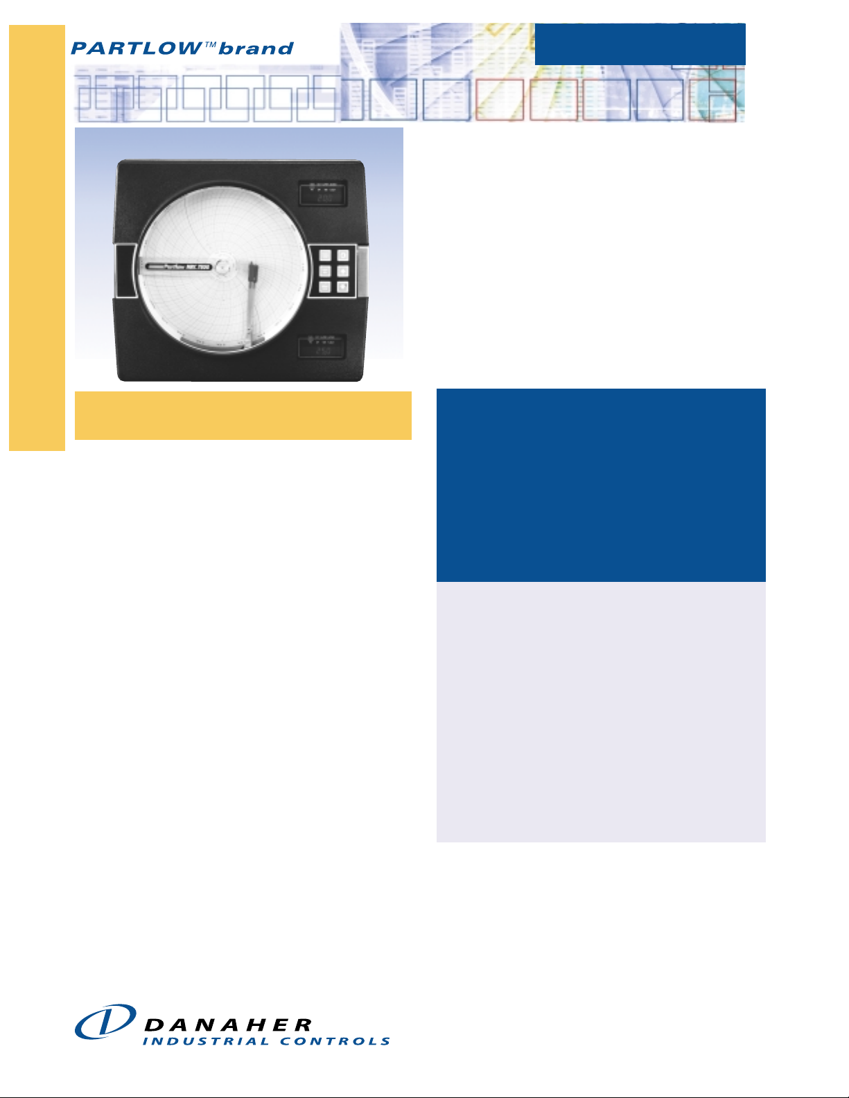
DESCRIPTION
The MRC 7800 Flow Controller is a microprocessor
based circular chart recorder capable of measuring,
displaying, recording and totaling flow process
variables. Record functions, alarm settings and other
parameters are easily configured from the front
mounted keypad and self-prompting displays.
All user data can be protected from unauthorized
changes by the Enable Mode security system. The
MRC7800 is protected against loss of data from AC
power failures by a standard battery backup system.
Applications for the MRC 7800 include process
validation, trend analysis, regulatory compliance and
product safety. Flow tracking is available with the
MRC 7800
™
Proven Recording Reliability
Designed Specifically for Flow
Applications!
APPLICATIONS:
• Process Validation, Trend Analysis, Regulatory
Compliance, Product Safety
• Flow/Rate Tracking with optional totalizing capability
INDUSTRIES
Harsh water environments, sewage treatment, effluent
flow, water treatment, etc.
FEATURES/BENEFITS
• Micro-based recording controller
• Two displays, allowing you to see critical process
values at the same time
• Easy, straightforward programming—allows you to
configure your recorder with a logical step-by-step
process using a simple keypad
• High reliability—eliminates cost of process
downtime
• Up to 8 relay or solid state outputs for use as
totalizer presets
• Up to 4 analog outputs for process retransmission
optional totalizing capability.
www.partlow.com • www.danaherindustrialcontrols.com
Process Automation Worldwide Brands: LFETM • PartlowTM • PMATM • RustrakTM • West
Customer Service +1 800.390.6405
Technical Support +1 800.866.6659
TM
Page 2
Recorders
Hollowshaft, Incremental EncodersFlow Controller
SPECIFICATIONS
STANDARD FEATURES
Modes: Digital; choice of Record or Diverse
Record/Totalizer combination functions.
Display: One 4-digit display (std.); second
display optional; 0.56˝ high, red, seven
segment LED; 3 button keypad; automatic and
decimal point positioning; Decimal Positions:
None, one, two or three decimal places.
Status Indicators: 7 LED status indicators: Out 1,
2; one green LED pen 2 indicator; LED
indicators ALRM1 and ALRM2.
Chart: 10˝ circular chart; 100 charts furnished
with each instrument. Unless otherwise
specified, charts shipped with instrument are
0–100 range. 24 hour rotation default setting.
Chart Drive: DC Stepper Motor.
Chart Rotation: User configurable from 0.1 and
999.9 hours per revolution.
Chart Range: Bottom and top of span –9999 to
9999 units.
Pen Type: One or two disposable fiber tip pen.
Pen Color: Pen 1 (red); Pen 2 (green).
Memory Backup: Battery; 5 year minimum life.
Construction/Enclosure: Injection molded Noryl
case; acrylic window cover.
OPERATING CHARACTERISTICS
Operating Temp: 32° to 122°F (0° to 50°C).
Storage Temp: –40° to 149°F (–40° to 65°C).
Humidity: 0% to 90% non-condensing R.H.
Vibration: 0.5 to 100Hz @ 0.2g.
Electro Static Discharge: No effect from 5000V
static charge over the entire area.
ELECTRICAL
Power Consumption: 25VA max.
Line Voltage: 115V or 230VAC ±10%, 50–60Hz.
MRC 7800
Proven Recording Reliability
Designed Specifically for Flow
Applications!
OUTPUTS
Relay: SPST/SPDT; 115VAC 5.0A Resistive,
1/8HP, 250VA; 230VAC 2.5A Resistive, 1/8HP,
250VA.
SSR Driver: Open collector output; short
circuit protected @ 100mA max; provides
4VDC @ 20mA or 3VDC @ 40mA.
Current: 0–20mA or 4–20mA; 0–650 ohm
maximum load.
Process Alarm: Direct (High) or Reverse (Low);
0 to 9999 units.
Deviation Alarm: N/A.
Deviation Band Alarm: N/A.
Alarm Hysteresis: 0–300 units (width of
hysteresis band).
PERFORMANCE
GENERAL:
Input Measurement Error: mA, mV, and VDC
±0.25% of scaled span or better typically;
±1 least significant digit @ 25°C.
Ambient Temperature Error: 0.01% of span per
degree C deviation from 25°C.
Isolation: N/A.
Chart Accuracy: ±1% of chart span.
Noise Rejection: Common Mode: 90dB
minimum; 24VAC maximum for RTD input;
115VAC max for other inputs. Normal Mode:
85dB minimum @ 60Hz or greater.
Transmitter Power Supply: Provides up to
42mA of current at 24 VDC.
COMMUNICATIONS INTERFACES
Communications Port: N/A
Protocol: N/A
Bit Rate: N/A
Address: N/A
™
PHYSICAL DIMENSIONS
Width: 15.13˝ (384mm).
Depth: 3.63˝ (92mm).
Height: 13.19˝ (335mm).
Weight: 20 lbs (9.1kg).
Mounting/Mounting Position: Panel or wall.
OPTIONS/ACCESSORIES
24V DC power supply option.
115 or 230VAC input option.
Door lock and sealed conduit/connector option.
NEMA 3 protection optional.
Totalizing flow option.
WARRANTY
3 years.
INPUTS
Thermocouple: N/A.
RTD: N/A.
Volts: 0–5 VDC*; 1–5 VDC*.
DC Milliamps: 4–20mA , 0–20mADC.
DC Millivolts*: 0–100mV (can be scaled to any
portion of this range).
* Accompanied by removal of a shunt resistor
factory installed on the input terminals.
RATINGS/AGENCY APPROVALS
Safety: UL 1092 File E67237; CSA Spec C22.2
File LR39885, CE EN61010-1 1993/1995.
Immunity: CE EN50082-1:1992
Emissions: CE EN55011:1991
Limit Device: N/A
Other: ISO 9002 registered.
PROTECTION
NEMA 3 optional
www.partlow.com • www.danaherindustrialcontrols.com
Process Automation Worldwide Brands: LFETM • PartlowTM • PMATM • RustrakTM • West
Customer Service +1 800.390.6405
Technical Support +1 800.866.6659
TM
Page 3

Flow
7 Two Pen
w/ Totalization
2 Two SPST
4 Four SPST
2 Two
4 Four
2 Two
Standard
/Isolated
Recorder
6 One Pen Rec.
1 One SPST
1 One
1 One
Standard
1 24VDC
Regulated
1 Data Logged
in Memory**
* Total quantity of SPST Relays and SSR Drivers must be less than or equal to eight.
When SPDT Relays are included, the total must be less than or equal to six.
**Available only on units with totalization.
*** This option comes with a structural foam cover.
8 Two Pen Rec.
9 One Pen
Recorder
w/ Totalization
Recorder with
Totalization
and second
display
6 Six SPST
7 One SPDT
8 Two SPDT
9 Two SPDT
and
Two SPST
6 Six
8 Eight
3 Three
4 Four
Standard
Standard
Shunt Resistor, P/N 64411702
Resistor, P/N 64411701 (provided with the unit) or the 10-50mA input and a 2.5 ohm
NOTE: 4-20mA inputs are accommodated using the 1-5V input and a 250 ohm Shunt
†N3 - NEMA type protection for wet environments.
MRC7800
5 One Pen
Recorder
0 None
0 None
0 None
0 None
0 None
78
Code 1:
Model
Code 2:
Pen & Totalization
Selrction
Code 3:
Relay (SPST)
Outputs*
Code 4:
SSR Driver
Outputs*
Code 5:
4-20mA
Outputs
Code 6:
Transmitter
Power Supply
Code 7:
Data Logging
Options
MODELS
Flow Controller
7 4 & 6
Combined
***
6 Sealed
Conduit
Connections
4 115VAC
5 115/230VAC
4 Door Lock
***
2 Standard
Cover
Windows)
(Plastic
1 115VAC
2 115/230VAC
CSA APPROVED
BLANK - None
N3 NEMA †
Required
0
Zeros
0
MRC 7800
Proven Recording Reliability
Designed Specifically for Flow
Applications!
Code 8:
Enclosure
Options
Code 9:
Operating
Voltage
™
Code 10:
Option
Suffix
Recorders
Page 4

Recorders
Hollowshaft, Incremental EncodersFlow Controller
DIMENSIONS
EC1
15.1"
(384.2 mm)
WIDTH OF COVER
MRC 7800
™
Proven Recording Reliability
Designed Specifically for Flow
Applications!
2.5"
(63.5 mm)
(65.9 mm)
2.6"
9
DIA.(7.1mm)
32
12.6"
(320.7 mm) (190.5 mm)
7.5"
13.9"
13.5"
( 354 mm)
(342.5 mm)
Made in USA.
* Specifications subject to change without notice in accordance with
Panel cut-out for flush mounting
Headquarters: 1675 Delany Road • Gurnee, IL 60031-1282 • USA
Phone: +1 847.662.2666 • Fax: +1 847.662.6633
Satellite Locations:
North America: North Carolina, South Carolina, Connecticut, Massachusetts, New York,
Canada, British Virgin Islands • Europe: United Kingdom, Italy, France, Germany, Spain,
Slovakia • Latin America: Brazil • Asia: China, Japan, Korea, Singapore
www.partlow.com • www.danaherindustrialcontrols.com
Process Automation Worldwide Brands: LFETM • PartlowTM • PMATM • RustrakTM • West
our DBS policy of continuous improvement. All product and brand
names are trademarks of their respective companies. All rights
reserved.
Partlow™ brand and MRC 7800™ are trademarks of Danaher Industrial
Controls Group. All rights reserved.
© 2005 DICG Corp.
Partlow Brand MRC 7800 Data Sheet (5/05)
Customer Service:
Tel.: +1.800.390.6405
Fax: +1.910.879.5486
partlow.custserv@dancon.com
TM
Technical Support:
Tel.: +1.800.866.6659
Fax: +1.847.782.5277
partlow.techsupport@dancon.com
 Loading...