

Page 1

MIC 1820 /1420
1/8 & 1/4 DIN MICROBASED CONTROLLERS
WITH FUZZY RaPID™ CONTROL
OPERATORS
MANUAL
FORM 3703
EDITION 1
© APRIL 1996
PRICE $10.00
Brand
Page 2

Information in this installation, wiring, and operation manual is subject to change
without notice. One manual is provided with each instrument at the time of shipment. Extra copies are available at the price published on the front cover.
Copyright © April 1996, The Partlow Corporation, all rights reserved. No part of
this publication may be reproduced, transmitted, transcribed or stored in a retrieval
system, or translated into any language in any form by any means without the
written permission of the Partlow Corporation.
This is the First Edition of the MIC 1820/1420 manual. It was written and produced entirely on a desk-top-publishing system. Disk versions are available by
written request to the Partlow Publications Department.
We are glad you decided to open this manual. It is written so that you can take full
advantage of the features of your new MIC 1820/1420 process controller.
NOTE:
It is strongly recommended that Partlow equipped
applications incorporate a high or low limit protective device
which will shut down the equipment at a preset process
condition in order to preclude possible damage to property
or products.
MIC 1820/MIC 1420 Manual Edition 12
Page 3

Table of Contents
Section 1 - General Page
1.1 Product Description 5
Section 2 - Installation & Wiring
2.1 Installation & Wiring 7
2.2 Preparations for Wiring 9
2.3 Input Connections 16
2.4 Output Connections 20
Section 3 - Configuration & Operation
3.1 Operation 24
3.2 Configuration 31
3.3 Pre-Tune Mode 39
3.4 Auto-T une Mode 39
3.5 RaPID Feature 42
3.6 Manual T uning Method 42
Section 4 - Control Capability
4.1 Control Capability 44
4.2 Control Responses 44
4.3 Direct/Reverse Operation of Control Outputs 45
4.4 On-Off Control 45
4.5 Time Proportioning Control 46
4.6 Current Proportioning Control 47
4.7 Setpoint Adjustments 48
Appendices
A - Glossary of Terms 49
Figure A-1 Alarm Actuation 55
Figure A-2 Alarm Hysteresis 57
Figure A-3 Asymmetrical Band Alarm 60
Figure A-4 Proportional Band & Deadband/Overlap 62
B - Board Layout - Jumper positioning 63
Figure B-1 PCB Positions (MIC 1820) 63
Figure B-2 PCB Positions (MIC 1420) 64
Figure B-3 Output 2/Output 3 Removal (MIC 1820) 65
Figure B-4 Output 2/Output 3 Removal (MIC 1420) 66
MIC 1820/MIC 1420 ManualEdition 1 3
Page 4

Appendices cont.
Figure B-5 CPU PWA 67
Figure B-6 PSU PWA with Relay or SSR Out.1 68
Figure B-7 PSU PWA with DC Output 1 69
Figure B-8 Option PWA 70
Figure B-9 CPU PW A with Remote Input Type 71
C - Hardware Definition Code 72
D - Input Range Codes/Remote Setpoint Input Codes 75
E - RaPID Control Feature/Alarm Hysteresis 77
F - Specifications 80
G - Model Number Hardware Matrix 89
H - Software Reference Sheet 90
Figures & Tables
Figure 1-1 Controller Display Illustration 6
Figure 2-1 Panel Cut-Out Dimensions 7
Figure 2-2 Main Dimensions 8
Figure 2-3 Panel Mounting the controller 9
Figure 2-4 Noise Suppression 12
Figure 2-5 Noise Suppression 12
Figure 2-6A 1/4 Din Wiring Label 14
Figure 2-6B 1/8 Din Wiring Label 15
Figure 2-7 AC Power 16
Figure 2-7A Nominal AC/DC Supply 17
Figure 2-8 Thermocouple Input 17
Figure 2-9 RTD Input 18
Figure 2-10 Volt, mV mADC Input 18
Figure 2-11 Remote Digital Connections 19
Figure 2-12 Remote Setpoint Input - V/mA/mV and Potentiometer 19
Figure 2-13 Remote Setpoint Selection 19
Figure 2-14 Dual Setpoint Selection 20
Figure 2-15 Relay Output 1 20
Figure 2-16 SSR Driver Output 1 20
Figure 2-17 mADC Output 1 21
Figure 2-18 Relay Output 2 21
Figure 2-19 SSR Driver Output 2 21
Figure 2-20 mADC Output 2 22
Figure 2-21 Relay Output 3 22
Figure 2-22 SSR Driver Output 3 22
Figure 2-23 mADC Output 3 23
Figure 4-1 Proportional Bandwidth Effect on Output 47
Table 3-1 Enable Mode Configuration Procedures 32
Table 3-2 Program Mode Configuration Procedures 32
Table 3-3 Tune Mode Configuration Procedures 35
MIC 1820/MIC 1420 Manual Edition 14
Page 5

Product Description 1.1
1.1.1 GENERAL
This instrument is a microprocessor based single loop controller capable of
measuring, displaying and controlling temperature, pressure, flow, and level
from a variety of inputs. Most outputs are easily tuned using the instrument
Pre-Tune and Auto-Tune, or RaPID (Response assisted PID) functions.
Control functions, alarm settings and other parameters are easily entered
through the front keypad. E
data loss during AC power outages.
The input is user configurable to directly connect to either thermocouple,
RTD, mVDC, VDC or mADC inputs. The instrument can operate from either
a 90-264 VAC, 50/60 HZ power supply, or optional 24V AC/DC power supply.
1.1.2 DISPLAYS
Each instrument is provided with dual displays and status indicators as
shown in Figure 1-1. The upper display (RED) displays the value of the
process variable. The lower display (GREEN) displays the setpoint value.
Status indication is as shown, see Figure 1-1, page 6.
2
Technology (100 year life) protects against
1.1.3 CONTROL
The instrument can be programmed for on-off, time proportioning, or current proportioning control implementations depending on the model number. A second control output is an available option. Proportional control
implementations are provided with fully programmable PID parameters.
1.1.4 ALARMS
Alarm indication is standard on all instruments. Up to two alarm outputs
are possible. Alarm type may be set as Process Direct or Reverse (high or
low), Deviation Direct or Reverse (above or below setpoint), Deviation
Band Type (closed or open within band), or Loop Reverse or Direct. Alarm
status is indicated by LED. An Alarm Inhibit is provided to prevent, when
activated, unwanted alarms during power-up.
MIC 1820/MIC 1420 ManualEdition 1 5
Page 6
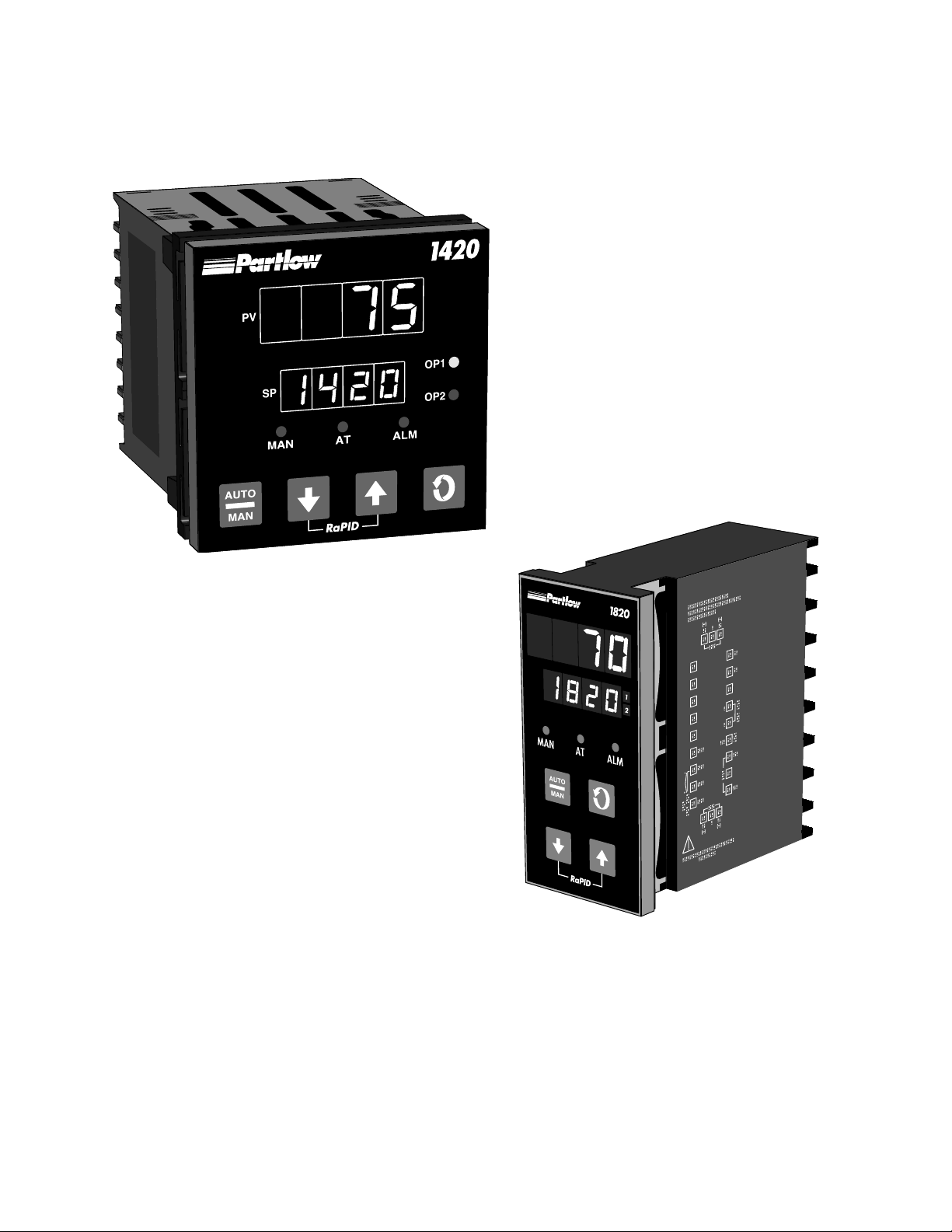
FIGURE 1-1
Keys and Indicators
1.1.5 PROCESS VARIABLE/SETPOINT VALUE
RE-TRANSMISSION OUTPUT
If the instrument is specified with this option, this output may be scaled over
any desired range and re-transmitted.
MIC 1820/MIC 1420 Manual Edition 16
Page 7
Installation and Wiring 2.1
Electrical code requirements and safety standards should be observed and
installation performed by qualified personnel.
The electronic components of the instrument may be removed from the
housing during installation. To remove the components, grip the side
edges of the front panel and pull the instrument forward. During re-installation, the vertically mounted circuit boards should be properly aligned in the
housing.
Ensure that the instrument is correctly orientated. A stop will operate if an
attempt is made to insert the instrument incorrectly.
Recommended panel opening sizes are illustrated in Figure 2-1. After the
opening is properly cut, insert the instrument into the panel opening. Ensure that the panel gasket is not distorted and that the instrument is positioned squarely against the panel. Slide the mounting clamp into place on
the instrument (see Figure 2-3, page 8) and push it forward until it is firmly
in contact with the rear face of the mounting panel.
Note: The mounting clamp tongues may engage either on the
sides or the top/bottom of the instrument housing. Therefore, when
installing several instruments side-by-side in one cut out, use the
ratchets on the top/bottom faces.
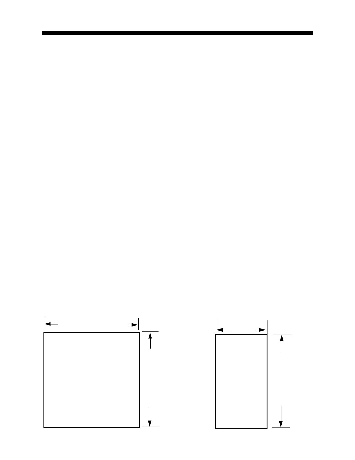
FIGURE 2-1
Panel Cut-Out Dimensions
92 mm +0.5 - 0.00
(3.62”+.020 - .000)
PANEL
CUTOUT
SIZE
92 mm + 0.5 - 0.0
(3.62” + .020 - .000)
45 mm +0.5 - 0.0
(1.77" +.020 - .000)
PANEL
CUTOUT
SIZE
92 mm +0.05 - 0.0
(3.62”+.020 -.000
MIC 1820/MIC 1420 ManualEdition 1 7
Page 8
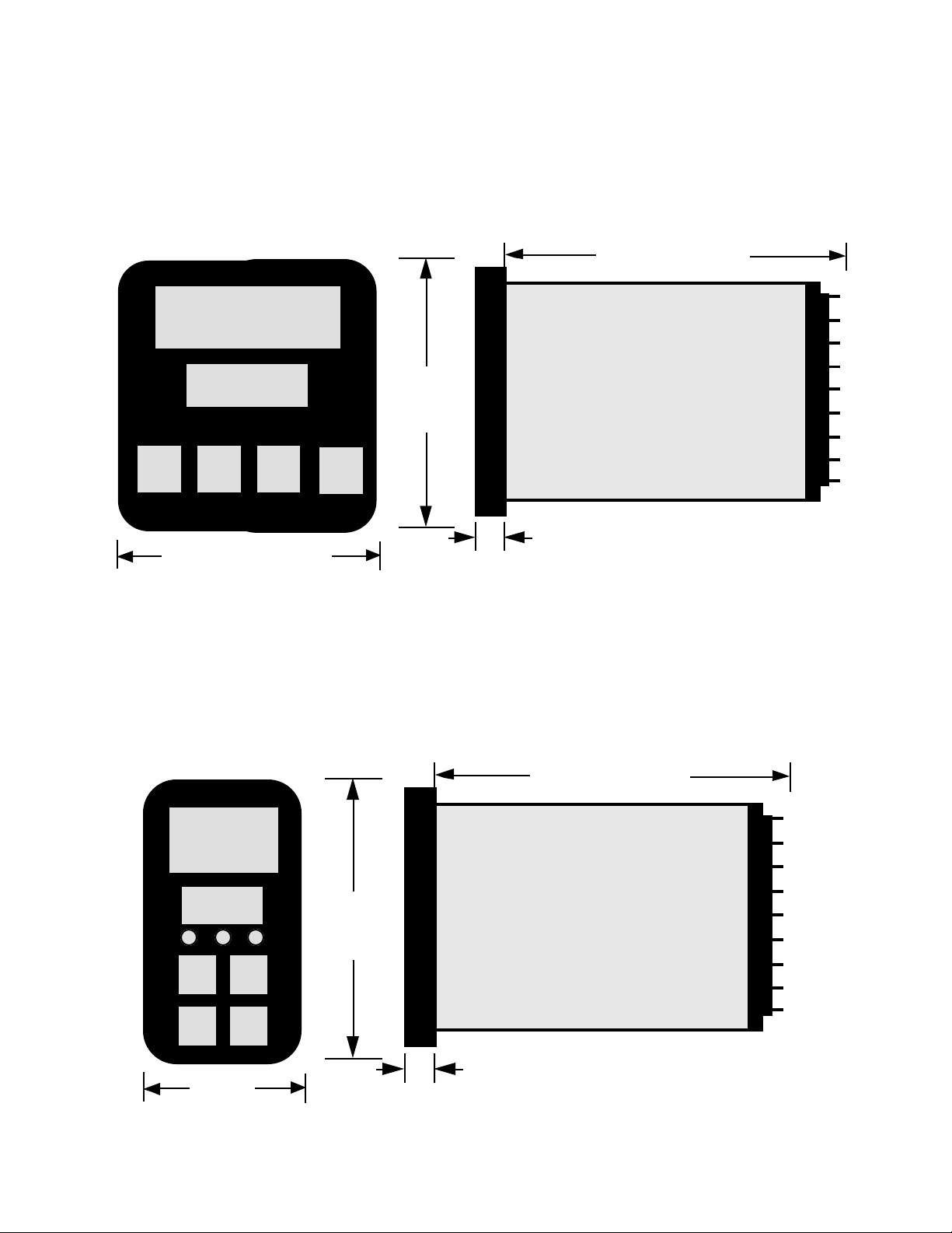
FIGURE 2-2
Main Dimensions
MIC 1420
100 mm (3.94 in.)
96 mm
(3.78 in)
Side View
MIC 1820
96 mm
(3.78 in.)
10 mm (0.39 in.)
Max. Panel thickness 6.0mm (.25 in)
100 mm (3.94 in.)
96 mm
(3.78 in)
48 mm
(1.89 in.)
MIC 1820/MIC 1420 Manual Edition 18
10 mm (0.39 in.)
Max. Panel Thickness 6.0mm (.25 in)
Side View
Page 9
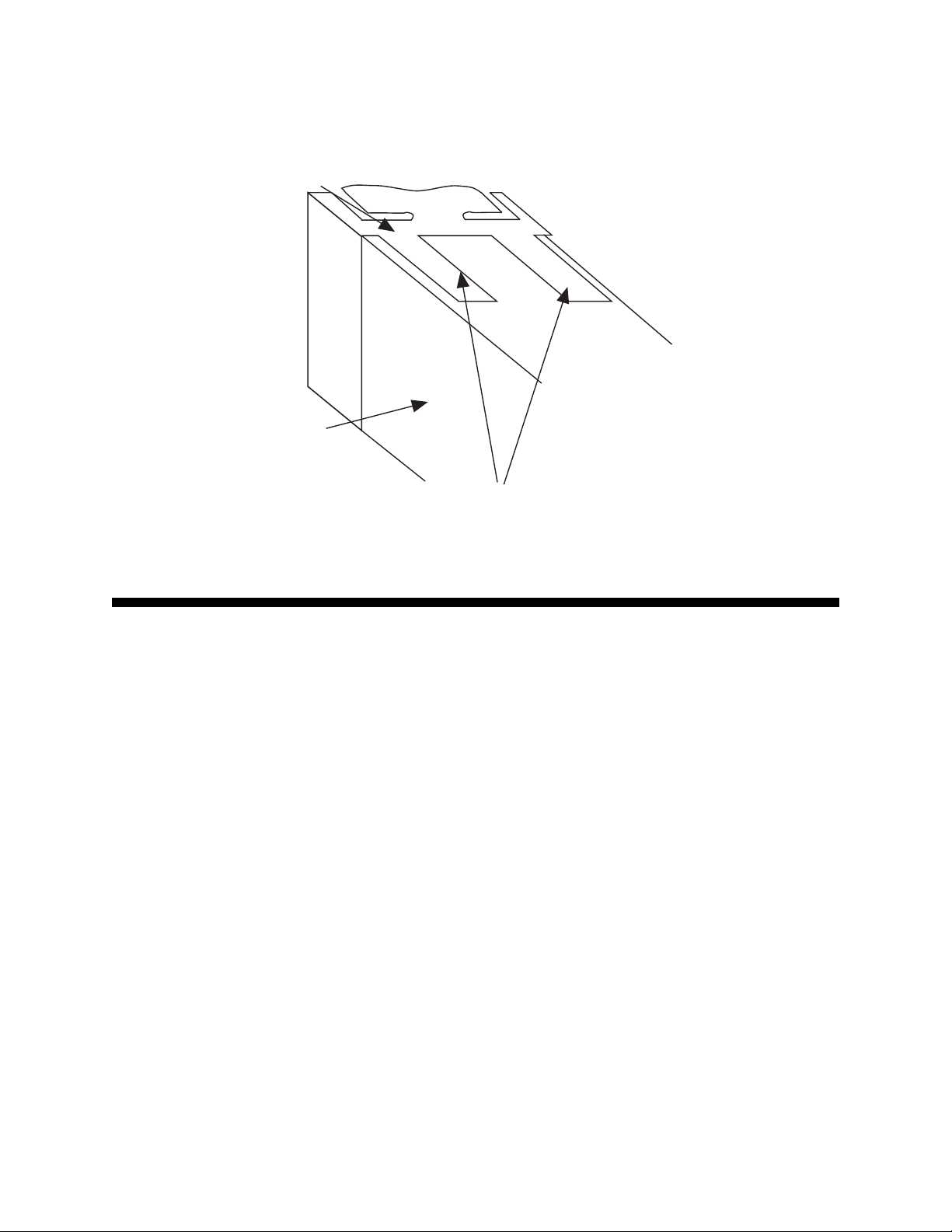
FIGURE 2-3
Panel Mounting the Controller
Mounting Clamp
Controller Housing
Tongues on mounting clamp engage in
ratchet slots on controller housing
Preparation for Wiring 2.2
2.2.1 WIRING GUIDELINES
Electrical noise is a phenomenon typical of industrial environments. The
following are guidelines that must be followed to minimize the effect of
noise upon any instrumentation.
2.2.1.1 INSTALLATION CONSIDERATIONS
Listed below are some of the common sources of electrical noise in the
industrial environment:
• Ignition Transformers
• Arc Welders
• Mechanical contact relay(s)
• Solenoids
Before using any instrument near the device listed, the instructions below
should be followed:
MIC 1820/MIC 1420 ManualEdition 1 9
Page 10

1. If the instrument is to be mounted in the same panel as any of the
listed devices, separate them by the largest distance possible. For
maximum electrical noise reduction, the noise generating devices
should be mounted in a separate enclosure.
2. If possible, eliminate mechanical contact relay(s) and replace with
solid state relays. If a mechanical relay being powered by an
instrument output device cannot be replaced, a solid state relay can
be used to isolate the instrument.
3. A separate isolation transformer to feed only instrumentation should
be considered. The transformer can isolate the instrument from noise
found on the AC power input.
4. If the instrument is being installed on existing equipment, the wiring in
the area should be checked to insure that good wiring practices have
been followed.
2.2.1.2 AC POWER WIRING
Neutral (For 115 VAC)
It is good practice to assure that the AC neutral is at or near ground potential. To verify this, a voltmeter check between neutral and ground should be
done. On the AC range, the reading should not be more than 50 millivolts.
If it is greater than this amount, the secondary of this AC transformer supplying the instrument should be checked by an electrician. A proper neutral
will help ensure maximum performance from the instrument.
2.2.1.3 WIRE ISOLATION
Four voltage levels of input and output wiring may be used with the unit:
• Analog input or output (i.e. thermocouple, RTD, VDC, mVDC, or mADC)
• SPDT Relays
• SSR driver outputs
• AC power
The only wires that should run together are those of the same category. If
they need to be run parallel with any of the other lines, maintain a minimum
6 inch space between the wires. If wires must cross each other, do so at
90 degrees. This will minimize the contact with each other and reduces
“cross talk”. “Cross Talk” is due to the EMF (Electro Magnetic Flux) emitted
by a wire as current passes through it. This EMF can be picked up by
other wires running in the same bundle or conduit.
MIC 1820/MIC 1420 Manual Edition 110
Page 11

In applications where a High Voltage Transformer is used (i.e. ignition systems) the secondary of the transformer should be isolated from all other
cables.
This instrument has been designed to operate in noisy environments, however, in some cases even with proper wiring it may be necessary to suppress the noise at its source.
2.2.1.4 USE OF SHIELDED CABLE
Shielded cable helps eliminate electrical noise being induced on the wires.
All analog signals should be run with shielded cable. Connection lead
length should be kept as short as possible, keeping the wires protected by
the shielding. The shield should be grounded at one end only. The preferred grounding location is the sensor, transmitter or transducer.
2.2.1.5 NOISE SUPPRESSION AT THE SOURCE
Usually when good wiring practices are followed no further noise protection
is necessary. Sometimes in severe electrical environments, the amount of
noise is so great that it has to be suppressed at the source. Many manufacturers of relays, contactors, etc. supply “surge suppressors” which
mount on the noise source.
For those devices that do not have surge suppressors supplied, RC (resistance-capacitance) networks and/or MOV (metal oxide varistors) may be
added.
Inductive Coils - MOV’s are recommended for transient suppression in
inductive coils connected in parallel and as close as possible to the coil.
See Figure 2-4. Additional protection may be provided by adding an RC
network across the MOV.
MIC 1820/MIC 1420 ManualEdition 1 11
Page 12
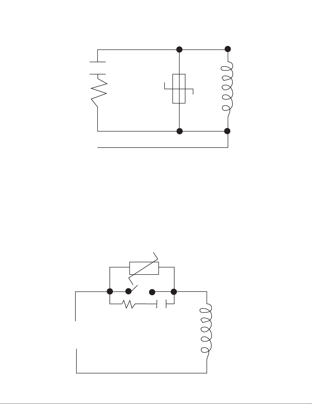
FIGURE 2-4
0.5
mfd
1000V
220
Coil
ohms
115V 1/4W
230V 1W
Contacts - Arcing may occur across contacts when the contact opens and
closes. This results in electrical noise as well as damage to the contacts.
Connecting a RC network properly sized can eliminate this arc.
For circuits up to 3 amps, a combination of a 47 ohm resistor and 0.1
microfarad capacitor (1000 volts) is recommended. For circuits from 3 to 5
amps, connect 2 of these in parallel. See Figure 2-5, below.
FIGURE 2-5
MOV
R C
MIC 1820/MIC 1420 Manual Edition 112
Inductive
Coil
Page 13

2.2.2 SENSOR PLACEMENT (Thermocouple or RTD)
Two wire RTD’s should be used only with lead lengths less than 10 feet.
If the temperature probe is to be subjected to corrosive or abrasive condi-
tions, it should be protected by the appropriate thermowell. The probe
should be positioned to reflect true process temperature:
In liquid media - the most agitated area
In air - the best circulated area
MIC 1820/MIC 1420 ManualEdition 1 13
Page 14
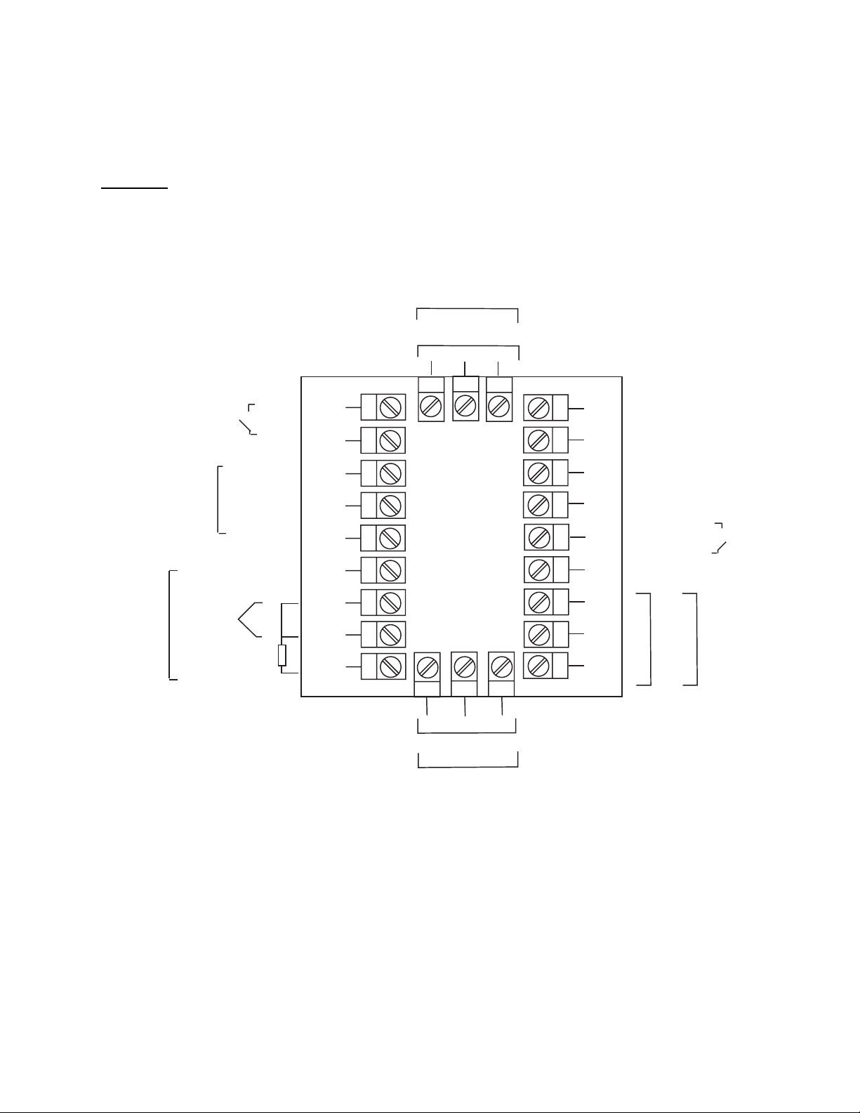
FIGURE 2-6
U
E
E
Wiring Label
1/4 DIN
REMOTE
SETPOINT
SELECTION
REMOTE
SETPOINT
INPUT
+
-
+
-
COM
V/mA/mV
Pot
-
OUTPUT 3
Relay
11
N/OC
+
1210
13
L
N/C
SSR/DC
-
9
+
8
7
6
5
4
3
14
15
16
17
18
19
N
MAINS (LINE)
B
A
RS485
COM
N/C
-
24V 24V
AC DC
SUPPLY
.
+
-
SERIAL
COMMS
D
S
S
+
Linear (mA)
UNIVERSAL
INPUT
-
Linear (V/mV)
+
RTD
Thermocouple
2
1
23 22
24
+
SSR/DC
N/O
Relay
OUTPUT 2
-
C
N/C
20
21
+
C
SSR/DC
N/O
Relay
OUTPUT 1
MIC 1820/MIC 1420 Manual Edition 114
Page 15
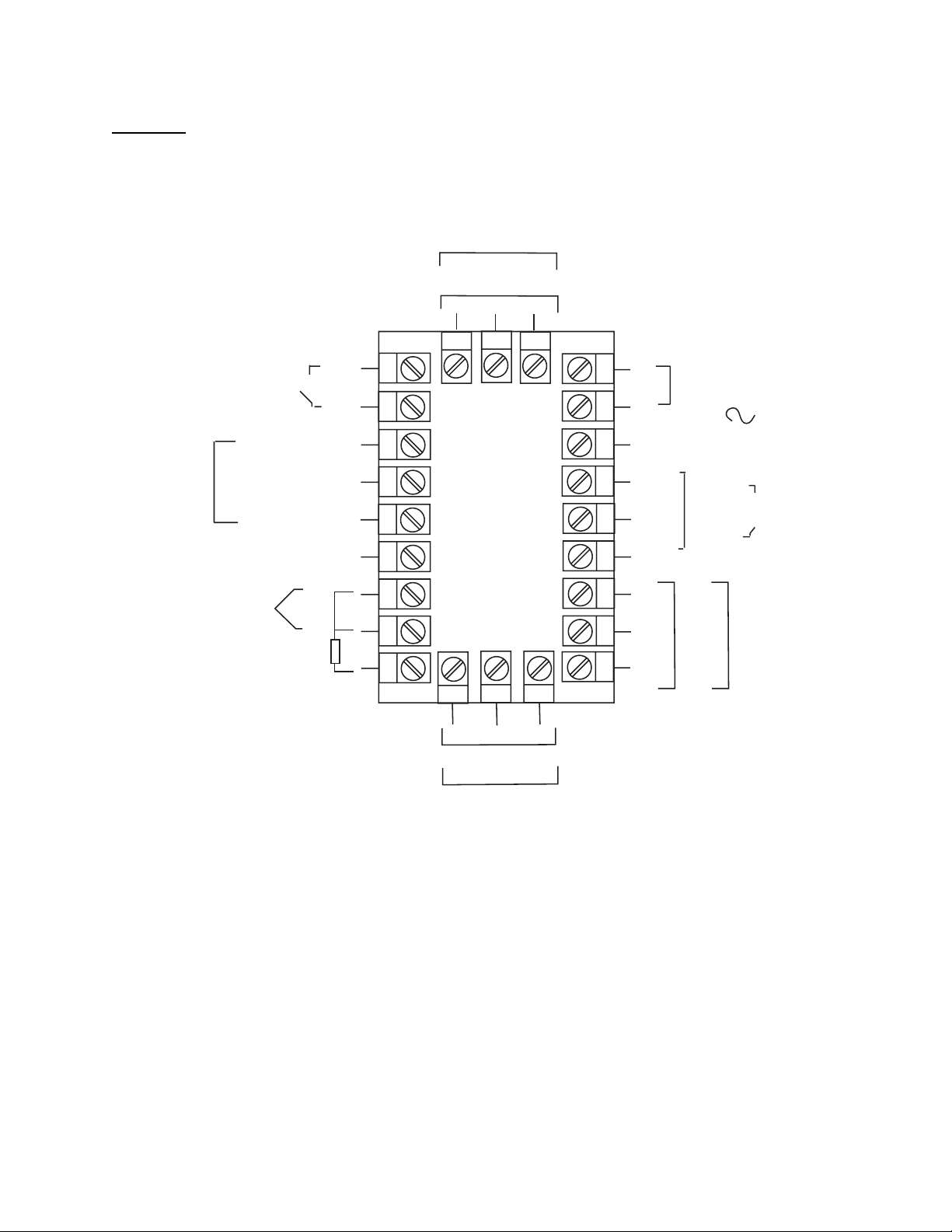
1/8 DIN
REMOTE
SETPOINT
SELECTION
REMOTE
SETPOINT
INPUT
+
+
COM
V/mA/mV
(Wiper)
Potentiometer
OUTPUT 3
Relay
11
N/OC
+
1210
L
13
N
14
MAINS
(LINE)
15
16
17
18
B
A
COM
SUPPLY
RS485
COMMS.
24 AC
+
DUAL
SETPOINT
SELECTION
-
SUPPLY
+ l
24V DC
SUPPLY
N/C
SSR/DC
-
9
-
8
7
6
5
4
-
UNIVERSAL
INPUT
Linear
(mA)
Linear
(V/mV)
+
-
+
T/C
RTD
3
2
1
23 22
24
N/O
C
Relay
+
SSR/DC
OUTPUT 2
N/C
-
19
20
21
N/C
C
N/O
-
Relay
+
SSR/DC
OUTPUT 1
MIC 1820/MIC 1420 ManualEdition 1 15
Page 16
Input Connections 2.3
In general, all wiring connections are made to the instrument after it is
installed. Avoid Electrical Shock. AC power wiring must not be connected
to the source distribution panel until all wiring connection procedures are
completed.
Caution: This equipment is designed for installation in an enclosure
which provide adequate protection against electric shock. Local
regulations regarding electrical installation should be rigidly observed. Consideration should be given to prevention of access to the
power terminations by unauthorized authorized personnel. Power
should be connected via a two pole isolating switch (preferably situated neat the equipment) and a 1 A fuse, as shown in Figure 2-7.
FIGURE 2-7
Main Supply
The instrument will operate on 90-264V AC 50/60 Hz mains (line) supply.
The power consumption is approximately 4 VA. If the instrument has relay
outputs in which the contacts are to carry mains (line) voltage, it is recommended that the relay contact mains (line) supply should be switched and
fused in a similar manner but should be separate from the instrument
mains (line) supply .
L
13
N
14
MIC 1820/MIC 1420 Manual Edition 116
Line
Neutral
Page 17
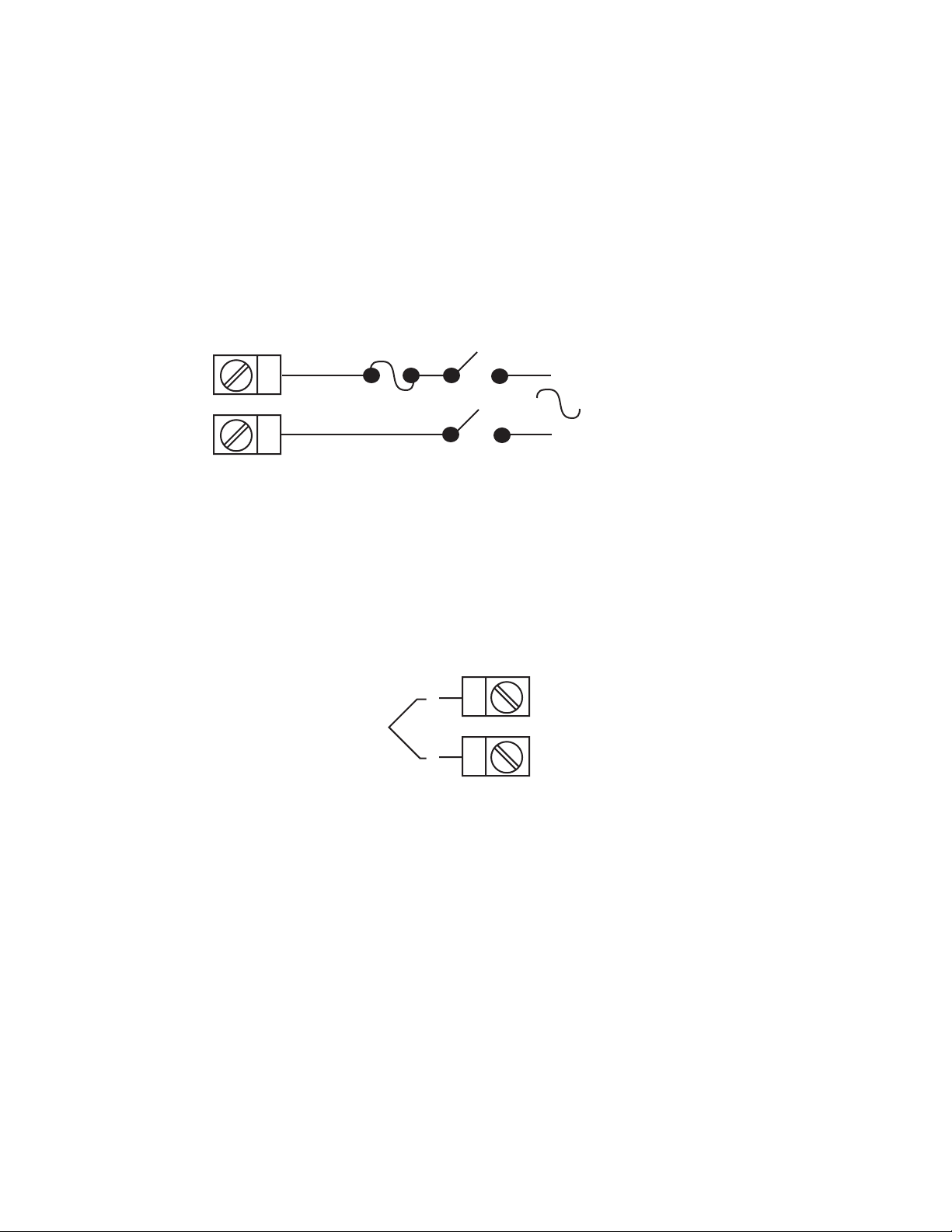
FIGURE 2-7A
24V Nominal AC/DC Supply
The supply connection for the 24V AC/DC option of the instrument are as
shown below . Power should be connected via a two pole isolating switch
and a 315 mA slow-blow (anti-surge type T) fuse. With the 24V AC/DC
supply option fitted, these terminals will accept the following supply voltage
ranges:
24V (nominal) AC 50/60Hz - 20-50V
24V (nominal) DC - 22-65V
L
13
24V AC
N
14
FIGURE 2-8
Thermocouple (T/C) Input
Make thermocouple connections as illustrated below. Connect the positive
leg of the thermocouple to terminal 2 and the negative leg to terminal 3.
50/60Hz
-
24V DC
+
-
+
Thermocouple
3
2
MIC 1820/MIC 1420 ManualEdition 1 17
Page 18

FIGURE 2-9
RTD Input
Make RTD connections as illustrated below . For a three wire RTD, connect
the resistive leg of RTD to terminal 1 and the common legs to terminals 2
and 3. For a two wire RTD, connect one leg to terminal 2 and the other leg
to terminal 3 as shown below. A jumper wire supplied by the customer
must be installed between terminals 2 and 3. Input conditioning jumper
must be positioned correctly (see Appendix B) and Hardware Definition
Code must be correct (See Appendix C).
3
2
RTD
1
FIGURE 2-10
V olt, mV Input
Make volt and millivolt connections as shown below . Terminal 2 is positive
and terminal 3 is negative. Input conditioning jumper must be positioned
correctly (see Appendix B) and Hardware Definition Code must be correct
(see Appendix C).
mADC Input
Make mADC connections as shown below. Terminal 4 is positive and terminal 1 is negative. Input conditioning jumper must be positioned correctly
(see Appendix B) and Hardware Definition Code must be correct (see Appendix C).
+
-
+
Linear (mA)
-
Linear (V/mV)
4
3
2
1
MIC 1820/MIC 1420 Manual Edition 118
Page 19
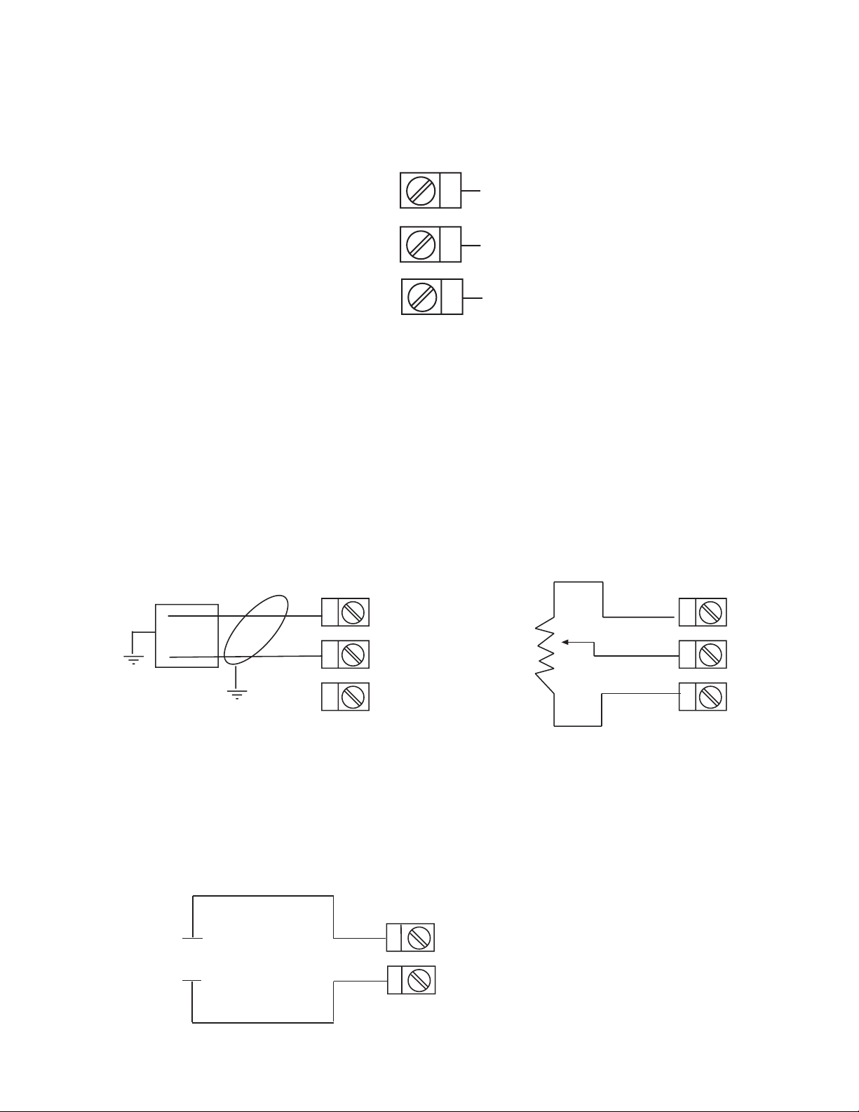
FIGURE 2-11
Remote Digital Communications - RS485
Make digital communication connections as illustrated below .
16
17
18
B
A
COM
FIGURE 2-12
Remote Setpoint Input - V/mA/mV and Potentiometer
Connections are illustrated below. Terminal 6 is positive and terminal 7 is
negative. The remote setpoint input can be configured for linear DC mv,
linear DC mA, linear DC Volt or potentiometer. Make sure that the input
selected matches the Second Input Usage selected in the Hardware Definition Mode and the Secondary Analog Input conditioning jumper is posi-
tioned correctly (see Appendix B.)
_
_
7
6
+
mA/mV
VOLT
+
5
FIGURE 2-13
Remote Setpoint Selection
Connections are made as shown.
+
DRY
CONTACT
7
6
5
Potentiometer
2 Kohms max
9
CONTACTS OPEN - LOCAL SETPOINT
8
-
CONTACTS CLOSED - REMOTE SETPOINT
MIC 1820/MIC 1420 ManualEdition 1 19
Page 20
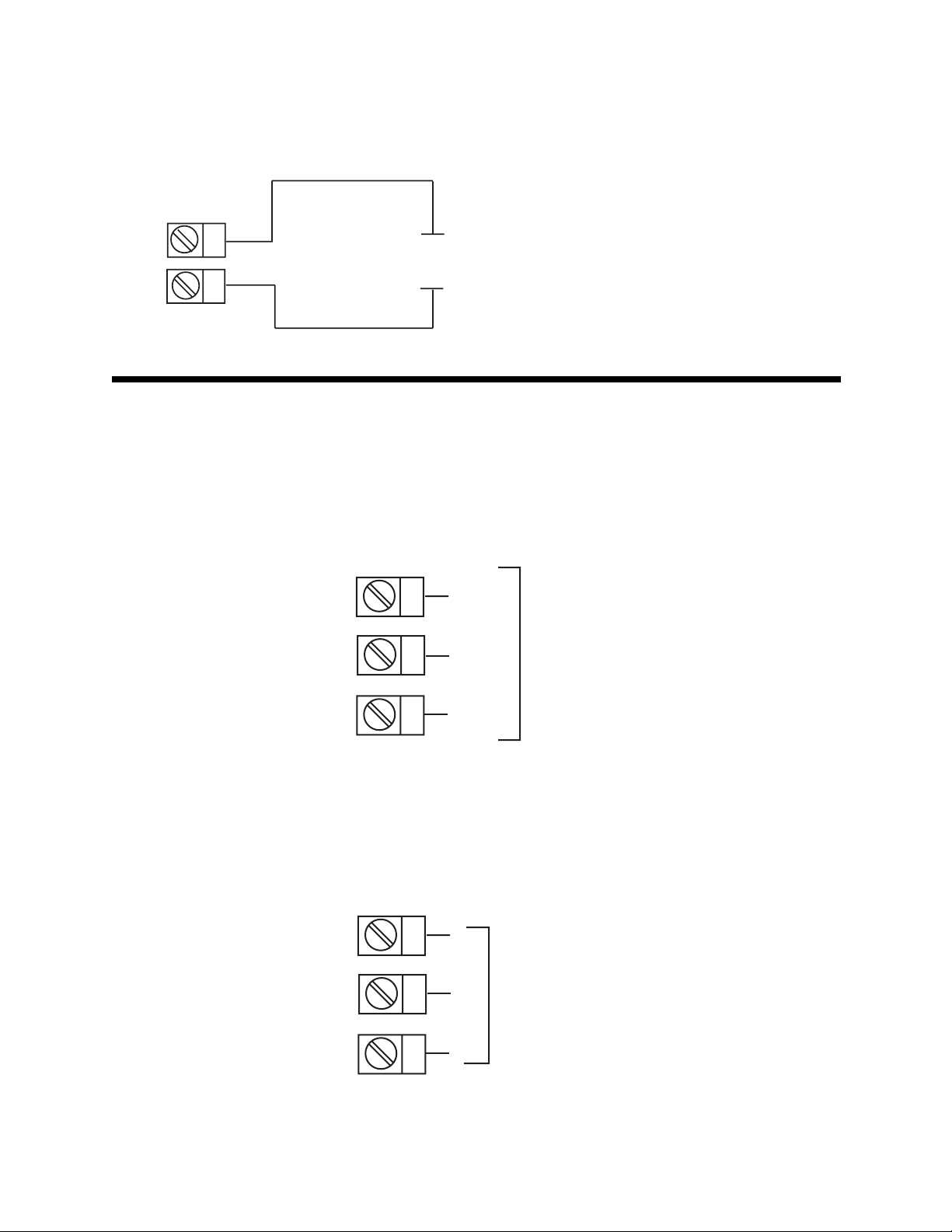
FIGURE 2-14
Dual Setpoint Selection
CONTACTS OPEN - SETPOINT 1
CONTACTS CLOSED - SETPOINT 2
16
17
DRY
CONTACT
Output Connections 2.4
FIGURE 2-15
Relay Output 1 (Control Output 1)
Connections are made to Output 1 relay as illustrated below. The contacts
are rated at 2 amp resistive, 120/240 V AC.
19
20
N/C
C
Relay
21
N/O
FIGURE 2-16
SSR Driver Output 1 (Control Output 1)
Connections are made to Output 1 SSR Driver as illustrated below. The
solid state relay driver is a non-isolated 0-4 VDC nominal signal. Output
impedance is 250 ohms.
19
-
20
SSR
21
+
MIC 1820/MIC 1420 Manual Edition 120
Page 21
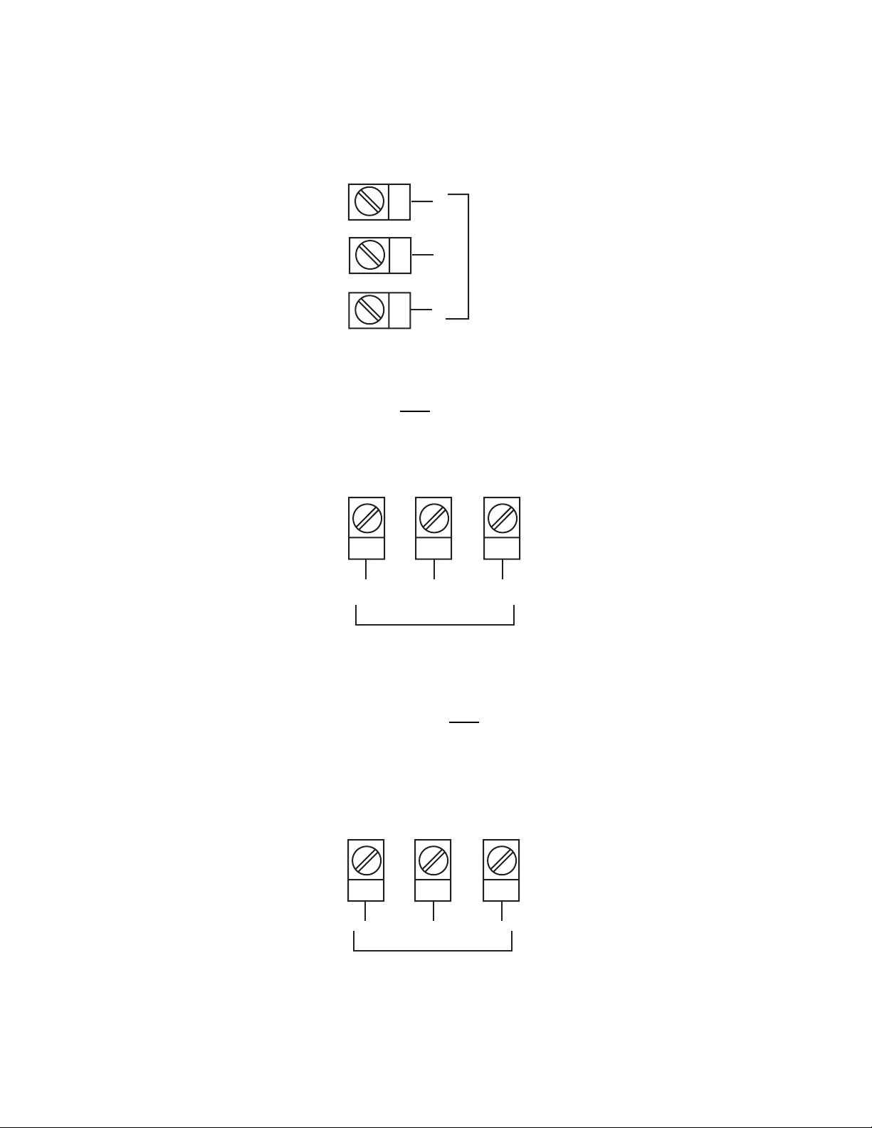
FIGURE 2-17
mADC Output 1 (Control Output 1)
Make connections for DC Output 1 as illustrated below.
C
-
DC
+
N/C
19
20
21
FIGURE 2-18
Relay Output 2 (Control Output 2
Connections are made to Output 2 relay as illustrated below. The contacts
are rated at 2 amp resistive, 120/240 V AC.
24 23 22
OR Alarm 2)
N/O
Relay
FIGURE 2-19
SSR Driver Output 2 (Control Output 2
Connections are made to Output 2 SSR Driver as illustrated below. The
solid state relay driver is a non-isolated 0-4 VDC nominal signal. Output
impedance is 250 ohms.
24 23 22
+
OR Alarm 2)
-
SSR
MIC 1820/MIC 1420 ManualEdition 1 21
Page 22
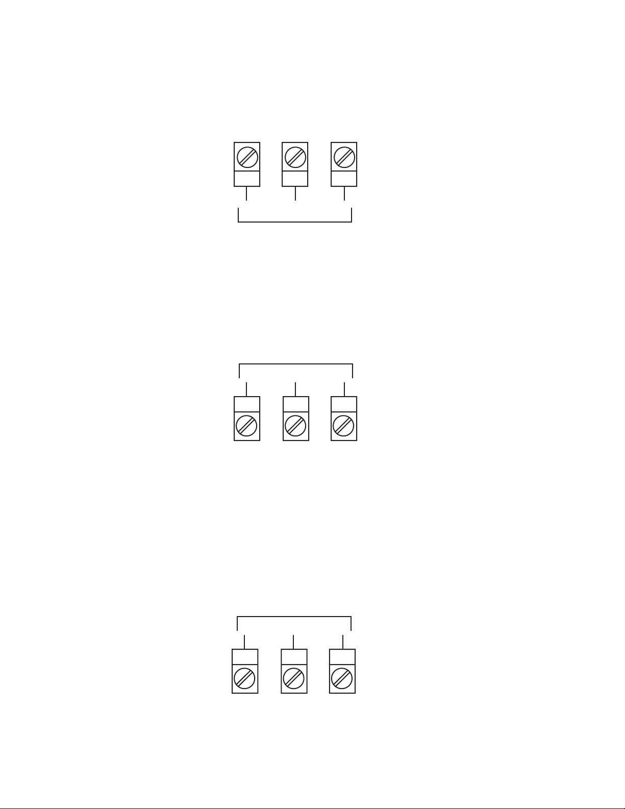
FIGURE 2-20
mADC Output 2 (Control Output 2)
Make connections for DC Output 2 as illustrated below.
24 23 22
+
DC
FIGURE 2-21
Relay Output 3 (Alarm 1)
Connections are made to Output 3 relay as illustrated below. The contacts
are rated at 2 amp resistive, 120/240 V AC.
Relay
10 11 12
FIGURE 2-22
SSR Driver Output 3 (Alarm 1)
Connections are made to Output 3 SSR Driver as illustrated below. The
solid state relay driver is a non-isolated 0-4 VDC nominal signal. Output
impedance is 250 ohms.
-
N/OCN/C
SSR
-
10 11 12
MIC 1820/MIC 1420 Manual Edition 122
+
Page 23
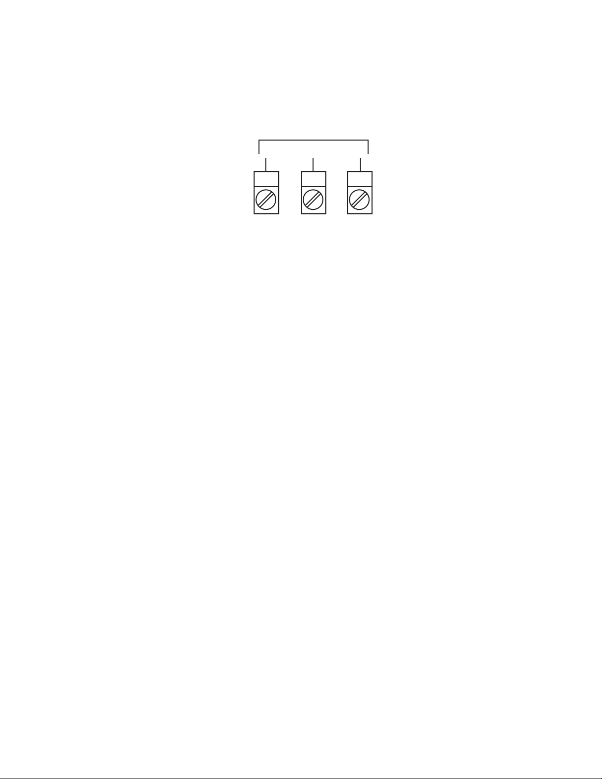
FIGURE 2-23
mADC Output 3 (Recorder Output Only)
Make connections for DC output 3 as illustrated below.
DC
-
10 11 12
+
MIC 1820/MIC 1420 ManualEdition 1 23
Page 24

Operation 3.1
3.1.1 POWER UP PROCEDURE
Verify all electrical connections have been properly made before applying
power to the instrument.
If the instrument is being powered for the first time, it may be desirable to
disconnect the controller output connections. The instrument will be into
control following the power up sequence and the output(s) may turn ON.
During power up, a self-test procedure is initiated during which all LED
segments in the two front panel displays appear and all LED indicators are
ON. When the self-test procedure is complete, the instrument reverts to
normal operation.
Note: A delay of about 3 seconds, when power is first applied, will be
seen before the displays light up.
3.1.2 KEYPAD OPERATION
AUTO/MANUAL KEY
This key is used to:
1. Enter the Auto/Manual mode and vice versa.
2. Used to activate the Auto Tune mode.
3. Used to confirm a change in the Program mode.
SCROLL KEY
This key is used to:
1. Select adjustment of the ramping setpoint, if enabled.
2. Select a parameter to be viewed or adjusted.
3. Display enabled modes of operation.
4. Display a mode parameter value.
5. Advance display from a parameter value to the next parameter code.
6. Activate the Pre-tune mode.
7. With the DOWN key to view the current Hardware Definition Code
setting.
MIC 1820/MIC 1420 Manual Edition 124
Page 25

UP KEY
This key is used to:
1. Increase the displayed parameter value.
2. Increase setpoint.
3. With the DOWN key to enter Pre and Auto Tune mode, and to engage
the RaPID function.
DOWN KEY
This key is used to:
1. Decrease the displayed parameter value.
2. Decrease setpoint.
3. With the UP key to enter the Pre and Auto Tune mode, and to engage
the RaPID function.
4. With the SCROLL key to view the current Hardware Definition Code
setting.
3.1.3 INITIAL DISPLAYS
After the instrument has performed its power up self test (during which, if
the SCROLL key is held down during power up, the current instrument
firmware revision is displayed), the initial Operator Mode displays appear.
These are dependent upon whether the instrument is configured for single
setpoint operation, dual setpoint operation or remote/local setpoint operation.
3.1.3.1 SINGLE SETPOINT OPERATION
Normally the initial displays are:
Upper Display = Process V ariable value
Lower Display = Setpoint value adjustable
The setpoint may be adjusted by using the UP/DOWN keys.
Press the SCROLL key again, if setpoint ramping is not disabled and if the
ramp rate is not switched OFF, to change the displays to:
Upper Display - Ramping Setpoint value ("Read Only")
Lower Display = the legend SPrP
MIC 1820/MIC 1420 ManualEdition 1 25
Page 26

3.1.3.2 DUAL SETPOINT OPERATION
If dual setpoint operation has been selected, the normal Operator Mode
displays will be as follows:
Upper Display = Process V ariable value
Lower Display = Active Setpoint value (adjustable)
Press the SCROLL key to change displays to :
Upper Display = Setpoint 1 value (adjustable)
Lower Display = the legend SP1
Press the SCROLL key again to obtain the equivalent display for Setpoint 2
(with legend SP2).
NOTE: The lower display uses the left-most character to distinguish between the active and inactive setpoints in the following manner:
SP2 SP2 SP2
Active Setpoint Active Setpoint Inactive Setpoint
(selected via (selected via
digital input) keypad override)
Press the SCROLL key again, if setpoint ramping is not disabled and if the
ramp rate is not switched OFF, to change the displays to:
3.1.3.3 REMOTE SETPOINT OPERATION
If remote setpoint operation has been selected the normal Operator Mode
displays will be as follows:
Upper Display = Process V ariable value
Lower Display = Active setpoint value (Adjustable)
Press the SCROLL key to change the displays to:
Upper Display = Ramping Setpoint value
Lower Display = the legend SPrP
Press the SCROLL key again to obtain the equivalent display for Remote
Setpoint (with the legend rSP).
NOTE: The lower display uses the left-most character to distinguish
between the active and inactive setpoints in the following manner:
SP SP rSP
MIC 1820/MIC 1420 Manual Edition 126
Page 27

3.1.3.4 OVERRIDE FEA TURE
While the instrument is being used with either Dual Setpoint operation or
Remote Setpoint operation, the Override feature is available. This enables
the active setpoint selected by the digital input to be manually overridden
from the keypad. To engage the Override feature, with the instrument displaying the desired setpoint (legend in lower display), press the UP and
DOWN keys simultaneously. This will cause the left-most character of the
lower display to show a flashing " ". This indicates that the display setpoint
is now the active setpoint, regardless of the state of the digital input.
To cancel an override condition, simply press the UP and DOWN keys
again with this display shown.
3.1.3.5 VIEWING/ADJUSTING THE SETPOINT RAMP RATE
If setpoint ramping is enabled, the ramp rate display may be selected using
the SCROLL key. The ramp rate may be adjusted (using the UP/DOWN
keys) within the range 1 to 999. Any attempt to increase the value beyond
999 will cause the upper display to go blank and setpoint ramping to be
switched OFF (default).
3.1.3.6 ALARM STATUS DISPLA Y*
The user may view the status of the instrument's alarm(s) by depressing
the SCROLL key until the lower display shows the legend "ALSt" and the
upper display shows the alarm status in the following format:
Loop Alarm Status
L = Energized
Blank = De-energized
Alarm 1 Status
1 = Energized
Blank = De-energized
Alarm 2 Status
2 = Energized
Blank = De-energized
*This display is available only if one or more of the alarms is/are energized.
When "ALSt" is seen in the lower display, to enter the Program or Tune
modes, press the UP key with "ALSt" displayed, then the SCROLL key to
Program or T une.
MIC 1820/MIC 1420 ManualEdition 1 27
Page 28

3.1.3.7 OVER-RANGE/UNDER-RANGE DISPLA Y
If the process variable attains a value higher than the input scale maximum
limit, the upper display will show:
If the process variable attains a value lower than the input scale minimum,
the upper display will show:
If a break is detected in the sensor circuit, the upper display will show:
3.1.4 FRONT PANEL INDICATORS
OP1 Indicates the state of the Output 1 relay or SSR driver. When the
indicator is ON the relay is energized or the SSR driver is ON.
OP2 Indicates the state of the Output 2 relay or SSR driver. When the
indicator is ON the relay is energized or the SSR driver is ON.
ALM When flashing, indicates an Alarm condition.
MAN Flashes when the Manual mode has been entered
AT Indicates when the Pre-Tune, Auto-Tune or RaPID mode has been
selected; flashing RED for Pre-T une, continuously ON RED for Auto-Tune
or flashing GREEN for RaPID activated.
MIC 1820/MIC 1420 Manual Edition 128
Page 29

3.1.5 SETPOINT ADJUSTMENT
3.1.5.1 LOCAL SETPOINT
To adjust the instrument setpoint, proceed as follows:
To adjust the Setpoint, press the UP or DOWN key as applicable.
Momentary depression will increment or decrement (as appropriate) the
setpoint by one unit in the least significant digit. If the key is held for longer
than 1 second, the least significant digit will change at the rate of 25 units
per second. If the key is held for longer than 10 seconds, the second least
significant digit will change at the rate of 25 units per second. If the key is
held for more than 10 seconds, the third least significant digit will change at
the rate of 25 units per second.
3.1.5.2 RAMPING SETPOINT
A selectable Ramp Rate function in the range of 1 to 9999 units per hour
can be used to limit the rate at which the setpoint used by the control algorithm will change. This feature will also establish a soft start up. Upon
power up, the instrument will take the initial process value as the setpoint.
A setpoint ramp rate will be calculated to increase the setpoint from the
initial process value to the setpoint selected. The setpoint ramp feature
disables the Pre-Tune facility. The Auto-Tune facility, if selected, will commence only after the setpoint has completed the ramp.
Sudden changes in the setpoint value entered via the keypad can be inhibited from effecting the control outputs by use of this feature. The internal
setpoint used to control the process will ramp to the setpoint value entered
at the rate of change selected.
To view the Ramping Setpoint value while in the Control mode and "ESPr"
in the Tune mode is disabled, press the SCROLL key until "SPrP" is displayed in the lower display. This is the code for the ramping setpoint value.
Press the SCROLL key one more time and the lower display shows "SPrP"
and the upper display will show the current ramping setpoint.
MIC 1820/MIC 1420 ManualEdition 1 29
Page 30

SPRr not OFF and ESPr equal to 0
PV BLANK Ramping SP PV
*SP SPrP SPrP *SP
If ESPr is enabled, the display sequence changes to:
PV BLANK Ramping SP BLANK *Ramp Rate PV
*SP SPrP SPrP SPrr SPrr *SP
*Adjustable
To enter the Program or Tune mode when setpoint ramping is selected,
press the SCROLL key until the lower display shows "SPrP" or "SPrr" and
the upper display is blank. With "SPrP" or "SPrr" display in the lower display , press the UP key once and "CtrL should be displayed in the lower
display. With "CtrL" displayed, press the SCROLL key until "Prog" or "tunE"
is displayed in the lower display .
Setpoint Ramp
205
204
Setpoint
in
Degrees
203
202
201
200
0
Time in Hours
5
10
3.1.6 MANUAL CONTROL
Manual Control is not applicable if the Auto/Manual selection in Tune mode
is disabled.
To enter the Manual mode, press the AUTO/MANUAL key. The Manual
mode status LED will begin to flash indicating that the Manual mode is in
use. Shifting from the Control to the Manual mode is bumpless. The proportional output(s) will stay at the last value(s) calculated by the control
MIC 1820/MIC 1420 Manual Edition 130
Page 31

algorithm. The upper display will show the current process value. The
lower display will show the current value output power in the form PXXX
where X is equal to the percentage of output power. The value of output
power may be adjusted using the UP and DOWN keys, as required.
The output power value can be varied in the range 0% of 100% for instruments using Output 1 only, and -100% to +100 % for instruments with both
Output 1 and Output 2.
To exit from the Manual mode, press the Auto/Manual key. Shifting to the
Control mode is bumpless.
Configuration 3.2
All configurable parameters are provided in Tables 3-1 through 3-3 on the
following pages. These tables illustrate the display sequence, parameter
adjustment and factory setting for each step.
Depression of the SCROLL key will cycle the display if Setpoint Ramp Rate
is not enabled (top display is blank, lower display shows the parameter
code) through all enabled modes as follows:
CONTROL ---- PROGRAM ---- TUNE
(Ctrl) (Prog) (tunE)
If a mode is not enabled it will be skipped over by the routine.
3.2.1 ENABLE MODE
The Enable mode provides a means of enabling or disabling access to the
Program and Tune modes. If a mode has been disabled, then that mode
will not be displayed or available to the user in the Control mode. See
Table 3-1 (page 29-30) for the Enable Mode procedure.
3.2.2 PROGRAM MODE
The Program mode is used to configure or re-configure the instrument.
The input and output selections are made in the Program mode. All possible parameters are illustrated in Table 3-2 (page 31). Only those parameters that are applicable to the hardware options chosen will be displayed.
MIC 1820/MIC 1420 ManualEdition 1 31
Page 32

3.2.3 TUNE MODE
The Tune mode is used to adjust the tuning parameters, alarm settings,
setpoint limits, and retransmit scaling needed for proper operation of the
instrument. See Table 3-3 (page 33) for Tune mode. Only those parameters that are applicable will be displayed.
TABLE 3-1 ENABLE MODE
To enter the Enable mode, press and hold the UP and DOWN keys. After 5
seconds (the AT LED should have flashed once), the display returns to
normal. After 5 more seconds, "EnAb" will be displayed. Release the keys,
the display should show "EPro". Pressing the DOWN key will display the
Enable mode codes in the following sequence:
EPro - - Etun - - ESPC
Pressing the SCROLL key will display the Enable mode codes with the
upper display blank. The next depression of the SCROLL key will add the
Enable code status (ON or OFF) to the upper display. With the Enable
code status displayed, use the UP key to change the status to ON and the
DOWN key to change the status to OFF.
To exit the Enable mode, press the UP key with the Enable code displayed
in the lower display and the upper display blank.
DISPLAY AVAILABLE FACTORY
STEP DESCRIPTION CODE SETTINGS SETTING
1 Program Mode EPro ON/OFF ON
2 Tune Mode Etun ON/OFF ON
3 Setpoint ESPC ON/OFF ON
Changes
TABLE 3-2 PROGRAM MODE
To enter the Program mode, press and release the SCROLL key until
"Prog" is displayed. Use the DOWN key to enter the Program mode. Depress and release the SCROLL key to sequence through the parameters
and their values, alternately showing the parameter code in the lower display with the upper display blank, then the parameter code with the parameter value displayed. Use the UP and DOWN keys to adjust the parameter
values. After adjusting a parameter, the upper display will flash, indicating
that the new setting has yet to be confirmed. When the setting is as re-
MIC 1820/MIC 1420 Manual Edition 132
Page 33

quired, it may be confirmed by pressing the AUTO/MANUAL key and the
upper display stops flashing. After confirming a change, press the
SCROLL key to proceed to the next parameter. Use the DOWN key to
advance to the next parameter when a parameter code is showing in the
lower display and the upper display is blank.
To exit the Program mode, press the UP key whenever a parameter code is
displayed in the lower display and the upper display is blank.
DEFAULT PARAMETER INDICATION
If a parameter value, such as Input Select, was changed while in the Program mode, when returning to the Control mode, a decimal point after each
digit will be lit. This display indicates all Tune mode parameters have been
set to their default condition. To clear this condition, enter the Tune mode
and make a parameter value change and review each parameter for its
proper setting.
DISPLAY AVAILABLE FACTORY
STEP DESCRIPTION CODE SETTINGS SETTING
1 Input Select inPS See App. D* 1420
2 ** Remote Setpoint rinP See App. D **
3 Output 1 Action Out1 Reverse REV
Direct
4 Alarm 1 Type ALA1 P_hi=Proc High P_hi
nonE=No Alarm
bAnd=Band
dE=Deviation
P_Lo=Proc Low
5 Alarm 2 Type ALA2 Same selection nonE
as ALA1
6 Alarm Inhibit Inhi nonE=No Inhibit P_hi
ALA1=Alarm1 Inhibited
ALA2=Alarm2 Inhibited
both=Both Inhibited
MIC 1820/MIC 1420 ManualEdition 1 33
Page 34

DISPLAY AVAILABLE FACTORY
STEP DESCRIPTION CODE SETTINGS SETTING
7 Output 2 Usage USE2 Out2=Control Out2
(opposite of Out1 action)
LP_r=Loop Reverse
LP_d=Loop Direct
Ad_r=Rev Logic AND
Ad_d=Dir Logic AND
Or_r=Rev Logic OR
Or_d=Dir Logic OR
A2_r=Alm 2 Rev
(Continued on the next page)
A2_d=Alm2 Dir
Hy_d=Alm Hyst Dir Act***
Hy_r=Alm Hyst Rev Act**
8 Output 3 Usage USE3 Al_d=Alm 1 Dir A1_d
rEcP=Rcdr Out P.V.
rEcS=Rcdt Out S.P.
LP_r=Loop Reverse
LP_d=Loop Direct
Ad_r=Rev Logic AND
Ad_d=Dir Logic AND
Or_r=Rev Logic OR
Or_d=Dir Logic OR
Al_r=Alm 2 Rev
Hy_d=Alm Hyst Dir Act***
Hy_r=Alm Hyst Rev Act***
9 Com Bit Rate CbS 1200, 2400, 4800, 9600 4800
10 Com Address CAd 1-32 1
11 CJC Enable CJC EnAb EnAb
disA
* The Hardware Definition Code and input jumper configuration may need
to be changes. See Appendix B and C.
** If Remote Setpoint Input has been selected in the Hardware Definition
MIC 1820/MIC 1420 Manual Edition 134
Page 35

Code, this parameter will appear in the normal Program Mode parameter
sequence. The upper display shows a product code which defines the
input range. The factory setting depends on code selected, see Appendix
D.
*** An Alarm Hysteresis output is made active only when both alarms become active; it subsequently becomes inactive only when both alarms are
inactive. Thus, the status of an Alarm Hysteresis output only when one
alarm is active depends upon the alarm status immediately prior to that
alarm being activated. See Appendix E.
TABLE 3-3 TUNE MODE
To enter the Tune mode, press and release the SCROLL key until tunE is
displayed. Use the DOWN key to enter the Tune mode. Depress and release the SCROLL key to sequence through the parameters and their values, alternately showing the parameter code in the lower display with the
upper display blank, then the parameter code with the parameter value
displayed. Use the UP and DOWN keys to adjust the parameter values.
After adjusting a parameter, depress the SCROLL key to proceed to the
next parameter. Use the DOWN key to advance to the next parameter
when a parameter code is showing in the lower display and the upper display is blank.
To exit the Tune mode, press the UP key whenever a parameter code is
displayed in the lower display and the upper display is blank.
1 Ramping SPrP ± Setpoint Limits Read Only
Setpoint V alue
2 Setpoint Ramp SPrr 1 to 9999 units/hour OFF
Rate and OFF
3* Input Filter Filt 0.0 to 100.0 2.0
seconds in .5 sec.
increments
4 Input Correct iCor ± Span 0
5 Output 1% Po1 0 to 100% Read Only
(Continued on next page)
MIC 1820/MIC 1420 ManualEdition 1 35
Page 36

DISPLAY AVAILABLE FACTORY
STEP DESCRIPTION CODE SETTINGS SETTING
6 Output 2% Po2 0 to 100% Read Only
7 1st Output Pb1 0 to 999.9% 5.0
Prop. Band of Input Span
0%=On/OFF
8 2nd Output Pb2 0 to 999.9% 5.0
Prop. Band of Input Span
0%=ON/OFF
9 Automatic ArSt OFF to 99 mins. OFF
Reset 59 secs/Repeat
10 Rate rAtE 0 sec to 99 mins. 0 secs.
59 secs.
11 Overlap/ SPrd -20 to 20% of 0%
Deadband Pb1 and Pb2
12 Manual Reset rSEt 0 to 100% Output 1 25%
-100 to 100% Out 2
13 Hysteresis
Output 1 HyS1 0.1 to 10.0% of span 0.5
Output 2 HyS2 0.1 to 10.0% of span 0.5
Out 1 & Out 2 HySt 0.1 to 10.0% of span 0.5
14 Setpoint SPuL Span Max. Span Max.
Upper Limit
15 Setpoint SPLL Span Min. Span Min.
Lower Limit
16 Remote rSPu -1999 to 9999 PV Range
Setpoint Maximum Maximum
17 Remote rSPL -1999 to 9999 PV Range
Setpoint Minimum Minimum
MIC 1820/MIC 1420 Manual Edition 136
Page 37

DISPLAY AVAILABLE FACTORY
STEP DESCRIPTION CODE SETTINGS SETTING
18 Remote rSPo -1999 to 9999 0
Setpoint Offset
19 Process Pou -1999 to 9999 Span Max.
Output Upper
20 Process PoL -1999 to 9999 Span. Min.
Output Lower
21 Output 1 o1PL 0 to 100% 100
% Limit
22 Output 1 Ct1 .5, 1, 2, 4, 8, 16, 32, 32
Cycle Time 64, 128, 256, 512
secs
23 Output 2 Ct2 .5, 1, 2, 4, 8, 16, 32, 32
Cycle Time 64, 128, 256, 512
secs
24 Process High PHA1 ± Span Span Max.
Alarm 1
25 Process Low PLA1 ± Span Span Min.
Alarm 1
26 Band Alarm 1 bAL1 0 to Span 5
27 Deviation dAL1 ± Span 5
Alarm 1
28 Alarm AHy1 1 LSD to 10% 1 LSD
Hysteresis of span
29 Process High PHA2 ± Span Span Max.
Alarm 2
MIC 1820/MIC 1420 ManualEdition 1 37
Page 38

DISPLAY AVAILABLE FACTORY
STEP DESCRIPTION CODE SETTINGS SETTING
30 Process Low PLA2 ± Span Span Min.
Alarm 2
31 Band Alarm 2 bAL2 0 to Span 5
32 Deviation dAL2 ± Span 5
Alarm 2
33 Alarm 2 AHy2 1 LSD to 10% 1 LSD
Hysteresis of span
34 Loop Alarm LAEn 0=Disable 0
Enable 1=Enable
35 Loop Alarm LAti 1 sec to 99 mins. 99 mins.
Time 59 secs. 59 secs.
36 Decimal dPoS 0, 1, 2, 3 1
Position (Linear Input Only)
37 Engineering Euu -1999 to 9999 1000
Units Upper
38 Engineering EuL -1999 to 9999 0
Units Lower
39 *Enable Pre EPtn 0=Disable 0
T u n e 1=Enable
40 Enable Manual ESby 0=Disable 0
Control 1=Enable
41 **Setpoint Ramp ESPr 0=Disable 0
Rate Enable 1=Enable
42 Comm. Enable CCon 0=Disable 1
1=Enable
MIC 1820/MIC 1420 Manual Edition 138
Page 39

* Activates Pre-Tune on power-up when enabled.
** When enabled, allows user to change ramp rate without having to enter
Tune mode.
NOTE: Pre-tune and Auto-TUne Modes will not function if OUTPUT 2 has
been configured ON/OFF.
Pre-Tune Mode 3.3
The Pre-Tune mode may be used to set the instrument's PID parameters to
values which are approximately correct, in order to provide a base from
which the Auto Tune mode may optimize tuning.
To engage the Pre-Tune mode, with the instrument in Control mode, press
and hold the UP and DOWN keys for approximately 5 seconds (the display
will flash during this period) until the AT LED flashes once. Release the UP
and DOWN keys. Press and hold the SCROLL key for approximately 3
seconds until the AT LED flashes.
To disengage the Pre-Tune mode, press and hold the UP and DOWN keys
until the AT LED flashes once. Release the UP and DOWN keys. Press
and hold the SCROLL key for approximately 3 seconds until the AT LED is
continuously OFF.
Note: Since the Pre-Tune mode is a single-shot operation, it will automatically disengage itself once the operation is complete. If the Enable Pre-Tune parameter in the Tune mode is enabled, then upon
power interruption, the unit will first engage the Pre-T une mode prior
to engaging the Auto-Tune mode when power is restored.
Also note: The Pre-Tune mode will not engage during setpoint ramping. Additionally, if the process variable is within 5% of input span
from the setpoint, or if an incorrect key sequence is used, the PreTune mode will not be engaged.
Auto-Tune Mode 3.4
The Auto-Tune mode is used to optimize tuning while the instrument is
operating.
MIC 1820/MIC 1420 ManualEdition 1 39
Page 40

To engage the Auto-Tune mode, with the instrument in Control mode, press
and hold the UP and DOWN keys for approximately 5 seconds (the display
will flash during this period) until the AT LED flashes once. Release the UP
and DOWN keys. Press and hold the AUTO/MAN key for approximately 3
seconds until the AT LED lights continuously.
Note: If the Enable Pre-Tune parameter in the Tune mode is enabled,
then on power-up, the unit will automatically engage the Pre-Tune
mode prior to engaging the Auto-Tune mode when power is restored.
To disengage the Auto-Tune mode, press and hold the UP and DOWN keys
until the AT LED flashes once. Release the UP and DOWN keys. Press
and hold the AUTO/MAN key for approximately 3 seconds until the AT LED
is continuously OFF.
How Auto-T une Works
This instrument uses a pattern recognition algorithm, which monitors the
process error (deviation signal). Figure 3-1 shows a typical temperature
application involving process start up, a setpoint change and a load disturbance. The deviance signal is shown shaded and overshoots have been
exaggerated for clarity .
The auto-tuning algorithm observes one complete deviation oscillation
before calculating a set of PID values. Successive deviation oscillations
cause values to be recalculated so that the controller rapidly coverages on
optimal control.
When auto-tuning controllers are switched off, the final PID terms remain
stored in the controller's nonvolatile memory, and are used as starting values at the next switch on.
The stored values are not always valid, if for instance, the controller is
brand new or the application has changed. In these cases the user can
utilize an extra facility on the auto-tuning controllers called "Pre-Tune". Figure 3-2 shows how the "Pre-T une" facility artificially disturbs the start up
pattern so that a first approximation of the PID values can be made prior to
the setpoint being reached.
MIC 1820/MIC 1420 Manual Edition 140
Page 41

New instruments supplied by the factory contain PID terms set at "DEFAULT" values which have been found to give adequate and safe control
over a wide range of applications. In the "Pre-Tune" mode of operation, the
"default" PID terms are loaded and the controller demands 100% power
until the process value has moved approximately halfway to the setpoint.
At that point, power is removed thereby introducing a deviation oscillation.
Once the oscillation peak has passed, the Pre-Tune algorithm can calculate
its first approximation to the optimum PID values. The power is reapplied
using new values. This technique limits possibility of setpoint overshoot
when the instrument is new or the application has been changed.
FIGURE 3-1
TEMPERATURE
SETPOINT 2
Load Disturbance
SETPOINT 1
FIGURE 3-2
TEMPERATURE
Setpoint Change
TIME
Setpoint
100% power for
this period
Pre-Tune complete here
new PID values loaded
and power re-applied
TIME
MIC 1820/MIC 1420 ManualEdition 1 41
Page 42

RaPID Feature 3.5
The RaPID (Response assisted PID) range of controllers have been designed with a unique "fuzzy" logic algorithm which dramatically reduces
overshoot and improves settling times on start-up, setpoint changes and
disturbances by 70%, without complicating set-up and usage.
The fuzzy logic based algorithm enhances the traditional PID function,
continuously reblending the P, I and D control building blocks on line. Instead of learning from an event and reacting after it has happened (which is
how all self-tuning PID controllers work, ) the RaPID controllers can react
as an event occurs, thereby improving the quality of control and speed of
response in any application.
To engage the RaPID feature, press the UP and DOWN keys simultaneously twice in quick succession. The same key action is used to disengage the RaPID feature.
To engage the RaPID feature and the Pre-Tune together, press the UP and
DOWN keys twice in quick succession , then immediately press SCROLL
key . The Pre-Tune feature than performs its single shot operation (A T LED
will flash green), after which the RaPID feature automatically starts to operate (A T LED will be ON green).
For a detailed description of the RaPID feature, refer to Appendix E.
NOTE: If either Pb1 to Pb2 is zero, the RaPID feature cannot be engaged.
Manual Tuning Method 3.6
1. Cycle Time - Time Proportioning Outputs
A. Adjusting the cycle time affects instrument operation
1. Shorter Cycle Time
a. More accurate control
b. Shorter life span of electromechanical
components
MIC 1820/MIC 1420 Manual Edition 142
Page 43

2. Proportional Bandwidth
A. Proportional Bandwidth is the inverse of gain.
Increased Bandwidth = Decreased Gain
B. Increase the Proportional Bandwidth if:
1. The process overshoots excessively
2. The process oscillates excessively
C. Decrease the Proportional Bandwidth if:
1. The process responds slowly
2. The process fails to reach setpoint
3. Add Automatic Reset
A. Increase the Automatic Reset (decrease the time) until the
process becomes unstable, then decrease (increase the
time) until stability is restored.
B. Be sure to allow sufficient time for the process and the
instrument to react.
4. Rate Adjustment
A. Rate can cause process instability. Typically add Rate as
1/10 th of the automatic reset value.
B. Decrease Rate if:
1. The process overshoots/undershoots
2. If the process oscillates excessively
5. Manual Reset
A. After making all other adjustments, use if an offset exists
between the setpoint and the process variable.
B. If the process is:
1. Below setpoint use a positive Manual Reset value
2. Above the setpoint use a negative Manual Reset value
MIC 1820/MIC 1420 ManualEdition 1 43
Page 44

Control Capability 4.1
A variety of user programmable control features and capabilities are available including:
• Auto Tune • Single On-Off Control
• Alarm Functions • Single Time Proportioning Control
• Auto/Manual Switching • Single Current Proportioning
• Process Retransmission • Dual On-Off Control
• Setpoint Retransmission • Dual Time Proportioning
• Setpoint Ramp Rate • Dual Current Proportioning
• Proportioning (Time or Current)/
On-Off Control
The capabilities available in a specific unit are dependent upon the hard-
ware options specified when the instrument is ordered. Refer to Appendix
F for the decoding of the instrument model number. Current proportioning
control cannot be implemented if a current output was not ordered. The
available output types and quantity of each are as follows:
Type of Output Quantity Available
• SPDT mechanical relay output Up to three
• SSR Driver Up to three
• mADC current output Up to two
Control Responses 4.2
Each instrument may be configured to provide 3 mode proportional control.
Proportional control is provided with Proportional Band, Integration, and
Derivative responses. The PID parameters are defined as follows:
Out 1 Out2
P (Proportional) Proportional Band Pb1 Pb2
I (Integration) Automatic Reset ArSt ArSt
D (Derivative) Rate rAtE rAtE
Manual Reset is provided for use in lieu of, or in conjunction with automatic
reset. A cycle time adjustment parameter is provided for use with each
time proportioning control output.
MIC 1820/MIC 1420 Manual
44
Edition 1
Page 45

Direct/Reverse Operation of Outputs 4.3
Direct operation is typically used with cooling applications. On-Off direct
output(s) will turn on when the process variable exceeds setpoint. Proportional direct output(s) will increase the percentage of output as the process
value increases within the proportional band.
Reverse operation is typically used with heating applications. On-Off reverse output(s) will turn off when the process variable exceeds setpoint.
Proportional reverse output(s) will decrease the percentage of output as the
process value increases within the proportional band.
Output 2 will be Direct when Output 1 is selected as Reverse and Reverse
when Output 1 is selected as Direct.
On-Off Control 4.4
On-Off control can be implemented with SPDT relay or SSR driver
output(s) by setting the corresponding proportional band (Pb) to 0.0. OnOff operation can be assigned to Output 1 only (Output 2 not present),
Output 1 AND Output 2, or Output 2 only (Output 1 is time proportional or
current proportional). A hysteresis adjustment is provided for On-Off outputs, "HyS1" for Output 1 only, "HySt" for Output 1 AND Output 2, or
"HyS2" for Output 2 only. This adjustment is in % of input span and defines
the bandwidth of the hysteresis. Relay chatter can be eliminated by proper
adjustment of this parameter . When operating in On-Off control, the
output(s) will turn on or off depending upon the setpoint, the process value,
and the hysteresis adjustment.
Edition 1
45
MIC 1820/MIC 1420 Manual
Page 46

Time Proportioning Control 4.5
Time Proportioning control can be implemented with a SPDT relay or SSR
driver. Time proportioning control can be selected for either Output 1 or
Output 1 and Output 2, depending on hardware configuration. Time proportioning control is accomplished by cycling the output on and off during a
prescribed period of time when the process variable is within the proportional band.
Ex: Calculated output % = 40%; Cycle time adjustment = 32 seconds
Output on time = .4 x 32 = 12.8 seconds
Output off time = .6 x 32 = 19.2 seconds
When the unit is operating in the Control mode, the control algorithm determines the output % required to correct for any difference between the process value and the setpoint. The output calculation is affected by Tune
mode parameter adjustments. See Figure 4-1 (page 37) for proportional
bandwidth effect on the output.
MIC 1820/MIC 1420 Manual
46
Edition 1
Page 47

Current Proportioning Control 4.6
Current Proportioning control can be implemented on units provided with
mADC current output(s). Current Proportioning control provides a 4 to
20mADC or 0-20mADC output in response to process value and setpoint.
As with Time proportioning, the calculated output % for Current proportioning is affected by the Tune mode parameter adjustments.
See Figure 4-1 (below) for proportional bandwidth effect on the output.
FIGURE 4-1
Proportional Band 1
Pb1
Output 1
Output 2
Setpoint
Output Power (%)
Proportional
Band 1
Pb1
Output 1
Output 2
Output Power (%)
Setpoint
Proportional
Band 1
Output 1
Pb1
Proportional Band 2
Pb2
Overlap
(Positive value)
SPrd
Deadband
(negative value)
SPrd
Proportional Band 2
Output 2
Output 1
Process Variable
Proportional
Band 2
Pb2
Output 2
Output 1
Process Variable
Pb2 = 0
Output 2
Edition 1
Output 2
Output Power (%)
Setpoint
Positive values Negative values
Overlap/Deadband
Output 2 OFF
Sprd
47
Output 2 ON
Output 1
Process Variable
ON/OFF
Differential
HyS2
MIC 1820/MIC 1420 Manual
Page 48

Setpoint Adjustment 4.7
To adjust the setpoint with the instrument in the Control mode, press the
UP key to raise the setpoint and the DOWN key to lower the setpoint.
Depressing the SCROLL key, if setpoint ramping is enabled and if ramp
rate is not OFF will change the displays to:
Upper Display = Ramping Setpoint Value (Read Only)
Lower Display = SPrP
MIC 1820/MIC 1420 Manual
48
Edition 1
Page 49

Appendix A
Glossary of Terms
Input Filter Time Constant
This parameter is used to filter out any extraneous impulses on the process
variable. This filtered PV is used for all PV-dependent functions (control,
alarm, etc). The time constant is adjustable from 0.0 seconds (of f) to 100.0
seconds, in 0.5 second increments. Default value is 2.0 seconds. Display
code is FiLt.
Input Correction
This parameter is used to modify the actual process variable and is adjustable in the range ± input span. Default value is 0. Display code is iCor.
Proportional Band 1
This parameter is the portion of the input span over which the Output 1
power level is proportional to the displayed process variable value. It may
be adjusted in the range 0.0% (ON/OFF) to 999.9%. Default value is 5.0%.
Display code is Pb1. The function is illustrated in Figure A-1, page 49.
Proportional Band 2
This parameter is the portion of the input span over which the Output 2
power level is proportional to the displayed process variable value. It may
be adjusted in the range 0.0% (ON/OFF) to 999.9%. Default value is
5.0%.* Display code is Pb2. In Figure A-1 (page 49), Proportional Band 2
is shown (a) with a nonzero value (Case 1 and Case 2) - PID Control, and
(b) with a zero value (Case 3) - ON-OFF control.
Automatic Reset (Integral)
This parameter is used to bias the proportional output(s) to compensate for
process load variations. It is adjustable in the range 1 second to 99 minutes 59 seconds per repeat and OFF (value greater than 99 minutes 59
seconds). Decreasing the time increases the Reset. This parameter is not
available if Pb1 is set to 0. Default value is OFF. Display code is ArSt.
*This parameter is applicable only if Output 2 is present.
Edition 1
49
MIC 1820/MIC 1420 Manual
Page 50

Rate (Derivative)
This parameter is adjustable in the range 00 seconds to 99 minutes 59
seconds and specifies how the control action responds to the rate of
change in the process variable. This parameter is not available if Pb1 is
set to 0. Default value is 0.0. Display code is rAtE.
Overlap/Deadband
This parameter defines the portion of the proportional band (Pb1 + Pb2)
over which both outputs are active (or, in the case of a deadband, neither
output is active ). It is adjustable in the range -20% to +20% (negative
value = deadband). The function is illustrated in Figure A-1, page 49. This
parameter is not applicable if Pb1 = 0 or if there is no Output 2. Default
value is 0%. Display code is SPrd.
Note: With Output 2 set on ON/OFF (Figure A-1, page 50, Case 3) the
Overlap/Deadband parameter has the effect of moving the ON hysteresis
band of Output 2 to create an overlap (positive values) or a deadband
(negative values). When Overlap/Deadband = 0, the Output 2 OFF edge of
the Output 2 ON/OFF hysteresis band coincides with the point at which
Output 1 = 0%.
Manual Reset
This parameter is expressed as a percentage of output power and is adjustable in the range 0% to 100% (if only Output 1) or -100% to +100% (if
both Output 1 and Output 2). This parameter is not applicable if Pb1 = 0.
Default value is 25%. Display code is rSEt.
Hysteresis
This parameter is a switching differential used when one or both outputs
have been set to ON/OFF. This parameter is adjustable within the range
0.1% to 10.0% of input span. Default value is 0.5%. Display code is HyS1,
HyS2, HySt. Note: Alarm output hysteresis is fixed at 2° C/F.
Setpoint Upper Limit
This parameter is the maximum limit for setpoint adjustment. It should be
set to a value which prevents the setpoint being given a value which will
cause damage to the process. The range of adjustment is to Maximum
Input Range. Default value is Range Maximum. Display code is SPuL.
MIC 1820/MIC 1420 Manual
50
Edition 1
Page 51

Setpoint Lower Limit
This parameter is the minimum limit for setpoint adjustment. It should be
set to a value which prevents the setpoint being given a value which will
cause damage to the process. The range of adjustment is to Minimum
Input Range. Default value is Range Minimum. Display code is SPLL.
Process Output Upper Value
This parameter defines the value of the retransmitted output (process variable or setpoint , whichever is applicable) at its maximum value; for example, for a 0-5V output, this value corresponds to 5V. It may be adjusted
within the range -1999 to 9999. The decimal position is always the same
as that for the process variable input. Default value is Input Range Maximum. Display code is Pou.
Note: If this parameter is set to a value less than that for the Process Output Lower Value, the relationship between the process variable/setpoint
value and the retransmission output is reversed.
Remote Setpoint Maximum
This, and the Remote Setpoint Minimum parameter define the scaling of
the RSP input (which is a linear input). This parameter may be adjusted
between -1999 and +9999, with the decimal point position as for the primary input. After scaling, the RSP value range is limited by the Setpoint
Upper and Lower Limits. Thus, if the scaled RSP value is greater than the
Setpoint Upper limit, the RSP value will be clamped to the Setpoint Upper
Limit. The default value is Input Range Maximum. Display code is rSPh.
Remote Setpoint Minimum
This, and the Remote Setpoint Maximum parameter define the scaling of
the RSP input (which is a linear input). This parameter may be adjusted
between -1999 and +9999, with the decimal point position as for the primary input. After scaling, the RSP value range is limited by the Setpoint
Upper and Lower Limits. Thus, if the scaled RSP value is less than the
Setpoint Lower Limit, the RSP value will be clamped to the Setpoint Lower
Limit. The default value is Input Range Minimum. Display code is rSPL.
Edition 1
51
MIC 1820/MIC 1420 Manual
Page 52

Remote Setpoint Offset
This parameter is used to modify the remote setpoint value in the following
manner:
Offset remote setpoint value = setpoint value + remote setpoint offset
value
Default value is 0. Display code is rSPo.
Process Output Lower V alue
This parameter defines the value of the retransmitted output (process variable or setpoint, whichever is applicable) at its minimum value; for example, for a 0-5V output, this value corresponds to 0 V. It may be adjusted
within the range -1999 to 9999. The decimal position is always the same
as that for the process variable input. Default value is Input Range Minimum. Display code is PoL.
Note: If this parameter is set to a value greater than that for the Process
Output Upper Value, the relationship between the process variable/setpoint
value and the retransmission output is reversed.
Output 1 Percent Limit
This parameter is used to limit the power level of Output 1 and may be
used to protect the process being controlled. It may be adjusted between 0
% and 100%. This parameter is not applicable if Pb1 = 0. Display code is
o1PL.
Cycle Time
This parameter is used to select the on/off cycle time for time proportioning
outputs (Ct1 for Output 1 and Ct2 for Output 2). The permitted range of
value is 0.5, 1, 2, 4, 8, 16, 32, 64, 128, 256, or 512 seconds. Default value
is 32. Display codes Ct1 & Ct2.
Process High Alarm 1 Value
This parameter, applicable only when Alarm 1 is selected to be a Process
High alarm, defines the process variable value at or above which Alarm 1
will be active. Its value may be adjusted between Input Range Maximum
and Input Range Minimum. Its default value is Input Range Maximum.
Display code is PHA1.
MIC 1820/MIC 1420 Manual
52
Edition 1
Page 53

Process Low Alarm 1 Value
This parameter, applicable only when Alarm 1 is selected to be a Process
Low alarm, defines the process variable value at or below which Alarm 1
will be active. Its value may be adjusted between Input Range Maximum
and Input Range Minimum. Its default value is Input Range Minimum. Display code is PLA1.
Band Alarm 1 Value
This parameter, applicable only if Alarm 1 is selected to be a Band Alarm,
defines a band of process variable values, centered on the setpoint value.
If the process variable value is outside this band, the alarm will be active.
This parameter may be adjusted from 0 to span from the setpoint. The
default value is 5. The display code is bAL1.
Deviation Alarm 1 Value
This parameter, applicable only if Alarm 1 is selected to be a Deviation
High/Low Alarm, defines a value above (positive value - Deviation High
Alarm) or below (negative value - Deviation Low Alarm) the setpoint; if the
process variable deviates from the setpoint by a margin greater than that
defined by this parameter, Alarm 1 goes active. This parameter may be
adjusted in the range ± span from setpoint. The default value is 5. Display
code is dAL1.
Alarm 1 Hysteresis
This parameter applies a hysteresis band on the "safe" side of the Alarm 1
value. Thus, Alarm 1 will become active when the Alarm 1 value is exceeded; Alarm 1 will become inactive when the process variable value is
outside the hysteresis band on the "safe" side of the Alarm 1 value. Alarm
1 Hysteresis may be set to a value in the range 1 (least significant digit) to
10% of input span (expressed as display units). The default value is 1.
Display code is AHy1. The effects of the hysteresis value on the operation
of the different types of alarms is illustrated in Figure A-2.
Process High Alarm 2 Value
This parameter, applicable only when Alarm 2 is selected to be a Process
High Alarm, defines the process variable value at or above which Alarm 2
will be active. Its value may be adjusted between Input Range Maximum
and Input Range Minimum. Its default value is Input Range Maximum.
Display code is PHA2.
Edition 1
53
MIC 1820/MIC 1420 Manual
Page 54

Process Low Alarm 2 Value
This parameter, applicable only when Alarm 2 is selected to be a Process
Low Alarm, defines the process variable value at or below which Alarm 2
will be active. Its value may be adjusted between Input Range Maximum
and Input Range Minimum. Its default value is Input Range Minimum.
Display code is PLA2.
Band Alarm 2 Value
This parameter, applicable only if Alarm 2 is selected to be a Band Alarm,
defines a band of process variable values, centered on the setpoint value.
If the process variable is outside this band, the alarm will be active. This
parameter may be adjusted from 0 to span from the setpoint. The default
value is 5. Display code is bAL2.
Deviation Alarm 2 Value
This parameter, applicable only if Alarm 2 is selected to be a Deviation
High/Low Alarm, defines a value above (positive value - Deviation High
Alarm) or below (negative value - Deviation Low Alarm) the setpoint; if the
process variable deviates from the setpoint by a margin greater than that
defined by this parameter, Alarm 2 goes active. This parameter may be
adjusted in the range ± span from setpoint. The default value is 5. Display
code is dAL2.
Alarm 2 Hysteresis
This parameter applies a hysteresis band on the "safe" side of the Alarm 2
value. Thus, Alarm 2 will become active when the Alarm 2 value is exceeded; Alarm 2 will become inactive when the process variable value is
outside the hysteresis band on the "safe" side of the Alarm 2 value. Alarm
2 Hysteresis may be set to a value in the range 1 (least significant digit) to
10% of input span (expressed as display units). The default value is 1.
Display code is AHy2. The effects of the hysteresis value on the operation
of the different types of alarms is illustrated in Figure A-2.
MIC 1820/MIC 1420 Manual
54
Edition 1
Page 55

FIGURE A-1
Alarm Actuation
Process High Alarm
direct-acting
Process High Alarm
reverse-acting
Process Low Alarm
direct-acting
Process Low Alarm
reverse-acting
"ALM" Off
Relay Off
"ALM" Off
Relay On
"ALM" flashes
Relay On
"ALM" flashes
Relay Off
"ALM" flashes
Relay On
PV
ALARM POINT
"ALM" flashes
Relay Off
PV
ALARM POINT
"ALM" Off
Relay Off
PV
ALARM POINT
"ALM" Off
Relay On
PV
ALARM POINT
Edition 1
55
MIC 1820/MIC 1420 Manual
Page 56

Band Alarm
direct-acting
open within band
Band Alarm
reverse-acting
closed within band
"ALM" flashes
Relay On
"ALM" flashes
Relay Off
ALARM VALUE
"ALM" Off
Relay Off
SP
ALARM VALUE
"ALM" Off
Relay On
SP
"ALM" flashes
Relay On
PV
"ALM" flashes
Relay Off
PV
Deviation High Alarm
direct-acting
(positive value)
Deviation Low Alarm
direct-acting
(negative value)
Deviation High Alarm
reverse-acting
(positive value)
"ALM" Off
Relay Off
"ALM" flashes
Relay On
"ALM" Off
Relay On
SP
ALARM
POINT
SP
"ALM" flashes
Relay On
PV
ALARM
POINT
"ALM" Off
Relay Off
PV
SP
"ALM" flashes
Relay Off
PV
ALARM
POINT
Deviation Low Alarm
reverse-acting
(negative value)
"ALM" flashes
MIC 1820/MIC 1420 Manual
Relay Off
ALARM
POINT
56
"ALM" Off
Relay On
PV
SP
Edition 1
Page 57

FIGURE A-2
Alarm Hysteresis
PROCESS
HIGH
ALARM
PROCESS
LOW
ALARM
DEVIATION
HIGH
ALARM
DEVIATION
LOW
ALARM
Alarm Hysteresis
Alarm Inactive
Process Variab le
Alarm Hysteresis
Alarm Inactive
Alarm Hysteresis
Alarm Inactive
Alarm Hysteresis
Process
Variable
Alarm Active
Alarm Active
Alarm Value
Alarm Active
Setpoint
Setpoint
Alarm Value
Process Variab le
Alarm Inactive
Alarm Inactive
Alarm
Value
Alarm Inactive
Process Variab le
BAND
ALARM
Edition 1
Alarm Inactive
Alarm
Inactive
Setpoint
Alarm Value
Alarm Hysteresis
Alarm Active
Alarm Active
Alarm Hysteresis
Alarm
Inactive
57
Alarm Inactive
Alarm Value
Alarm
Active
Alarm
Inactive
Process
Variab le
MIC 1820/MIC 1420 Manual
Page 58

Loop Alarm Enable
This parameter is the means by which the user can enable or disable the
Loop Alarm. The Loop Alarm is a special alarm which detects faults in the
control feedback loop by continuously monitoring process variable response to the control output(s).
The Loop Alarm, when enabled, repeatedly checks the control output(s) for
being at the maximum or minimum limit. If an output is found to be at the
limit, the Loop Alarm mode starts a timer; thereafter, if the high output has
not caused the process variable to be corrected by a predetermined
amount V after a time T has elapsed, the Loop Alarm goes active. Subsequently, the Loop Alarm mode repeatedly checks the process variable and
the control output(s). When the process variable starts to change value in
the correct sense or when the output comes below the limit, the Loop Alarm
is deactivated.
For PID control, the Loop Alarm Time T is always set to twice the value of
the Auto Reset parameter. For ON/OFF control, the user defined value of
the Loop Alarm Time Set Up parameter is used.
The value of V is dependent upon the input type:
Deg C: 2°C or 2.0°C
Deg F: 3°F or 3.0°F
Linear Range: 10 least significant display units
For single output instruments, the limits are 0% and Out 1 Max %. For dual
output instruments, the limits are -100% and Out 1 Max %.
Notes:
1. Correct operation of the Loop Alarm depends upon reasonably accurate
PID tuning.
2. The Loop Alarm is automatically disabled during Manual Control mode
and during execution of the Pre-Tune mode. Upon exit from Manual mode
or after completion of the Pre-Tune routine, the Loop Alarm is automatically
re-enabled.
MIC 1820/MIC 1420 Manual
58
Edition 1
Page 59

Loop Alarm Time
When full ON/OFF control is selected and Loop Alarm is enabled, this parameter determines the duration of the limit condition after which the Loop
Alarm will be activated. It may be adjusted within the range of 1 second to
99 minutes 59 seconds. This parameter is omitted from the Tune mode
display sequence if ON/OFF control is not selected or Loop Alarm is disabled. The default setting 99:59. Display code is LAti.
Logical Combination of Alarms
Two alarms may be combined logically to create an AND/OR situation.
They may be configured for Reverse-acting or Direct-acting. Either Output
2 or Output 3 may be assigned as Logical Outputs.
Example:
Logical OR of Alarm 1 with Alarm 2
Direct-Acting Reverse-Acting
AL1 OFF, Al2 OFF: Relay OFF AL1 OFF, Al2 OFF: Relay ON
AL1 ON, Al2 OFF: Relay ON AL1 ON, Al2 OFF: Relay OFF
AL1 OFF, Al2 ON: Relay ON AL1 OFF, Al2 ON: Relay OFF
AL1 ON, Al2 ON: Relay ON AL1 ON, Al2 ON: Relay OFF
Logical AND of Alarm 1 with Alarm 2
Direct-Acting Reverse-Acting
AL1 OFF, Al2 OFF: Relay OFF AL1 OFF, Al2 OFF: Relay ON
AL1 ON, Al2 OFF: Relay OFF AL1 ON, Al2 OFF: Relay ON
AL1 OFF, Al2 ON: Relay OFF AL1 OFF, Al2 ON: Relay ON
AL1 ON, Al2 ON: Relay ON AL1 ON, Al2 ON: Relay OFF
Edition 1
59
MIC 1820/MIC 1420 Manual
Page 60

FIGURE A-3
Asymmetrical Band Alarm
Direct Logic OR
ALARM 1
VALUE
ALARM 2
VALUE
"ALM" flashes
Relay On
ALARM 1 TYPE - Deviation
ALARM 2 TYPE - Deviation
Reverse Logic OR
"ALM" flashes
Relay Off
ALARM 1 TYPE - Deviation
ALARM 2 TYPE - Deviation
"ALM" Off
Relay Off
ALARM 2
VALUE
"ALM" Off
Relay On
"ALM" flashes
Relay On
PV
SP
ALARM 1
VALUE
"ALM" flashes
Relay Off
PV
SP
Decimal Point
This parameter, applicable only if a linear input is specified, defines the
position of the decimal point in values for the process variable, setpoint,
alarm levels and retransmission outputs as follows:
Value Decimal Point Position
0 XXXX
1 XXX.X
2 XX.XX
3 X.XXX
The default value is 0. Display code is dPoS.
MIC 1820/MIC 1420 Manual
60
Edition 1
Page 61

Engineering Units Upper
This parameter, applicable only if a linear input is specified, defines the
scaled input value when the process variable input is at its maximum value.
It is adjustable between -1999 to 9999. The default value is 1000. This
parameter can be set to a value less than (but not equal to) Engineering
Units Lower, in which case the sense of the input is reversed. Display code
is Euu.
Engineering Units Lower
This parameter, applicable only if a linear input is specified, defines the
scaled input value when the process variable input is at its minimum value.
It is adjustable between -1999 and 9999. The default value is 0. This parameter can be set to a value greater than (but not equal to) Engineering
Units Upper, in which case the sense of the input is reversed. Display code
is EuL.
Pre-Tune Enable/Disable
This parameter determines whether or not the instrument Pre-Tune mode is
activated on power up or not (0=disabled, 1=enabled). Default is 0. Display code is EPtn.
Manual Mode Enable/Disable
This parameter determines whether operator selection of manual control is
enabled or disabled (0=disabled, 1=enabled). The default setting is 0.
Display code is ESby.
Setpoint Ramp Enable/Disable
This parameter enables/disables use of the Setpoint Ramp feature (0=disabled, 1=enabled). The default setting is 0. Display code is ESPr.
Communications Enable
This parameter enables/disables the changing of parameter values via the
RS485 communications link, if the Communications option is specified.
Settings are 0=disabled and 1=enabled. Default setting is 0. Display code
is CCon.
Edition 1
61
MIC 1820/MIC 1420 Manual
Page 62

FIGURE A-4
Proportional Band & Deadband/Overlap
Case 1
Proportional Band 1
Pb1
Output Power (%)
Case 2
Output Power (%)
Case 3
Output 1
Output 2
Setpoint
Output 1
Output 2
Output 1
(Positive value)
Proportional
Band 1
Pb1
Setpoint
Proportional
Band 1
Pb1
Proportional Band 2
Pb2
Overlap
SPrd
Deadband
(negative value)
SPrd
Proportional Band 2
Process Variable
Proportional
Band 2
Process Variable
Pb2 = 0
Pb2
Output 2
Output 1
Output 2
Output 1
Output 2
Output 2
Output Power (%)
Positive values Negative values
MIC 1820/MIC 1420 Manual
Setpoint
Overlap/Deadband
Sprd
Output 2 OFF
Output 2 ON
62
Output 1
Process Variable
ON/OFF
Differential
HyS2
Edition 1
Page 63

Appendix B
Board Layout - Jumper Positioning
FIGURE B-1 PCB POSITIONS (MIC 1820)
Edition 1
63
MIC 1820/MIC 1420 Manual
Page 64

FIGURE B-2 PCB POSITIONS (MIC 1420)
MIC 1820/MIC 1420 Manual
64
Edition 1
Page 65

FIGURE B-3 OUTPUT 2, OUTPUT 3 REMOVAL (MIC 1820)
Top of
Front Panel
CPU PCB
REAR VIEW OF
UNHOUSED
CONTROLLER
Output 3 Option PCB
Power Supply PCB
Output 2 Option PCB
Tongues
become
dis-engaged
Edition 1
65
MIC 1820/MIC 1420 Manual
Page 66

FIGURE B-4 OUTPUT 2, OUTPUT 3 REMOVAL (MIC 1420)
Top of
Front Panel
Output 3 Option PCB
CPU PCB
Tongues
become
dis-engaged
Power Supply PCB
Output 2 Option PCB
REAR VIEW OF
UNHOUSED
CONTROLLER
MIC 1820/MIC 1420 Manual
66
Edition 1
Page 67

FiGURE B-5 CPU PWA
LJ3
LJ2
LJ1
IC6
Input Type
RTD, DC (mV)
T/C
DC (mA)
DC (V)
LJ1, LJ2, LJ3
Jumper Position
None (parked)
LJ3
LJ2
LJ1
Edition 1
67
MIC 1820/MIC 1420 Manual
Page 68

FIGURE B-6 PSU PWA WITH RELAY OR SSR OUPUT 1
TX1
Output Type
Relay
SSR
SK3
LJ4, LJ5
Jumper Position
LJ5
LJ4
LJ6
LJ7
LJ5
LJ4
LJ6, LJ7
Jumper Position
LJ6
LJ7
MIC 1820/MIC 1420 Manual
68
Edition 1
Page 69

FIGURE B-7 PSU PWA WITH DC OUTPUT 1
TX1
Output Type
DC (0-10V)
DC (0-20mA)
LJ8
SK3
LJ9
LJ8, LJ9
Jumper Position
LJ8
LJ9
Edition 1
DC (0-5V)
DC (4-20mA)
69
LJ8
LJ9
MIC 1820/MIC 1420 Manual
Page 70

FIGURE B-8 OPTION PWA DC OUTPUT 2/OUTPUT 3
LJ9
LJ8
Output Type
DC (0-10V)
DC (0-20mA)
LJ8, LJ9
Jumper Position
LJ8
LJ9
DC (0-5V)
DC (4-20mA)
MIC 1820/MIC 1420 Manual
70
LJ8
LJ9
Edition 1
Page 71

FIGURE B-9 JUMPER PLACEMENT FOR REMOTE INPUT TYPE
TX1
Output Type
DC (0-10V)
DC (0-20mA)
LJ8
SK3
LJ9
LJ8, LJ9
Jumper Position
LJ8
LJ9
Edition 1
DC (0-5V)
DC (4-20mA)
71
LJ8
LJ9
MIC 1820/MIC 1420 Manual
Page 72

Appendix C
Hardware Definition Code
The Hardware Definition Code is used to represent the hardware installed
(input type, Output 1 type, Output 2 type and Output 3 type); this must be
compatible with the hardware actually installed. It can be accessed, with
the instrument IN Program mode (with a prompt inPS, etc. displayed), by
simultaneously depressing the DOWN and SCROLL keys. The displays will
show "XXXX" (where X represents any number) in the upper display and
"dEFn" in the lower display , where:
the first (left-most) digit is input type:
1=RTD/Linear mV
2=Thermocouple
3=Linear DC mA
4=Linear DC V
the second digit is Output 1 type:
1=Relay
2=SSR
3=DC 0-10V
4=DC 0-20mA
5=DC 0-5V
7=DC 4-20mA
the third digit is Output 2 type:
0=Output 2 not installed
1=Relay (control or alarm 2)
2=SSR (control or alarm 2)
3=DC 0-10V (control only)
4=DC 0-20mA (control only)
5=DC 0-5V (control only)
7=DC 4-20mA (control only)
the fourth digit is Output 3 type:
0=Output 3 not installed
1=Relay (alarm 1 only)
2=SSR (alarm 1 only)
3=DC 0-10V (retransmit only)
MIC 1820/MIC 1420 Manual
72
Edition 1
Page 73

4=DC 0-20mA (retransmit only)
5=DC 0-5V (retransmit only)
7=DC 4-20mA (retransmit only)
The displayed code may be incremented/decremented using the UP/
DOWN keys as required. The maximum setting available is 4777. For
example, the code for a thermocouple input, DC 4-20mA Output 1and relay
Output 3 would be 2701. When the code is first altered, the code display
will flash, until the desired value is displayed and confirmed by pressing the
Auto/Manual key.
While the Hardware Definition Code is displayed, depressing the SCROLL
key will cause the display to change to:
nonE or r485 or duAL
OPtn OPtn OPtn
Where nonE indicates the absence of any option, r485 indicates the presence of the communications option, and duAL indicates the presence of the
dual setpoint option. If selected, the plug-in digital input board used for
selection of setpoint must be installed.
NOTE: The RS485 Serial Communications option and the plug-in Dual
Setpoint option are mutually exclusive.
Another depression of the SCROLL key will cause the appearance of the
Second Input Usage menu display, which may be one of the following:
nonE or rSP1 or rSP3
2InP 2InP 2InP
OR
rSP4 rSP9 duAL
2InP or 2InP 2InP
Edition 1
73
MIC 1820/MIC 1420 Manual
Page 74

Where nonE indicates Second Input not used, rSP1 indicates the use of the
Second Input as a linear DC mV Remote Setpoint, rSP3 indicates the use of
the second input as a linear DC mA Remote Setpoint, rSP4 indicates the use
of the Second Input as linear DC Volt, rSP9 indicates the use of the Second
Input as Potentiometer (up to 2K ohm) type Remote Setpoint, and duAL indicates Dual Setpoint switching capabilities.
Selection of Dual Setpoint switching allows the digital input part of the Remote Setpoint option to be used for dual setpoint switching, thus permitting
the instrument to have Dual Setpoint operation and RS485 Serial Communications (the normal setpoint switching input and the RS485 Communications
option are mutually exclusive.
NOTE: It is essential that this code is changed whenever there is a change to
the instrument's hardware configuration (change of input/output type, alarm/
retransmit output added/removed etc.). The instrument's software depends
upon this code to ensure that the instrument operates correctly.
To exit from the Hardware Definition Code display, depress the DOWN and
SCROLL keys simultaneously.
MIC 1820/MIC 1420 Manual
74
Edition 1
Page 75

Appendix D
Input Range Codes
The input ranges available (selectable via the front panel) are:
For Thermocouple Inputs
INPUT DISPLAYED INPUT DISPLAYED
TYPE RANGE CODE TYPE RANGE CODE
R 0 - 1650°C 1127 K -200 - 760°C 6726
R 32 - 3002°F 1128 K -328 - 1399°C 6727
S 0 - 1649°C 1227 K -200 - 1373°C 6709
S 32 - 3000°F 1228 K -328 - 2503°C 6710
J 0.0 - 205.4°C 1415 L 0.0 - 205.7°C 1815
J 32.0 - 401.7°F 1416 L 32.0 - 402.2°F 1816
J 0 - 450°C 1417 L 0 - 450°C 1817
J 32 - 842°F 1418 L 32 - 841°F 1818
J 0 - 761°C 1419 L 0 - 762°C 1819
J 32 - 1401°F 1420 L 32 - 1403°F 1820
T -200 - 262°C 1525 B 212 - 3315°F 1934
T -328 - 503°F 1526 B 100 - 1824°C 1938
T 0.0 - 260.6°C 1541 N 0 - 1399°C 5371
T 32.0 - 501.0°F 1542 N 32 - 2550°F 5324
For RTD Inputs
Note: Input conditioning jumper JU1 needs to be changed, see Appendix B.
INPUT DISPLAYED INPUT DISPLAYED
RANGE CODE RANGE CODE
0 - 800°C 7220 0.0 - 100.9°C 2295
32 - 1471°F 7221 32.0 - 213.6°F 2296
32 - 571°F 2229 -200 - 206°C 2297
-100.9 - 100.0°C 2230 -328 - 402°F 2298
-149.7 - 211.9°F 2231 -100.9 - 537.3°C 7222
0 - 300°C 2251 -149.7 - 999.1°F 7223
Edition 1
75
MIC 1820/MIC 1420 Manual
Page 76

For DC Inputs
Note: Input conditioning jumper JU1 needs to be changed, see Appendix
B.
Also, the Hardware Definition Code for the input type must also be
changed, see Appendix C.
INPUT DISPLAYED INPUT DISPLA YED
RANGE CODE RANGE CODE
0 - 20mA 3413 0 - 5V 4445
4-20mA 3414 1 - 5V 4434
0 - 50mV 4443 0 - 10V 4446
10 - 50mV 4499 2 - 10V 4450
0 - 100mV 4412
Remote Setpoint Input Ranges
SECOND INPUT INPUT DISPLAYED
RANGE RANGE CODE
rSP1 0 - 50mV 4443
10 - 50mV 4499
0 - 100mV 4412
rSP3 0 - 20mA 3413
4 - 20mA 3414
rSP4 0 - 5V 4445
1 - 5V 4434
0 - 10V 4446
2 - 10V 4450
If the Second Input Usage is set to rSP9, the upper display will show the
fixed legend Pot.
MIC 1820/MIC 1420 Manual
76
Edition 1
Page 77

Appendix E
RaPID Control Feature
The RaPID (Response - assisted PID) feature offers dramatic improvements in control
quality compared with conventional PID techniques. It responds much more effectively
than PID techniques to load conditions. With this feature, the instrument's response at
start-up, during setpoint changes and during disturbances shows considerably reduced
overshoot and much more shorter settling times (see below).
START-UP
PID
PID
RaPID
DISTURBANCE
RaPID
SETPOINT CHANGES
Setpoint
Edition 1
PID
RaPID
77
MIC 1820/MIC 1420 Manual
Page 78

RaPID works best with well-tuned terms. It is therefore recommended, on newly installed instruments, that the Pre-Tune facility is run before RaPID is engaged.
Note: If Pre-Tune and RaPID are both engaged, Pre-T une will run first. Once Pre-Tune
(a single shot process) is automatically disengaged, RaPID will operate automatically.
In conditions of frequent change in load characteristics, it is recommended that the
Auto-Tune facility is used.
Note: With Auto-Tune and RaPID engaged together, Auto-Tune is suspended until
RaPID is disengaged, whereupon Auto-Tune will operate automatically.
The responses to RaPID being engaged are:
Pre-Tune Auto-Tune Response Indication
Not operational Not selected RaPID activated AT static
green
Not operational Selected Auto-T une suspended AT flash
green then
static green
Operational Not Selected Pre-Tune completes AT flash
operation, then Auto- green
Tune suspended and then static
RaPID activated green
Operational Selected Pre-Tune completes A T flash
operation, then Auto- green then
Tune suspended and static green
RaPID activated
The responses to RaPID being disengaged are:
Pre Tune Auto-Tune Response Indication
Not Operational Not Selected RaPID deactivated AT OFF
Not Operational Selected RaPID deactivated, AT static red
Auto-Tune comes out
of suspension
(Continued on next page)
MIC 1820/MIC 1420 Manual
78
Edition 1
Page 79

Operational Not selected Pre-Tune completes AT flash red,
operation, then RaPID then off
deactivated and return
made to normal
control
Operational Selected Pre-Tune completes AT flash red,
operation, then RaPID then static
deactivated and Auto- red
Tune comes into ef fect
Alarm Hysteresis Output
An Alarm Hysteresis output is made active only when both alarms become active; it
subsequently becomes inactive only when both alarms are inactive. Thus, the status of
an Alarm Hysteresis output when only one alarm is active depends upon the status
immediately prior to that alarm being activated; thus
Alarm 1 Value
Alarm 2 Value
Process V ariable
Alarm
Hysteresis
Output
Inactive
Active
Inactive
Edition 1
79
MIC 1820/MIC 1420 Manual
Page 80

Appendix F
Specifications
INPUT SPECIFICATIONS
General
Input Sample Rate: Four per second
Input Resolution: 14 bits approximately
Input Impedance: Greater than 100M ohm resistive
(except for DC mA and V inputs)
Isolation: Universal input isolated from all outputs
except SSR at 240 V AC.
Thermocouple
Types: R, S, J, T, K, L,B and N
Calibration: Complies with BS4937, NBS125 and IEC584.
Sensor Break Protection: Break detected within 2 seconds. Control
outputs set to OFF (0% power); alarms
operate as if the process variable has gone
over-range.
RTD and DC mV
Type and Connection: Three-wire Pt100
Calibration: Complies with BS1904 and DIN43760.
Lead Compensation: Automatic
RTD Sensor Current: 200mA (approximately)
Sensor Break Protection: Break detected within 2 seconds. Control
outputs set to OFF (0% power); alarms
operate as if the process variable has gone
under-range.
DC mA and DC V
Scale Range Maximum: -1999 to 9999
Scale Range Minimum: -1999 to 9999
Minimum Span: 1 display LSD
Sensor Break Protection: Applicable to 4-20mA, 1-5V, and 2-10V
ranges only. Break detected within 2
seconds. Control outputs set to OFF
(0% power); alarms operate as if the process
MIC 1820/MIC 1420 Manual
80
Edition 1
Page 81

DUAL SETPOINT SELECTION INPUT
T ype: Voltage free or TTL compatible
Voltage Free Operations: Connections to contacts of external
switch or relay; contacts open equal
Setpoint 1 selected (minimum contact
resistance = 5K ohms), contacts closed
equal setpoint 2 selected (maximum
contact resistance = 50 ohms)
TTL Levels: To select Setpoint 1: -0.6V to 0.8V
To select Setpoint 2: 2.0V to 24V
REMOTE SETPOINT/POTENTIOMETER INPUT
Types available: 4 - 20mA, 0 -20 mA
0 - 10V, 2 - 10V, 0 - 5V, 1 -5V
0 - 100mV, 0 - 50mV, 10 - 50mV
Potentiometer (up to 2K ohms)
Measurement accuracy under
reference conditions: +/- 0.25% of input span +/- 1 LSD
Input sample rate: Four per second
Input resolution: 13 bits
Isolation: 240V ac isolation from all other outputs
and inputs except Remote Setpoint
Select
Sensor Break protection: For 4 - 20 mA and 1 - 5 ranges only
Remote Setpoint Scale Max.: -1999 to 9999, decimal point as for
universal input
Remote Setpoint Scale Min.: -1999 to 9999, decimal point as for
universal input
Remote Setpoint Offset: -1999 to 9999, decimal point as for
universal input
REMOTE SETPOINT SELECT INPUT
T ype: Voltage free contact and TTL
compatable. Selects Local/Remote
Setpoint (or Setpoint 1/Setpoint 2, if
Dual Setpoint operation is selected)
Edition 1
81
MIC 1820/MIC 1420 Manual
Page 82

To Select Remote Setpoint/
Setpoint 2:
Maximum resistance (closure): 50 ohms
Maximum voltage (TTL) for "0": 0.8 (1mA sink)
Minimum voltage for "0": -0.6V
To Select Remote Setpoint/
Setpoint 1:
Minimum contact resistance
(open): 5K ohms
Minimum voltage for (TTL)
for "1": 2.0V
Maximum voltage for "1": 24.0V
Maximum input delay
(OFF-ON): 0.5 second
Minimum input delay
(ON-OFF): 0.5 second
Isolation: 240V ac isolation from all outputs and
inputs except Remote Setpoint
variable has gone under-range.
Output Specifications
Output 1
General
Types Available: Relay (as standard), SSR Driverand DC as options.
Relay
Contact Type: Single pole double throw SPDT
Rating: 2A resistive at 120/240V AC
Lifetime: > 500,000 operations at rated voltage/current
Isolation: Inherent
SSR Driver/TTL
Drive Capability: SSRD>4.2V DC into 1K ohm minimum
Isolation: Not isolated from input or other SSR outputs.
DC
Resolution: Eight bits in 250mS (10 bits in 1 second typical, >10
bits in >1 second typical).
MIC 1820/MIC 1420 Manual
82
Edition 1
Page 83

Update Rate: Every control algorithm execution
Ranges: 0-20mA, 4-20mA, 0-10V, and 0-5V*
Load Impedance: 0-20mA: 500 ohm maximum
4-20mA: 500 ohm maximum
0-10V: 500 ohm minimum
0-5V: 500 ohm minimum
Isolation: Isolated from all other inputs and outputs.
*Changes between V and mA ranges also require JU movement.
OUTPUT 2
General
Types Available: Relay, SSR and DC
Relay
Contact Type: Single pole double throw (SPDT)
Rating: 2A resistive at 120/240V AC
Lifetime: > 500,000 operations at rated voltage/current
Isolation: Inherent
SSR Driver/TTL
Drive Capability: SSRD>4.2V DC into 1K ohm minimum
Isolation: Not isolated from input or other SSR outputs
DC
Resolution: Eight bits in 250mS (10 bits in 1 second typical, >10
bits in >1 second typical)
Update Rate: Every control algorithm execution
Ranges: * 0-20mA, 4-20mA, 0-10V, and 0-5V*
Load Impedance: 0-20mA: 500 ohm maximum
4-20mA: 500 ohm maximum
0-10V: 500 ohm minimum
0-5V: 500 ohm minimum
Isolation: Isolated from all other inputs and outputs
*Changes between V and mA ranges also require JU movement.
OUTPUT 3
General
Types Available: Relay, SSR Driver and DC linear (retransmit only)
Edition 1
83
MIC 1820/MIC 1420 Manual
Page 84

Relay
Contact Type: Single Pole Double Throw (SPDT)
Rating: 2A resistive at 120/240V AC
Lifetime: > 500,000 operations at rated voltage/current
Isolation: Inherent
SSR Driver/TTL
Drive Capability: SSRD>4.2V DC into 1K ohm minimum
Isolation: Not isolated from input or other SSR outputs
DC
Resolution: Eight bits in 250mS (10 bits in 1 second typical, >10
bits in >1 second typical).
Update Rate: Four times per second
Ranges: 0-20mA, 4-20mA, 0-10V, and 0-5V*
Load Impedance: 0-20mA: 500 ohm maximum
4-20mA: 500 ohm maximum
0-10V: 500 ohm minimum
0-5V: 500 ohm minimum
Isolation: Isolated from all other inputs and outputs.
* Changes between V and mA ranges also require JU movement.
CONTROL SPECIFICATIONS
Control T ypes: RaPID, PID, PID/On-OFF2, ON-OFF
Automatic Tuning
Types: Pre-Tune and Auto-Tune
Proportional Bands: 0 (OFF), 0.5% - 999.9% of input span @ 0.1%
increments
Auto Reset: 1s-99min 59s/repeat and OFF
Rate: 0 (OFF) - 99min 59s
Manual Reset: Adjustable in the range 0-100% of output power
(single output) or -100% to +100% of output
power(dual output)
Deadband/Overlap: -20% to +20% of proportional band 1 + proportional
band 2
ON/OFF Hysteresis: 0.1% to 10.0% of input span
Auto/Manual Control: User-selectable with "bumpless" transfer into and
out of Manual control.
Cycle Times: Selectable for 0.5s to 512s in binary steps
Setpoint Range: Limited by Setpoint Upper and Setpoint Lower limits
MIC 1820/MIC 1420 Manual
84
Edition 1
Page 85

Setpoint Maximum: Limited by Setpoint and Range Upper Limits
Setpoint Minimum: Limited by Range and Setpoint Lower Limits
Setpoint Ramp: Ramp rate selectable 1-9999 LSDs per hour and
infinite. Number displayed is decimal point aligned
with selected range.
Alarms
Maximum Number: Two "soft" alarms plus Loop Alarm*
Maximum # Outputs: Up to 2 outputs can be used for alarm purposes
Combination Alarms: Logical OR or AND of alarms to an individual
hardware output is available.
Hysteresis: 1 LSD to 10% of span
* Loop Alarm: Detects faults in the control feedback loop by
continuously monitoring process variable response
to the control output(s)
PERFORMANCE
Reference Conditions
Ambient T emperature: 20°C ± 2°C
Relative Humidity: 60-70%
Supply Voltage: 90-264V AC 50Hz ±1%
Source Resistance: <10 ohm for T/C input
Lead Resistance: <0.1 ohm/lead balanced (Pt100)
Performance Under Reference Conditions
Common Mode
Rejection: >120dB at 50/60Hz giving negligible effect at up to
264V 50/60Hz
Series Mode
Rejection: >500% of span (at 50/60Hz) causes negligible effect
DC Linear Inputs
Measurement
Accuracy: ± 0.25% of span ± -1 LSD
Thermocouple Inputs
Measurement
Accuracy: ± 0.25% of span ± -1LSD
Note: Reduced performance with Type B T/C
between 100-600 °C (212 - 1112 °F)
Edition 1
85
MIC 1820/MIC 1420 Manual
Page 86

Linearization
Accuracy: Better than ± 0.2°C any point, any 0.1°C range
(± 0.05°C typical). Better than ± 0.5°C any point,
any 1°C range.
Cold Junction
Compensation: Better than ± 0.7°C
RTD Inputs
Measurment
Accuracy: ± 0.25% of span ± 1 LSD
Linearization
Accuracy: Better than ± 0.2°C any point, any 0.1°C range
(± 0.05°C typical). Better than ± 0.5°C any point,
any 1°C range.
DC Outputs
Output 1 Accuracy: mA: 0-20mA ± 0.5% of span (20mA) @250 ohm
4-20mA ± 0.5% of span (16mA) @ 250 ohm
V: 0-10V ± 0.5% of span (10V) @ 2K ohm
0-5V ± 0.5% of span (5V) @ 2K ohm
Output 2 Accuracy: mA: 0-20mA ± 0.5% of span (16mA) @ 250 ohm
4-20mA ± 0.5% of span (16mA) @ 250 ohm
V: 0-10V ± 0.5% of span (10V) @ 2K ohm
0-5V ± 0.5% of span (5V) @ 2K ohm
Output 3 Accuracy: mA: 0-20mA ± 0.25% of span (20mA) @ 250 ohm
(Recorder Accuracy) 4-20mA ± 0.25% of span (16mA) @ 250 ohm
V: 0-10V ± 0.25% of span (10V) @ 2K ohm
0-5V ± 0.25% of span (5V) @ 2K ohm
OPERATING CONDITIONS
Ambient Operating 0° to 55°C
Temperature:
Ambient Storage -20° to 80°C
Temperature:
MIC 1820/MIC 1420 Manual
86
Edition 1
Page 87

Relative Humidity: 20% - 95% non-condensing
Supply Voltage: 90 - 264VAC 50/60Hz (standard)
20-50V AC 50/60Hz or 22-65 V DC (option)
Source Resistance: 1000Ω maximum (thermocouple)
Lead Resistance: 50Ω per lead maximum balanced (Pt100)
PERFORMACE UNDER OPERA TING CONDITIONS
Temperature
Stability: 0.01% of span /degree C change in ambient
temperature
Cold Junction
Compensation:
(thermocouple only): Better than ± 1°C
Supply V oltage
Influence: Negligible
Relative Humidity
Influence: Negligible
Sensor Resitance
Influence: Thermocouple 100 ohm: <0.1% of span error
Thermocouple 1000 ohm: < 0.5% of span error
RTD Pt100 50 ohm/lead: 0.5% of span error
ENVIRONMENTAL
EMI Susceptibility: Designed to meet EN50082 Part 2
EMI Emissions: Designed to meet EN50081 Part 2
Safety
Considerations: Designed to comply with IEC 1010-1 in as far as it
is applicable
Supply Voltage: 90 - 264V AC 50/60 Hz (standard)
20 - 50V AC 50/60 Hz or 22-65V DC (option)
Power Consumption: 4 watts approximately
Front Panel Sealing: NEMA4
Agency Approvals: UL Pending
cUL certfied for use in Canada pending
PHYSICAL
Dimensions: 1/8 DIN front panel: 48 mm x 96mm
(1.89 " x 3.78")
3.94 inches deep (100mm)
Edition 1
87
MIC 1820/MIC 1420 Manual
Page 88

1/4 DIN front panel: 96mm x 96mm
(3.78" x 3.78")
3.94 inches deep 100mm
Mounting: Plug-in with panel mounting fixing strap.
Panel cut-out:
1/8 DIN: 45mm x 92mm (1.77" x 3.62")
1/4 DIN: 92mm x 92mm. (3.62" x 3.62")
Terminals: Screw type (combination head)
Weight: 1/8 DIN: 8 ounces maximum
1/4 DIN:16 ounces maximum
Display Character
Height: 1/8 DIN: Top - .39", Bottom - .28"
1/4 DIN: Top - .53", Bottom - .39"
MIC 1820/MIC 1420 Manual
88
Edition 1
Page 89

Appendix G
Order Matrix
MODEL
8 1/8 DIN
4 1/4 DIN
OUTPUT 1
1 Relay
2 SSRD
3 4-20 mA*
OUTPUT 2
0 None
1 Relay
2 SSRD
3 4-20 mA*
1 2 0
OUTPUT 3
0 None
1 Relay
2 SSRD
3 4-20 mA**
OPTIONS
00 None
01 RS-485 Communications
03 Dual Setpoint
SECOND ANALOG INPUT TYPE
Blank None
02 Line Voltage 24V AC/DC
03 Remote Setpoint - 0 -20mA†
*For control output only
** For retransmission only
† Field changeable to 0/100 mV, 0/10V, or Potentiometer (up to 2K ohm)
Edition 1
89
MIC 1820/MIC 1420 Manual
Page 90

Appendix H
Software Reference Sheet
HDW DEF
OPTION
Program Mode
inPS
inP
Out1
ALA1
ALA2
Inhi
USE2
USE3
CbS
CAd
CJC
Enable Mode
ENAB ON OFF
EPro
EtuN
ESPC
MIC 1820/MIC 1420 Manual
90
Edition 1
Page 91

Tune Mode
SPrP
SPrr
Filt
iCor
Po1
Po2
Pb1
Pb2
ArSt
rAtE
SPrd
rSEt
HyS1
HyS2
HySt
SPuL
SPLL
rSPh
rSPL
rSPO
Pou
PoL
(continued on next page)
Edition 1
91
MIC 1820/MIC 1420 Manual
Page 92

Tune Mode
o1PL
Ct1
Ct2
PHA1
PLA1
bAL1
dAL1
AHy1
PHA2
PLA2
bAL2
dAL2
AHy2
LAEn
LAti
dPoS
Euu
EuL
EPtn
ESby
ESPr
CCon
MIC 1820/MIC 1420 Manual
92
Edition 1
Page 93

Warranty and Return Statement
These products are sold by The Partlow Corporation (Partlow) under the warranties set forth in the following paragraphs. Such warranties are extended only with respect to a purchase of these products, as new merchandise,
directly from Partlow or from a Partlow distributor, representative or reseller, and are extended only to the first buyer
thereof who purchases them other than for the purpose of resale.
Warranty
These products are warranted to be free from functional defects in materials and workmanship at the time the
products leave the Partlow factory and to conform at that time to the specifications set forth in the relevant Partlow
instruction manual or manuals, sheet or sheets, for such products for a period of two years.
THERE ARE NO EXPRESSED OR IMPLIED WARRANTIES WHICH EXTEND BEYOND THE WARRANTIES
HEREIN AND ABOVE SET FORTH. PARTLOW MAKES NO WARRANTY OF MERCHANTABILITY OR FITNESS
FOR A PARTICULAR PURPOSE WITH RESPECT TO THE PRODUCTS.
Limitations
Partlow shall not be liable for any incidental damages, consequential damages, special damages, or any other
damages, costs or expenses excepting only the cost or expense of repair or replacement as described above.
Products must be installed and maintained in accordance with Partlow instructions. Users are responsible for the
suitability of the products to their application. There is no warranty against damage resulting from corrosion, misapplication, improper specifications or other operating condition beyond our control. Claims against carriers for damage in
transit must be filed by the buyer.
This warranty is void if the purchaser uses non-factory approved replacement parts and supplies or if the purchaser
attempts to repair the product themselves or through a third party without Partlow authorization.
Returns
Partlow’s sole and exclusive obligation and buyer’s sole and exclusive remedy under the above warranty is limited to
repairing or replacing (at Partlow’s option), free of charge, the products which are reported in writing to Partlow at its
main office indicated below.
Partlow is to be advised of return requests during normal business hours and such returns are to include a statement
of the observed deficiency. The buyer shall pre-pay shipping charges for products returned and Partlow or its
representative shall pay for the return of the products to the buyer.
Approved returns should be sent to: PARTLOW CORPORATION
2 CAMPION ROAD
NEW HARTFORD, NY 13413 USA
Edition 1
93
MIC 1820/MIC 1420 Manual
Page 94

THE PARTLOW-WEST COMPANY
2 CAMPION ROAD • NEW HARTFORD, NY 13413 USA
1-800-866-6659 • 315-797-2222 • FAX 315-797-0403
 Loading...