

Page 1

1/32-DIN TEMPERATURE CONTROLLER
INSTALLATION, WIRING AND OPERATION MANUAL
FORM 3882
Page 2

This manual is intended for use in support of installation, commissioning
and configuration of the 1/32-DIN Temperature Controller.
The procedures described in this manual should be undertaken only by
personnel competent and authorized to do so.
Form 2 Edition 1
Page 3

Table of ContentsTable of Contents
Table of Contents
Table of ContentsTable of Contents
PagePage
Page
PagePage
Section 1 - Installation - Panel-MountingSection 1 - Installation - Panel-Mounting
Section 1 - Installation - Panel-Mounting
Section 1 - Installation - Panel-MountingSection 1 - Installation - Panel-Mounting
1.1 Unpacking the Instrument 5
1.2 Installing the Controller in the Mounting Panel 6
Section 2 - Installation - Wiring ConnectionsSection 2 - Installation - Wiring Connections
Section 2 - Installation - Wiring Connections
Section 2 - Installation - Wiring ConnectionsSection 2 - Installation - Wiring Connections
2.1 Mains (Line) Supply 8
2.2 Low V oltage (24V AC/DC) Supply - Option 8
2.3 Thermocouple Input 9
2.4 RTD Inputs 9
2.5 DC Inputs 9
2.6 Relay Outputs (Output 2 & Output 3) 9
2.7 SSR Drive Output (Output 1) 10
2.8 RS485 Communications 10
Section 3 - Front PanelSection 3 - Front Panel
Section 3 - Front Panel
Section 3 - Front PanelSection 3 - Front Panel
3.1 Indicators 11
3.2 Keys 11
Section 4 - Instrument ConfigurationSection 4 - Instrument Configuration
Section 4 - Instrument Configuration
Section 4 - Instrument ConfigurationSection 4 - Instrument Configuration
4.1 Entry into Instrument Configuration Mode 13
4.2 Parameter Sequence 13
4.3 Exit from Instrument Configuration Mode 18
Section 5 - Operation ModeSection 5 - Operation Mode
Section 5 - Operation Mode
Section 5 - Operation ModeSection 5 - Operation Mode
5.1 Normal Operation (Yellow LED OFF) 20
Section 6 - Control Setup (Yellow LED ON)Section 6 - Control Setup (Yellow LED ON)
Section 6 - Control Setup (Yellow LED ON)
Section 6 - Control Setup (Yellow LED ON)Section 6 - Control Setup (Yellow LED ON)
6.1 Adjustment Ranges 23
6.2 Default V alues/Settings 23
Section 7 - Calibration ModeSection 7 - Calibration Mode
Section 7 - Calibration Mode
Section 7 - Calibration ModeSection 7 - Calibration Mode
7.1 Pre-Requisites 24
7.2 Entry into Calibration Mode 25
7.3 Calibration Procedure 26
7.4 Exiting Calibration Mode 27
AppendixAppendix
Appendix
AppendixAppendix
A - Product Specification 28
Edition 1 3 Form
Page 4

Figures & TablesFigures & Tables
Figures & Tables
Figures & TablesFigures & Tables
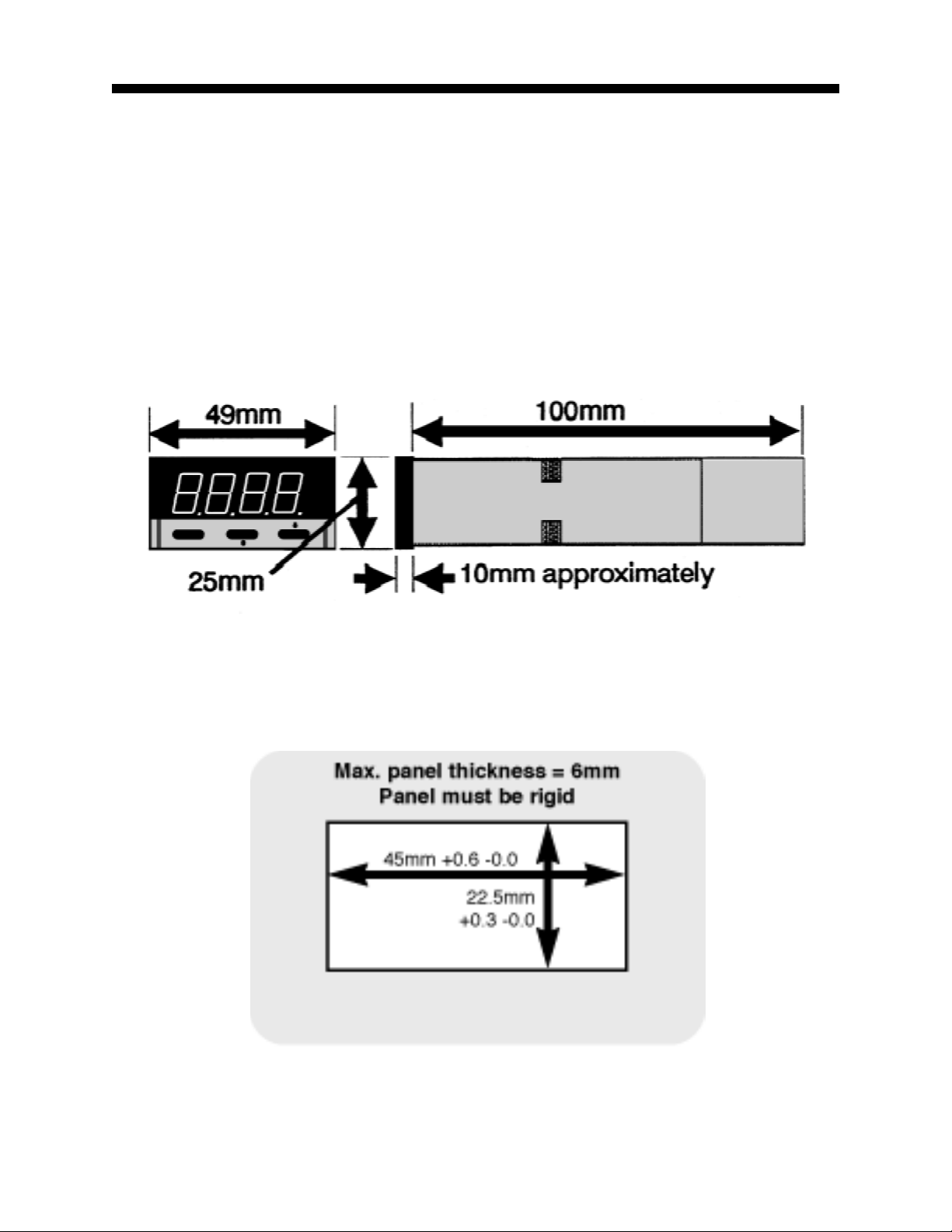
Figure 1-1 Main Dimensions 5
Figure 1-2 Panel Cut-out Dimensions 5
Figure 2-1 Rear Terminal Connections 7
Figure 2-2 Mains (Line) Supply Connections 8
Figure 2-3 Low Voltage AC/DC Supply Connections 9
Figure 2-4 RS485 Line Termination 10
Table 4-1 Sensor Selection Codes 17
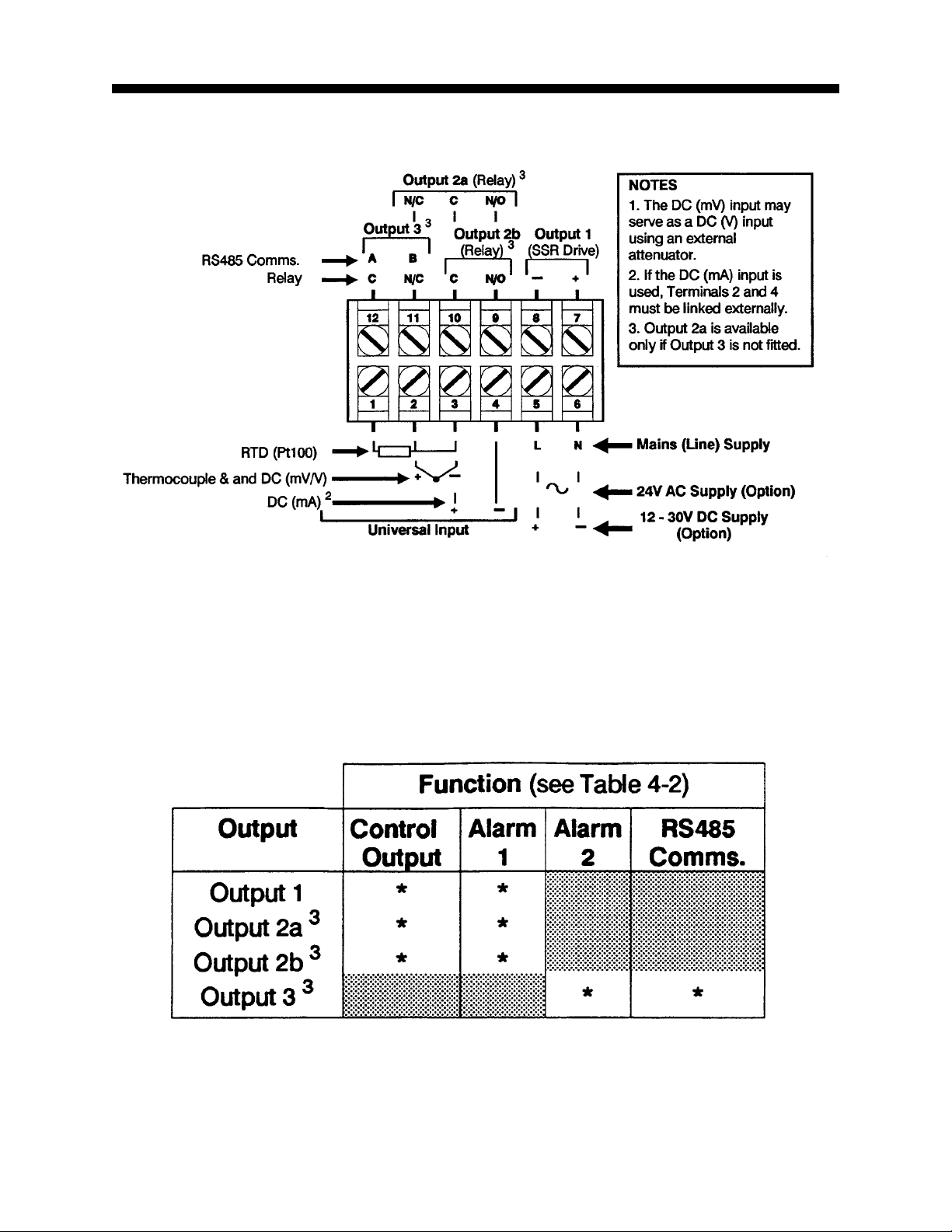
Table 4-2 Output Selection Codes 17
Form 4 Edition 1
Page 5
Installation - Panel-MountingInstallation - Panel-Mounting
Installation - Panel-Mounting
Installation - Panel-MountingInstallation - Panel-Mounting
1.11.1
1.1
1.11.1
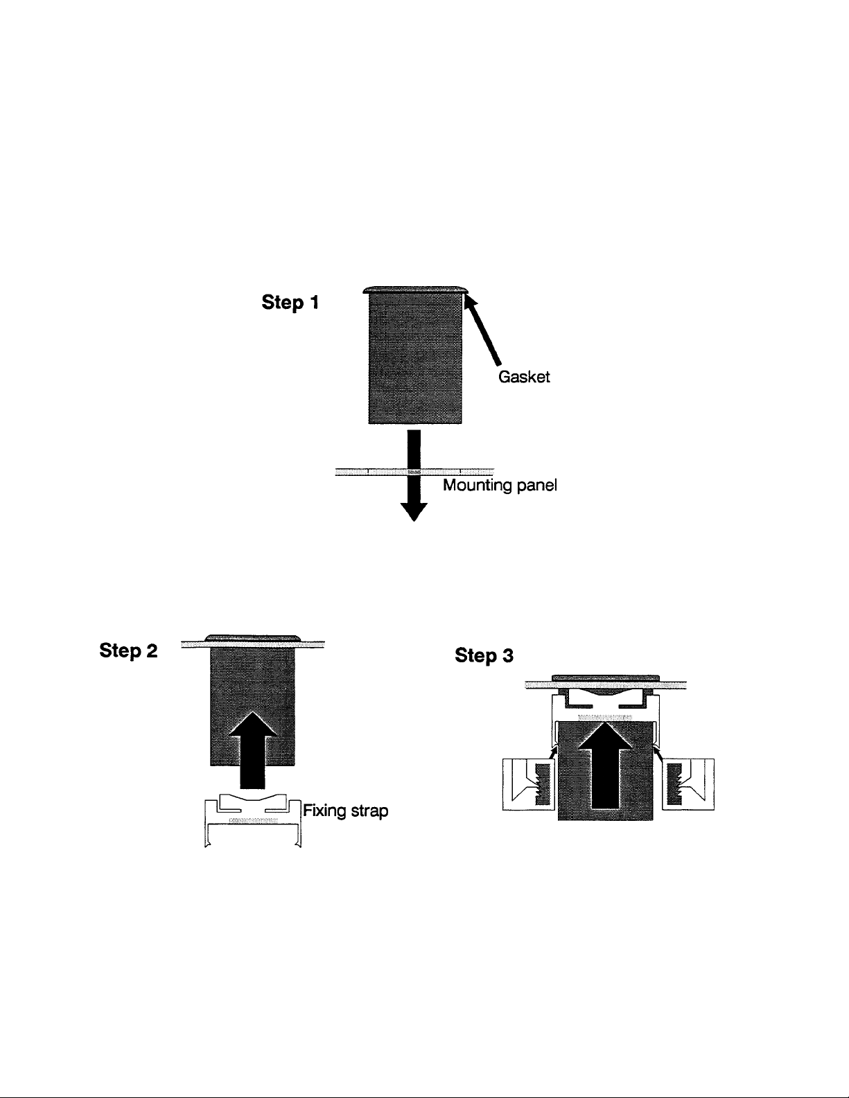
1. Remove the Controller from its packing. A panel gasket and a “no tools
required” fixing strap are supplied. Retain the packing for future use (e.g.
moving the Controller to a different site).
2. Examine the delivered items for damage or deficiencies. If any is found,
notify the carrier immediately. Check that the Product Code on the label
affixed to the Controller housing corresponds to that ordered.
UNPACKING THE INSTRUMENTUNPACKING THE INSTRUMENT
UNPACKING THE INSTRUMENT
UNPACKING THE INSTRUMENTUNPACKING THE INSTRUMENT
FIGURE 1-1FIGURE 1-1
FIGURE 1-1 Main Dimensions
FIGURE 1-1FIGURE 1-1
FIGURE 1-2FIGURE 1-2
FIGURE 1-2 Panel Cut-out Dimensions
FIGURE 1-2FIGURE 1-2
Edition 1 5 Form
Page 6
1.21.2
1.2
1.21.2
INSTALLING THE CONTROLLER IN THE MOUNTING PANELINSTALLING THE CONTROLLER IN THE MOUNTING PANEL
INSTALLING THE CONTROLLER IN THE MOUNTING PANEL
INSTALLING THE CONTROLLER IN THE MOUNTING PANELINSTALLING THE CONTROLLER IN THE MOUNTING PANEL
CAUTION: Do not remove the front panel gasket from the Controller , as this
may cause inadequate clamping of the Controller to the mounting panel.
Ensure that this gasket is not distorted and that the Controller is positioned
squarely against the mounting panel. Apply pressure to the front panel
bezel only .
Controller
Form 6 Edition 1
Page 7
Installation - Wiring ConnectionsInstallation - Wiring Connections
Installation - Wiring Connections
Installation - Wiring ConnectionsInstallation - Wiring Connections
FIGURE 2-1FIGURE 2-1
FIGURE 2-1 Rear Terminal Connections
FIGURE 2-1FIGURE 2-1
Edition 1 7 Form
Page 8
2.12.1
2.1
2.12.1
MAINS (LINE) SUPPLYMAINS (LINE) SUPPLY
MAINS (LINE) SUPPLY
MAINS (LINE) SUPPLYMAINS (LINE) SUPPLY
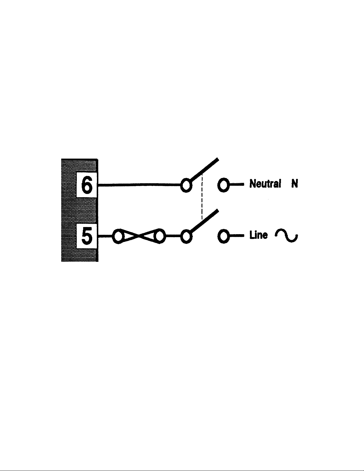
This version of the Controller will operate on a 96 - 264V AC 50/60Hz mains
(line) supply. The power consumption is approximately 4W.
CAUTION: This equipment is designed for installation in an enclosure
which provides adequate protection against electric shock. Local
regulations regarding electrical installation should be rigidly observed.
Consideration should be given to prevention of access to the power
terminations by unauthorized personnel. Power should be connected via a
two-pole isolating switch (preferably situated near the Controller) and a 1A
fuse, as shown in Figure 2-2.
FIGURE 2-2FIGURE 2-2
FIGURE 2-2 Mains (Line) Supply Connections
FIGURE 2-2FIGURE 2-2
If the contacts of the relay output(s) are used to carry mains (line) voltage, it
is recommended that the relay contacts mains (line) supply should be
switched and fused in a similar manner but should be separate from the
Controller mains (line) supply.
2.22.2
2.2
2.22.2
LOW VOLTAGE (24V AC/DC) SUPPLY - OPTIONLOW VOLTAGE (24V AC/DC) SUPPLY - OPTION
LOW VOLTAGE (24V AC/DC) SUPPLY - OPTION
LOW VOLTAGE (24V AC/DC) SUPPLY - OPTIONLOW VOLTAGE (24V AC/DC) SUPPLY - OPTION
This version of the Controller will operate on 12 - 24V AC 50/60Hz or 12 30V DC supply . The power consumption is approximately 4W. The
connections are shown in Figure 2-3; these should be made via a two-pole
isolating switch and a 315mA slow-blow (anti-surge Type T) fuse.
Form 8 Edition 1
Page 9

FIGURE 2-3FIGURE 2-3
FIGURE 2-3 Low Voltage AC/DC Supply Connections
FIGURE 2-3FIGURE 2-3
2.32.3
2.3
2.32.3
THERMOCOUPLE INPUTTHERMOCOUPLE INPUT
THERMOCOUPLE INPUT
THERMOCOUPLE INPUTTHERMOCOUPLE INPUT
The correct type of thermocouple extension leadwire or compensating cable
must be used for the full distance between the Controller and the thermocouple, ensuring that the correct polarity is observed throughout. Joints in
the cable should be avoided, if possible.
NOTE: Do not run the thermocouple cables adjacent to power-carrying
conductors. If the wiring is run in a conduit, use a separate conduit for the
thermocouple wiring. If the thermocouple is grounded, this must be done at
one point only. If the thermocouple extension lead is shielded, the shield
must be grounded at one point only.
2.42.4
2.4
2.42.4
RTD INPUTSRTD INPUTS
RTD INPUTS
RTD INPUTSRTD INPUTS
The compensating lead should be connected to Terminal 3. For two-wire
RTD inputs, Terminals 2 and 3 should be linked. The extension leads should
be of copper and the resistance of the wires connecting the resistance
element should not exceed 5 ohms per lead (the leads should be of equal
length).
2.52.5
2.5
2.52.5
DC INPUTSDC INPUTS
DC INPUTS
DC INPUTSDC INPUTS
DC (mV) inputs are connected to Terminals 2 and 3 in the polarity shown in
Figure 2-1; DC (V) inputs are connected to the same terminals with the
same polarity but require an external attenuator. DC (mA) inputs are connected to Terminals 3 and 4 in the polarity shown in Figure 2-1 with Terminals 2 and 4 linked externally.
2.62.6
2.6
2.62.6
RELAY OUTPUTS (OUTPUT 2 & OUTPUT 3)RELAY OUTPUTS (OUTPUT 2 & OUTPUT 3)
RELAY OUTPUTS (OUTPUT 2 & OUTPUT 3)
RELAY OUTPUTS (OUTPUT 2 & OUTPUT 3)RELAY OUTPUTS (OUTPUT 2 & OUTPUT 3)
The contacts are rated at 2A resistive at 120/240V AC.
Edition 1 9 Form
Page 10
2.72.7
2.7
2.72.7
This output produces a time-proportioned non-isolated DC signal (0 - 10V
nominal, into 500Ω minimum).
SSR DRIVE OUTPUT (OUTPUT 1)SSR DRIVE OUTPUT (OUTPUT 1)
SSR DRIVE OUTPUT (OUTPUT 1)
SSR DRIVE OUTPUT (OUTPUT 1)SSR DRIVE OUTPUT (OUTPUT 1)
2.82.8
2.8
2.82.8
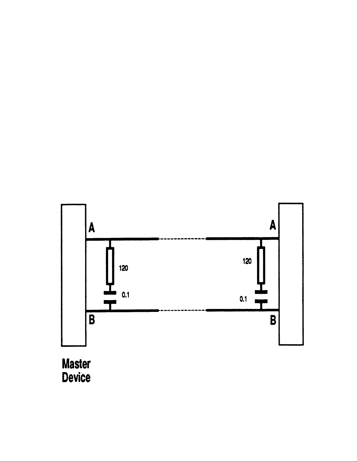
The “A” terminal (Terminal 12) on the Controller should be connected to the
“A” terminal on the master device; the “B” terminal (Terminal 11) on the
Controller should be connected to the “B” terminal on the master device.
This instrument uses standard RS485 devices, isolated from all other inputs
and outputs. The devices present a 1/4-unit load to the RS485 line. Generally, termination will not be required but may be necessary for line lengths
greater than 100 metres. Where termination is necessary, it is recommended that a 120Ω resistance in series with a 0.1µF capacitor be used at
each end of the line (see Figure 2-4).
RS485 COMMUNICATIONSRS485 COMMUNICATIONS
RS485 COMMUNICATIONS
RS485 COMMUNICATIONSRS485 COMMUNICATIONS
Controller
FIGURE 2-4FIGURE 2-4
FIGURE 2-4 RS485 Line Termination
FIGURE 2-4FIGURE 2-4
Form 10 Edition 1
Page 11

Front PanelFront Panel
Front Panel
Front PanelFront Panel
3.13.1
3.1
3.13.1
3.23.2
3.2
3.23.2
INDICATORSINDICATORS
INDICATORS
INDICATORSINDICATORS
KEYSKEYS
KEYS
KEYSKEYS
Green: OFF - PV < SP
ON - PV = SP
Flashing - PV > SP
Yellow: OFF - Normal Operation
ON - Control Setup
Flashing - Instrument Configuration
Red: Flashes when alarm(s) active
Scroll key
All Modes except Calibration:
If parameter value displayed, shows parameter
legend (for 1.5 seconds). If legend displayed,
shows value of next parameter.
Calibration:
Starts calibration phase.
Down key
Normal Operation:
Decrements parameter value. With process variable
displayed, dis-engages Pre-Tune*. Also confirms
request for entry into
Control Setup/Instrument Configuration:
Decrements parameter value.
Calibration:
Steps to previous calibration phase.
Edition 1 11 Form
Instrument Configuration
.
Page 12

Up key
Normal Operation:
Decrements parameter value. With process variable
displayed, requests Pre-Tune*.
Control Setup/Instrument Configuration:
Decrements parameter value.
Calibration:
Steps to next calibration phase.
Scroll & Down keys
Normal Operation:
Enters
Calibration
.
Scroll & Up keys
Normal Operation:
Requests entry into
Normal Operation:
Control Setup
Enters
Control Setup/Instrument
Configuration/Calibration:
Returns to
Normal Operation
Instrument Configuration
Down & Up keys
.
.
.
Form 12 Edition 1
Page 13

Instrument ConfigurationInstrument Configuration
Instrument Configuration
Instrument ConfigurationInstrument Configuration
4.14.1
4.1
4.14.1
ENTRY INTO INSTRUMENT CONFIGURATION MODEENTRY INTO INSTRUMENT CONFIGURATION MODE
ENTRY INTO INSTRUMENT CONFIGURATION MODE
ENTRY INTO INSTRUMENT CONFIGURATION MODEENTRY INTO INSTRUMENT CONFIGURATION MODE
1. Hold down Scroll and Up keys
simultaneously until the display begins to flash.
2. When display begins to flash, release the
Scroll and up keys and press the Down key.
4.24.2
4.2
4.24.2
The Scroll key is used to step through the parameters in the following
manner:
Edition 1 13 Form
PARAMETER SEQUENCEPARAMETER SEQUENCE
PARAMETER SEQUENCE
PARAMETER SEQUENCEPARAMETER SEQUENCE
Page 14

The parameter sequence is as follows:
Scroll key steps through displays; Up/Down keys adjust displayed values.
1. Appears only if sensor selected is DC (mA, Mv or V).
2. Appears only if Comms. configured and fitted.
3. Appears only if Output 3 configured and fitted.
4. Appears only if PID control is configured.
Form 14 Edition 1
Page 15

4.2.14.2.1
4.2.1
4.2.14.2.1
Adjustment RangesAdjustment Ranges
Adjustment Ranges
Adjustment RangesAdjustment Ranges
Continued on next page
Edition 1 15 Form
Page 16

Continued from previous page
Form 16 Edition 1
Page 17

TABLE 4-1TABLE 4-1
TABLE 4-1 Sensor Selection Codes
TABLE 4-1TABLE 4-1
TABLE 4-2TABLE 4-2
TABLE 4-2 Output Selection Codes
TABLE 4-2TABLE 4-2
Edition 1 17 Form
Page 18

4.2.24.2.2
4.2.2
4.2.24.2.2
DEFAULT VALUESDEFAULT VALUES
DEFAULT VALUES
DEFAULT VALUESDEFAULT VALUES
4.34.3
4.3
4.34.3
EXIT FROM INSTRUMENT CONFIGURATION MODEEXIT FROM INSTRUMENT CONFIGURATION MODE
EXIT FROM INSTRUMENT CONFIGURATION MODE
EXIT FROM INSTRUMENT CONFIGURATION MODEEXIT FROM INSTRUMENT CONFIGURATION MODE
To exit from Instrument Configuration Mode:
Hold down the Up and Down keys
for three seconds
The instrument will then return to Normal Operation Mode via an instrument
reset and self-test sequence.
NOTE: If there is no key activity for five minutes in Instrument Configuration
Mode, an automatic return is made to Normal Operation Mode (via an instrument reset and self-test sequence).
Form 18 Edition 1
Page 19

Operation ModeOperation Mode
Operation Mode
Operation ModeOperation Mode
Scroll Key
Down Key
Up Key
INDICATORS
Green:
Yellow:
Red:
Edition 1 19 Form
OFF – Process Variable less than Setpoint
ON – Process Variable equals Setpoint
Flashing – Process Varible greater than Setpoint
OFF – Normal Operation
ON – Control Setup
Flashing – Alarm(s) active
Page 20

5.15.1
5.1
5.15.1
NORMAL OPERATION (Yellow LED OFF)NORMAL OPERATION (Yellow LED OFF)
NORMAL OPERATION (Yellow LED OFF)
NORMAL OPERATION (Yellow LED OFF)NORMAL OPERATION (Yellow LED OFF)
In this mode, the display normally shows the process variable value. Use
the Scroll key to step through a sequence of parameters as follows:
The following parameters are available in Normal Operation.
Form 20 Edition 1
Page 21

5.1.15.1.1
5.1.1
5.1.15.1.1
EASY TUNEEASY TUNE
EASY TUNE
EASY TUNEEASY TUNE
If the Controller has been configured for Easy T une operation, all tuning is
executed automatically; no operator action is required.
5.2.25.2.2
5.2.2
5.2.25.2.2
MANUAL TUNING WITH PRE-TUNEMANUAL TUNING WITH PRE-TUNE
MANUAL TUNING WITH PRE-TUNE
MANUAL TUNING WITH PRE-TUNEMANUAL TUNING WITH PRE-TUNE
When the Controller is configured for Manual T uning, the Pre-T une facility is
available. Pre-T une is used to optimise system start-up (normally after
power-up or after a major change to the process being controlled). To activate Pre-T une:
NOTE: Pre-Tune cannot be activated if the Process Variable is within 5% of
input span from the setpoint.
To dis-engage Pre-Tune:
NOTE: Pre-Tune is a single-shot operation and, therefore, when it is completed, Pre-Tune will dis-engage itself automatically.
Edition 1 21 Form
Page 22

Control Setup (Yellow LED ON)Control Setup (Yellow LED ON)
Control Setup (Yellow LED ON)
Control Setup (Yellow LED ON)Control Setup (Yellow LED ON)
To enter Control Setup mode, press the Up and Down keys simultaneously
for more than three seconds. The same key action exits this mode. The
parameters are as follows:
Form 22 Edition 1
Page 23

6.16.1
6.1
6.16.1
ADJUSTMENT RANGESADJUSTMENT RANGES
ADJUSTMENT RANGES
ADJUSTMENT RANGESADJUSTMENT RANGES
6.26.2
6.2
6.26.2
DEFAULT VALUES/SETTINGSDEFAULT VALUES/SETTINGS
DEFAULT VALUES/SETTINGS
DEFAULT VALUES/SETTINGSDEFAULT VALUES/SETTINGS
Edition 1 23 Form
Page 24

Calibration ModeCalibration Mode
Calibration Mode
Calibration ModeCalibration Mode
The Controller is shipped from the factory ready-calibrated and normally
does not need further calibration. However, some users may have a legal
requirement for annual calibration. The procedures set out in this Section
serve that purpose.
7.17.1
7.1
7.17.1
PRE-REQUISITESPRE-REQUISITES
PRE-REQUISITES
PRE-REQUISITESPRE-REQUISITES
The Calibration Mode has four phases. In addition to the Controller to be
calibrated, each phase requires the appropriate input to be fitted before that
phase is executed. These pre-requisites are shown in the box below.
NOTE: These procedures should be implemented only by personnel competent and authorized to do so.
CALIBRATION PRE-REQUISITES
Phase 1 - DC mV Linear Input: 50mV DC across Terminals 2 & 3 in the
polarity shown in Figure 2-1.
Phase 2 - RTD Input: 200W across Terminals 1 & 2 with com-
pensating lead connected to Terminal 3.
Phase 3 - DC mA Input: 20mA current source connected to Termi-
nals 3 & 4 in the polarity shown in Figure
2-1.
Phase 4 - Thermocouple Input/CJC: 0
Form 24 Edition 1
o
C reference facility , Type K thermocouple leads (or equivalent) connected to
Terminals 2 & 3.
Page 25

7.27.2
7.2
7.27.2
Entry into Calibration ModeEntry into Calibration Mode
Entry into Calibration Mode
Entry into Calibration ModeEntry into Calibration Mode
To enter Calibration Mode:
1. Power-down
the Controller.
3. As the first key action after power-up, hold
down the Scroll and Down keys for at least six
seconds.
2. Power-up the
Controller .
The Controller will then enter the Calibration Mode and will display:
indicating that the first calibration phase is ready to be executed.
Edition 1 25 Form
Page 26

7.37.3
7.3
7.37.3
Calibration ProcedureCalibration Procedure
Calibration Procedure
Calibration ProcedureCalibration Procedure
n Use Up key (step forward) or Down key (step backward) to select required phase.
n Use Scroll key to start selected phase.
n If FAIL displayed, use Up or Down key to return to start of failed phase.
Form 26 Edition 1
Page 27

7.47.4
7.4
7.47.4
EXITING CALIBRATION MODEEXITING CALIBRATION MODE
EXITING CALIBRATION MODE
EXITING CALIBRATION MODEEXITING CALIBRATION MODE
To exit Calibration Mode:
Hold down the Up and Down keys for three
seconds.
The Controller will then return to Normal Operation Mode
NOTE: If there is no key activity for five minutes in Calibration Mode, an
automatic return is made to Normal Operation Mode.
Edition 1 27 Form
Page 28

Appendix AAppendix A
Appendix A
Appendix AAppendix A
Product SpecificationProduct Specification
Product Specification
Product SpecificationProduct Specification
UNIVERSAL INPUTUNIVERSAL INPUT
UNIVERSAL INPUT
UNIVERSAL INPUTUNIVERSAL INPUT
Sample Rate: 4 samples/second
Digital Filter: Filter time constant selectable from front panel. Adjust-
ment range 0.0 to 100.0 seconds in 0.5 second
increments.
Input Resolution: 14-bit resolution approximately. Always at least four
times better than the display resolution.
Input Impedance: >10MΩ resistive.
Isolation: 240V ac isolation from all outputs except SSR Drive.
Input Offset: Adjustable ± input span, subject to display limit on
negative values (-1999).
Thermocouple InputThermocouple Input
Thermocouple Input
Thermocouple InputThermocouple Input
Ranges selectable from the front panel are:
Calibration: Complies with BS4937, NBS125 and IEC584.
Sensor Break Detection: Break detected within two seconds.
Form 28 Edition 1
Page 29

RTD InputRTD Input
RTD Input
RTD InputRTD Input
Ranges selectable from the front panel are:
Type and Connection: Three-wire Pt100.
Calibration: Complies with BS1904 and DIN43760.
Lead Compensation: Automatic scheme.
RTD Sensor Current: 150µA approximately.
Sensor Break detection: Break detected within two seconds.
DC InputDC Input
DC Input
DC InputDC Input
Ranges selectable from the front panel are:
OUTPUTSOUTPUTS
OUTPUTS
OUTPUTSOUTPUTS
Output 1 - SSR Drive (Standard)
Usage: Selectable - may be used as Control Output
or Alarm 1 Output.
Drive Capability: >10Vdc into 500Ω minimum (50mA
maximum).
Isolation: Not isolated from input.
Output 2 - Relay (Standard)Output 2 - Relay (Standard)
Output 2 - Relay (Standard)
Output 2 - Relay (Standard)Output 2 - Relay (Standard)
Usage: Selectable - may be used as Control Output
or Alarm 1 Output.
Contact Type: Single pole, single throw (SPST).
Edition 1 29 Form
Page 30

Rating: 2A resistive at 120/240V ac.
Life: >500,000 operations at rated voltage &
current.
Isolation: Inherent.
Output 3 - Relay or Communications (Options)Output 3 - Relay or Communications (Options)
Output 3 - Relay or Communications (Options)
Output 3 - Relay or Communications (Options)Output 3 - Relay or Communications (Options)
Relay Output
Usage: Selectable - may be used as Alarm 2.
Contact Type: Single pole, single throw (SPST).
Rating: 2A resistive at 120/240V ac.
Life: >500,000 operations at rated voltage &
current.
Isolation: Inherent.
Communications Port
T ype: Serial Asynchronous UAR T -to-UART link.
Data Format: 1 start bit, selectable parity (odd, even or
none), 8 data bits, 1 stop bit.
Physical Layer: RS485 (two-wire).
Transmitter Drive Capability: 32 standard RS485 unit loads.
Receiver Bus Loading: 0.25 standard RS485 unit load.
Presentation Layer: MODBUS RTU protocol.
Maximum Number of Zones: 128.
Baud Rate: Selectable from front panel in the range
9600, 4800, 2400 and 1200.
Zone Address Range: 1 to 128.
LOOP CONTROLLOOP CONTROL
LOOP CONTROL
LOOP CONTROLLOOP CONTROL
Control Algorithms: Direct/reverse-acting PID or On/Off.
Automatic Tuning Types: Pre-Tune or Hands-OFF EASY TUNE.
Proportional Band: 0.5% to 999.9% at 0.1% resolution.
Reset
(Integral Time Constant): 1 second to 99 minutes 59 seconds and OFF
(greater than 99 minutes 59 seconds).
Form 30 Edition 1
Page 31

Rate
(Derivative Time Constant: 0 (OFF) to 9 minutes 59 seconds.
Bias (Manual Reset): 0 to 100%.
On/Off Hysteresis: 0.1% to 10.0% of input span.
Output Cycle Time: Selectable from 0.5sec. (SSR Drive only), 1,
2, 4, 8, 16, 32, 64, 128, 256, 512 secs.
Setpoint Range: Bounded by Input Range Maximum and Input
Range Minimum. Setpoint lockable.
ALARM CONTROLALARM CONTROL
ALARM CONTROL
ALARM CONTROLALARM CONTROL
Max. Number of Alarms: Two, if two physical outputs are available.
Alarm TypesProcess High: Input Range Minimum to Input Range
Maximum.
Process Low: Input Range Minimum to Input Range
Maximum.
Deviation (High/Low): ±input span (negative values limited by dis-
play to -1999).
Band: 1 LSD to input span.
PERFORMANCEPERFORMANCE
PERFORMANCE
PERFORMANCEPERFORMANCE
Reference ConditionsReference Conditions
Reference Conditions
Reference ConditionsReference Conditions
Generally as BS5558.
Ambient Temperature: 20
o
C±2oC.
Relative Humidity: 60 to 70% non-condensing.
Supply Voltage: 90 to 254V ac 50Hz æ 1%.
Source Resistance: <10Ω for thermocouple.
Lead Resistance: <0.1Ω/lead balanced (Pt100).
Performance Under Reference ConditionsPerformance Under Reference Conditions
Performance Under Reference Conditions
Performance Under Reference ConditionsPerformance Under Reference Conditions
Common Mode Rejection: >120dB @ 50/60Hz giving negligible effect at
up to 264V at 50/60Hz.
Series Mode Rejection: >500% of input span at 50/60Hz giving negli-
gible effect.
Edition 1 31 Form
Page 32

Thermocouple Inputs
Measurement Accuracy: 0.1% of input span ±1 LSD typical (0.25% for
T ypes J and T). NOTE: Reduced performance
for Type B 100 to 600
Linearisation Accuracy: Better than ±0.2
o
range (±0.05
C typical).
Better than ±0.5
o
o
o
C (and oF equivalent).
C at any point for any 0.1oC
C at any point for any 1oC
range.
o
Cold Junction Compensation: Better than ±0.7
C.
RTD Inputs
Measurement Accuracy: ±0.1% of input span ±1 LSD.
Linearisation Accuracy: Better than ±0.2
range (±0.05
Better than ±0.5
o
C at any point for any 0.1oC
o
C typical).
o
C at any point for any 1oC
range.
DC mA/mV Inputs
Measurement Accuracy: ±0.1% of input span ±1 LSD.
Operating ConditionsOperating Conditions
Operating Conditions
Operating ConditionsOperating Conditions
Ambient T emperature
o
(Operating): 0
C to 55oC.
Ambient T emperature
(Storage): -20
o
C to 80oC.
Relative Humidity: 20% to 95% non-condensing.
Supply Voltage: 90 to 264V ac 50/60Hz.
Source Resistance: 1000Ω maximum (thermocouple).
Lead Resistance: 50Ω/lead maximum (Pt100).
Performance Under Operating Conditions:Performance Under Operating Conditions:
Performance Under Operating Conditions:
Performance Under Operating Conditions:Performance Under Operating Conditions:
Temperature Stability: 0.01% on input span/
o
C change in ambient
temperature (RTD and DC mA/mV 0.005% of
o
span/
C).
Form 32 Edition 1
Page 33

Cold Junction Compensation: Better than ±1oC.
Supply voltage Influence: Negligible.
Relative Humidity Influence: Negligible.
Sensor Resistance Influence: Thermocouple 1000Ω <0.1% of span error.
RTD Pt100 50Ω/lead <0.25% of span error.
ENVIRONMENTALENVIRONMENTAL
ENVIRONMENTAL
ENVIRONMENTALENVIRONMENTAL
Operating Conditions: See PERFORMANCE.
EMI Immunity: Complies with BS EN 50082 Parts 1 (1992)
and 2 (1995).
EMI Emissions: Complies with BS EN 50081 Parts 1 (1992)
and 2 (1994).
Safety Considerations: Complies with BS EN 61010 Part 1 (1993) in
so far as it applies.
Supply Voltage: 90 - 264V ac 50/60Hz (standard);
12 - 24V ac 50/60Hz or 12 - 30V dc (option).
Power Consumption: 4W maximum.
Front Panel Sealing: To IP66 (similar to NEMA4).
PHYSICALPHYSICAL
PHYSICAL
PHYSICALPHYSICAL
Dimensions: Behind-panel depth 100mm. Front face
25mm high x 49 mm wide.
Mounting: Plug-in with panel-mounting sleeve. Panel
cutout 45mm x 22.5mm.
Terminals: Screw type.
Weight: 100g.
Edition 1 33 Form
 Loading...