

Page 1
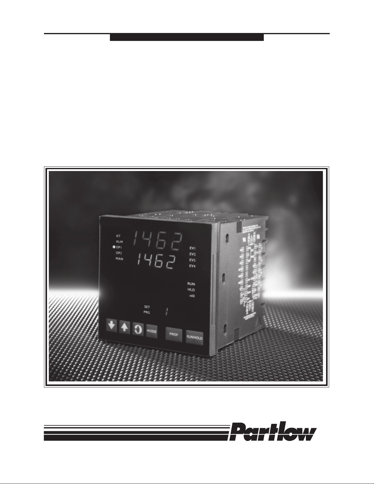
MIC 1462
1/4 DIN SETPOINT PROGRAMMER
OPERATORS MANUAL
FORM 3806
EDITION 1 © Jan.1998
PRICE $10.00
Brand
Page 2

Information in this installation, wiring, and operation manual is subject to change
without notice. One manual is provided with each instrument at the time of shipment. Extra copies are available at the price published on the front cover.
Copyright © January 1998, The Partlow-West Company, all rights reserved. No
part of this publication may be reproduced, transmitted, transcribed or stored in a
retrieval system, or translated into any language in any form by any means without
the written permission of the Partlow-West Company.
This is the First Edition of the MIC 1462 manual. It was written and produced
entirely on a desk-top-publishing system. Disk versions are available by written
request to the Partlow-West Company Publications Department.
We are glad you decided to open this manual. It is written so that you can take full
advantage of the features of your new MIC 1462 setpoint programmer.
NOTE:
It is strongly recommended that Partlow Brand equipped
applications incorporate a high or low limit protective device which will shut down the equipment at a preset process
condition in order to preclude possible damage to property
or products.
Page 3

Table of Contents
Section 1 - General Page
1.1 Product Description 1
Section 2 - Installation & Wiring
2.1 Unpacking Procedure 3
2.2 Panel Mounting 3
2.3 Preparation for Wiring 5
2.4 Input Connections 12
2.5 Output Connections 15
Section 3 - Operation
3.1 Power-up Procedure 23
3.2 Keypad Operation 23
3.3 Indicators 25
3.4 Displays 26
3.5 Alarm Status Indication 26
3.6 Viewing Operating Modes 27
3.7 Adjusting the Setpoint 27
3.8 Viewing Input Values 28
3.9 Base Mode/Off Mode Outputs 29
3.10 Viewing the Time and Day 29
3.11 Manual Control 29
3.12 Using the Pre-Tune Facility 30
3.13 Using the Self-Tune Facility 31
Section 4 - Configuration
4.1 Entry into Configuration 32
4.2 Hardware Definition Mode 33
4.3 Configuration Mode Parameters 36
4.4 Exit from Configuration Mode 41
Section 5 - Tune Mode
5.1 Tune Parameters 43
5.2 Exiting Tune Mode 48
Section 6 - Alarm Mode
6.1 Alarm Parameters 49
6.2 Alarm Inhibit 53
6.3 Loop Alarm and Loop Alarm Time 53
i MIC 1462 ManualEdition 1
Page 4

Section 7 - Profile Define Mode
7.1 Entry into Profile Define 58
7.2 Parameters Common to All Profiles 59
7.3 Parameters which apply to a Specific Profile 62
7.4 Parameters in any/each Segment 66
7.5 Using Join, Repeat, and End Segments 69
7.6 Basic Rules to Remember 71
7.7 Exiting Program Define Mode 71
Section 8 - Programs
8.1 Selecting and Running a Program 72
8.2 Changing Timebase 72
8.3 Holding Manually 72
8.4 Jumping to Next Segment 73
8.5 Viewing Program Status 73
8.6 Aborting a Program 74
8.7 End of Progam Indication 74
8.8 Accessing Modes of the Controller 75
Section 9 - Test Mode 76
Section 10- Calibration Mode
10.1 Calibration Procedure 77
10.2 Exit From Calibration 80
10.3 Calibration Check 80
Appendices
A - Input Range Codes 81
B - Board Layout - Jumper positioning 83
Figure B-1 PCB Positions 83
Figure B-2 Output 2/Output 3 Removal 84
Figure B-3 CPU PWA 85
Figure B-4 PSU PWA with Relay or SSR Out.1 86
Figure B-5 PSU PWA with DC Output 1 87
Figure B-6 Option PWA DC Output 2/Output 3 88
C - Specifications 89
D - Model Number Hardware Matrix 98
E - Software Reference Sheet 99
MIC 1462 Manual
ii
Edition 1
Page 5

Figures
Figure 1-1 Front Panel 2
Figure 2-1 Panel Cut-Out Dimensions 3
Figure 2-2 Main Dimensions 4
Figure 2-3 Panel Mounting the controller 5
Figure 2-4 Noise Suppression 8
Figure 2-5 Noise Suppression 8
Figure 2-6 Rear Terminal Connections 10
Figure 2-6A Rear Terminal Connections 11
Figure 2-7 Main Supply 12
Figure 2-7A 24V Nominal AC/DC Supply 13
Figure 2-8 Thermocouple (T/C) Input 13
Figure 2-9 RTD Input 13
Figure 2-10 Volt, mV Input 14
Figure 2-11 mA DC Input 14
Figure 2-12 Remote Digital Communications 15
Figure 2-13 Relay Output 1 15
Figure 2-14 SSR Driver Output 1 15
Figure 2-15 mADC Output 1 16
Figure 2-16 Relay Output 2 16
Figure 2-17 SSR Driver Output 2 16
Figure 2-18 mADC Output 2 17
Figure 2-19 Transmitter Power Supply Out 2 17
Figure 2-20 Relay Output 3 17
Figure 2-21 SSR Driver Output 3 18
Figure 2-22 mADC Output 3 18
Figure 2-23 Transmitter Power Supply Out 3 18
Figure 2-24 End of Program Output 19
Figure 2-25 Event Outputs 19
Figure 2-26 Remote Program Output 20
Figure 2-27 Valve Motor Drive 21
Figure 2-28 VMD with Interlock 22
Figure 5-1 Proportional Band and Deadband/Overlap 47
Figure 6-1 Alarm Operation 55
Figure 6-2 Alarm Hysteresis Operation 57
Figure 7-1 Auto Hold Operation 65
Figure 10-1 Jumper Positions Calibration 79
Figure 10-2 Connections for Calibration 80
iii MIC 1462 ManualEdition 1
Page 6

MIC 1462 Manual
iv
Edition 1
Page 7

Section 1 - General
1.1 PRODUCT DESCRIPTION
This instrument is a powerful, easy-to-use 1/4 DIN setpoint programmer
with full PID control capability (complete with Self-Tune and Pre-Tune facilities).
Its standard features include:
• Up to eight programs of up to 16 free-format (e.i. dwell, ramp, join, or
end) segments each.
• Facility to join programs to one another in any sequence (maximum
program length 121 segments)
• User can change currently-running program segment.
• Delayed Start of Program facility
• End of Program relay output
• Universal input-thermocouple, RTD (PT100) or DC linear user-selectable.
• Universal power supply (90 -264V AC 50/60 Hz)
• Configurable from front panel
• Comprehensive front panel displays
• Front panel sealing to NEMA 4 standard
• Behind-panel depth only 100mm (3.94 inches)
• Power Failure Recovery
Optional features include:
• Remote control and selection of program (plug-in option)
• Up to four Event relay outputs (plug-in option)
• Second control output
• Recorder output (setpoint or process variable)
• RS-485 serial communications
• User-definable program tag names
• Support software (Off-line Configurator, On-line Graphic Program
Editor) - operates via RS-485 communications link.
• Real Time Clock
1 MIC 1462 ManualEdition 1
Page 8
The Setpoint Programmer has numerous operating modes:
Base Mode: Day to day PID control operations with no program running.
In this mode, a program may be selected to run.
Profile Run Mode: A selected program is running, held or waiting for a
pre-defined delay before starting. In this mode, the operator can view
status and program information.
Profile Define Mode: Used to view/create/edit programs. this mode is
entered either from Base Mode (selected program may be edited/created) or from Program Run Mode (currently-running program may be
edited).
Controller Define Mode: Used to define the controller characteristics.
Tune: Used to adjust tuning parameters
Alarm: Used to define and set alarms
Enable: Provides a means of enabling or disabling access to setpoint
changes and each of the non-control modes.
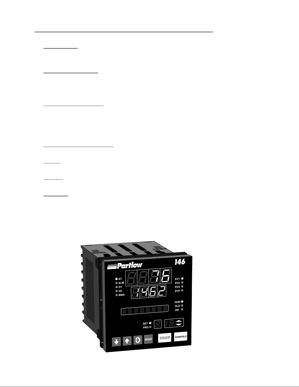
FIGURE 1-1
Front Panel
2
MIC 1462 Manual
2
Edition 1
Page 9

Section 2 - Installation & Wiring
2.1 UNPACKING PROCEDURE
1. Remove the instrument from its packing. The instrument is supplied
with a panel gasket and push-fit strap. Retain the packing for future use,
should it be necessary to transport the instrument to a different site or
return it to the factory for repair/testing.
2. Examine the delivered items for damage or deficiencies. If any is
found, notify the carrier immediately. Check that the model number
shown on the label affixed to the instrument housing corresponds to that
ordered (see Appendix D).
2.2 PANEL-MOUNTING THE SETPOINT PROGRAMMER
The panel on which the instrument is to be mounted must be rigid and may
be up to 6.0 mm (.25 inches ) thick. The cutout required for a single instrument is shown in Figure 2-1.
FIGURE 2-1
Cut-Out Dimensions
92 mm +0.5 - 0.00
(3.62”+.020 - .000)
PANEL
CUTOUT
SIZE
92 mm + 0.5 - 0.0
(3.62” + .020 - .000)
3 MIC 1462 ManualEdition 1
Page 10
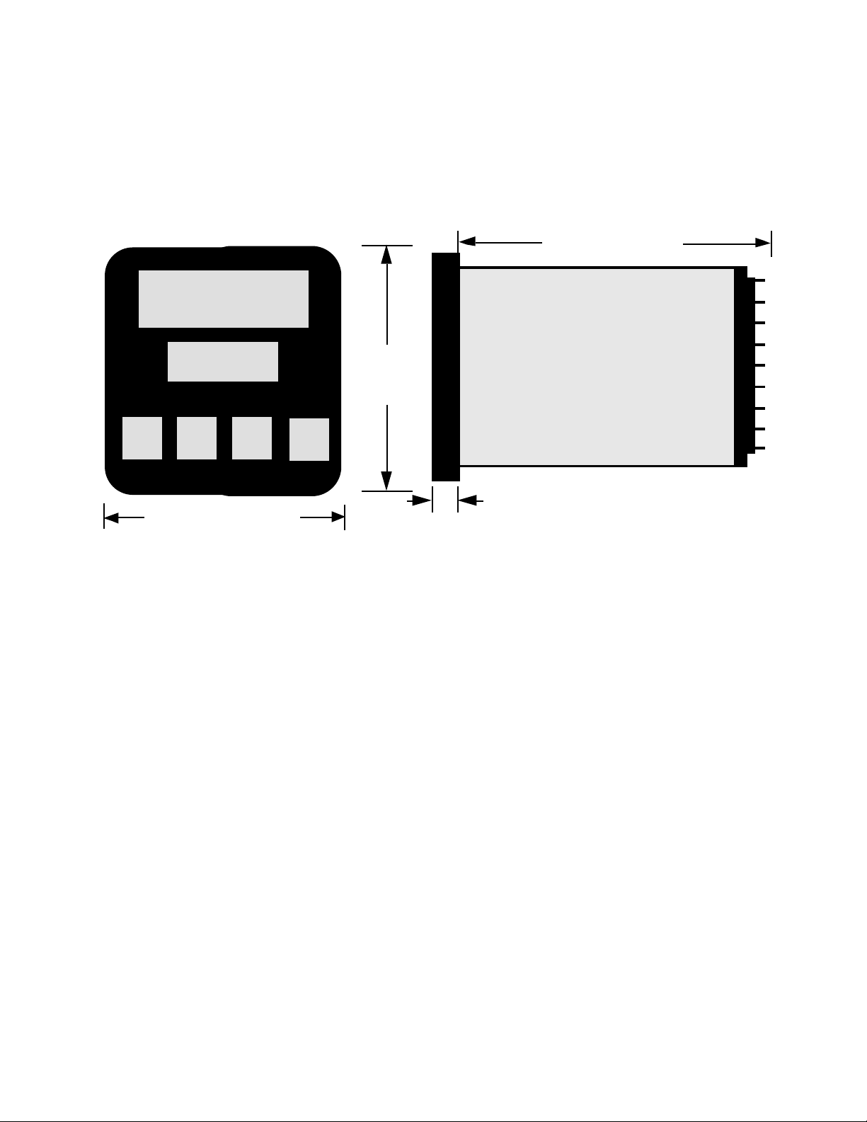
The main dimensions of the instrument are shown below.
FIGURE 2-2
Main Dimensions
100 mm (3.94 in.)
96 mm
(3.78 in)
Side View
96 mm
(3.78 in.)
Max. Panel Thickness 6.0mm (.25 inches)
10 mm (0.39 in.)
To panel-mount the instrument:
1. Insert the rear of the instrument housing through the cutout (from the
front of the mounting panel) and hold the instrument lightly in position
against the panel. Ensure that the panel gasket is not distorted and that
the instrument is positioned squarely against the mounting panel. Apply
pressure to the front panel bezel only.
Caution: Do not remove the panel gasket, as this may result
in inadequate clamping of the instrument in the panel.
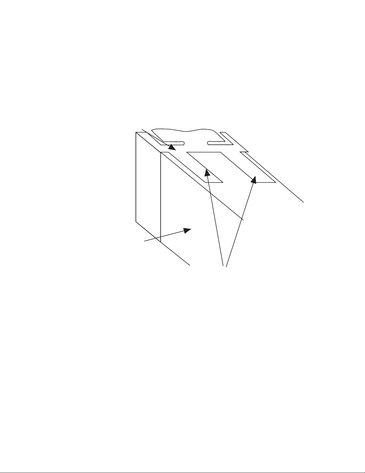
2. Slide the fixing strap in place (Figure 2-3) and push it forward until it
is firmly in contact with the rear face of the mounting panel (the tongues
on the strap should have engaged in matching rachet positions on the
instrument housing and the fixing strap springs should be pushing firmly
against the mounting panel rear face).
MIC 1462 Manual
4
Edition 1
Page 11
Once the instrument is installed in its mounting panel, it may be subsequently removed from its housing, if necessary, as described in Appendix B.
FIGURE 2-3
Panel-Mounting the Instrument
Mounting Clamp
Controller Housing
Tongues on mounting clamp engage in
ratchet slots on controller housing
2.3 PREPARATION FOR WIRING
Electrical noise is a phenomenon typical of industrial environments. The
following are guidelines that must be followed to minimize the effect of noise
upon any instrumentation.
2.3.1 INSTALLATION CONSIDERATIONS
Listed below are some of the common sources of electrical noise in the
industrial environment:
• Ignition Transformers
• Arc Welders
• Mechanical contact relay(s)
• Solenoids
5 MIC 1462 ManualEdition 1
Page 12

Before using any instrument near the device listed, the instructions below
should be followed:
1. If the instrument is to be mounted in the same panel as any of the
listed devices, separate them by the largest distance possible. For
maximum electrical noise reduction, the noise generating devices should
be mounted in a separate enclosure.
2. If possible, eliminate mechanical contact relay(s) and replace with
solid state relays. If a mechanical relay being powered by an instrument
output device cannot be replaced, a solid state relay can be used to
isolate the instrument.
3. A separate isolation transformer to feed only instrumentation should
be considered. The transformer can isolate the instrument from noise
found on the AC power input.
4. If the instrument is being installed on existing equipment, the wiring in
the area should be checked to insure that good wiring practices have
been followed.
2.3.2 AC POWER WIRING
Neutral (For 115 VAC)
It is good practice to assure that the AC neutral is at or near ground potential. To verify this, a voltmeter check between neutral and ground should be
done. On the AC range, the reading should not be more than 50 millivolts.
If it is greater than this amount, the secondary of this AC transformer supplying the instrument should be checked by an electrician. A proper neutral
will help ensure maximum performance from the instrument.
2.3.3 WIRE ISOLATION
Four voltage levels of input and output wiring may be used with the unit:
• Analog input or output (i.e. thermocouple, RTD, VDC, mVDC, or
mADC)
• SPDT Relays
• SSR driver outputs
• AC power
MIC 1462 Manual
6
Edition 1
Page 13

The only wires that should run together are those of the same category. If
they need to be run parallel with any of the other lines, maintain a minimum
6 inch space between wires. If wires must cross each other, do so at 90
degrees. This will minimize the contact with each other and reduces "cross
talk". "Cross Talk" is due to the EMF (Electro Magnetic Flux) emitted by a
wire as current passes through it. This EMF can be picked up by other
wires running in the same bundle or conduit.
In applications where a High Voltage Transformer is used (i.e. ignition systems) the secondary of the transformer should be isolated from all other
cables.
This instrument has been designed to operate in noisy environments, however, in some cases even with proper wiring it may be necessary to suppress the noise at the source.
2.3.4 USE OF SHIELDED CABLE
Shielded cable helps eliminate electrical noise being induced on the wires.
All analog signals should be run with shielded cable. Connection lead
length should be kept as short as possible, keeping the wires protected by
the shielding. The shield should be grounded at one end only. The preferred grounding location is the sensor, transmitter, or transducer.
2.3.5 NOISE SUPPRESSION AT THE SOURCE
Usually when good wiring practices are followed no further noise protection
is necessary. Sometimes in severe electrical environments, the amount of
noise is so great that it has to be suppressed at the source. Many manufacturers of relays, contactors, etc. supply "surge suppressors" which
mount on the noise source.
For those devices that do not have surge suppressors supplied. RC (resistance-capacitance) networks and/or MOV (metal oxide varistors) may be
added.
Inductive Coils - MOV's are recommended for transient suppression in
inductive coils connected in parallel and as close as possible to the coil.
See Figure 2-4. Additional protection may be provided by adding an RC
network across the MOV.
7 MIC 1462 ManualEdition 1
Page 14
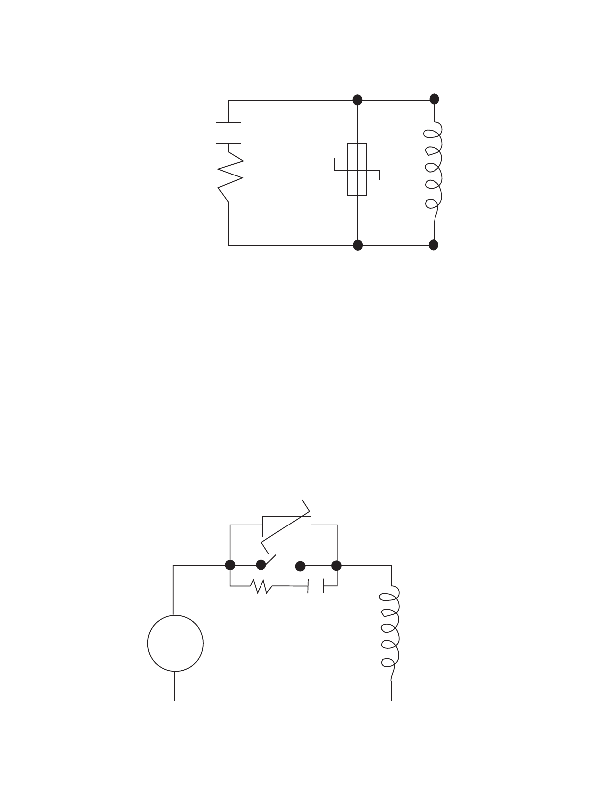
FIGURE 2-4
0.5
mfd
1000V
115V 1/4W
230V 1W
220
ohms
Inductive
Coil
Contacts - Arcing may occur across contacts when the contact opens and
closes. This results in electrical noise as well as damage to the contacts.
Connecting a RC network properly sized can eliminate this arc.
For circuits up to 3 amps, a combination of a 47 ohm resistor and 0.1 microfarad capacitor (1000 volts) is recommended. For circuits from 3 to 5
amps, connect 2 of these in parallel. See Figure 2-5, below.
FIGURE 2-5
AC
MOV
R C
Inductive
Coil
MIC 1462 Manual
8
Edition 1
Page 15

2.3.5 SENSOR PLACEMENT (THERMOCOUPLE OR RTD)
Two wire RTD's should be used only with lead lengths less than 10 feet.
If the temperature probe is to be subjected to corrosive or abrasive conditions, it should be protected by the appropriate thermowell. The probe
should be positioned to reflect true process temperature:
In liquid media - the most agitated area
In air - the best circulated area
9 MIC 1462 ManualEdition 1
Page 16

FIGURE 2-6
Rear Terminal Connections
END OF
PROGRAM
OUTPUT
+
INPUT
Linear (mA)
-
N/O
N/C
-
-
+
+
RTD
Linear (V/mV)
Thermocouple
Transmitter Power Supply
9
C
8
7
6
5
4
3
2
1
OUTPUT 3
-
Relay
N/C
SSR/DC
-
11
23 22
24
+
N/OC
+
MAINS (LINE)
L
N
B
A
COM
-
+
SUPPLY
24V 24V
-
AC DC
+
RS485
SERIAL
COMMS.
N/C
C
SSR/DC
N/O
Relay
OUTPUT 1
1210
13
14
15
16
17
18
19
20
21
+
SSR/DC
N/O
C
Relay
+
Transmitter Power Supply
Output 2
-
N/C
-
MIC 1462 Manual
10
Edition 1
Page 17

FIGURE 2-6A
RESET
RUN/HOLD
REMOTE INPUTS
X60 (FAST)
R0
R1
R2
C
33
32
31
30
29
28
27
26
25
34
#1
35
36
#2
37
38
#3
39
EVENT OUTPUTS
40
#4
41
42
11 MIC 1462 ManualEdition 1
Page 18

2.4 Input Connections
In general, all wiring connections are made to the instrument after it is installed. Avoid electrical shock. AC power wiring must not be connected to
the source distribution panel until all wiring connection procedures are
completed.
Caution: This equipment is designed for installation in an
enclosure which provide adequate protection against electric shock. Local regulations regarding electrical installation should be rigidly observed. Consideration should be
given to prevention of access to the power terminations by
unauthorized personnel. Power should be connected via a
two pole isolating switch (preferably situated near the
equipment) and a 1 A fuse, as shown in Figure 2-7.
FIGURE 2-7
Main Supply
The instrument will operate on 90-264V AC 50/60 Hz mains (line) supply.
The power consumption is approximately 4 VA. If the instrument has relay
outputs in which the contacts are to carry mains (line) voltage, it is recommended that the relay contact mains (line) supply should be switched and
fused in a similar manner but should be separate from the instrument
mains (line) supply.
MIC 1462 Manual
13
14
L
N
12
Line
Neutral
Edition 1
Page 19

FIGURE 2-7A
24V Nominal AC/DC Supply
The supply connection for the 24V AC/DC option of the instrument are as
shown below. Power should be connected via a two pole isolating switch
and a 315 mA slow -blow (anti-surge type T) fuse. With the 24V AC/DC
supply option fitted, these terminals will accept the following supply voltage
ranges:
24V (nominal) AC 50/60Hz - 20-50V
24V (nominal) DC - 22-65V
L
13
14
N
24V AC
50/60Hz
-
24V DC
+
FIGURE 2-8
Thermocouple (T/C) Input
Make the thermocouple connections as illustrated below. Connect the
positive leg of the thermocouple to terminal 2 and the negative leg to
terminal 3.
-
+
Thermocouple
FIGURE 2-9
RTD Input
Make RTD connections as illustrated below. For a three wire RTD, connect the resistive leg of the RTD to terminal 1 and the common legs to
terminals 2 and 3. For a two wire RTD, connect one leg to terminal 2 and
the other leg to terminal 3 as shown below. A jumper wire supplied by the
customer must be installed between terminals 2 and 3. (Continued on next
page)
3
2
13 MIC 1462 ManualEdition 1
Page 20

Input conditioning jumper must be positioned correctly (see Appendix B)
and Hardware Definition Code must be correct (see Appendix C).
3
2
RTD
1
FIGURE 2-10
Volt, mV Input
Make volt and millivolt connections as shown below. Terminal 2 is positive
and terminal 3 is negative. Input conditioning jumper must be positioned
correctly (see Appendix B) and Hardware Definition Code must be correct
(see Appendix C).
-
+
Linear (V/mV)
FIGURE 2-11
mADC Input
Make mADC connections as shown below. Terminal 4 is positive and terminal 1 is negative Input conditioning jumper must be positioned correctly
(see Appendix B) and Hardware Definition Code must be correct (see Appendix C).
+
3
2
1
4
3
MIC 1462 Manual
Linear (mA)
-
2
1
14
Edition 1
Page 21

FIGURE 2-12
Remote Digital Communications - RS485
Make digital communication connections as illustrated below.
16
17
18
B
A
COM
Output Connections 2.5
FIGURE 2-13
Relay Output 1 (Control Output 1)
Connections are made to Output 1 relay as illustrated below. The contacts
are rated at 2 amp resistive, 120/240 VAC .
19
N/C
20
21
FIGURE 2-14
SSR Driver Output 1 (Control Output 1)
Connections are made to Output 1 SSR Driver as illustrated below. The
solid state relay driver is a non-isolated 0-4 VDC nominal signal. Output
impedance is 250 ohms.
19
20
21
C
Relay
N/O
-
SSR
+
15 MIC 1462 ManualEdition 1
Page 22

FIGURE 2-15
mADC Output 1 (Control Output 1)
Make connections for DC Output 1 as illustrated below.
19
20
21
FIGURE 2-16
Relay Output 2 (Control Output 2 OR Alarm 2)
Connections are made to Output 2 relay as illustrated below. The contacts
are rated at 2 amp resistive, 120/240 VAC.
24 23 22
-
DC
+
N/O
FIGURE 2-17
SSR Driver Output 2 (Control Output 2 OR Alarm 2)
Connections are made to Output 2 SSR Driver as illustrated below. The
solid state relay driver is a non-isolated 0-4 VDC nominal signal. Output
impedance is 250 ohms.
24 23 22
+
C
Relay
SSR
N/C
-
MIC 1462 Manual
16
Edition 1
Page 23

FIGURE 2-18
mADC Output 2 (Control Output 2)
Make connections for DC Output 2 as illustrated below.
24 23 22
+
DC
FIGURE 2-19
Transmitter Power Supply Out 2
Make connections for 24V DC transmitter power supply as illustrated below
24 23 22
+
24VDC Transmitter Power
Supply
FIGURE 2-20
Relay Output 3 (Alarm 1)
Connections are made to Output 3 relay as illustrated below. The contacts
are rated at 2 amp resistive, 120/240 VAC.
-
-
Relay
N/OCN/C
10 11 12
17 MIC 1462 ManualEdition 1
Page 24

FIGURE 2-21
SSR Driver Output 3 (Alarm 1)
Connections are made to Output 3 SSR Driver as illustrated below. The
solid state relay driver is a non-isolated 0-4 VDC nominal signal. Output
impedance is 250 ohms.
SSR
-
10 11 12
FIGURE 2-22
mADC Output 3 (Recorder Output Only)
Make connections for DC output 3 as illustrated below.
DC
-
10 11 12
+
+
FIGURE 2-23
Transmitter Power Supply Out 3
Make connections for 24V DC transmitter power supply as illustrated below.
24VDC Transmitter Power
Supply
+
Edition 1
MIC 1462 Manual
-
10 11 12
18
Page 25

FIGURE 2-24
End of Program Output
Connections are made to End of Program Output as shown below. The
contacts are rated at 5 amp resistive, 120/240 VAC.
N/O
9
END OF
PROGRAM
C
8
OUTPUT
N/C
7
FIGURE 2-25
Event Outputs (optional)
If the Event Outputs have been specified and if the External Option parameter in Hardware Definition is set to either OUT of BOTH, Event Outputs
are available. Make connections as shown on top of next page. The contacts are rated at 5 amps, 120/240 VAC.
34
#1
35
36
37
38
39
40
41
42
#2
#3
EVENT OUTPUTS
#4
19 MIC 1462 ManualEdition 1
Page 26

FIGURE 2-26
Remote Program Outputs (optional)
If the Remote Program Control Inputs has been specified, make connections as shown. These inputs can be either TTL or switch contact, selectable in Hardware Definition. The following applies:
Terminals 31 (R2) to 33 (RO) provide a binary-coded input which is used to
select the program:
Digital Inputs=TTL Level Digital Inputs=Contacts (switches)
R0 R1 R2 Progran Select R0 R1 R2 Program Select
0 0 0 Program 1 Closed Open Open Program 1
1 0 0 Program 2 Open Closed Open Program 2
0 1 0 Program 3 Closed Closed Open Program 3
1 1 0 Program 4 Open Open Closed Program 4
0 0 1 Program 5 Closed Open Closed Program 5
1 0 1 Program 6 Open Closed Closed Program 6
0 1 1 Program 7 Closed Closed Closed Program 7
1 1 1 Program 8 Open Open Open Program 8
For the Program Control Inputs, the following convention has been
adopted: for TTL inputs OFF=logic 0, ON=logic 1; for contacts (switch)
inputs OFFG=open, ON=closed.
Terminal 30 is the Program Abort control. It is EDGE SENSITIVE; an OFFON transition at any time will cause an immediate Program Abort.
Terminal 29 provides the Remote Run/Hold Program control and has an
identical effect to that of the Run/Hold key on the front panel. An OFF-ON
transition will cause the currently selected program to be run (or to be resumed if it is currently held); AN ON-OFF transition will cause the currently
running program to be held. Powering up the instrument with this terminal
ON will not cause a program to run.
Terminal 28 provides the "x60" program time base selection. This terminal
is LEVEL SENSITIVE (ON=minutes/seconds, OFF=hours/minutes). When
the instrument is powered up, the initially powered time bese will be according to the level on this terminal at power-up.
NOTE: All remote selection/control functions except the Abort function have
MIC 1462 Manual
20
Edition 1
Page 27

precedence over the corresponding front panel controls. The "x60" func-
tion will also take precedence over any present x60 parameter settings.
33
R0
32
R1
31
R2
RESET
RUN/HOLD
30
29
REMOTE INPUTS
C
28
27
X60 (FAST)
Note: Only one remote connection shown for clarity.
FIGURE 2-27
Valve Motor Drive (VMD) Control Relay Outputs 1 & 2
The contacts are rated at 2A resistive at 120V (motor drive). Connections
are made as shown below.
19
20
N/C
C
Relay
Output 1
24 23 22
N/O
C
Relay
Output 2
N/C
21
N/O
NOTE: With VMD control, the controller is designed to switch on either
Output 1 or Output 2 (to open or close the valve). However, under fault
conditions, both Output 1 and Output 2 relays could be switched on simultaneously. For safety purposes, an interlock can be included which connects the supply to the motor via the "normally closed" relay contacts on
the Output 1 and Output 2 relays (see Figure 2-26)
21 MIC 1462 ManualEdition 1
Page 28

FIGURE 2-28
19
N/C
Motor
Supply
Close
Open
Common
24 23 22
N/O
"Close Valve" Relay
C
N/C
20
21
C
N/O
"Open
Valve"
Relay
MIC 1462 Manual
22
Edition 1
Page 29

Section 3 - Operation
3.1 POWER UP PROCEDURE
Verify all electrical connections have been properly made before applying
power to the instrument.
If the instrument is being powered for the first time, it may be desirable to
disconnect the controller output connections. The instrument will be into
control following the power up sequence and the output(s) may turn ON .
During Power up, a self-test procedure is initiated during which all LED
segments in the two front panel displays appear and all LED indicators are
ON . When the self-test procedure is complete, the instrument reverts to
normal operation.
Note: When power is first applied, a delay of approx. 3 seconds will be
seen before the displays light up.
3.2 KEYPAD OPERATION
Mode Key
MODE
Cycles through modes available in the instrument.
Scroll Key
Displays the next parameter in sequence (indicated by Message display).
Up Key
Increments displayed parameter value/cycles through options.
Down Key
Decrements displayed parameter value/cycles through options.
23 MIC 1462 ManualEdition 1
Page 30

PROF
PROF Key
Cycles through Program (profile) numbers.
RUN/HOLD
RUN/HOLD Key
Runs, holds or aborts current program (profile).
+
+
+
PROF
MODE
Jumps to next segment, when program is
running.
Selects/de-selects Manual Control
Sets a segment to Dwell when defining a
program.
MIC 1462 Manual
24
Edition 1
Page 31

3.3 INDICATORS
Control Status Indicators
AT - ON when Self-Tune is active; flashes when Pre-
AT
ALM - Flashes when any alarm is active.
ALM
OP1 - ON when primary control output is active.
OP1
OP2 - ON when secondary control output (if fitted) is
OP2
MAN - ON when Manual Control is selected.
MAN
Run Status Indicators
RUN - ON - Program running or (if HLD ON also) held
RUN
HLD - ON - Program held
HLD
x60 - OFF - timebase = hours/minutes
x60
Tune is active.
active.
Flashing - Program in Delayed state
Flashing - Program in Auto-Hold
ON - timebase = minutes/seconds
EV1
EV2
EV3
EV4
SET
PRG
Event Indicators
Each indicates the status (active or inactive) of a user-defined
event (OFF = inactive, ON = active)
Mode Indicators
SET - ON when any mode is entered; flashes when in
Controller Parameter Mode.
PRG - ON when Profile Set Mode is entered.
25 MIC 1462 ManualEdition 1
Page 32

3.4 DISPLAYS
UPPER DISPLAY
Process Variable value
LOWER DISPLAY
Setpoint value or value/setting
of parameter being viewed/edited.
MESSAGE DISPLAY
CURRENT RAMP STATE
= UP Ramp
= DOWN Ramp
PROGRAM NUMBER
Number of currentlyselected program
SEGMENT NUMBER
Number of current segment
3.5 ALARM STATUS INDICATION
When any alarm is active, the ALM indicator will flash. To view the main
status in the Message Display, press the SCROLL key until a display appears in the form:
BOTH ON = Dwell
Both flashing = In Manual Control while
program is running
Appears only if Alarm 1 is active
Appears only if Alarm 2 is active
Appears only if the Loop Alarm is active
MIC 1462 Manual
26
Edition 1
Page 33

3.6 VIEWING PROGRAM AND CONTROLLER PARAMETERS
In Base Mode (i.e. with no profile currently running or held), pressing the
SCROLL key will cause the instrument to display various information. The
operator may view and change the setpoint, view the units the instrument is
using, weather the outputs are on or off, the alarm status, the present time
and day (if the real time clock is fitted), and the percent output of the control
instrument if operating in Manual Mode.
NOTE: If the SCROLL key is held for longer than two seconds, the instrument will automatically scroll through the displays.
BASE
SETPOINT
(Units)
AlSt
OUTPUTS
time
Day
MODE
3.7 ADJUSTING THE CONTROLLER SETPOINT
With the Setpoint Programmer in Base Mode (i.e. with the RUN, HLD, SET,
MAN and PRG indicators OFF), the two main displays will show the pro-
cess variable value (upper display) and the setpoint value (lower display Read Only). To change the setpoint value:
1. Press the SCROLL key, the Message Area will display:
2. If Setpoint has been enabled in the Enable mode, use the UP and
DOWN keys to change the setpoint value (in the lower display) as required.
3. When the setpoint value is set as desired, press the SCROLL key
again to view other Base mode parameters.
27 MIC 1462 ManualEdition 1
Page 34

3.8 VIEWING THE INPUT UNITS
To see what type of input the control is using press the SCROLL key until
the Units display is shown. The Units display shows the temperature scale
for thermocouple and RTD inputs <DEGF> or <DEGC> or unspecified
engineering UNITS for other input types. This display can be deactivated,
if desired.
OVER-RANGE/UNDER-RANGE DISPLAY
If the process variable attains a value higher than the input scale maximum
limit, the upper display will show:
If the process variable attains a value lower than the input scale minimum,
the upper display will show:
If a break is detected in the sensor circuit, the upper display will show:
If the CJC facility in the Configuration Mode is disabled, the initial display in
Operator Mode will show:
flashing in the lower display.
MIC 1462 Manual
28
Edition 1
Page 35

3.9 BASE MODE AND OFF MODE OUTPUTS
The Base Mode allows for the process and event outputs to be turned on or
off. When all outputs are off, the Base Mode becomes Off Mode. In Base
Mode the process output is adjusted by the controller based on the process
input and setpoint. The event outputs for the Base Mode are set in the
Configuration Mode. To view the present status of the outputs, press the
SCROLL key until OUTPUTS is displayed in the message display. Use the
UP and DOWN keys to turn the outputs ON or OFF (toggle between Base
Mode and Off Mode).
3.10 VIEWING THE TIME AND DAY
If the real time clock option is fitted, the operator may view the present time
and day. Press the SCROLL key until HH:MM Tim is displayed. This is the
present time of day in hours and minutes. Press the SCROLL key again
and Day: XXX is displayed with XXX being an abbreviation for the present
day of the week. If TIME BAD is displayed, the time and day must be set
in the Profile Mode (see sec. 6)
3.11 MANUAL CONTROL
In any mode except Configuration Mode, the operator may select manual
control of the process by simultaneously pressing the SCROLL and MODE
keys, provided Manual Mode is enabled in Controller Define Mode. The
instrument will then enter Base Mode or (if a program is currently running)
Program Run Mode with the program held. The Message Display will
show:
The lower Main Display will show the power output value, which may then
be adjusted using the UP and DOWN keys and the MAN indicator will be lit.
While manual control is being used, the power output display is included in
the displays available in Base Mode and Program Run Mode.
29 MIC 1462 ManualEdition 1
Page 36

To cancel manual control, press the SCROLL and MODE keys simultaneously, wereupon the power out value display and the Power message
display will disappear and the Setpoint Controller will remain in whatever
mode prevailed when manual control was cancelled (if this is Program Run
Mode, the currently-running program will be resumed from the point at
which it was held).
3.12 USING THE PRE-TUNE FACILITY
The Pre-Tune facility is used to set the instrument's PID control parameters
to values which are approximately correct in order to provide a base from
which the Self-Tune facility may subsequently optimize tuning. Pre-Tune
may be activated as follows:
1. With the instrument in Base mode (with the RUN and HLD indicators
OFF), press the MODE key until the Message Display shows:
and the lower Main Display shows:
2. Press the UP key to change the lower Main Display to:
indicating that the Pre-Tune facility is now activated. The AT indicator
will flash.
NOTES:
1. If the process variable is within 5% of the input span from the
setpoint, the Pre-Tune facility cannot be activated and any attempt
to do so will have no effect.
2. Since the Pre-Tune facility is a single-shot operation, it will automatically de-activate itself once the operation is complete.
MIC 1462 Manual
30
Edition 1
Page 37

To de-activate the Pre-Tune facility manually (with the instrument in
Base Mode), press the MODE key to obtain the same Message Displays
above; then press the DOWN key simultaneously to change the lower
Main display from ON to OFF.
3.13 USING THE SELF-TUNE FACILITY
The Self-Tune facility is used to optimize tuning while the Controller part of
the instrument is operating. Self Tune may be activated as follows:
1. With the instrument in Base Mode (with RUN and HLD indicators
OFF), press the MODE key until the Message Display shows:
and the lower Main Display shows:
2. Press the UP key to change the lower Main Display to:
indicating that the Self-Tune facility is now activated. The AT indicator is
on continuously.
To de-activate the Self-Tune facility, press the MODE key to obtain the
same Message Display as above; then press the DOWN key to change the
lower Main Display from ON to OFF.
31 MIC 1462 ManualEdition 1
Page 38

Section 4 - Configuration
4.1 ENTRY INTO CONFIGURATION MODE
To enter Configuration Mode:
1. Press the MODE Key until Conf Par appears in the message display.
2. Press the SCROLL Key to enter the Configuration Mode
The instrument will then enter Configuration Mode, whereupon the main
display will initially be of the form:
showing the current input code selected, and the Message Display will
show:
The user may then step through the Configuration Mode parameters using
the SCROLL key. For each parameter, the Message Display will show a
legend identifying that parameter and the lower main display will show the
current setting of that parameter. The setting may be adjusted using the
UP/DOWN keys. As soon as the setting is changed, the lower main display
will flash, indicating that the new setting has yet to be confirmed. When the
setting is as required, it may be confirmed by pressing the MODE key,
whereupon the upper display will stop flashing.
NOTE: Changes to certain Configuration Mode parameters (i.e.
input range, output use and type) will cause other mode parameters to be automatically set to their defauly values. Items affect
include Tune Mode, and Pretune and Auto Tune Facilities. Until the
Tune Mode setting have been verified by changing at least one
paraneter, the upper main display will show decimal points to indicate that the values are in their default condition.
Changes to Configuration Mode parameters will not be accepted
until they have been verified with the PROF key.
MIC 1462 Manual
32
Edition 1
Page 39

4.2 HARDWARE DEFINITION CODE
This parameter is a special facility in Configuration Mode, which is used to
specify the hardware fitted (input type, output types, etc); this must be compatible with the hardware actually fitted. It can be accessed, with the instrument in Configuration Mode, by simultaneously pressing the DOWN
and SCROLL keys. The Message Display will then show:
and lower main display will be of the form:
Input Type
1 RTD/Linear (mV)
2 Thermocouple
3 Linear DC (mA)
4 Linear DC (V)
Output 1 Type
1 Relay Output
2 SSR Output
3 DC Output (0-10V)
4 DC Output (0-20mA)
5 DC Output (0-5V)
7 DC Output (4-20mA)
Output 3 Type
0 None
1 Relay Output (Alarm Output Only)
2 SSR Output (Alarm Output Only)
3 DC Output 0-10V (Recorder Output Only)
4 DC Output 0-20mA (Recorder Output Only)
5 DC Output 0-5V (Recorder Output Only)
7 DC Output 4-20mA (Recorder Output Only)
Output 2 Type
0 None
1 Relay Output (Control or Alarm Output)
2 SSR Output (Control or Alarm Output)
3 DC Output 0-10V (Control Output Only)
4 DC Output 0-20mA (Control Output Only)
5 DC Output 0-5V (Control Output Only)
7 DC Output 4-20mA (Control Output Only)
33 MIC 1462 ManualEdition 1
Page 40

The displayed code may be incremented/decremented using the UP/
DOWN keys as required. The maximum setting available for this code is
4777. For example, the code for a thermocouple input, 4-20mA DC primary
output (Output 1) and relay Output 3 would be 2701. When the code is first
altered, the code display will flash, until the desired value is displayed and
confirmed by pressing the MODE key.
NOTE: It is essential that this code is changed promptly whenever
there is a change to the instrument's hardware configuration
(change of input/output type, alarm/recorder output added/removed
etc.). The instrument software depends upon this code to operate
correctly.
Hardware Definitions may be viewed as Read Only displays in Base Mode
by pressing the SCROLL and DOWN keys simultaneously.
While the Hardware Definition Code is displayed, pressing the SCROLL
key will cause the Message Display to change to:
and the lower main display to change to one of:
No option PCB
fitted
Digital Input
Option PCB
fitted
Both Option
PCBs fitted
Event Output
Option PCB
fitted
The desired setting can be achieved using the UP/DOWN keys.
MIC 1462 Manual
34
Edition 1
Page 41

Press the SCROLL key to change the Message Display to:
and the lower main display to one of:
RS485
Communications
Option PCB not
fitted
RS485
Communications
Option PCB fitted -
Programmer acting as
slave device
Option PCB fitted -
Programmer acting as
RS485
Communications
master device
The desired setting can be achieved using the UP/DOWN keys.
Pressing the SCROLL key again will display Inputs in the Message Display.
Press the UP and DOWN keys to select from contact (cont) and low voltage (ttl) type inputs.
Pressing the SCROLL key again will display the desired function of the
remote input wired to terminal 28 (see Sec. 2). Press the UP and DOWN
keys to select from X60 timebase (60) or jump to next segment (SEGJ).
This input can be used to remotely control the appropriate function in the
Program Run Mode.
To exit from the Hardware Definition Code facility, press the DOWN and
SCROLL keys simultaneously (which will cause a return to the normal Configuration Mode). Alternatively, either of the methods of exit from Configuration Mode may be used here.
35 MIC 1462 ManualEdition 1
Page 42

4.3 CONFIGURATION MODE PARAMETERS
The Configuration Mode parameters are presented for view/edit in the following sequence:
MESSAGE AVAILABLE
STEP DESCRIPTION DISPLAY FUNCTION SETTING
1 Primary Input Input Code display- See App. A
Range
5
ed defines
input type/
range (see
App. A)
2 Control Action Control Specifies dir - Direct
control Acting
action of rEV- Reverse
Output 1
1
Acting
*Mdr-Motor
Drive
Reverse
* Not available if Output 1 AND Output 2
are Not Relay Outputs
*Mdd-Motor
Drive
Direct
3 Output 2 Usage Out2 Use Specifies out2-Control
use of Output
Output 2
2
A2_d-Alarm 1
(direct)
A2_r-Alarm 2
(reverse)
NOTE: This parameter not available if
Control Action is set to Mdr or Mdd-Output
2 automatically used as control output
Or_d-Alarm 1
OR 2
(direct)
Or_r-Alarm 1
OR 2
(reverse)
Ad_d-Alarm 1
AND 2
(direct)
Ad_r-Alarm 1
AND 2
(reverse)
MIC 1462 Manual
36
Edition 1
Page 43

MESSAGE AVAILABLE
STEP DESCRIPTION DISPLAY FUNCTION SETTINGS
LP_d-Loop
Alarm
(direct)
LP_r-Loop
Alarm
(reverse)
4 Output 3 Useage Out3 Use Specifies Al_d-Alarm 1
use of (direct)
Output 3
3
Al_r-Alarm 1
(reverse)
Or_d-Alarm 1
OR 2
(direct)
Or_r-Alarm 1
OR 2
(reverse)
Ad_d-Alarm 1
AND 2
(direct)
Ad_r-Alarm 1
AND 2
(reverse)
LP_d-Loop
Alarm
(direct)
LP_r-Loop
Alarm
(reverse)
rEcS-Rcdr
Output
(SP)
rEcP-Rcdr
Output
(PV)
37 MIC 1462 ManualEdition 1
Page 44

MESSAGE AVAILABLE
STEP DESCRIPTION DISPLAY FUNCTION SETTINGS
5 Segment Mode Seg Mode Defines para- ti- Time
meter used to rA-Ramp Rate
specify duration
of each segment
(along with final
SP value)
6 Baud Rate
7 Protocol
8 Address
6
6,7
6
Baud Rate Selects Baud Numeric
Rate for RS485 value: 1200,
Comms. 2400, 4800 or
9600
Protocol Select protocol Mbn-Modbus,
and parity for no parity
RS-485 Comms Mbo-Modbus,
odd parity
Mbe-Modbus,
even parity
WES-ASCII
Address Selects RS485 Numeric
comm. address value in range
1-32
9 CJC4 Enable/ CJC Enables/ EnAb-enabled
Disabled disables cold diSA-disabled
junction comp.
10 Events10 Events Set event status Binary with
in Base Mode LSD=Event 1
0100=Event3
on, all other
events off
MIC 1462 Manual
38
Edition 1
Page 45

MESSAGE AVAILABLE
STEP DESCRIPTION DISPLAY FUNCTION SETTINGS
11 Scale Range DecPos For Linear 0 XXXX
Decimal Point
9
Inputs, defines 1 XXX.XDefault
decimal point 2 XX.XX
position 3 X.XXX
12 Scale Range EngU UP For linear inputs -1999 to 9999
Maximum
9
,defines the (decimal point
scaled input as defined by
value when the Scale Range
process variable Decimal Point
input is at its parameter)
maximum value
13 Scale Range EngU LO For linear inputs -1999 to 9999
Minimum
9
,defines the (decimal point
scaled input as defined by
value when the Scale Range
process variable Decimal Point
input is at its parameter)
minimum value
14 Setpoint High SP High The Maximum Current set-
8
Limit
limit for setpoint point value to
adjustment. input range
Should be set to max.
a value which
prevents setpoint values
causing damage
to the process
39 MIC 1462 ManualEdition 1
Page 46

MESSAGE AVAILABLE
STEP DESCRIPTION DISPLAY FUNCTION SETTINGS
15 Setpoint Low SP Low The Minimum Current set-
8
Limit
limit for setpoint point value to
adjustment. input range
Should be set to min.
a value which
prevents setpoint values
causing damage
to the process
16 Input Filter Filter Defines time 0.0 seconds
Time Constant constant for (filter OFF)
input filter (re- to 100.0 sec.
moves extra- in 0.5 increneous impulse ments.
from the
process variable
input.)
17 Output Power Out PL Determines max 0 to 100 (%)
Limit output setting
instrument will
provide
18 Engineering Units3Units Sets units to be Unit
displayed in CEnt
base mode FAHr
19 End of Program EOprelay Sets action of End=relay
relay active at end
of profile
run=relay
active during
profile
Default=End
For Notes on Configuration Mode Parameters, see next page.
MIC 1462 Manual
40
Edition 1
Page 47

Notes on Configuration Mode Parameters
1. If the secondary output is chosen as Output 2 (COOL) control output, its
action is always the compliment of the action of Output 1.
2. The default setting for Output 2 Usage is Alarm 2 hardware output,
direct-acting (if relay/SSR output) or Output 2 - COOL (if DC output).
3. The default setting for Output 3 Usage is Alarm 1 hardware output,
direct-acting (if relay/SSR output) or Process Variable Recorder Output
(if DC output)
4. This parameter does not appear in the sequence if the input type
selected is not thermocouple. If the CJC is disabled, the initial display in
Operator Mode will show horizontal bars flashing in the lower display.
5. The primary input default setting is dependent upon the hardware fitted,
as indicated in the Hardware Definition Code.
6. These parameters do not appear if the Hardware Definition Comms
parameters is set to nonE.
7. This parameter does not appear if the Programmer communications
option is set to operate in Master mode.
8. Internal software prevents (a) the Setpoint High Limit being given a
value less than any setpoint value contained in currently-resident pro grams, and (b) the Setpoint Low Limit being given a value greater than
any setpoint value contained in currently-resident programs.
9. These parameters are applicable only if a linear input is fitted.
10. These parameters do not appear if features are not fitted.
11. When X60 in Profile Set = OFF, Time = hours/minutes and
Ramp Rate = LSD/hour
When X60 in Profile Set = ON, Time = minutes/seconds and
Ramp Rate - LSD/minute
4.4 EXIT FROM CONFIGURATION MODE
To leave Configuration Mode, depress and hold the MODE key for five
seconds.
The exit is made via the power-up self-test routines which includes a lamp
test.
41 MIC 1462 ManualEdition 1
Page 48

Section 5 - Defining The Tune Parameters
Entry can be made into this mode from Program Define Mode, Program
Run Mode or Base Mode.
To enter from Base Mode or Program Run Mode:
1. Press the MODE key until the Message Display will show:
2. Press the SCROLL key.
The instrument is now in the Tune Mode.
Upon entry into the Tune Mode, the SET indicator will then come ON and
the first of the Tune parameters (Input Correction) will be presented for
editing/viewing. Using the SCROLL key, step through the sequence of
Tune parameters, editing as required (using the UP/DOWN keys).
MIC 1462 Manual
42
Edition 1
 Loading...