

Page 1

MIC 1460
1/4 DIN SETPOINT PROGRAMMER
OPERATORS MANUAL
FORM 3707
EDITION 1 © MAY 1996
PRICE $10.00
CIRCULAR CHART RECORDERS • STRIP CHART RECORDERS • DATA ACQUISITION SYSTEMS
DATALOGGERS • ANALOG AND MICROBASED CONTROLLERS
MECHANICAL RECORDERS AND CONTROLLERS
PARTLOW CORPORATION • 2 CAMPION ROAD • NEW HARTFORD, NY 13413 USA
1-800-866-6659 • 315-797-2222 • FAX 315-797-0403
Page 2

Information in this installation, wiring, and operation manual is subject to change
without notice. One manual is provided with each instrument at the time of shipment. Extra copies are available at the price published on the front cover.
Copyright © May 1996, The Partlow Corporation, all rights reserved. No part of
this publication may be reproduced, transmitted, transcribed or stored in a retrieval
system, or translated into any language in any form by any means without the
written permission of the Partlow Corporation.
This is the First Edition of the MIC 1460 manual. It was written and produced
entirely on a desk-top-publishing system. Disk versions are available by written
request to the Partlow Publications Department.
We are glad you decided to open this manual. It is written so that you can take full
advantage of the features of your new MIC 1460 setpoint programmer .
NOTE:
It is strongly recommended that Partlow equipped
applications incorporate a high or low limit protective device
which will shut down the equipment at a preset process
condition in order to preclude possible damage to property
or products.
Page 3

Table of Contents
Section 1 - General Page
1.1 Product Description 1
Section 2 - Installation & Wiring
2.1 Unpacking Procedure 3
2.2 Panel Mounting 3
2.3 Wiring Guidelines 5
2.4 Input Connections 12
2.5 Output Connections 15
Section 3 - Operation
3.1 Power-up Procedure 20
3.2 Keypad Operation 20
3.3 Indicators 22
3.4 Displays 23
3.5 Alarm Status Indication 23
3.6 Viewing Program and Controller Parameters 24
3.7 Adjusting the Setpoint 24
3.8 Manual Control 25
3.9 Using the Pre-Tune Facility 25
3.10 Using the Self-Tune Facility 26
Section 4 - Configuration
4.1 Entry into Configuration 28
4.2 Hardware Definition Mode 29
4.3 Configuration Mode Parameters 31
4.4 Alarm Inhibit Facility 35
4.5 Exit from Configuration Mode 35
Section 5 - Controller Define Mode
5.1 Controller Parameters 37
5.2 Base Mode Displays 52
5.3 Loop Alarm and Loop Alarm Time 52
5.4 Exiting Controller Define Mode 53
MIC 1460 ManualEdition 1 i
Page 4

Section 6 - Program Define Mode
6.1 Entry into Program Define 54
6.2 Paramters Common to All Programs 55
6.3 Parameters which apply to a Specific Program 57
6.4 Parameters in any/each Segment 61
6.5 Using Join, Repeat, and End Segments 64
6.6 Basic Rules to Remember 66
6.7 Exiting Program Define Mode 66
Section 7 - Programs
7.1 Selecting and Running a Program 67
7.2 Changing Timebase 67
7.3 Holding Manually 67
7.4 Jumping to Next Segment 68
7.5 Viewing Program Status 68
7.6 Aborting a Program 69
7.7 End of Progam Indication 69
7.8 Viewing Program/Control Parameters 70
Appendices
A - Input Range Codes 71
B - Board Layout - Jumper positioning 73
Figure B-1 PCB Positions 73
Figure B-2 Output 2/Output 3 Removal 74
Figure B-3 CPU PWA 75
Figure B-4 PSU PWA with Relay or SSR Out.1 76
Figure B-5 PSU PWA with DC Output 1 77
Figure B-6 Option PWA DC Output 2/Output 3 78
C - Specifications 79
D - Model Number Hardware Matrix 87
E - Software Reference Sheet 88
MIC 1460 Manual Edition 1ii
Page 5

Figures
Figure 1-1 Front Panel 2
Figure 2-1 Panel Cut-Out Dimensions 3
Figure 2-2 Main Dimensions 4
Figure 2-3 Panel Mounting the controller 5
Figure 2-4 Noise Suppression 8
Figure 2-5 Noise Suppression 8
Figure 2-6 Rear Terminal Connections 10
Figure 2-6A Rear Terminal Connections 11
Figure 2-7 Main Supply 12
Figure 2-7A 24V Nominal AC/DC Supply 13
Figure 2-8 Thermocouple (T/C) Input 13
Figure 2-9 RTD Input 14
Figure 2-10 Volt, mV Input 14
Figure 2-11 mA DC Input 14
Figure 2-12 Remote Digital Communications 15
Figure 2-13 Relay Output 1 15
Figure 2-14 SSR Driver Output 1 15
Figure 2-15 mADC Output 1 16
Figure 2-16 Relay Output 2 16
Figure 2-17 SSR Driver Output 2 16
Figure 2-18 mADC Output 2 17
Figure 2-19 Relay Output 3 17
Figure 2-20 SSR Driver Output 3 17
Figure 2-21 mADC Output 3 18
Figure 2-22 End of Program Output 18
Figure 2-23 Event Outputs 18
Figure 2-24 Remote Program Output 19
Figure 5-1 Proportional Band and Deadband/Overlap 48
Figure 5-2 Alarm Operation 49
Figure 5-3 Alarm Hysteresis Operation 51
Figure 6-1 Auto Hold Operation 60
MIC 1460 ManualEdition 1 iii
Page 6

MIC 1460 Manual Edition 1iv
Page 7

Section 1 - General
1.1 PRODUCT DESCRIPTION
This instrument is a powerful, easy-to-use 1/4 DIN setpoint programmer
with full PID control capability (complete with Self-Tune and Pre-T une facilities).
Its standard features include:
• Up to eight programs of up to 16 free-format (e.i. dwell, ramp, join, or
end) segments each.
• Facility to join programs to one another in any sequence (maximum
program length 121 segments)
• User can change currently-running program segment.
• Delayed Start of Program facility
• End of Program relay output
• Universal input-thermocouple, RTD (PT100) or DC linear user-selectable.
• Universal power supply (90 -264V AC 50/60 Hz)
• Configurable from front panel
• Comprehensive front panel displays
• Front panel sealing to NEMA 4 standard
• Behind-panel depth only 100mm (3.94 inchs)
Optional features include:
• Remote control and selection of program (plug-in option)
• Up to four Event relay outputs (plug-in option)
• Second control output
• Recorder output (setpoint or process variable)
• RS-485 serial communications
• User-definable program tag names
• Support software (Off-line Configurator, On-line Graphic Program
Editor) - operates via RS-485 communications link.
MIC 1460 ManualEdition 1 1
Page 8
The Setpoint Programmer has four operating modes:
Base Mode: Day to day PID control operations with no program running.
In this mode, a program may be selected to run.
Program Run Mode: A selected program is running, held or waiting for a
pre-defined delay before starting. In this mode, the operator can view
status and program information.
Program Define Mode:* Used to view/create/edit programs. this mode
is entered either from Base Mode (selected program may be edited/
created) or from Program Run Mode (currently-running program may be
edited).
Controller Define Mode:** Used to define the controller characteristics.
* Entry via Lock Code; also optional Program Lock prevents changing of
program definitions while a program is running.
** Enry via a Lock Code.
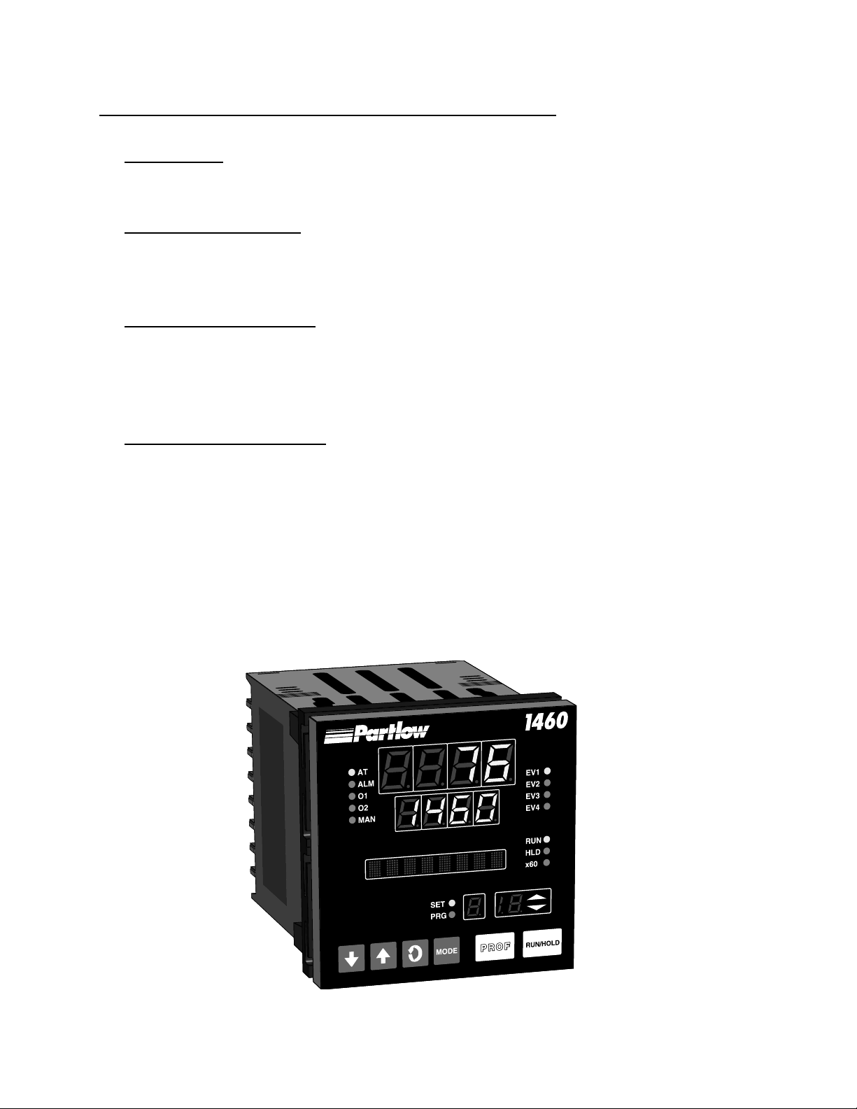
FIGURE 1-1
Front Panel
MIC 1460 Manual Edition 12
Page 9

Section 2 - Installation & Wiring
2.1 UNPACKING PROCEDURE
1. Remove the instrument from its packing. The instrument is supplied
with a panel gasket and push-fit strap. Retain the packing for future use,
should it be necessary to transport the instrument to a different site or
return it to the factory for repair/testing.
2. Examine the delivered items for damage or deficiencies. If any is
found, notify the carrier immediately. Check that the model number
shown on the label affixed to the instrument housing corresponds to that
ordered (see Appendix D).
2.2 PANEL-MOUNTING THE SETPOINT PROGRAMMER
The panel on which the instrument is to be mounted must be rigid and may
be up to 6.0 mm (.25 inches ) thick. The cutout required for a single instrument is shown in Figure 2-1.
FIGURE 2-1
Cut-Out Dimensions
92 mm +0.5 - 0.00
(3.62”+.020 - .000)
PANEL
CUTOUT
SIZE
92 mm + 0.5 - 0.0
(3.62” + .020 - .000)
MIC 1460 ManualEdition 1 3
Page 10
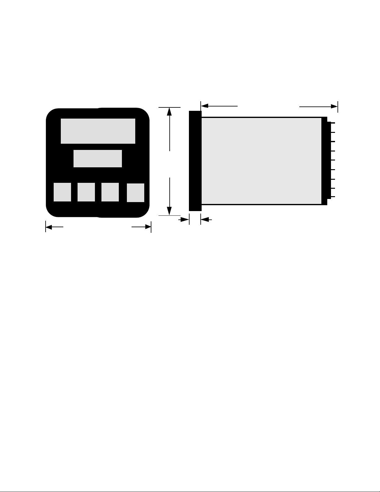
The main dimensions of the instrument are shown below.
FIGURE 2-2
Main Dimensions
100 mm (3.94 in.)
96 mm
(3.78 in)
Side View
96 mm
(3.78 in.)
Max. Panel Thickness 6.0mm (.25 inches)
10 mm (0.39 in.)
To panel-mount the instrument:
1. Insert the rear of the instrument housing through the cutout (from the
front of the mounting panel) and hold the instrument lightly in position
against the panel. Ensure that the panel gasket is not distorted and that
the instrument is positioned squarely against the mounting panel. Apply
pressure to the front panel bezel only.
Caution: Do not remove the panel gasket, as this may result
in inadequate clamping of the instrument in the panel.
2. Slide the fixing strap in place (Figure 2-3) and push it forward until it
is firmly in contact with the rear face of the mounting panel (the tongues
on the strap should have engaged in matching rachet positions on the
instrument housing and the fixing strap springs should be pushing firmly
against the mounting panel rear face).
MIC 1460 Manual Edition 14
Page 11
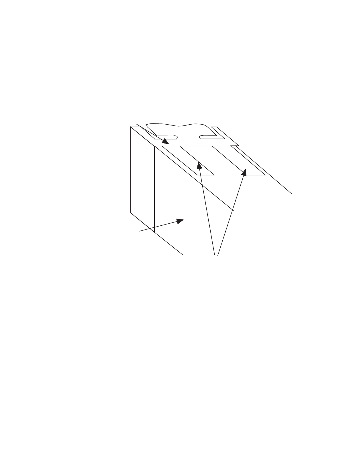
Once the instrument is installed in its mounting panel, it may be subsequently removed from its housing, if necessary, as described in Appendix
B.
FIGURE 2-3
Panel-Mounting the Instrument
Mounting Clamp
Controller Housing
Tongues on mounting clamp engage in
ratchet slots on controller housing
2.3 PREPARATION FOR WIRING
Electrical noise is a phenomenon typical of industrial environments. The
following are guidelines that must be followed to minimize the effect of
noise upon any instrumentation.
2.3.1 INST ALLATION CONSIDERA TIONS
Listed below are some of the common sources of electrical noise in the
industrial environment:
• Ignition T ransformers
• Arc Welders
• Mechanical contact relay(s)
• Solenoids
MIC 1460 ManualEdition 1 5
Page 12

Before using any instrument near the device listed, the instructions below
should be followed:
1. If the instrument is to be mounted in the same panel as any of the
listed devices, separate them by the largest distance possible. For maximum electrical noise reduction, the noise generating devices should be
mounted in a separate enclosure.
2. If possible, eliminate mechanical contact relay(s) and replace with
solid state relays. If a mechanical relay being powered by an instrument
output device cannot be replaced, a solid state relay can be used to
isolate the instrument.
3. A separate isolation transformer to feed only instrumentation should
be considered. The transformer can isolate the instrument from noise
found on the AC power input.
4. If the instrument is being installed on existing equipment, the wiring in
the area should be checked to insure that good wiring practices have
been followed.
2.3.2 AC POWER WIRING
Neutral (For 1 15 VAC)
It is good practice to assure that the AC neutral is at or near ground potential. To verify this, a voltmeter check between neutral and ground should be
done. On the AC range, the reading should not be more than 50 millivolts.
If it is greater than this amount, the secondary of this AC transformer supplying the instrument should be checked by an electrician. A proper neutral
will help ensure maximum performance from the instrument.
2.3.3 WIRE ISOLA TION
Four voltage levels of input and output wiring may be used with the unit:
• Analog input or output (i.e. thermocouple, R TD, VDC, mVDC, or
mADC)
• SPDT Relays
• SSR driver outputs
• AC power
MIC 1460 Manual Edition 16
Page 13

The only wires that should run together are those of the same category. If
they need to be run parallel with any of the other lines, maintain a minimum
6 inch space between wires. If wires must cross each other , do so at 90
degrees. This will minimize the contact with each other and reduces "cross
talk". "Cross Talk" is due to the EMF (Electro Magnetic Flux) emitted by a
wire as current passes through it. This EMF can be picked up by other
wires running in the same bundle or conduit.
In applications where a High Voltage Transformer is used (i.e. ignition systems) the secondary of the transformer should be isolated from all other
cables.
This instrument has been designed to operate in noisy environments, however , in some cases even with proper wiring it may be necessary to suppress the noise at the source.
2.3.4 USE OF SHIELDED CABLE
Shielded cable helps eliminate electrical noise being induced on the wires.
All analog signals should be run with shielded cable. Connection lead
length should be kept as short as possible, keeping the wires protected by
the shielding. The shield should be grounded at one end only. The preferred grounding location is the sensor, transmitter, or transducer .
2.3.5 NOISE SUPPRESSION AT THE SOURCE
Usually when good wiring practices are followed no further noise protection
is necessary. Sometimes in severe electrical environments, the amount of
noise is so great that it has to be suppressed at the source. Many manufacturers of relays, contactors, etc. supply "surge suppressors" which
mount on the noise source.
For those devices that do not have surge suppressors supplied. RC (resistance-capacitance) networks and/or MOV (metal oxide varistors) may be
added.
Inductive Coils - MOV's are recommended for transient suppression in
inductive coils connected in parallel and as close as possible to the coil.
See Figure 2-4. Additional protection may be provided by adding an RC
network across the MOV.
MIC 1460 ManualEdition 1 7
Page 14
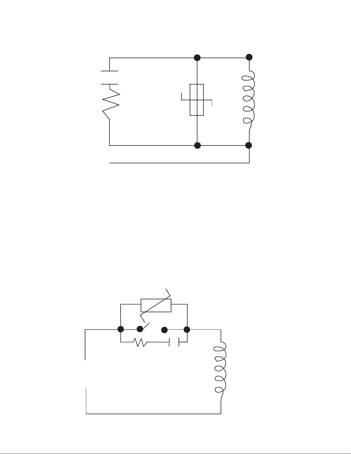
FIGURE 2-4
0.5
mfd
1000V
220
ohms
115V 1/4W
230V 1W
Coil
Contacts - Arcing may occur across contacts when the contact opens and
closes. This results in electrical noise as well as damage to the contacts.
Connecting a RC network properly sized can eliminate this arc.
For circuits up to 3 amps, a combination of a 47 ohm resistor and 0.1 microfarad capacitor (1000 volts) is recommended. For circuits from 3 to 5
amps, connect 2 of these in parallel. See Figure 2-5, below.
FIGURE 2-5
MOV
R C
Inductive
Coil
MIC 1460 Manual Edition 18
Page 15

2.3.5 SENSOR PLACEMENT (THERMOCOUPLE OR RTD)
Two wire RTD's should be used only with lead lengths less than 10 feet.
If the temperature probe is to be subjected to corrosive or abrasive condi-
tions, it should be protected by the appropriate thermowell. The probe
should be positioned to reflect true process temperature:
In liquid media - the most agitated area
In air - the best circulated area
MIC 1460 ManualEdition 1 9
Page 16
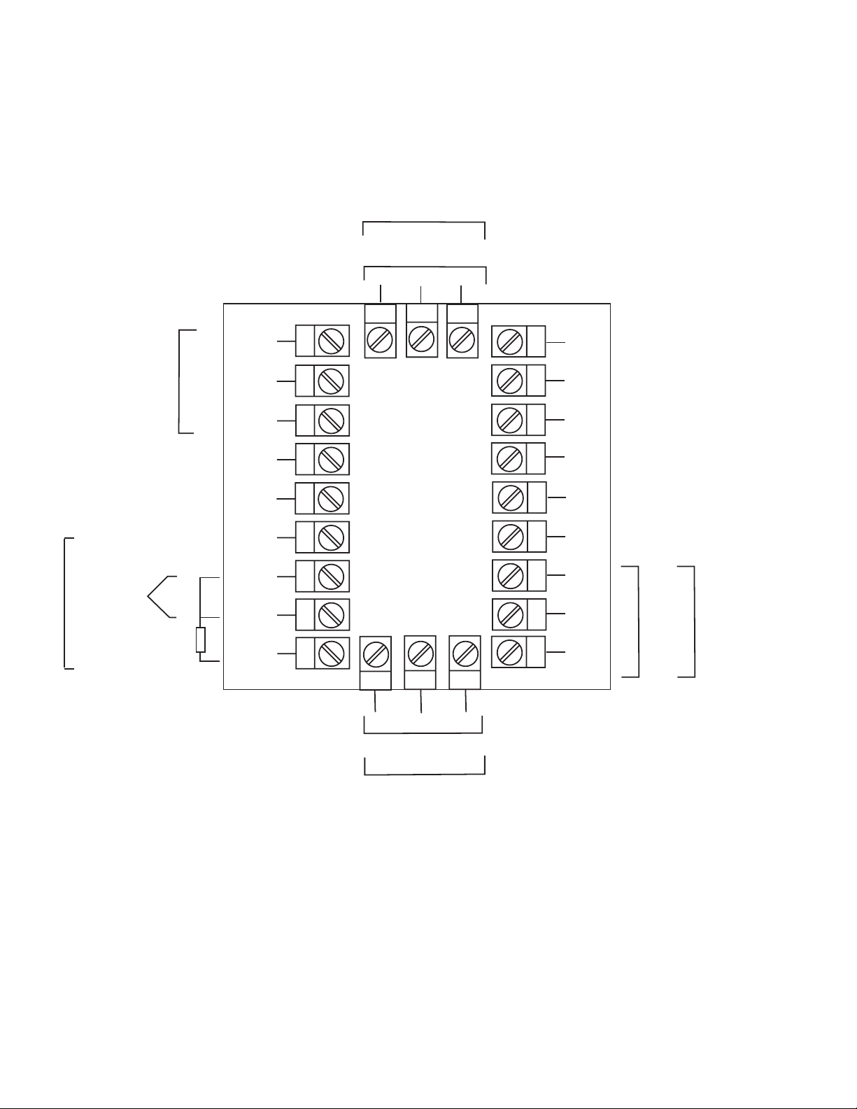
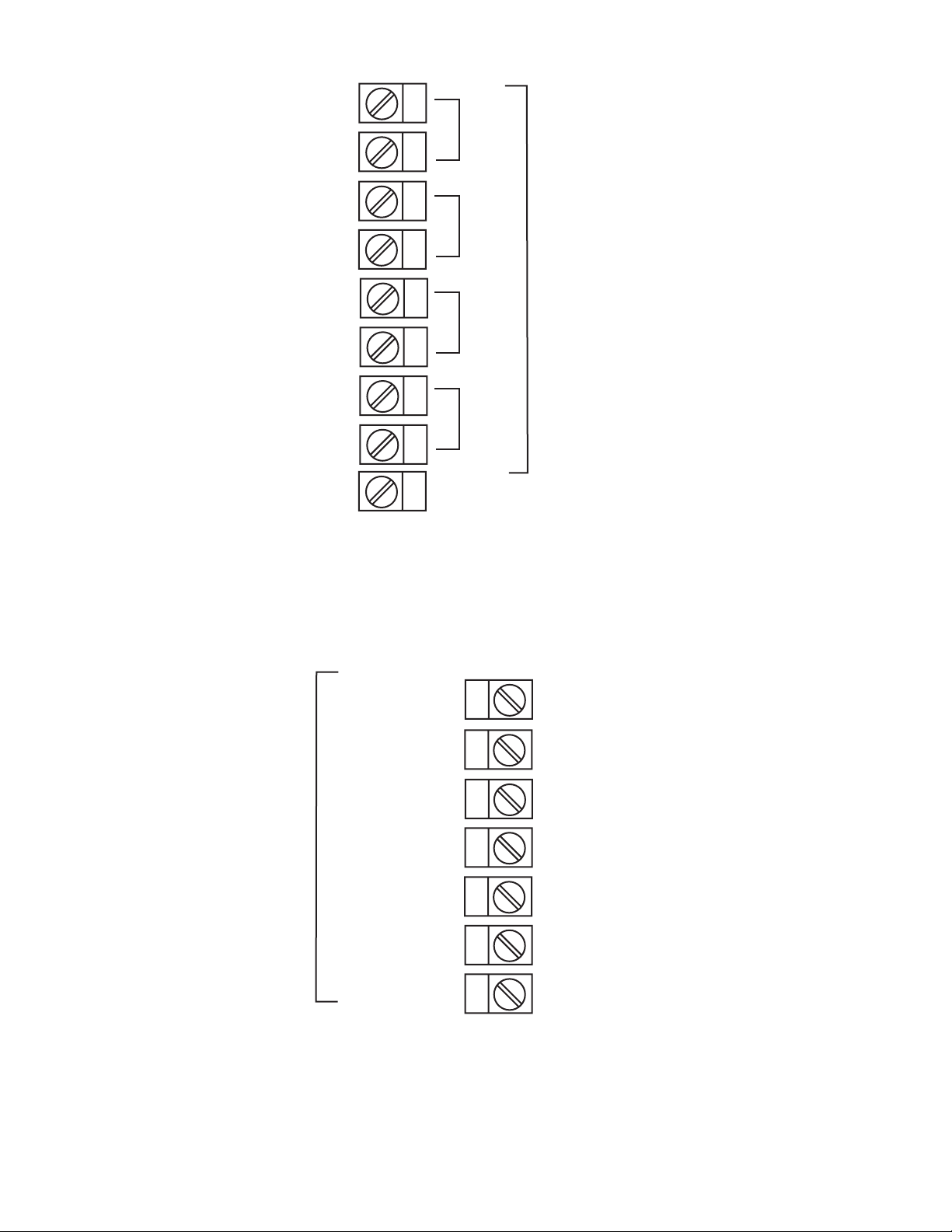
FIGURE 2-6
Rear Terminal Connections
OUTPUT 3
Relay
END OF
PROGRAM
OUTPUT
+
INPUT
Linear (mA)
-
N/O
N/C
-
+
+
RTD
Linear (V/mV)
Thermocouple
C
N/C
SSR/DC
-
9
8
7
6
5
4
3
2
1
24
N/OC
+
11
1210
23 22
13
14
15
16
17
18
19
20
21
MAINS (LINE)
SUPPLY
24V 24V
L
AC DC
N
B
RS485
A
COM
-
+
SERIAL
COMMS.
N/C
C
SSR/DC
N/O
-
+
Relay
OUTPUT 1
+
SSR/DC
N/O
MIC 1460 Manual Edition 110
C
Relay
OUTPUT 2
-
N/C
Page 17
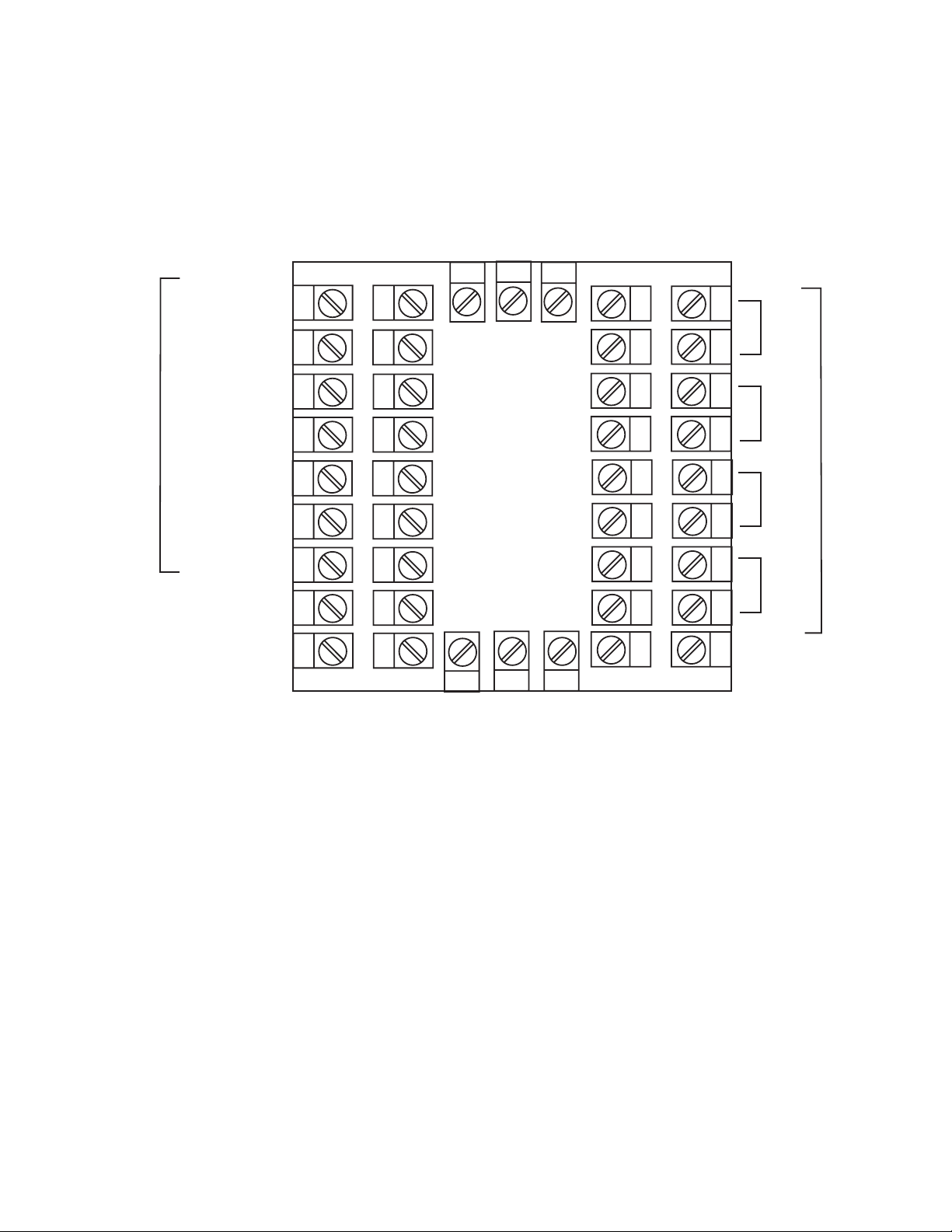
FIGURE 2-6A
RESET
RUN/HOLD
REMOTE INPUTS
X60 (FAST)
R0
R1
R2
C
33
32
31
30
29
28
27
26
25
34
#1
35
36
#2
37
38
#3
39
EVENT OUTPUTS
40
#4
41
42
MIC 1460 ManualEdition 1 11
Page 18
2.4 Input Connections
In general, all wiring connections are made to the instrument after it is installed. Avoid electrical shock. AC power wiring must not be connected to
the source distribution panel until all wiring connection procedures are
completed.
Caution: This equipment is designed for installation in an
enclosure which provide adequate protection against electric shock. Local regulations regarding electrical installation should be rigidly observed. Consideration should be
given to prevention of access to the power terminations by
unauthorized personnel. Power should be connected via a
two pole isolating switch (preferably situated near the equipment) and a 1 A fuse, as shown in Figure 2-7.
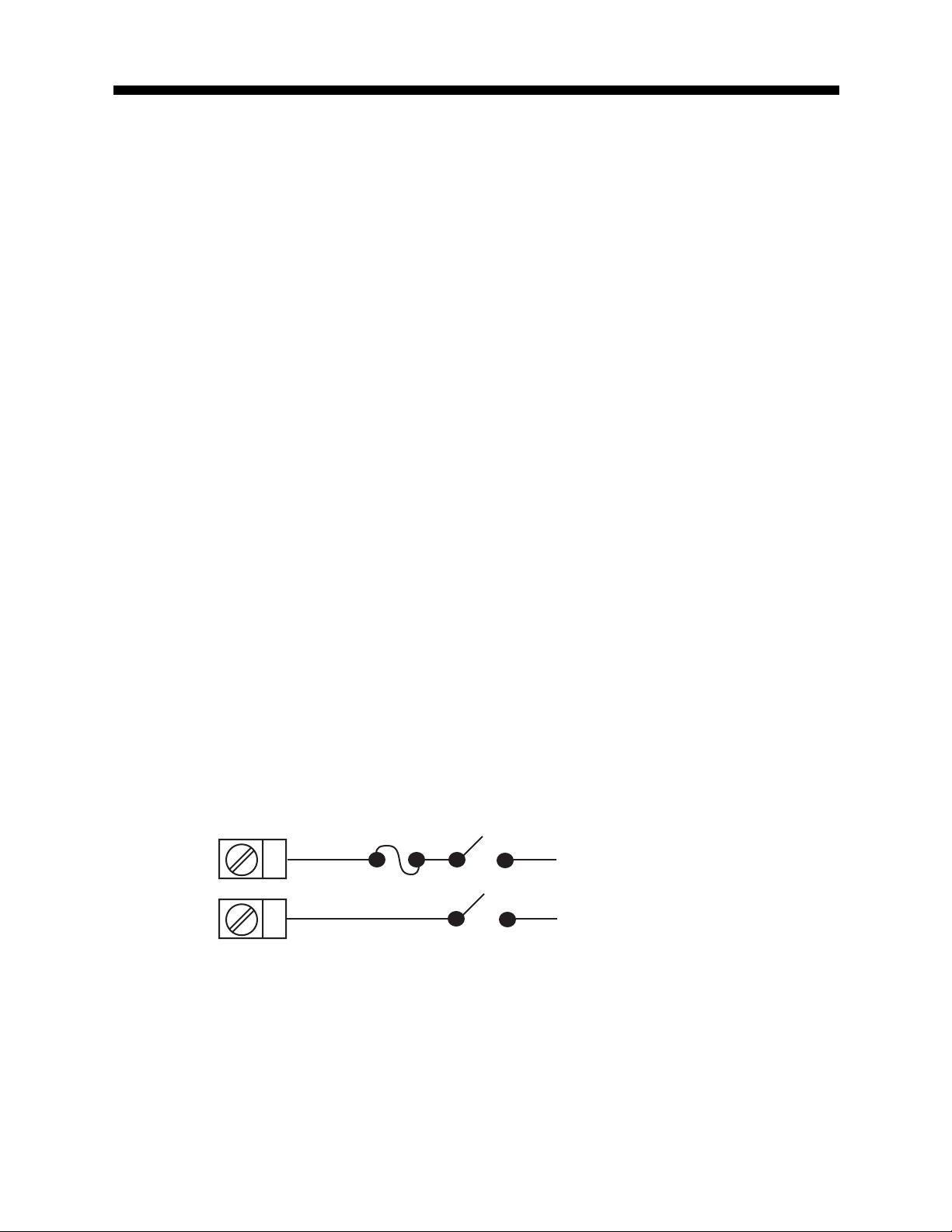
FIGURE 2-7
Main Supply
The instrument will operate on 90-264V AC 50/60 Hz mains (line) supply.
The power consumption is approximately 4 VA. If the instrument has relay
outputs in which the contacts are to carry mains (line) voltage, it is recommended that the relay contact mains (line) supply should be switched and
fused in a similar manner but should be separate from the instrument
mains (line) supply.
L
13
N
14
MIC 1460 Manual Edition 112
Line
Neutral
Page 19
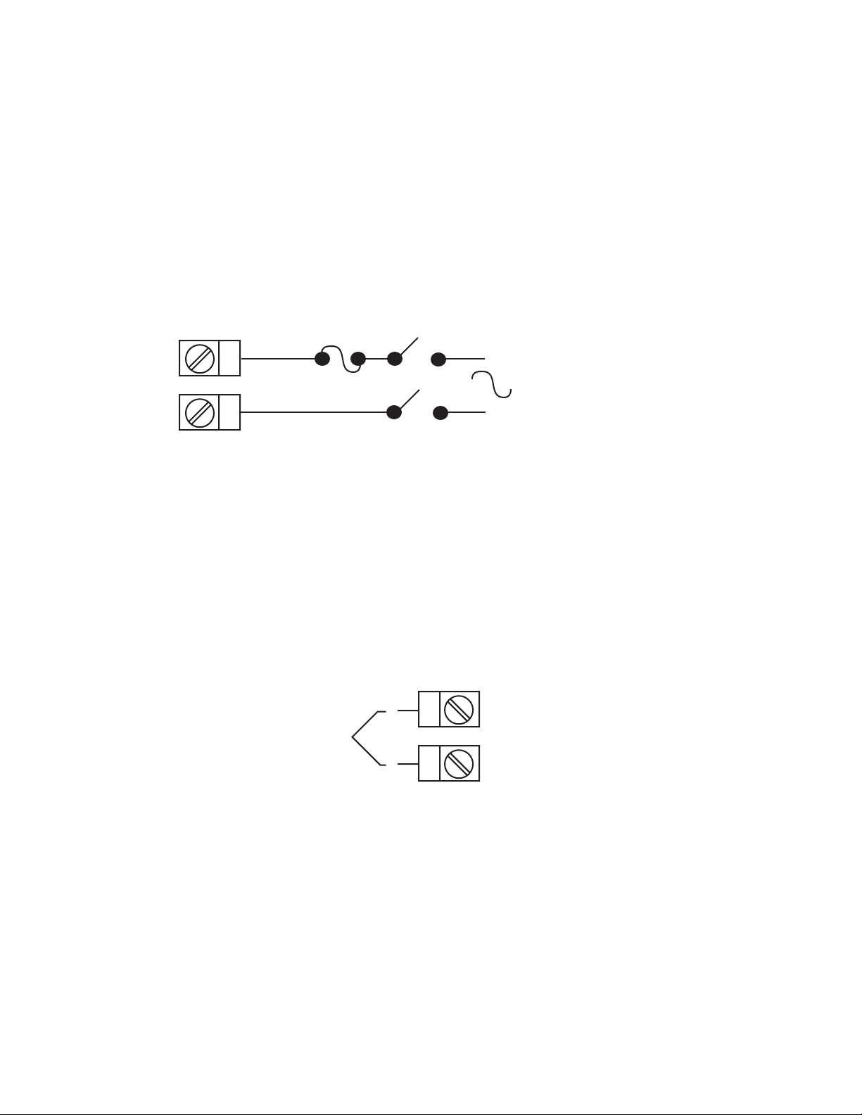
FIGURE 2-7A
24V Nominal AC/DC Supply
The supply connection for the 24V AC/DC option of the instrument are as
shown below . Power should be connected via a two pole isolating switch
and a 315 mA slow -blow (anti-surge type T) fuse. With the 24V AC/DC
supply option fitted, these terminals will accept the following supply voltage
ranges:
24V (nominal) AC 50/60Hz - 20-50V
24V (nominal) DC - 22-65V
L
13
14
N
24V AC
50/60Hz
-
24V DC
+
FIGURE 2-8
Thermocouple (T/C) Input
Make the thermocouple connections as illustrated below. Connect the
positive leg of the thermocouple to terminal 2 and the negative leg to
terminal 3.
-
+
Thermocouple
FIGURE 2-9
RTD Input
Make RTD connections as illustrated below. For a three wire RTD, connect
the resistive leg of the RTD to terminal 1 and the common legs to terminals
2 and 3. For a two wire RTD, connect one leg to terminal 2 and the other
leg to terminal 3 as shown below. A jumper wire supplied by the customer
must be installed between terminals 2 and 3. (Continued on next page)
3
2
MIC 1460 ManualEdition 1 13
Page 20

Input conditioning jumper must be positioned correctly (see Appendix B)
and Hardware Definition Code must be correct (see Appendix C).
3
2
RTD
1
FIGURE 2-10
V olt, mV Input
Make volt and millivolt connections as shown below . Terminal 2 is positive
and terminal 3 is negative. Input conditioning jumper must be positioned
correctly (see Appendix B) and Hardware Definition Code must be correct
(see Appendix C).
-
+
Linear (V/mV)
FIGURE 2-11
mADC Input
Make mADC connections as shown below. Terminal 4 is positive and terminal 1 is negative Input conditioning jumper must be positioned correctly
(see Appendix B) and Hardware Definition Code must be correct (see Appendix C).
+
3
2
1
4
3
Linear (mA)
-
MIC 1460 Manual Edition 114
2
1
Page 21
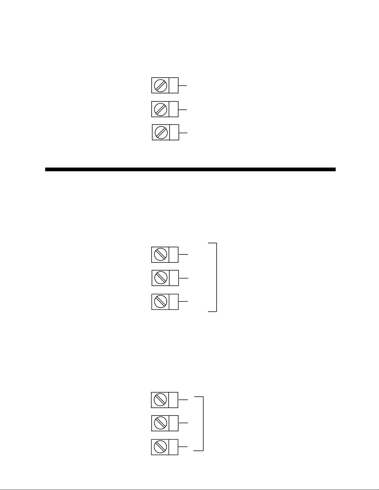
FIGURE 2-12
Remote Digital Communications - RS485
Make digital communication connections as illustrated below .
16
17
18
B
A
COM
Output Connections 2.5
FIGURE 2-13
Relay Output 1 (Control Output 1)
Connections are made to Output 1 relay as illustrated below. The contacts
are rated at 2 amp resistive, 120/240 VAC .
19
N/C
20
21
FIGURE 2-14
SSR Driver Output 1 (Control Output 1)
Connections are made to Output 1 SSR Driver as illustrated below. The
solid state relay driver is a non-isolated 0-4 VDC nominal signal. Output
impedance is 250 ohms.
19
20
21
C
Relay
N/O
-
SSR
+
MIC 1460 ManualEdition 1 15
Page 22
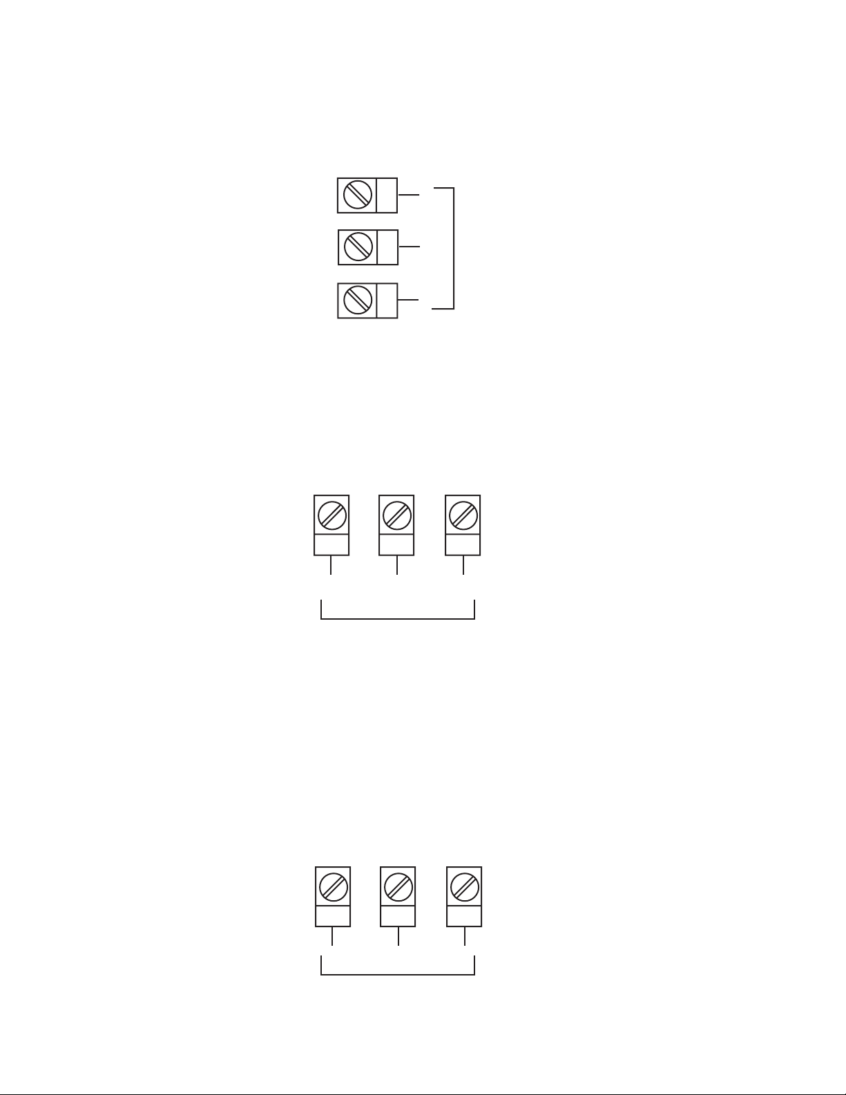
FIGURE 2-15
mADC Output 1 (Control Output 1)
Make connections for DC Output 1 as illustrated below.
19
20
21
FIGURE 2-16
Relay Output 2 (Control Output 2 OR Alarm 2)
Connections are made to Output 2 relay as illustrated below. The contacts
are rated at 2 amp resistive, 120/240 VAC.
24 23 22
-
DC
+
N/O
FIGURE 2-17
SSR Driver Output 2 (Control Output 2 OR Alarm 2)
Connections are made to Output 2 SSR Driver as illustrated below. The
solid state relay driver is a non-isolated 0-4 VDC nominal signal. Output
impedance is 250 ohms.
24 23 22
+
C
Relay
SSR
N/C
-
MIC 1460 Manual Edition 116
Page 23
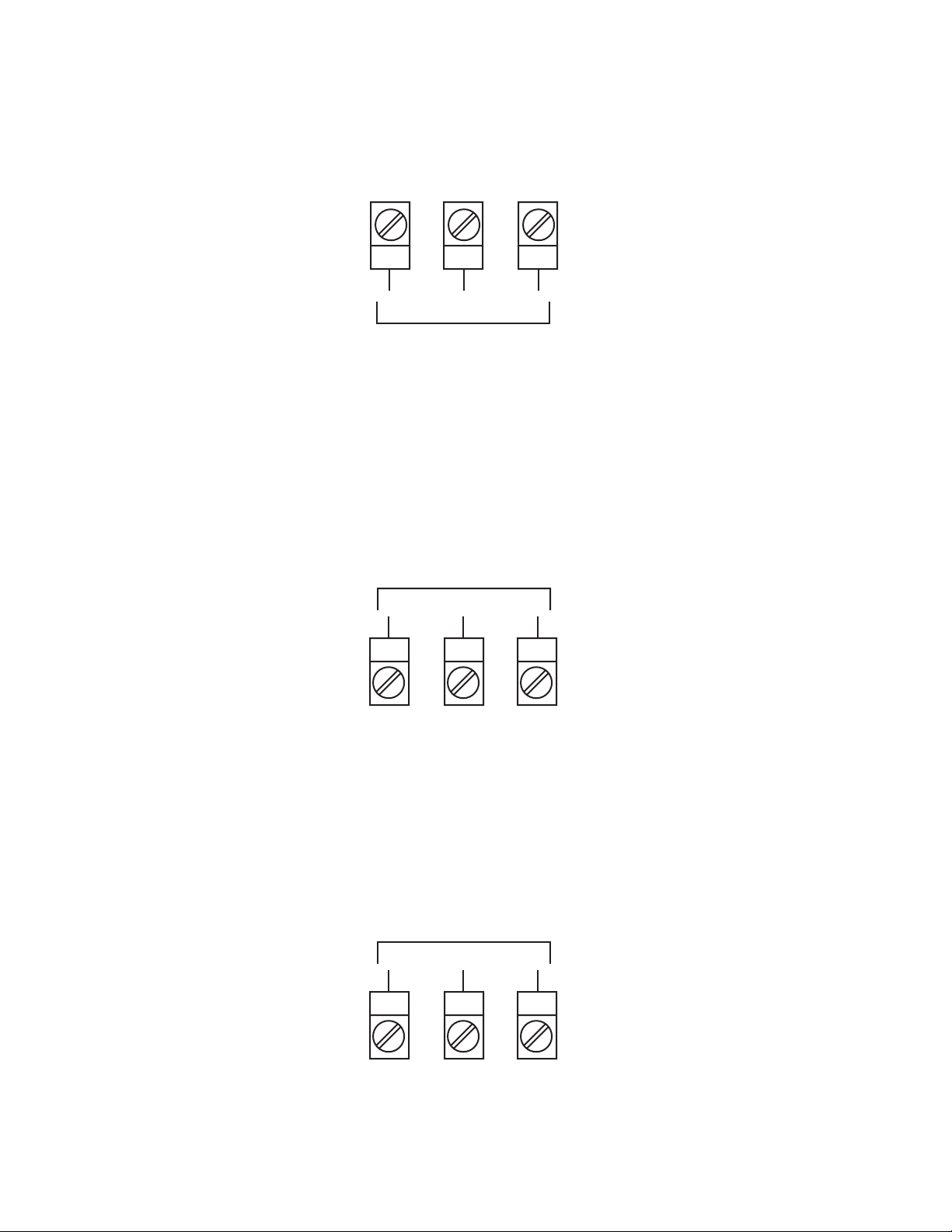
FIGURE 2-18
mADC Output 2 (Control Output 2)
Make connections for DC Output 2 as illustrated below.
24 23 22
+
DC
FIGURE 2-19
Relay Output 3 (Alarm 1)
Connections are made to Output 3 relay as illustrated below. The contacts
are rated at 2 amp resistive, 120/240 VAC.
Relay
10 11 12
FIGURE 2-20
SSR Driver Output 3 (Alarm 1)
Connections are made to Output 3 SSR Driver as illustrated below. The
solid state relay driver is a non-isolated 0-4 VDC nominal signal. Output
impedance is 250 ohms.
-
N/OCN/C
SSR
-
10 11 12
+
MIC 1460 ManualEdition 1 17
Page 24
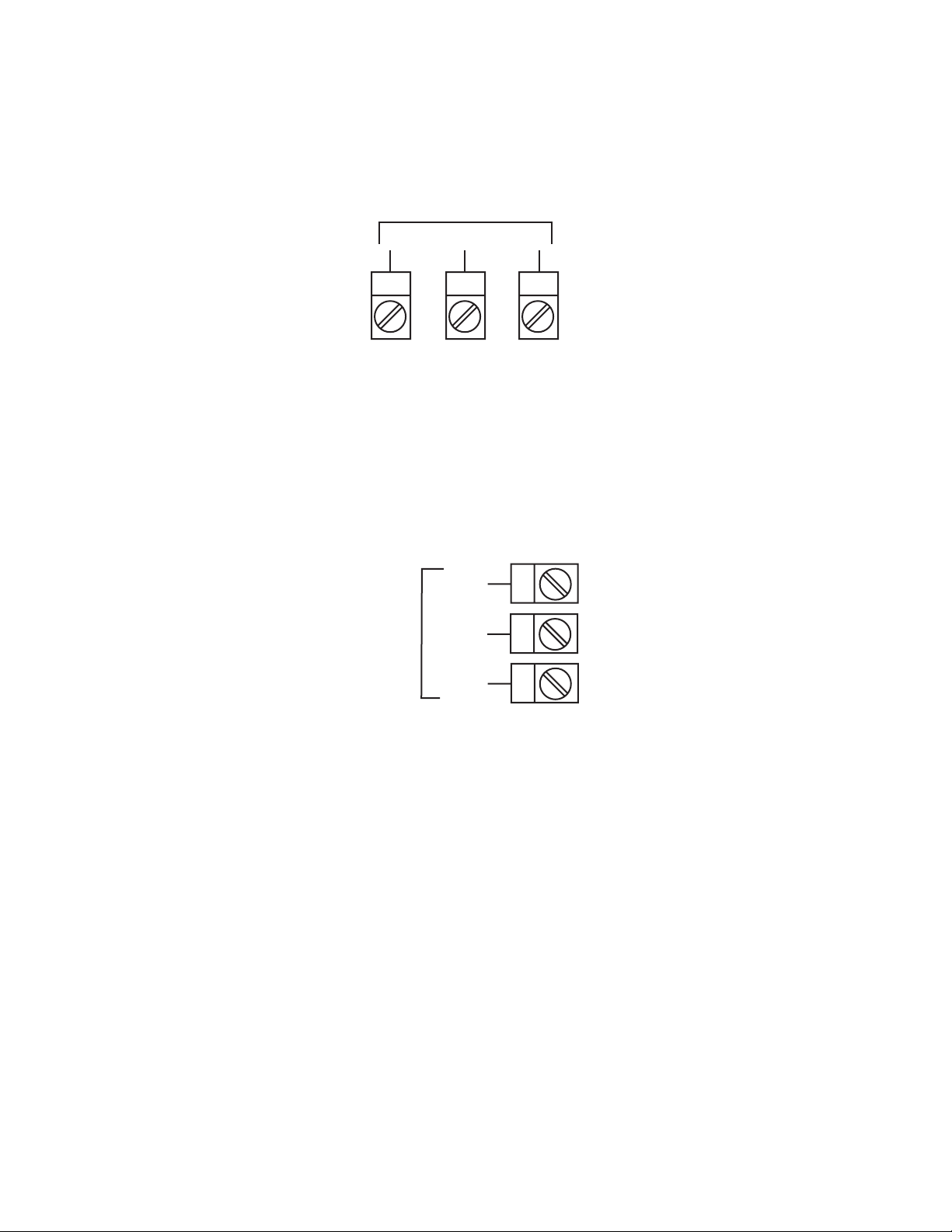
FIGURE 2-21
mADC Output 3 (Recorder Output Only)
Make connections for DC output 3 as illustrated below.
DC
-
10 11 12
FIGURE 2-22
End of Program Output
Connections are made to End of Program Output as shown below. The
contacts are rated at 5 amp resistive, 120/240 V AC.
N/O
END OF
PROGRAM
OUTPUT
C
N/C
+
9
8
7
FIGURE 2-23
Event Outputs (optional)
If the Event Outputs have been specified, make connections as shown on
top of next page. The contacts are rated at 5 amps, 120/240 VAC.
MIC 1460 Manual Edition 118
Page 25
34
35
36
37
38
39
40
41
42
#1
#2
#3
EVENT OUTPUTS
#4
FIGURE 2-24
Remote Program Inputs (optional)
If the Remote Program Control Inputs has been specified, make connections as shown.
33
R0
32
R1
31
R2
RESET
RUN/HOLD
30
29
REMOTE INPUTS
C
28
27
X60 (FAST)
Note: Only one remote connection shown for clarity.
MIC 1460 ManualEdition 1 19
Page 26

Section 3 - Operation
3.1 POWER UP PROCEDURE
Verify all electrical connections have been properly made before applying
power to the instrument.
If the instrument is being powered for the first time, it may be desirable to
disconnect the controller output connections. The instrument will be into
control following the power up sequence and the output(s) may turn ON .
During Power up, a self-test procedure is initiated during which all LED
segments in the two front panel displays appear and all LED indicators are
ON . When the self-test procedure is complete, the instrument reverts to
normal operation.
Note: When power is first applied, a delay of approx. 3 seconds will be
seen before the displays light up.
3.2 KEYPAD OPERATION
Mode Key
MODE
Changes mode of instrument.
Scroll Key
Displays the next parameter in sequence (indicated by Message display).
Up Key
Increments displayed parameter value/cycles through options.
Down Key
Decrements displayed parameter value/cycles through options.
MIC 1460 Manual Edition 120
Page 27
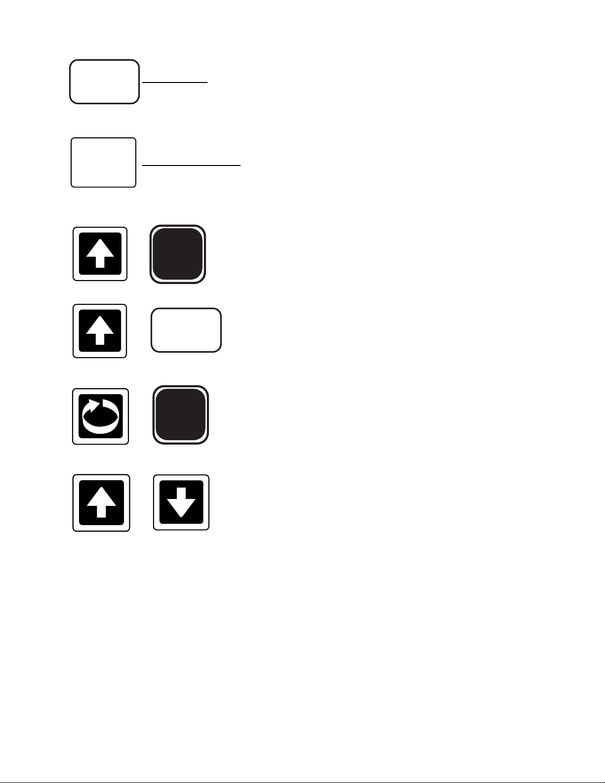
PROF
PROF Key
Cycles through Program (profile) numbers.
RUN/HOLD
RUN/HOLD Key
Runs, holds or aborts current program (profile).
Selects/de-selects Self-T une and Pre-Tune (when
MODE
+
+
+
PROF
MODE
message display shows appropriate message).
Jumps to next segment, when program is
running.
Selects/de-selects Manual Control
+
Sets a segment to Dwell when defining a
program.
MIC 1460 ManualEdition 1 21
Page 28
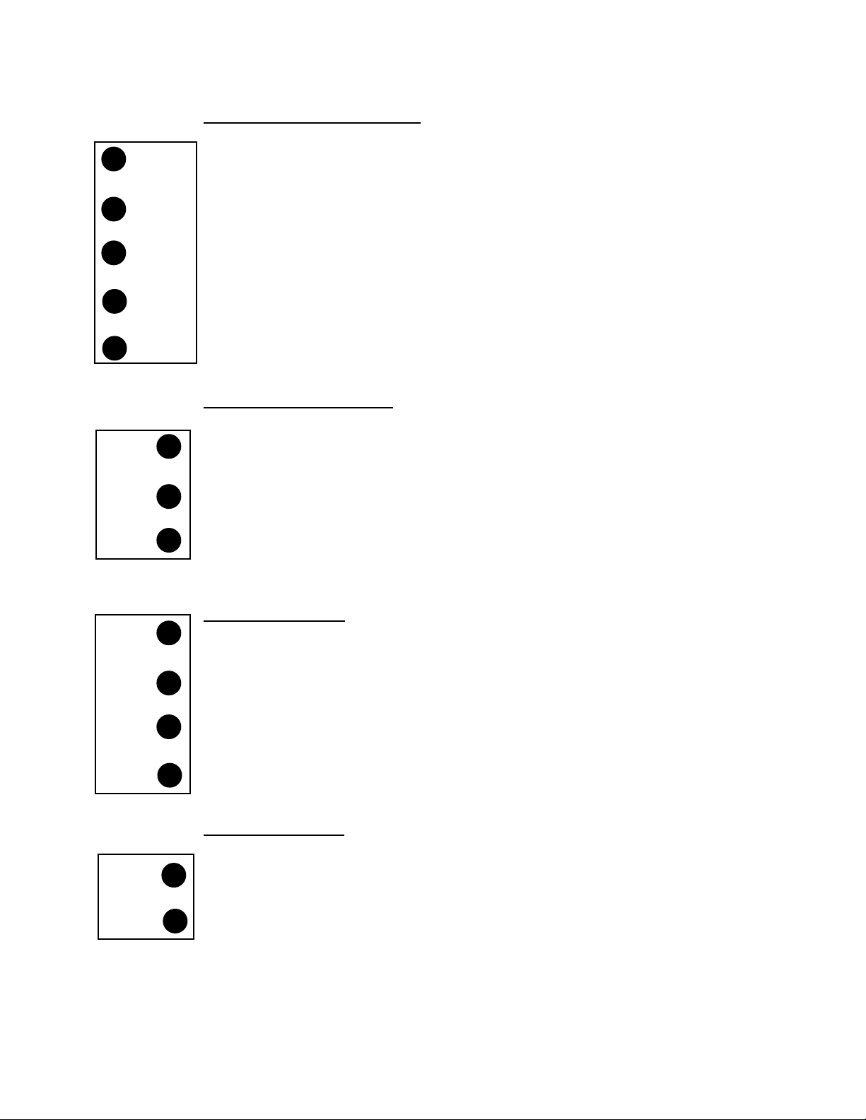
3.3 INDICATORS
Control Status Indicators
AT
ALM
OP1
OP2
MAN
RUN
HLD
x60
A T - ON when Self-Tune is active; flashes when Pre-
Tune is active.
ALM - Flashes when any alarm is active.
OP1 - ON when primary control output is active.
OP2 - ON when secondary control output (if fitted) is
active.
MAN - ON when Manual Control is selected.
Run Status Indicators
RUN - ON - Program running or (if HLD ON also) held
Flashing - Program in Delayed state
HLD - ON - Program held
Flashing - Program in Auto-Hold
x60 - OFF - timebase = hours/minutes
ON - timebase = minutes/seconds
EV1
EV2
EV3
EV4
SET
PRG
Event Indicators
Each indicates the status (active or inactive) of a user-defined
event (OFF = inactive, ON = active)
Mode Indicators
SET - ON when Controller Define Mode or Program
Define Mode is entered; flashes when viewing
parameters in Controller Define Mode or Program
Define Mode after entry from Base Mode.
PRG - ON when Program Define Mode is entered.
MIC 1460 Manual Edition 122
Page 29
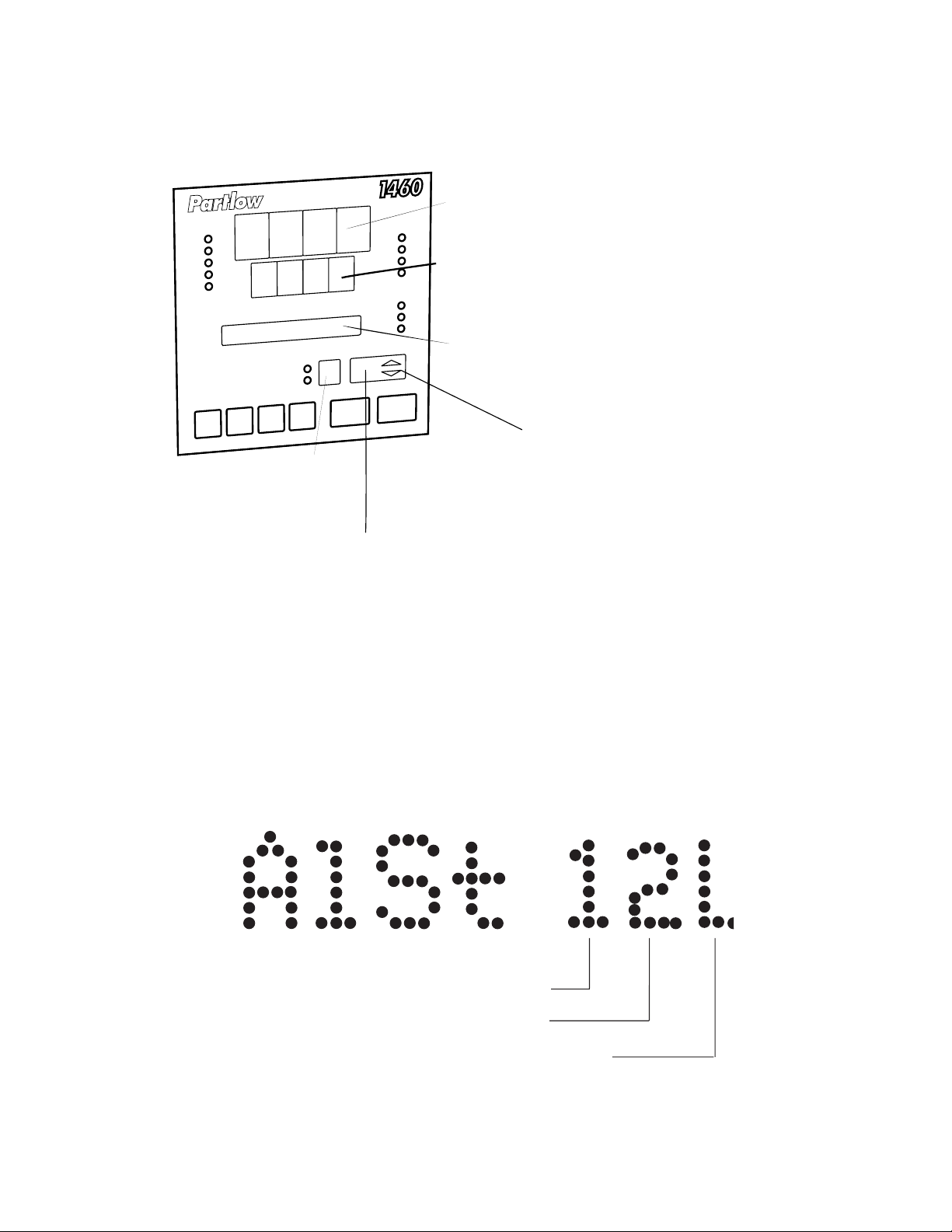
3.4 DISPLAYS
PROGRAM NUMBER
Number of currentlyselected program
UPPER DISPLAY
Process Variable value
LOWER DISPLAY
Setpoint value or value/setting
of parameter being viewed/edited.
MESSAGE DISPLAY
CURRENT RAMP STATE
= UP Ramp
= DOWN Ramp
BOTH ON = Dwell
Both flashing = In Manual Control while
program is running
SEGMENT NUMBER
Number of current segment
3.5 ALARM STATUS INDICATION
When any alarm is active, the ALM indicator will flash. To view the main
status in the Message Display, press the SCROLL key until a display appears in the form:
Appears only if Alarm 1 is active
Appears only if Alarm 2 is active
Appears only if the Loop Alarm is active
MIC 1460 ManualEdition 1 23
Page 30
3.6 VIEWING PROGRAM AND CONTROLLER PARAMETERS
In Base Mode (i.e. with no program currently running or held), the MODE
key gives "view only" access to Program Define Mode and Controller Define Mode.
VIEW ONLY
CONTROLLER
DEFINE
MODE
BASE
MODE
MODE
VIEW ONLY
PROGRAM
DEFINE
MODE
MODE
MODE
3.7 ADJUSTING THE CONTROLLER SETPOINT
With the Setpoint Programmer in Base Mode (i.e. with the RUN, HLD, SET,
and PRG indicators OFF), the two main displays will show the process
variable value (upper display) and the setpoint value (lower display - Read
Only). To change the setpoint value:
1. Press the SCROLL key, the Message Area will display:
2. Use the UP and DOWN keys to change the setpoint value (in the
lower display) as required.
3. When the setpoint value is set as desired, press the SCROLL key
again to return to the initial display.
MIC 1460 Manual Edition 124
Page 31

3.8 MANUAL CONTROL
In any mode except Configuration Mode, the operator may select manual
control of the process by simultaneously pressing the SCROLL and MODE
keys, provided Manual Mode is enabled in Controller Define Mode. The
instrument will then enter Base Mode or (if a program is currently running)
Program Run Mode with the program held. The Message Display will
show:
and the lower Main Display will show the power output value, which may
then be adjusted using the UP and DOWN keys. While manual control is
being used, the power output display is included in the displays available in
Base Mode and Program Run Mode.
To cancel manual control, press the SCROLL and MODE keys simultaneously, wereupon the power out value display and the Power message
display will disappear and the Setpoint Controller will remain in whatever
mode prevailed when manual control was cancelled (if this is Program Run
Mode, the currently-running program will be resumed from the point at
which it was held).
3.9 USING THE PRE-TUNE FACILITY
The Pre-Tune facility is used to set the instrument's PID control parameters
to values which are approximately correct in order to provide a base from
which the Self-Tune facility may subsequently optimize tuning. Pre-T une
may be activated as follows:
1. With the instrument in Base mode (with the RUN and HLD indicators
OFF), press the SCROLL key until the Message Display shows:
MIC 1460 ManualEdition 1 25
Page 32

and the lower Main Display shows:
2. Press the MODE and UP keys to change the lower Main Display to:
indicating that the Pre-Tune facility is now activated. The AT indicator
will flash.
NOTES:
1. If the process variable is within 5% of the input span from the
setpoint, the Pre-Tune facility cannot be activated and any attempt
to do so will have no effect.
2. Since the Pre-Tune facility is a single-shot operation, it will automatically de-activate itself once the operation is complete.
To de-activate the Pre-Tune facility manually (with the instrument in Base
Mode), press the SCROLL key to obtain the same Message Displays
above; then press the MODE and UP keys simultaneously to change the
lower Main display from ON to OFF.
3.10 USING THE SELF-TUNE FACILITY
The Self-T une facility is used to optimize tuning while the Controller part of
the instrument is operating. Self Tune may be activated as follows:
1. With the instrument in Base Mode (with RUN and HLD indicators
OFF), press the SCROLL key until the Message Display shows:
MIC 1460 Manual Edition 126
Page 33

and the lower Main Display shows:
2. Press the MODE and UP keys to change the lower Main Display to:
indicating that the Self-T une facility is now activated. The AT indicator is
on continuously.
To de-activate the Self-Tune facility, press the SCROLL key to obtain the
same Message Display as above; then press the MODE and UP keys simultaneously to change the lower Main Display from ON to OFF.
MIC 1460 ManualEdition 1 27
Page 34

Section 4 - Configuration
4.1 ENTRY INTO CONFIGURATION MODE
To enter Configuration Mode:
1. Ensure that the instrument is powered down.
2. Power-up the instrument and within 30 seconds of power-up, hold
down the UP and SCROLL keys simultaneously for approximately five
seconds.
NOTE: This must be the first key action after power-up.
The instrument will then enter Configuration Mode, whereupon the upper
and lower main displays will initially be of the form:
showing the current input code selected, and the Message Display will
show:
The user may then step through the Configuration Mode parameters using
the SCROLL key. For each parameter, the Message Display will show a
legend identifying that parameter and the lower main display will show the
current setting of that parameter. The setting may be adjusted using the
UP/DOWN keys. As soon as the setting is changed, the lower main display
will flash, indicating that the new setting has yet to be confirmed. When the
setting is as required, it may be confirmed by pressing the MODE key,
whereupon the upper display will stop flashing.
MIC 1460 Manual Edition 128
Page 35

NOTE: Changes to the setting of certain Configuration Mode parameters (i.e. input range, output use and type) will cause the Program Define Mode and Controller Define Mode parameters to be
automatically set to their default values.
4.2 HARDWARE DEFINITION CODE
This parameter is a special facility in Configuration Mode, which is used to
specify the hardware fitted (input type, output types, etc); this must be compatible with the hardware actually fitted. It can be accessed, with the instrument in Configuration Mode, by simultaneously pressing the DOWN
and SCROLL keys. The Message Display will then show:
and lower main display will be of the form:
Input Type
1 RTD/Linear (mV)
2 Thermocouple
3 Linear DC (mA)
4 Linear DC (V)
Output 1 Type
1 Relay Output
2 SSR Output
3 DC Output (0-10V)
4 DC Output (0-20mA)
5 DC Output (0-5V)
7 DC Output (4-20mA)
Output 3 Type
0 None
1 Relay Output (Alarm Output Only)
2 SSR Output (Alarm Output Only)
3 DC Output 0-10V (Recorder Output Only)
4 DC Output 0-20mA (Recorder Output Only)
5 DC Output 0-5V (Recorder Output Only)
7 DC Output 4-20mA (Recorder Output Only)
Output 2 Type
0 None
1 Relay Output (Control or Alarm Output)
2 SSR Output (Control or Alarm Output)
3 DC Output 0-10V (Control Output Only)
4 DC Output 0-20mA (Control Output Only)
5 DC Output 0-5V (Control Output Only)
7 DC Output 4-20mA (Control Output Only)
MIC 1460 ManualEdition 1 29
Page 36

The displayed code may be incremented/decremented using the UP/
Event Output
Option PCB
fitted
DOWN keys as required. The maximum setting available for this code is
4777. For example, the code for a thermocouple input, 4-20mA DC primary
output (Output 1) and relay Output 3 would be 2701. When the code is first
altered, the code display will flash, until the desired value is displayed and
confirmed by pressing the MODE key.
NOTE: It is essential that this code is changed promptly whenever
there is a change to the instrument's hardware configuration
(change of input/output type, alarm/recorder output added/removed
etc.). The instrument software depends upon this code to operate
correctly.
Hardware Definitions may be viewed as Read Only displays in Base Mode
by pressing the SCROLL and DOWN keys simultaneously.
While the Hardware Definition Code is displayed, pressing the SCROLL key
will cause the Message Display to change to:
and the lower main display to change to one of:
No option PCB
fitted
Both Option
PCBs fitted
Digital Input
Option PCB
fitted
The desired setting can be achieved using the UP/DOWN keys.
MIC 1460 Manual Edition 130
Page 37

Press the SCROLL key to change the Message Display to:
and the lower main display to one of:
RS485
Communications
Option PCB not
fitted
RS485
Communications
Option PCB fitted -
Programmer acting as
slave device
Option PCB fitted -
Programmer acting as
RS485
Communications
master device
The desired setting can be achieved using the UP/DOWN keys.
To exit from the Hardware Definition Code facility, press the DOWN and
SCROLL keys simultaneously (which will cause a return to the normal Configuration Mode). Alternatively, either of the methods of exit from Configuration Mode may be used here.
4.3 CONFIGURATION MODE PARAMETERS
The Configuration Mode parameters are presented for view/edit in the following sequence:
MESSAGE AVAILABLE
STEP DESCRIPTION DISPLAY FUNCTION SETTING
1 Primary Input Input Code display- See App. A
Range
5
ed defines
input type/
range (see
App. A)
2 Control Action Control Specifies dir - Direct
control Acting
action of rEu- Reverse
Output 1
1
Acting
MIC 1460 ManualEdition 1 31
Page 38

MESSAGE AVAILABLE
STEP DESCRIPTION DISPLAY FUNCTION SETTINGS
3 Alarm 1 T ype Alarm 1 Specifies P_hi- Process
Alarm 1 High
Operation P_Lo-Process
Low
dE-Deviation
bAnd-Band
nonE-None
4 Alarm 2 T ype Alarm 2 Specifies P_hi-Process
Alarm 2 High
Operation P_Lo-Process
Low
dE-Deviation
bAnd-Band
nonE-None
5 Alarm Inhibit Inhibit Specifies nonE-No
which alarms inhibit
are inhibited ALA1-Alarm1
ALA2-Alarm 2
both-Both
Alarms
6 Output 2 Usage Out2 Use Specifies out2-Control
use of Output
Output 2
2
A2_d-Alarm 1
(direct)
A2_r-Alarm 2
(reverse)
Or_d-Alarm 1
OR 2
(direct)
(Continued on next page)
MIC 1460 Manual Edition 132
Page 39

MESSAGE AVAILABLE
STEP DESCRIPTION DISPLAY FUNCTION SETTINGS
Or_r-Alarm 1
OR 2
(reverse)
Ad_d-Alarm 1
AND 2
(direct)
Ad_r-Alarm 1
AND 2
(reverse)
LP_d-Loop
Alarm
(direct)
LP_r-Loop
Alarm
(reverse)
7 Output 3 Useage Out3 Use Specifies Al_d-Alarm 1
use of (direct)
Output 3
3
Al_r-Alarm 1
(reverse)
Or_d-Alarm 1
OR 2
(direct)
Or_r-Alarm 1
OR 2
(reverse)
Ad_d-Alarm 1
AND 2
(direct)
Ad_r-Alarm 1
AND 2
(reverse)
LP_d-Loop
Alarm
(direct)
(Continued on the next page)
MIC 1460 ManualEdition 1 33
Page 40

MESSAGE AVAILABLE
STEP DESCRIPTION DISPLAY FUNCTION SETTINGS
LP_r-Loop
Alarm
(reverse)
rEcS-Rcdr
Output
(SP)
rEcP-Rcdr
Output
(PV)
8 Segment Mode Seg Mode Defines para- ti- Time
meter used to rA-Ramp Rate
specify duration
of each segment
(along with final
SP value)
9 Baud Rate
6
Baud Rate Selects Baud Numeric
Rate for RS485 value: 1200,
Comms. 2400, 4800 or
9600
10 Address
6,7
Address Selects RS485 Numeric
comm. address value in range
1-32
11 CJC
4
Enable/ CJC Enables/ EnAb-enabled
Disabled disables cold diSA-disabled
junction comp.
12 Lock Code Lock Displays Read Only-
Code current lock no adjustment
code value in Conf. Mode
For Notes on Configuration Mode Parameters, see next page.
MIC 1460 Manual Edition 134
Page 41

Notes on Configuration Mode Parameters
1. If the secondary output is chosen as Output 2 (COOL) control output, its
action is always the compliment of the action of Output 1.
2. The default setting for Output 2 Usage is Alarm 2 hardware output,
direct-acting (if relay/SSR output) or Output 2 - COOL (if DC output).
3. The default setting for Output 3 Usage is Alarm 1 hardware output,
direct-acting (if relay/SSR output) or Process Variable Recorder Output
(if DC output)
4. This parameter does not appear in the sequence if the input type
selected is not thermocouple. If the CJC is disabled, the initial display in
Operator Mode will show horizontal bars flashing in the lower display.
5. The primary input default setting is dependent upon the hardware fitted,
as indicated in the Hardware Definition Code.
6. These parameters do not appear if the Hardware Definition Comms
parameters is set to nonE.
7. This parameter does not appear if the Programmer communications
option is set to operate in Master mode.
4.4 ALARM INHIBIT FACILITY
On power-up, an "alarm" condition may occur, based on the alarm value,
the process value and, if appropriate to the alarm type, the setpoint value.
This would normally activate an alarm; however, if the pertinent alarm is
inhibited, the alarm indication is suppressed and the alarm will remain inactive. This will prevail until the "alarm" condition returns to the "inactive"
state, whereafter the alarm will operate normally.
4.5 EXIT FROM CONFIGURATION MODE
To leave Configuration Mode, depress the UP and SCROLL keys simultaneously.
Note: An automatic exit to Base Mode will be made if, in Configuration Mode, there is no front panel key activity for five minutes.
The exit is made via the power-up self-test routines which includes a lamp
test.
MIC 1460 ManualEdition 1 35
Page 42

Section 5 - Defining The Controller Parameters
(Controller Define Mode)
Entry can be made into this mode from Program Define Mode, Program
Run Mode or Base Mode.
To enter from Base Mode or Program Run Mode:
1. Press the SCROLL and UP keys simultaneously. The lower display
will show 0 and the Message Display will show:
2. Use the UP and DOWN keys to set the value in the lower Main Display to the correct Lock Value (defined by the user in Controller Define
Mode) and press the SCROLL key. The Setpoint Programmer is now in
Program Define Mode.
Note: If an incorrect Lock Code value is entered, the instrument will
return to the original mode (i.e. Base Mode or Program Run Mode)
3. Press the MODE key.
The instrument is now in the Controller Define Mode.
Upon entry into the Controller Define Mode, the SET indicator will then
come ON and the first of the Controller parameters (Input Filter Time Constant) will be presented for editing/viewing. Using the SCROLL key, step
through the sequence of Controller parameters, editing as required (using
the UP/DOWN keys).
MIC 1460 Manual Edition 136
Page 43

5.1 CONTROLLER PARAMETERS
The Controller parameters appear in the following sequence:
MESSAGE AVAILABLE
STEP DESCRIPTION DISPLAY FUNCTION SETTING
1 Input Filter Time Filter Defines time 0.0 seconds
Constant constant for (filter OFF) to
input filter 100.0 sec(removes onds in 0.5
extraneous increments.
impulse from Default =
the process 2.0 seconds.
variable input.
2 Process V ariable Offset Modifies actual For linear
Offset
1
PV value: input, limited
Offset PV + by Scale
Actual PV = Range Max.
PV value used and Scale
Range Min.
Default=0.
3 Output 1 Power Out1 Indicates Not adjustable
current Output1 "Read Only"
power level
4 Output 2 Power
2
Out2 Indicates No adjustable
current Output2 "Read Only"
power level
5 Proportional P.Band 1 Defines portion 0.0% (ON/
Band 1 (PB1) of input span OFF control)
in which the to 999.9%
Output 1 power of input span.
level is propor- Default =
tional to the 10.0%
(offset) process
variable value
MIC 1460 ManualEdition 1 37
Page 44

MESSAGE AVAILABLE
STEP DESCRIPTION DISPLAY FUNCTION SETTING
6 Proportional P.Band 2 Defines portion 0.0% (ON/
Band 2
2
(PB2) of input span OFF control)
in which the to 999.9%
Output 2 power of input span.
level is propor- Default =
tional to the 10.0%
(offset) process
variable value
7 Reset
3
Reset Integral Time 1 second to
Constant 99 minutes
59 seconds
per repeat
8 Rate
3
Rate Derivative 00 seconds to
Time Constant 99 minutes
59 seconds
9 Overlap or Overlap Defines the -20% to +20%
Deadband
4
portion of the (negative
proportional band value =
(PB1 + PB2) deadband,
over which both positive
outputs are value =
active (overlap) overlap)
or neither output Default = 0%
is active
(deadband)
10 Bias Bias Bias applied to 0% to 100%
(Manual Reset)
3
output power, (Output1 only)
expressed as -100% to
a percentage +100%
of output power (Output 1 &
Output 2)
Default=25%
MIC 1460 Manual Edition 138
Page 45

MESSAGE AVAILABLE
STEP DESCRIPTION DISPLAY FUNCTION SETTING
11 ON/OFF Diff 1 Switching 0.1% to 10%
Differential
5
Diff 2 differential for of input span
Diff 1 output (Diff 1 Default=0.5%
or Diff 2) or both
outputs (Diff) set
to ON/OFF
control
(PB1, PB2 or
both = 0%)
12 Setpoint SP High The maximum Current
High Limit
6
limit for setpoint setpoint value
adjustment. to input
Should be set Range Max.
to a value which Default =
prevents Input Range
setpoint values Max.
causing damage
to the process.
13 Setpoint SP Low The minimum Input Range
Low Limit
6
limit for setpoint Min. to current
adjustment. setpoint
Should be set value.
to a value which Default =
prevents Input Range
setpoint values Minimum.
causing damage
to the process.
MIC 1460 ManualEdition 1 39
Page 46

MESSAGE AVAILABLE
STEP DESCRIPTION DISPLAY FUNCTION SETTING
14 Recorder Output Rec High The value of -1999 to 9999
Scale Maximum
7
the process (decimal point
variable or as for the
setpoint (as process
applicable) variable
for which the input range).
recorder output Default =
is a minimum. Input Range
Max.
15 Recorder Output Rec Low The value of -1999 to 9999
Scale Minimum
7
the process (decimal point
variable or as for the
setpoint (as process
applicable) variable
for which the input range).
recorder output Default =
is a minimum. Input Range
Min.
16 Output Power Out High Limits the 0% to 100%
Limit
3
power level of
Output 1 (used
to protect the
process).
17 Output 1 CycTime1 Limits 0.5, 1, 2, 4,
Cycle Time
8
frequency of 8, 16, 32, 64,
operation of 128, 256 or
output relay 512 seconds.
to maximize Default =
relay life. 32 seconds.
MIC 1460 Manual Edition 140
Page 47

MESSAGE AVAILABLE
STEP DESCRIPTION DISPLAY FUNCTION SETTING
18 Output 2 CycTime2 Limits 0.5, 1, 2, 4,
Cycle Time
8
frequency of 8, 16, 32, 64,
operation of 128, 256 or
output relay 512 seconds.
to maximize Default =
relay life. 32 seconds.
19 Process High HiAlarm1 If Alarm 1 is Input Range
Alarm 1 value a Process High Max. to Input
Alarm, the Range Min.
value of Default =
process Input Range
variable at or Max.
above which
Alarm 1 will
be active.
20 Process Low LoAlarm1 If Alarm 1 is Input Range
Alarm 1 value a Process Low Max. to Input
Alarm, the Range Min.
value of Default =
process Input Range
variable at or Min.
below which
Alarm 1 will
be active.
21 Band Alarm 1 BaAlarm1 If Alarm 1 is ± (input span)
value a Band Alarm, from setpoint.
the band of Default = five
process input units.
variable values
(centered on
the setpoint)
outside which
the process
variable will
cause this alarm
to be active.
MIC 1460 ManualEdition 1 41
Page 48

MESSAGE AVAILABLE
STEP DESCRIPTION DISPLAY FUNCTION SETTING
22 Deviation DeAlarm1 If Alarm 1 is ± (input
(High/Low) a Deviation range)
Alarm 1 High/Low from setpoint
value Alarm, gives Default =
a value above five input
(positive value) range units.
or below
(negative value)
the setpoint.
If the process
variable deviates
from the setpoint
by a margin
greater than this
value, the alarm
becomes active
23 Alarm 1 Al1 Hyst Value defines 1 LSD to 10%
Hysteresis a hysteresis of input span
value band on the (0 is an
"safe" side invalid value)
of the Alarm 1
value
24 Process High HiAlarm2 If Alarm 2 is Input Range
Alarm 2 value a Process High Max. to Input
Alarm, the Range Min.
value of Default =
process Input Range
variable at or Max.
above which
Alarm 2 will
be active
MIC 1460 Manual Edition 142
Page 49

MESSAGE AVAILABLE
STEP DESCRIPTION DISPLAY FUNCTION SETTING
25 Process Low LoAlarm2 If Alarm 2 is Input Range
Alarm 2 value Process Low Max. to Input
Alarm, the Range Min.
value of Default =
process Input Range
variable at or Min.
below which
Alarm 2 will
be active
26 Band Alarm 2 BaAlarm2 If Alarm 2 is ± (input span)
value a Band Alarm, from setpoint.
the band of Default =
process five input
variable units.
values
(centered on
the setpoint)
outside which
the process
variable will
cause this
alarm to be
active.
MIC 1460 ManualEdition 1 43
Page 50

MESSAGE AVAILABLE
STEP DESCRIPTION DISPLAY FUNCTION SETTING
27 Deviation DeAlarm2 If Alarm 2 is a ± (input
(High/Low) Deviation range)
Alarm 2 value High/Low from setpoint.
Alarm, gives Default =
a value above five input
(positive value) range units
or below
(negative value)
the setpoint.
If the process
variable deviates
from the setpoint
by a margin
greater than this
value, the alarm
becomes active.
28 Alarm 2 Al2 Hyst A non-zero 1 LSD to 10%
Hysteresis value value defines of input span
a hysteresis
band on the
"safe" side of
the Alarm 2
value
29 Loop Alarm Loop Alm Enables/ 0 (disabled)/
Enable disables Loop 1 (enabled)
Alarm Default =
0 (disabled)
MIC 1460 Manual Edition 144
Page 51

MESSAGE AVAILABLE
STEP DESCRIPTION DISPLAY FUNCTION SETTING
30 Loop AlarmTime LpAtime If ON/OFF 1 second to
control is 99 minutes
selected 59 seconds.
(i.e. PB1=0) Default =
and Loop 99 minutes
Alarm is 59 seconds
enabled, this
defines the
duration of the
saturation
condition
after which the
Loop Alarm
is activated
31 Scale Range Range Pt For linear 0 XXXX
Decimal Point
9
inputs, defines 1 XXX.X
the decimal (default)
point position 2 XX.XX
3 X.XXX
32 Scale Range Range Hi For linear -1999 to 9999
Maximum
9
inputs, defines (decimal point
the scaled as defined
input value by Scale
when the Range
process Decimal
variable input Point
is at its parameter).
maximum Default =
value. 100.0
MIC 1460 ManualEdition 1 45
Page 52

MESSAGE AVAILABLE
STEP DESCRIPTION DISPLAY FUNCTION SETTING
33 Scale Range Range Lo For linear -1999 to 9999
Minimum
9
inputs, defines (decimal point
the scaled as defined
input value by Scale
when the Range
process Decimal
variable input Point
is at its parameter).
minimum Default = 0.0
value.
34 Auto Pre-Tune Auto PT Determines OFF =
Enable/Disable whether the Disabled
Pre-Tune ON = Enabled
facility is Default = OFF
automatically
activated on
power-up
35 Manual Control A/M Enab Enables/ OFF =
Enable/Disable disables Disabled
operator ON = Enabled
selection of Default = Off
manual control
36 Communications ComWrite Enables/ OFF =
Write Enable/ disables Disabled
Disable
10
changing of ON = Enabled
parameter Default = Off
values or
settings via the
RSs485
communications
link.
MIC 1460 Manual Edition 146
Page 53

MESSAGE AVAILABLE
STEP DESCRIPTION DISPLAY FUNCTION SETTING
37 Lock value Lock Defines the 0 to 9999
four-digit code Default = 10
required to
enter Program
define Mode or
Controller
Define Mode
Notes on Configuration Define Mode Parameters
1. The Process Variable Offset value should be chosen with care. Any
adjustment to this parameter is, in effect, a calibration adjustment.
Injudicious application of values to this parameter could lead to the dis
played process variable value bearing no meaningful relationship to the
actual process variable value. There is no front panel indication when
this parameter is in effect (i.e. has been set to a non-zero value).
2. These parameters are applicable only if the secondary control (COOL)
output is fitted.
3. These parameters are not applicable if Proportional band 1 is set to 0
(i.e. ON/OFF control).
4. This parameter is not applicable if Proportional band 1 is set to 0 or if
Output 2 (COOL) is not fitted.
5. The message Display will show Diff1 for ON/OFF control on Output 1
only, Diff 2 for ON/OFF control on Output 2 only or Diff for ON/OFF
control on both Output 1 and Output 2.
6. Internal software prevents (a) the Setpoint High Limit being given a
value less than any setpoint value contained in currently-resident
programs, and (b) the Setpoint Low Limit being given a value greater
than any setpoint value contained in currently-resident programs.
7. These parameters are not applicable if the Recorder Output option is not
fitted.
8. Output 1 cycle Time is not applicable if Proportional Band 1 is set to 0 or
if Output 1 is a DC linear output. Output 2 cycle Time is not applicable if
Proportional Band 1 is set to 0, if Output 2 is not fitted or if Output 2 is a
DC linear output.
MIC 1460 ManualEdition 1 47
Page 54

9. These parameters are applicable only if a linear input is fitted.
10. Applicable only if the RS485 Communications option is fitted.
FIGURE 5-1
Proportional Band 1
Pb1
Output 1
Output 2
Setpoint
Output Power (%)
Proportional
Band 1
Pb1
Output 1
Output 2
Output Power (%)
Setpoint
Proportional Band 2
Pb2
Overlap
(Positive value)
SPrd
Deadband
(negative value)
SPrd
Output 2
Output 1
Process Variable
Proportional
Band 2
Pb2
Output 2
Output 1
Process Variable
Proportional
Band 1
Output 1
Output 2
Output Power (%)
Pb1
Output 2 OFF
Setpoint
Positive values Negative values
Overlap/Deadband
Sprd
MIC 1460 Manual Edition 148
Proportional Band 2
Pb2 = 0
Output 2 ON
Process Variable
ON/OFF
Differential
HyS2
Output 2
Output 1
Page 55

FIGURE 5-2
Process High Alarm
direct-acting
Process High Alarm
reverse-acting
Process Low Alarm
direct-acting
Process Low Alarm
reverse-acting
"ALM" Off
Relay Off
"ALM" Off
Relay On
"ALM" flashes
Relay On
"ALM" flashes
Relay Off
"ALM" flashes
Relay On
PV
ALARM POINT
"ALM" flashes
Relay Off
PV
ALARM POINT
"ALM" Off
Relay Off
PV
ALARM POINT
"ALM" Off
Relay On
PV
ALARM POINT
Band Alarm
direct-acting
open within band
Band Alarm
reverse-acting
closed within band
"ALM" flashes
"ALM" flashes
(Continued on next page)
Relay On
Relay Off
ALARM VALUE
"ALM" Off
Relay Off
SP
ALARM VALUE
"ALM" Off
Relay On
SP
"ALM" flashes
Relay On
PV
"ALM" flashes
Relay Off
PV
MIC 1460 ManualEdition 1 49
Page 56

Deviation High Alarm
direct-acting
(positive value)
Deviation Low Alarm
direct-acting
(negative value)
"ALM" Off
Relay Off
"ALM" flashes
Relay On
SP
"ALM" flashes
Relay On
PV
ALARM
POINT
"ALM" Off
Relay Off
PV
Deviation High Alarm
reverse-acting
(positive value)
Deviation Low Alarm
reverse-acting
(negative value)
"ALM" Off
Relay Off
"ALM" flashes
Relay On
ALARM
POINT
ALARM
POINT
SP
SP
"ALM" flashes
Relay Off
PV
ALARM
POINT
"ALM" Off
Relay Off
PV
SP
MIC 1460 Manual Edition 150
Page 57

FIGURE 5-3
PROCESS
HIGH
ALARM
PROCESS
LOW
ALARM
DEVIATION
HIGH
ALARM
DEVIATION
LOW
ALARM
Alarm Hysteresis
Alarm Inactive
Process Variab le
Alarm Hysteresis
Alarm Inactive
Alarm Hysteresis
Alarm Inactive
Alarm Hysteresis
Process
Variable
Alarm Active
Alarm Active
Alarm Value
Alarm Active
Setpoint
Setpoint
Alarm Value
Process Variab le
Alarm Inactive
Alarm Inactive
Alarm
Value
Alarm Inactive
Process Variab le
BAND
ALARM
Alarm Inactive
Alarm
Inactive
Setpoint
Alarm Value
Alarm Hysteresis
Alarm Active
Alarm Active
Alarm Hysteresis
Alarm
Inactive
Alarm Inactive
Alarm Value
Alarm
Active
Alarm
Inactive
Process
Variab le
MIC 1460 ManualEdition 1 51
Page 58

5.2 BASE MODE DISPLAYS
Once the complete cycle of Controller Define Mode parameters has been
displayed, the user may then step through the Base Mode displays (controller setpoint - alarm status - Self Tune - Pre-Tune), making adjustments
where required, before re-starting the Controller Define Mode parameter
cycle.
5.3 LOOP ALARM AND LOOP ALARM TIME
The Loop Alarm is a special alarm which detects faults in the control feedback loop by continuously monitoring process variable response to the
control output(s).
The Loop Alarm facility, when enabled, repeatedly checks the control
output(s) for saturation i.e. either or both outputs being at the maximum or
minimum limit. If an output is found to be in saturation, the Loop Alarm
facility starts a timer; thereafter, if the saturated output has not caused the
process variable to be corrected by a pre-determined amount V after a time
T has elapsed, the Loop Alarm goes active. Subsequently, the Loop Alarm
facility repeatedly checks the process variable and the control output(s).
When the process variable starts to change value in the correct sense or
when the saturated output comes out of saturation, the Loop Alarm is deactivated.
For PID control, the Loop Alarm Time T is always set to twice the value of
the Reset (Integral Time Constant) parameter. For On/Off control, the user
defined value of the Loop Alarm Time parameter is used.
The value of V is dependent upon the input type:
°C ranges: 2°C or 2.0°C
°F ranges: 3°F or 3.0°F
Linear ranges: 10 least significant display units
For single output controllers, the saturation limits are 0% and Output Power
Limit. For dual output controllers, the saturation limits are -100% and Output Power Limit.
MIC 1460 Manual Edition 152
Page 59

Notes:
1. Correct operation of the Loop Alarm depends upon reasonably accurate
PID tuning.
2. The Loop Alarm is automatically disabled during Manual Control Mode
and during execution of the Pre-T une facility. Upon exit from Manual
Control Mode or after completion of the Pre-Tune routine, the Loop
Alarm is automatically re-enabled.
When full ON/OFF control is selected (i.e. Proportional Band 1 is set to 0)
and Loop Alarm is enabled, the Loop Alarm Time parameter determines
the duration of the saturation condition after which the Loop alarm will be
activated. It may be adjusted within the range 1 second to 99 minutes 59
seconds. This parameter is omitted from the display sequence if ON/OFF
control is not selected or Loop Alarm is disabled. The default setting is
99:59.
5.4 EXITING CONTROLLER DEFINE MODE
The operator may exit from Controller Define Mode by pressing the MODE
key until the Exit ? prompt appears in the Message Display, then pressing
the SCROLL key, which will cause a return to the mode from which entry
was made.
Note: An automatic return is made if there is no key activity in Controller Define Mode for five minutes.
MIC 1460 ManualEdition 1 53
Page 60

Section 6 - Defining and Viewing a Program
(Program Define Mode)
The instrument may be put into Program Define Mode from either Base
Mode or Program Run Mode (i.e. with a program currently running).
6.1 ENTRY INTO PROGRAM DEFINE MODE
1. Press the SCROLL and UP keys simultaneously. The lower Main Display will show 0 and the Message Display will show:
2. Use the UP and DOWN keys to set the value in the lower Main Display
to the correct Lock Value (defined by the user in Controller Define Mode)
and press the SCROLL key.
The instrument will enter Program Define Mode, the SET and PRG indicators will go ON and the operator will be able to edit programs and segments. The MODE key can then be used (a) to switch to Controller Define
Mode , and then (b) to show a Message display:
To return to Program Define Mode (and re-start the Program Define/Controller Define/Exit? display cycle), press the MODE key; to return to Base
Mode, press the SCROLL key.
If an incorrect Lock Value is entered, the instrument will return to Base
Mode.
Program parameters are divided into three categories:
(a) Those common to all programs - global parameters
(b) Those which apply to a specific program as a whole
(c) Those relevant to a specific segment in a specific program
MIC 1460 Manual Edition 154
Page 61

In Program Define mode, the operator will be presented with the first of a
sequence of parameter displays. The operator may then step through the
sequence, using the SCROLL key. The parameter setting (in the lower
Main Display) may be changed using the UP/DOWN keys. The displayed
Program Number may be changed using the PROF key and the displayed
Segment Number may be changed using the RUN/HOLD key.
Note: If entry is made from Program Run Mode and the Program Lock
is ON, only Controller Define Mode will be accessible.
6.2 PARAMETERS COMMON TO ALL PROGRAMS
(Program Number = A, Segment Number = Blank)
The parameters common to all programs (global parameters) are presented
for edit/viewing in the following sequence:
MESSAGE AVAILABLE
STEP DESCRIPTION DISPLAY FUNCTION SETTING
1 Start On Start on Defines SEtP-Current
setpoint value Controller
at start of setpoint value
each program
Proc-Current
Process
variable value
2 End On End on Defines F_SP-End on
setpoint value Final SP value
at end of value*
each program
SEtP-End on
Controller SP
value
MIC 1460 ManualEdition 1 55
Page 62

MESSAGE AVAILABLE
STEP DESCRIPTION DISPLAY FUNCTION SETTING
3 Delay Time Delay Defines delay Numerical
(in hours/min) value, with the
between decimal point
initiating the acting as the
program and delimiter
actually starting between the
two units
(hours/min)
4 Program Lock LockProg Defines On - No
whether the changes
operator is permitted
permitted to
change program OFF- changes
definitions while permitted
a program is
running/held
5 Power Fail Recovery Defines 0 or 1
Recovery response to 0=Cold Start
restoration of (entry into
power after Base
Mode with
Program
No. set as
when
power
failed and
Segment
Number
blank.
1 = W arm
Start (pro gram re sumed
from point
when
power
failed
MIC 1460 Manual Edition 156
Page 63

6 External Selection Ext. Sel Defines nonE = No
functions external
which may be selection
controlled
externally SEL=Program
selection only
run = Only
Run, Hold,
Abort, and
x60 functions
both = All
program
selection and
run control
functions
* The Final Setpoint value for the End Segment of each program.
6.3 PARAMETERS WHICH APPLY TO A SPECIFIC PROGRAM
AS A WHOLE
(Program Number = 1 to 9, Segment = Blank)
Only the parameters relevant to the displayed program number (which can
be changed using the PROG key) are presented. The parameter sequence
is as follows:
MESSAGE AVAILABLE
STEP DESCRIPTION DISPLAY FUNCTION SETTING
1 Cycle Count Cycles Defines the 1 - 9999
number of Program will
times the repeat the set
program will number of
be repeated of times
inF = Program
will repeat
indefinitely
MIC 1460 ManualEdition 1 57
Page 64

MESSAGE AVAILABLE
STEP DESCRIPTION DISPLAY FUNCTION SETTING
2 Auto Hold AutoHold Selects OFF = No
operation of Auto Hold
Auto Hold
facility H_SP = Auto
(relative to Hold above
setpoint) setpoint only
L_SP = Auto
Hold below
setpoint only
both = Auto
Hold above
and below
setpoint
3 Hold Band HoldBand Defines the Numerical
width of the value
Hold Band (0.0 to span)
4 Hold On Hold on Defines d_r = Auto
whether the Hold on
Auto Hold ramps and
facility is dwells
used on
ramps only , ___d = Auto
dwells only Hold on
or both dwells only
___r = Auto
Hold on
ramps only
MIC 1460 Manual Edition 158
Page 65

MESSAGE AVAILABLE
STEP DESCRIPTION DISPLAY FUNCTION SETTING
5 Pre-x60 Pre-x60 Determines nonE = No
whether the pre-selection
timebase for
the program ON
is pre-selected
to be hours/ OFF
minutes or
minutes/
seconds
This parameter sequence may be viewed/edited for any program by simply
changing the Program Number as required, using the PROF key, then stepping through the parameters with the SCROLL key.
MIC 1460 ManualEdition 1 59
Page 66

FIGURE 6-1
HOLD on DWELL
Setpoint
HOLD on RAMP
(Positive Ramp)
Hold Band
Hold Band
Program held
if Auto Hold is
set to L_SP or
both
Process V ariable
Program held
if Auto Hold is
set to H_SP or
both
Setpoint
HOLD on RAMP
(Negative Ramp)
Hold Band
Program held
if Auto Hold is
set to L_SP or
both
Setpoint
Program held
if Auto Hold is
set to H_SP or
both
Process
Variable
Program held
if Auto Hold is
set to H_SP or
both
Program held
if Auto Hold is
set to L_SP or
both
MIC 1460 Manual Edition 160
Page 67

6.4 EDITING/VIEWING PARAMETERS IN ANY/EACH
SEGMENT IN A SPECIFIC PROGRAM
(Program Number = 1 to 9, Segment Number = 1-16)
Adjust the Program Number (using the PROF key) and the Segment Number (using the RUN/HOLD key) as required. The parameters presented will
be these relevant to the program and segment whose numbers are displayed. The parameters sequence for each segment is as follows:
MESSAGE AVAILABLE
STEP DESCRIPTION DISPLAY FUNCTION SETTING
1 Final Setpoint V alue Final SP Defines the Numeric value
final value of (limited by
the setpoint SPHi and
for this SPLo) or
segment, (by pressing
selects a the UP/
dwell segment DOWN keys
or indicates simultanea Join, Repeat, ously)
or End Program indicates a
segment dwell with:
_ _ _ _
or, if the
segment is
already a
Join, Repeat,
or End
Program
segment,
as shown
below
MIC 1460 ManualEdition 1 61
Page 68

MESSAGE AVAILABLE
STEP DESCRIPTION DISPLAY FUNCTION SETTING
2 Segment Time Time Defines the Four-digit
or or duration/ramp number in the
Ramp Rate RampRate rate of the form nn.nn
as selected of the segment (hours.
in Configuration or whether minutes or
Mode this is a Join, seconds) or
Repeat or negative
End Program values as
segment* follows:
J01 - Join to
Program 1
J02 - Join to
Program 2
J03 - Join to
Program 3
J04 - Join to
Program 4
J05 - Join to
Program 5
J06 - Join to
Program 6
J07 - Join to
Program 7
J08 - Join to
Program 8
rEP - Repeat
Segment
End - End
Program
MIC 1460 Manual Edition 162
Page 69

MESSAGE AVAILABLE
STEP DESCRIPTION DISPLAY FUNCTION SETTING
3 Event † Event Defines the Four-bit
states of binary
the four number
event outputs (0=inactive,
for this segment 1=active)
* If a segment is set to be a Join segment, a repeat segment or an End
Program segment, the next depression of the SCROLL key will set the
Segment Number to A and the parameter displayed will be the first in the
sequence of parameters common to the whole program - Cycle Count.
Otherwise, the next depression of the SCROLL key will display the next
segment parameter - Event (for the current segment) if the Event Output
hardware is fitted.
† This parameter appears in the sequence only if the Event Output hardware is fitted, in which case this parameter will be followed by the Final
Setpoint Value parameter for the next segment. If this hardware is not
fitted, this parameter will be omitted from the sequence and the segment
number will be advanced, causing the Final Setpoint Value parameter for
the next segment to appear immediately.
CANCELLING JOIN, REPEAT OR END PROGRAM SEGMENTS
This can be achieved:
(a) at the Final Setpoint Value parameter, by simultaneously pressing the
UP/DOWN keys to produce a Dwell segment, or
(b) at the Segment Time/Ramp Rate parameter, by incrementing the value
to 0 or a positive value.
MIC 1460 ManualEdition 1 63
Page 70

6.5 USING JOIN, REPEAT AND END SEGMENTS AND
CYCLING PROGRAMS
By default, the instrument has eight programs, each 16 segments long (all
16 segments are active and, at the end of Segment 16 is an implicit End
Segment). These programs can be made shorter (using End segments) or
longer (by creating program sequences with Join, Repeat and End segments). The only limit to the size of a program sequence is a maximum
length of 121 active segments plus seven Join segments plus one End
segment (i.e. all eight programs joined to make one program sequence).
Segments follow a free format in that ramp or dwell can be followed by
dwell or ramp, completely as desired.
Consider two example programs:
PROGRAM 1
(5 active segments, 1 End segment)
2
1
3
4
End
Segment
(3 active segments, 1 End segment)
5
PROGRAM 2
2
1
3
End
Segment
To join the two programs to form a program sequence, change the End
segment of Program 1 to a Join segment (Segment Time or Ramp Rate set
to J02 - Join Program 2):
PROGRAM 1
(5 active segments, 1 Join segment)
2
1
3
4
Join
Segment
(3 active segments, 1 End segment)
1
5
PROGRAM 2
2
3
End
Segment
There are no restrictions on joining programs; several programs can be
joined to one program (i.e.to prove user-selectable warm-up programs,
depending upon which program is run first).
MIC 1460 Manual Edition 164
Page 71

The Cycle feature can be used to make more complex program sequences.
n
Consider the two simple example programs previously described:
PROGRAM 1
(5 active segments, 1 End segment)
2
1
3
4
End
Segment
(3 active segments, 1 End segment)
5
PROGRAM 2
2
1
3
End
Segment
and consider the case where Program 1 is set to perform two cycles and
Program 1 is joined to Program 2. When Program 1 is run, the result would
be:
PROGRAM 1
2
1
PROGRAM 1
2
3
4
5
1
3
4
5
Join
Segment
PROGRAM 2
1
2
3
End
Segme
If Program 2 were now set to perform ten cycles, the result would be:
PROGRAM 1
2
1
PROGRAM 1
2
3
4
5
1
3
10 Cycles
4
5
Join
Segment
PROGRAM 2
2
1
End
Segment
3
MIC 1460 ManualEdition 1 65
Page 72

Now, with Program 2 set to perform 10 cycles, change its last segment to a
Repeat segment (Segment Time or Ramp Rate set to REP); the result
would be:
PROGRAM 1
2
1
PROGRAM 1
2
3
4
1
5
3
4
5
Join
Segment
PROGRAM 2
1
10 Cycles
2
3
Repeat
Segment
At the end of the tenth cycle of Program 2, the program sequence would
end.
6.6 BASIC RULES TO REMEMBER
In any program sequence:
• A program ending in a Join segment will perform the required number
of cycles of
itself
before joining the new program.
• A program ending in a Repeat segment (hence, by definition, the last
program in the sequence) will perform the required number of cycles of
itself
before ending the sequence.
• A program ending in an End segment (hence, by definition, the last
program in the sequence) will perform its cycle on the
sequence
before ending that sequence.
entire program
6.7 EXITING PROGRAM DEFINE MODE
The operator may exit from Program Define Mode by pressing the MODE
key until the Exit ? prompt appears in the Message Display, then pressing
the SCROLL key, which will cause a return to the mode from which entry
was made.
Note: An automatic return is made if there is no key activity in Program Define Mode for five minutes.
MIC 1460 Manual Edition 166
Page 73

Section 7 - Programs
7.1 SELECTING AND RUNNING A PROGRAM
When no program is running, the instrument is in Base Mode and the RUN
and HLD indicators are OFF. In this mode, select a program as follows:
1. Hold down the PROF key until the required program number is dis-
played.
2. Press the RUN/HOLD key once to start the program. The RUN indi-
cator will then go ON; the instrument is now in Program Run Mode.
7.2 CHANGING THE PROGRAM TIMEBASE
While a program is running, the normal timebase is hours/minutes. To
change to a timebase of minutes/seconds (i.e. select the x60 facility) press
the UP key for more than five seconds, whereupon the x60 indicator will go
ON. To cancel operation on the x60 timebase, press the DOWN key for
more than five seconds, whereupon the x60 indicator will go OFF.
7.3 HOLDING A PROGRAM MANUALLY
The operator may hold or freeze a program by momentarily pressing the
RUN/HOLD key. The HLD indicator will then go ON (the RUN indicator
staying ON) and the program will stop execution. The program may subsequently be restarted by momentarily pressing the RUN/HOLD key again.
HLD INDICATOR FLASHING: If before the operator holds the program
manually, the HLD indicator start flashing, this indicates that the program
is currently subject to an Auto-Hold. If the RUN/HOLD key is pressed
(for a manual Hold), the HLD indicator will go ON continuously. When
the operator removes the manual Hold (by pressing the RUN/HOLD key
again), the HLD indicator will either flash (indicating that the Auto-Hold
conditions still prevail) or go OFF (indicating that the Auto-Hold conditions no longer prevail).
RUN INDICATOR FLASHING: This indicates that the program is in a
Delay state i.e. is timed to start after a user-defined delay has elapsed.
When the delay period has elapsed, the program will run and the RUN
indicator will come on continuously.
MIC 1460 ManualEdition 1 67
Page 74

7.4 JUMPING TO THE NEXT SEGMENT
At any time during a program's execution, the operator may jump forward to
the next segment by simultaneously pressing the PROF and UP keys.
Note that, since programs may be joined or set to cycle, jumping past the
last segment in a program may result in changes in the Program Number
and Cycle Count.
7.5 VIEWING PROGRAM PROGRESS/STATUS
In Program Run Mode, a number of displays are made available to the
operator (in the Message Display area) which indicate program progress/
status. While the current program is running, held or delayed, press the
SCROLL key to cycle through a sequence of program status displays with
the following legends in the Message Display:
Appropriate one of:
Status of Pre-Tune
facility - OFF or On
Status of Self-Tune
facility - OFF or On
Blank
Program Tag
Manual Control
Appropriate one of:
Delay Time
Remaining
Segment Time
Remaining
Auto-Hold
Time
Alarm Status
MIC 1460 Manual Edition 168
Number of cycles
completed
Page 75

In the case of Segment Time Remaining or Auto-Hold Time display, the
time is in hours/minutes (if the x60 indicator is OFF) or minutes/seconds (if
the x60 indicator is ON). The Delay Time display is always in hours/minutes.
Note: If the SCROLL key is held for two seconds or longer, the instrument will auto-scroll through the above display cycle (with the exception of the Self-Tune and Pre-Tune displays). The auto-scroll can be
stopped by pressing any key other than the SCROLL key.
After all applicable program status/progress displays have been shown,
press the SCROLL key to return to the Base Mode displays.
7.6 ABORTING A PROGRAM
The operator may abort (i.e. terminate) the current program by holding
down the RUN/HOLD key for more than five seconds. When the program is
aborted, a return is made to the Base Mode and the Message area will
show:
This message will be removed by the next key press.
7.7 "END OF PROGRAM" INDICATION
When the program has completed its End Segment (i.e. the last segment to
be performed), the message display shows:
and a return is made to the Base Mode.
MIC 1460 ManualEdition 1 69
Page 76

7.8 VIEWING PROGRAM AND CONTROLLER PARAMETERS
In Program Run Mode (i.e. with a program currently running or held), the
MODE key gives "view only" access to Program Define Mode and Controller Define Mode:
BASE
MODE
MODE
VIEW ONLY
PROGRAM
DEFINE
MODE
MODE
MODE
VIEW ONLY
CONTROLLER
DEFINE
MODE
MIC 1460 Manual Edition 170
Page 77

Appendix A - Range Codes
The input ranges available (selectable via the front panel) are:
For Thermocouple Inputs
INPUT DISPLAYED INPUT DISPLAYED
TYPE RANGE CODE TYPE RANGE CODE
R 0 - 1650°C 1127 K -200 - 760°C 6726
R 32 - 3002°F 1128 K -328 -1399°F 6727
S 0 - 1649°C 1227 K -200 - 1373°C 6709
S 32 - 3000°F 1228 K -328 - 2503°F 6710
J 0.0 - 205.4°C 1415 L 0.0 - 205.7°C 1815
J 32.0 - 401.7°F 1416 L 32.0 - 402.2°F 1816
J 0 - 450°C 1417 L 0 - 450°C 1817
J 32 -842°F 1418 L 32 - 841°F 1818
J 0 - 761°C 1419 L 0 - 762°C 1819
J 32 - 1401°F 1420 L 32 - 1403°F 1820
T -200 - 262°C 1525 B 211 - 3315°F 1934
T -328 - 503°F 1526 B 100 - 1824°C 1938
T 0.0 - 260.0°C 1541 N 0 - 1399°C 5371
T 32.0 - 501.0°F 1542 N 32 - 2550°F 5324
For RTD Inputs
Note: Input conditioning jumper LJ1, LJ2, or LJ3 needs to be
changed, see Appendix B.
INPUT DISPLAYED INPUT DISPLAYED
RANGE CODE RANGE CODE
0 - 800°C 7220 0.0 - 100.9°C 2295
32 - 1471°F 7221 32.0 - 213.6°F 2296
32 - 571°F 2229 -200 - 206°C 2297
-100.9 - 100.0°C 2230 -328 - 402°F 2298
-149.7 - 211.9°F 2231 -100.9 - 537.3°C 7222
0 - 300°C 2251 -149.7 - 999.1°F 7223
MIC 1460 ManualEdition 1 71
Page 78

For DC Inputs
Note: Input conditioning jumper LJ1, LJ2, or LJ3 needs to be
changed, see Appendix B.
INPUT DISPLAYED INPUT DISPLAYED
RANGE CODE RANGE CODE
0-20mA 3413 0-5V 4445
4-20mA 3414 1-5V 4434
0-50mV 4443 0-10V 4446
10-50mV 4499 2-10V 4450
MIC 1460 Manual Edition 172
Page 79

Appendix B - Board Layout, Jumper Positioning
Front Panel (top edge)
Power Supply PCB
Output 3 Option PCB
(Relay, SSR or DC Output)
Event Output Option PCB
Output 2 Option PCB
(Relay, SSR or DC Output)
RS485 Serial Communications
Option PCB
CPU PCB
Digital Input
Option PCB
FIGURE B-1 PCB POSITIIONS
MIC 1460 ManualEdition 1 73
Page 80

FIGURE B-2 OUTPUT 2, OUTPUT 3 REMOVAL
Top of
Front Panel
CPU PCB
REAR VIEW OF
UNHOUSED
CONTROLLER
Output 3 Option PCB
Power Supply PCB
Output 2 Option PCB
Tongues
become
dis-engaged
MIC 1460 Manual Edition 174
Page 81

FIGURE B-3 CPU PWA
LJ3
LJ2
LJ1
IC6
Input Type
RTD, DC (mV)
T/C
DC (mA)
DC (V)
LJ1, LJ2, LJ3
Jumper Position
None (parked)
LJ3
LJ2
LJ1
MIC 1460 ManualEdition 1 75
Page 82

FIGURE B-4 PS PWA WITH RELAY OR SSR OUTPUT 1
TX1
Output Type
Relay
SSR
SK3
LJ4, LJ5
Jumper Position
LJ5
LJ4
LJ6
LJ7
LJ5
LJ4
LJ6, LJ7
Jumper Position
LJ6
LJ7
MIC 1460 Manual Edition 176
Page 83

FIGURE B-5 PWA WITH DC OUTPUT 1
TX1
LJ8
LJ9
SK3
Output Type
DC (0-10V)
DC (0-20mA)
DC (0-5V)
DC (4-20mA)
LJ8, LJ9
Jumper Position
LJ8
LJ9
LJ8
LJ9
MIC 1460 ManualEdition 1 77
Page 84

FIGURE B-6 OPTION PWA DC OUTPUT 2/OUTPUT 3
LJ9
LJ8
Output Type
DC (0-10V)
DC (0-20mA)
LJ8, LJ9
Jumper Position
LJ8
LJ9
DC (0-5V)
DC (4-20mA)
MIC 1460 Manual Edition 178
LJ8
LJ9
Page 85

Appendix C - Specifications
INPUT SPECIFICATIONS
General
Input Sample Rate: Four per second
Input Resolution: 14 bits approximately
Input Impedance: Greater than 100M ohm resistive
(except for DC mA and V inputs)
Isolation: Universal input isolated from all outputs
except SSR at 240 V AC.
Thermocouple
Types: R, S, J, T, K, L, B, and N
Calibration: Complies with BS4937, NBS125 and IEC584.
Sensor Break Protection: Break detected within 2 seconds. Control
outputs set to OFF (0% power); alarms
operate as if the process variable has gone
over-range.
RTD and DC mV
Type and Connection: Three-wire Pt100
Calibration: Complies with BS1904 and DIN43760.
Lead Compensation: Automatic
RTD Current: 150uA (approximately)
Sensor Break Protection: Break detected within 2 seconds. Control
outputs set to OFF (0% power); alarms
operate as if the process variable has gone
under-range.
DC mA and DC V
Scale Range Maximum: -1999 to 9999
Scale Range Minimum: -1999 to 9999
Minimum Span: 1 display LSD
Sensor Break Protection: Applicable to 4-20mA, 1-5V, and 2-10V
ranges only. Break detected within 2
seconds. Control outputs set to OFF
(0% power); alarms operate as if the process
variable has gone under-range.
MIC 1460 ManualEdition 1 79
Page 86

OUTPUT SPECIFICATIONS
Output 1
General
Types A vailable: Relay (standard), SSR Driver and DC as options.
Relay
Contact Type: SPDT
Rating: 2A resistive at 120/240V AC
Lifetime: > 500,000 operations at rated voltage/current
Isolation: Inherent
SSR Driver/TTL
Drive Capability: SSRD>4.2V DC into 1K ohm minimum
Isolation: Not isolated from input or other SSR outputs.
DC
Resolution: Eight bits in 250mS (10 bits in 1 second typical,
>10 bits in >1 second typical).
Update Rate: Four times per second
Ranges: * 0-20mA, 4-20mA, 0-10V, and 0-5V
Load Impedance: 0-20mA: 500 ohm maximum
4-20mA: 500 ohm maximum
0-10V: 500 ohm minimum
0-5V: 500 ohm minimum
Isolation: Isolated from all other inputs and outputs.
*Changes between V and mA ranges also require jumper movement.
OUTPUT 2
General
Types Available: Relay, SSR Driver and DC
Relay
Contact Type: SPDT
Rating: 2A resistive at 120/240V AC
Lifetime: > 500,000 operations at rated voltage/current
Isolation: Inherent
MIC 1460 Manual Edition 180
Page 87

SSR Driver/TTL
Drive Capability: SSRD>4.2V DC into 1K ohm minimum
Isolation: Not isolated from input or other SSR outputs
DC
Resolution: Eight bits in 250mS (10 bits in 1 second typical,
>10 bits in >1 second typical)
Update Rate: Four times per second
Ranges: * 0-20mA, 4-20mA, 0-10V, and 0-5V
Load Impedance: 0-20mA: 500 ohm maximum
4-20mA: 500 ohm maximum
0-10V: 500 ohm minimum
0-5V: 500 ohm minimum
Isolation: Isolated from all other inputs and outputs
*Changes between V and mA ranges also require jumper movement.
OUTPUT 3
General
Types Available: Relay, SSR Driver and DC linear (retransmit only)
Relay
Contact T ype: SPDT
Rating: 2A resistive at 120/240V AC
Lifetime: > 500,000 operations at rated voltage/current
Isolation: Inherent
SSR Driver/TTL
Drive Capability: SSRD>4.2V DC into 1K ohm minimum
Isolation: Not isolated from input or other SSR outputs
DC
Resolution: Eight bits in 250mS (10 bits in 1 second typical,
>10 bits in >1 second typical).
Update Rate: Four times per second
Ranges: * 0-20mA, 4-20mA, 0-10V, and 0-5V
Load Impedance: 0-20mA: 500 ohm maximum
4-20mA: 500 ohm maximum
0-10V: 500 ohm minimum
0-5V: 500 ohm minimum
Isolation: Isolated from all other inputs and outputs.
MIC 1460 ManualEdition 1 81
Page 88

* Changes between V and mA ranges also require jumper movement.
CONTROL SPECIFICATIONS
Control T ypes: PID, PID/ON-OFF2, ON-OFF
Automatic Tuning Types: Pre-Tune and Auto-Tune
Proportional Bands: 0 (OFF), 0.5% - 999.9% of input span @ 0.1%
increments
Auto Reset: 1s-99min 59sec/repeat and OFF
Rate: 0 (OFF) - 99min 59sec
Manual Reset (Bias): Adjustable in the range 0-100% of output
power (single output) or -100% to +100% of
output power (dual output)
Deadband/Overlap: -20% to +20% of proportional band 1 +
proportional band 2
ON/OFF Hysteresis: 0.1% to 10.0% of input span
Auto/Manual Control: User-selectable with "bumpless" transfer into
and out of Manual control.
Cycle Times: Selectable from 0.5sec to 512sec in binary
steps
Setpoint Range: Limited by Setpoint Maximum and Setpoint
Minimum.
Setpoint Maximum: Limited by Setpoint and Range Maximum.
Setpoint Minimum: Limited by Range Minimum and Setpoint.
Alarms
Maximum Number: Two "soft" alarms plus Loop Alarm
Maximum # Outputs: Up to 2 outputs can be used for alarm
purposes
Combination Alarms: Logical OR or AND of alarms to an individual
hardware output is available.
Hysteresis: 1 LSD to 10% of span.
Loop Alarm: Detects faults in the control feedback loop by
continuously monitoring process variable
response to the control output(s).
MIC 1460 Manual Edition 182
Page 89

PROGRAM SPECIFICATIONS
Programs: Eight, each with free-form segments
Length of Programs: Adjustable in the range 1 to 16 segments;
programs cascadable - maximum length 121
segments.
Segment T ypes: Ramp, Dwell, Join, Repeat, or End.
Program Cycling: Range 1 to 9999, infinite.
Delayed Start: May be set in the range 0 to 99:59 (hours:minutes).
One setting applies to all programs.
Control: Run, Hold, Abort, Time Base x60 (local or remote);
Select Program (local or remote); Jump to next
Segment.
Start From: Either current process variable value or controller
setpoint value.
End On: Final Value or controller setpoint.
Auto/Hold: Off, below setpoint only, above setpoint only or
above and below setpoint. On ramps only, on
dwells only, or on both ramps and dwells. Auto/
Hold band may be set from 0 to input span.
Time Base: Either hours:minutes or minutes:secs (x60) pre-
programmable or may be set during Program Run.
Segment Time: May be set in the range 0 to 99:59 (hours:minutes
or minutes:seconds).
Ramp Rate: 0 to 9999 least significant digits per hour or minute.
End of Program Output
T ype: Relay
Contact Type: SPDT
Rating: 5A resistive @ 120/240V AC
Lifetime: >100,000 operations @ rated voltage/current
Isolation: Inherent
Event Outputs - Option
T ype: Relay (4)
Contact Type: SPST
Rating: 5A resistive @ 120/240V AC
Lifetime: >100,000 operations @ rated voltage/current.
Isolation: Inherent
Programmability: Each event is programmable to either OFF or ON
for each segment.
MIC 1460 ManualEdition 1 83
Page 90

Digital (Remote Program Control) Inputs, Outputs
T ype: V oltage-free contact and TTL compatible
Number available: Six: Run/Hold, Time Base x60, Abort Three
(binary-coded) Program Select.
Active State: Max. Contact Resistance (closed) = 50 ohms
Max. V oltage (TTL) for "0" = 0.8V
Min. V oltage for "0" = -0.6V
Non-Active State: Min. Contact Resistance (open) = 5,000 ohms
Min. Voltage (TTL) for "1" = 2.0V
Max. V oltage for "1" = 24.0V
Max. Input Delay
(OFF-ON): 0.25 seconds
Min. Input Delay
(ON-OFF): 0.25 seconds
PERFORMANCE
Reference Conditions
Ambient T emperature: 20°C ± 2°C
Relative Humidity: 60-70%
Supply V oltage: 90-264V AC 50Hz ±1%
Source Resistance: <10 ohm for T/C input
Lead Resistance: <0.1 ohm/lead balanced (Pt100)
Performance Under Reference Conditions
Common Mode Rejection: >120dB at 50/60Hz giving negligible effect at
up to 264V 50/60Hz
Series Mode Rejection: >500% of span (at 50/60Hz) causes negligible
effect
DC Linear Inputs
Measurement Accuracy: ± 0.25% of span ± 1 LSD
Thermocouple Inputs
Measurement Accuracy: ± 0.25% of span ± 1LSD
(Note: Reduced performance with Type B T/C
between 100-600 °C (212 - 1112 °F))
Linearization Accuracy: Better than ± 0.2°C any point, any 0.1°C
range (± 0.05°C typical). Better than ± 0.5°C
any point, any 1°C range.
Cold Junction Comp: Better than ± 0.7°C
MIC 1460 Manual Edition 184
Page 91

RTD Inputs
Measurement Accuracy: ± 0.25% of span ± 1 LSD
Linearization Accuracy: Better than ± 0.2°C any point, any 0.1°C
range (± 0.05°C typical). Better than ± 0.5°C
any point, any 1°C range.
DC Outputs
Output 1 Accuracy: mA: 0-20mA ± 0.5% of span (20mA) @ 250 ohm
4-20mA ± 0.5% of span (16mA) @ 250 ohm
V: 0-10 ± 0.5% of span (10V) @ 2K ohm
0-5V ± 0.5% of span (5V) @ 2K ohm
Output 2 Accuracy: mA: 0-20mA ± 0.5% of span (20mA) @ 250 ohm
4-20mA ± 0.5% of span (16mA) @ 250 ohm
V: 0-10V ± 0.5% of span (10V) @ 2K ohm
0-5V ± 0.5% of span (5V) @ 2K ohm
Output 3 Accuracy: mA: 0-20mA ± 0.25% of span (20mA) @ 250 ohm
(Recorder Accuracy) 4-20mA ± 0.25% of span (16mA) @ 250 ohm
V: 0-10V ± 0.25% of span (10V) @ 2K ohm
0-5V ± 0.25% of span (5V) @ 2K ohm
OPERATING CONDITIONS
Ambient Operating Temperature: 0° C to 55°C
Ambient Storage Temperature: -20°C to 80°C
Relative Humidity: 20% - 95% non condensing
Supply Voltage: 90 - 264VAC 50/60 Hz (standard)
20 - 50V AC 50/60Hz or 22-65V DC
(optional)
Source Resistance: 1000 ohm maximum (thermocouple)
Lead Resistance: 50 ohm per lead maximum balanced
(Pt100)
Performance Under Operating Conditions
Temperature Stability: 0.01% of span/°C change in ambient
temperature
Cold Junction Compensation: Better than ±1°C (thermocouple only)
Supply Voltage Influence: Negligible
Relative Humidity Influence: Negligible
MIC 1460 ManualEdition 1 85
Page 92

Sensor Resistance Influence: Thermocouple 100 ohm:< 0.1% of span
error
Thermocouple 1000 ohm:< 0.5% of
span error
RTD Pt100 50ohm/lead: < 0.5% of span
error
Radiated RF Field Influence: Degradation of Output 1 accuracy to 3%
at spot frequencies in the range 80 -
350MHz at field strength of 10V/m.
ENVIRONMENTAL
EMI Susceptibility: Designed to meet EN50082-1:1992 and
EN50082-2: 1995
EMI Emissions: Designed to meet EN50081-1:1992 and
EN50081-2:1994
Safety Considerations: Designed to comply with EN61010-1:1993
Supply Voltage: 90-264 AC 50/60Hz (standard)
20-50V AC 50/60Hz or 22-65V DC (optional)
Power Consumption: 4 watts approximately
Front Panel Sealing: NEMA4
Agency Approvals: UL pending
cUL certified for use in Canada pending
PHYSICAL
Dimensions: 1/4 DIN front panel 96mm x 96mm
(3.78" x 3.78")
100mm deep (3.94")
Mounting: Plug-in with panel mounting fixing strap.
Panel cutout 92mm x 92mm (3.62" x 3.62")
Terminals: Screw type (combination head)
Weight: 16 ounces maximum
Display Character Height: Top : .4"
Bottom: .36"
Message: .19"
Profile/Segment No.: .25"
MIC 1460 Manual Edition 186
Page 93

Appendix D - Model Number Hardware Matrix
1 4 6 0
OUTPUT 1
1 Relay
2 SSR Driver
3 4-20mA*
OUTPUT 2
0 None
1 Relay
2 SSR Driver
3 4-20mA*
OUTPUT 3
0 None
1 Relay
2 SSR Driver
3 4-20mA**
OPTION 1
00 None
01 RS-485 Communications
OPTION 2
00 None
10 Event Outputs (4)
20 Remote Profile Control Inputs (6) ***
30 Both Event Outputs & Remote
Profile Control Inputs
SUFFIX
BlankNone
02 Line Voltage
* For control output only
** For retransmission only
*** Remote Control available - Run/Hold, Abort, Time Base
Change (x60), and three (binary coded) Program Select.
MIC 1460 ManualEdition 1 87
Page 94

Appendix E - Software Reference Sheet
HDW DEF
OPTION
Configuration Mode
Input
Control
Alarm 1
Alarm 2
Inhibit
Out2 Use
Out3 Use
Seg Mode
BaudRate
Address
CJC
LockCode
MIC 1460 Manual Edition 188
Page 95

Controller Define Mode
Filter
Offset
Out1
Out2
P.Band 1
P.Band 2
Reset
Rate
Overlap
Bias
Diff 1
Diff 2
Diff
SP High
SP Low
Rec High
Rec Low
Out High
CycTime1
CycTime2
HiAlarm1
LoAlarm
MIC 1460 ManualEdition 1 89
Page 96

Controller Define Mode (cont.)
BaAlarm1
DeAlarm1
Al1 Hyst
HiAlarm2
LoAlarm2
BaAlarm2
DeAlarm2
Al2 Hyst
Loop Alm
LpAtime
Range Pt
Range Hi
Range Lo
Auto PT
A/M Enab
ComWrite
Lock
MIC 1460 Manual Edition 190
Page 97

Program Define Mode
(All Programs)
Start on
End on
Delay
ProgLock
Recovery
Ext. Sel
Specific Program as a Whole
Cycles
AutoHold
HoldBand
Hold on
Pre-x60
Each Segment in a Specific Program
Final SP
Time
RampRate
Event
MIC 1460 ManualEdition 1 91
Page 98

Warranty and Return Statement
These products are sold by The Partlow Corporation (Partlow) under the warranties set forth in the following paragraphs. Such warranties are extended only with respect to a purchase of these products, as new merchandise,
directly from Partlow or from a Partlow distributor, representative or reseller, and are extended only to the first buyer
thereof who purchases them other than for the purpose of resale.
Warranty
These products are warranted to be free from functional defects in materials and workmanship at the time the
products leave the Partlow factory and to conform at that time to the specifications set forth in the relevant Partlow
instruction manual or manuals, sheet or sheets, for such products for a period of two years.
THERE ARE NO EXPRESSED OR IMPLIED WARRANTIES WHICH EXTEND BEYOND THE WARRANTIES
HEREIN AND ABOVE SET FORTH. PARTLOW MAKES NO WARRANTY OF MERCHANTABILITY OR FITNESS
FOR A PARTICULAR PURPOSE WITH RESPECT TO THE PRODUCTS.
Limitations
Partlow shall not be liable for any incidental damages, consequential damages, special damages, or any other
damages, costs or expenses excepting only the cost or expense of repair or replacement as described above.
Products must be installed and maintained in accordance with Partlow instructions. Users are responsible for the
suitability of the products to their application. There is no warranty against damage resulting from corrosion, misapplication, improper specifications or other operating condition beyond our control. Claims against carriers for damage in
transit must be filed by the buyer.
This warranty is void if the purchaser uses non-factory approved replacement parts and supplies or if the purchaser
attempts to repair the product themselves or through a third party without Partlow authorization.
Returns
Partlow’s sole and exclusive obligation and buyer’s sole and exclusive remedy under the above warranty is limited to
repairing or replacing (at Partlow’s option), free of charge, the products which are reported in writing to Partlow at its
main office indicated below.
Partlow is to be advised of return requests during normal business hours and such returns are to include a statement
of the observed deficiency. The buyer shall pre-pay shipping charges for products returned and Partlow or its
representative shall pay for the return of the products to the buyer.
Approved returns should be sent to: PARTLOW CORPORATION
2 CAMPION ROAD
NEW HARTFORD, NY 13413 USA
MIC 1460 ManualEdition 1
 Loading...