


 Loading...
MG5000 V2.40
MG5050 V2.40
SP5500 V2.40
SP6000 V2.40
SP7000 V2.40
Reference & Installation
We hope this product performs to your complete satisfaction. Should you have any questions or comments, please visit www.paradox.com and send us your comments.

Table of Contents
Introduction...................................................................... |
1 |
Features.............................................................................................. |
1 |
Specifications...................................................................................... |
1 |
System Overview................................................................................ |
2 |
Modules Current Consumption List .................................................... |
2 |
Installation........................................................................ |
3 |
Location and Mounting ....................................................................... |
3 |
Earth Ground ...................................................................................... |
3 |
AC Power............................................................................................ |
3 |
Backup Battery ................................................................................... |
3 |
MG5000 PCB Layout.......................................................................... |
4 |
MG5050 PCB Layout.......................................................................... |
5 |
SP5500 PCB Layout........................................................................... |
6 |
SP6000 PCB Layout........................................................................... |
7 |
SP7000 PCB Layout........................................................................... |
8 |
Metal Box Installation.......................................................................... |
9 |
Auxiliary Power Terminals ................................................................ |
11 |
Telephone Line Connection.............................................................. |
11 |
Bell Output Connection..................................................................... |
11 |
Programmable Output Connections ................................................. |
11 |
Single Zone Inputs............................................................................ |
12 |
Advanced Technology Zone (ATZ) Connections.............................. |
13 |
Fire Circuits....................................................................................... |
14 |
Programming Methods.................................................. |
15 |
WinLoad Software for Windows........................................................ |
15 |
Programming Using a Keypad.......................................................... |
15 |
Configuring the Keypad Zone Number ............................................. |
16 |
Programming Using A Paradox Memory Key*.................................. |
16 |
LCD Keypad Labels ....................................................... |
18 |
Input Keys......................................................................................... |
18 |
Label Sections .................................................................................. |
18 |
Special Characters and Keypad Letter Assignment ......................... |
18 |
Access Codes ................................................................ |
21 |
Access Code Length......................................................................... |
21 |
Installer Code (Default: 0000 / 000000)............................................ |
21 |
Maintenance Code (Default: Empty)................................................. |
21 |
System Master Code (Default: 1234 / 123456)................................. |
21 |
User Code Options ........................................................................... |
21 |
Lock Master Code............................................................................. |
22 |
StayD Mode .................................................................... |
23 |
Overview........................................................................................... |
23 |
Entry/Exit Paths ................................................................................ |
23 |
Entry/Exit with a Keypad................................................................... |
23 |
Entry/Exit with a Remote Control...................................................... |
23 |
Window Mode and Re-arm Delay..................................................... |
23 |
Advanced Settings............................................................................ |
23 |
Zone Programming........................................................ |
24 |
Zone Definitions................................................................................ |
24 |
Zone Definition Status ...................................................................... |
28 |
Zone Partition Assignment................................................................ |
28 |
Zone Options .................................................................................... |
28 |
EOL Zones........................................................................................ |
30 |
ATZ Zone Doubling........................................................................... |
30 |
Tamper Input on APR-ZX8 ID A (Panel + 1)..................................... |
30 |
Tamper Input on APR-ZX8 ID B (Panel + 9)..................................... |
30 |
Tamper Input on APR-ZX8 ID C (Panel + 17) .................................. |
30 |
ATZ Wiring Options .......................................................................... |
30 |
Zone Input 1 Becomes a 2-wire Smoke Input .................................. |
30 |
Zone Timers ..................................................................................... |
30 |
Keyswitch Programming............................................... |
31 |
Keyswitch Numbering....................................................................... |
31 |
Keyswitch Definitions ....................................................................... |
31 |
Keyswitch Options............................................................................ |
31 |
Wireless Features .......................................................... |
32 |
Wireless Transmitter Programming.................................................. |
32 |
Viewing the Wireless Transmitter Signal Strength ........................... |
32 |
Supervision Options ......................................................................... |
32 |
RF Jamming Supervision ................................................................. |
33 |
Wireless Serial Number Display....................................................... |
33 |
Remote Control Programming.......................................................... |
33 |
Wireless Keypad Assignment........................................................... |
34 |
Viewing the Wireless Keypad Signal Strength ................................. |
34 |
Wireless Keypad Options ................................................................. |
34 |
Wireless Keypad Live Display Mode ................................................ |
35 |
Wireless Repeater Programming ..................................................... |
35 |
Viewing the Repeater’s Signal Strength........................................... |
35 |
Wireless Repeater Options .............................................................. |
35 |
Wireless Options .............................................................................. |
36 |
Arming and Disarming Options.................................... |
39 |
Switch to Stay Arming if no Entry Delay is opened .......................... |
39 |
When Delay Zone is bypassed Follow Zones become Entry Delay 2 39 |
|
Regular Arming switches to Force Arming ....................................... |
39 |
Stay Arming switches to Stay Force Arming .................................... |
39 |
Sleep Arming switches to Sleep Force Arming ................................ |
39 |
Restrict Arming on Battery Failure ................................................... |
39 |
Restrict Arming on Tamper Failure .................................................. |
39 |
Restrict Arming on Wireless Supervision Trouble ............................ |
40 |
Arm/Disarm with VDMP3.................................................................. |
40 |
Timed Auto-Arming .......................................................................... |
40 |
No Movement Auto-Arming .............................................................. |
40 |
Auto-Arming Options ........................................................................ |
41 |
One-Touch Arming ........................................................................... |
41 |
One-Touch Bypass Programming .................................................... |
41 |
Exit Delay ......................................................................................... |
41 |
Bell Squawk On Arm/Disarm with Keypad ....................................... |
41 |
Bell Squawk On Arm/Disarm with Remote Control .......................... |
41 |
No Exit Delay When Arming with Remote Control ........................... |
41 |
No Exit Delay Beeps and No Bell Squawk When Stay/Sleep Arming 42 |
|
Exit Delay Termination ..................................................................... |
42 |
Fast Exit ........................................................................................... |
42 |
Alarm Options ................................................................ |
43 |
Bell Cut-Off Timer............................................................................. |
43 |
Recycle Alarm .................................................................................. |
43 |
Tamper Recognition ......................................................................... |
43 |
RF Module Supervision .................................................................... |
43 |
Tamper Bypass Options................................................................... |
44 |
Tamper Supervision on the Bus Module .......................................... |
44 |
Keypad Panic Options...................................................................... |
44 |
Panic Lockout Timer......................................................................... |
44 |
Flex-Instant Delay ............................................................................ |
44 |
Reporting and Dialer settings....................................... |
45 |
Zone Reporting Codes ..................................................................... |
45 |
User Reporting Codes...................................................................... |
45 |
Special Arming Report Codes .......................................................... |
45 |
Special Disarming Report Codes ..................................................... |
45 |
Special Alarm Report Codes ............................................................ |
45 |
Magellan / Spectra SP
System Trouble Report Codes ......................................................... |
46 |
Index ............................................................................... |
61 |
System Trouble Restore Report Codes............................................ |
46 |
|
|
System Special Report Codes.......................................................... |
46 |
|
|
Clear Reporting Codes ..................................................................... |
46 |
|
|
Reset Reporting Codes .................................................................... |
47 |
|
|
Monitoring Station Telephone Numbers ........................................... |
47 |
|
|
Personal Dialing Numbers ................................................................ |
47 |
|
|
Reporting Formats ............................................................................ |
47 |
|
|
Dialing Method.................................................................................. |
49 |
|
|
Pulse Ratio ....................................................................................... |
49 |
|
|
Maximum Dialing Attempts ............................................................... |
49 |
|
|
Maximum Dialing Attempts - VDMP3 ............................................... |
49 |
|
|
Delay Between Dialing Attempts ...................................................... |
49 |
|
|
Switch to Pulse on 5th Attempt......................................................... |
49 |
|
|
Alternate Dial Option......................................................................... |
49 |
|
|
Force Dial Option.............................................................................. |
50 |
|
|
Recent Closing Delay ....................................................................... |
50 |
|
|
Auto Test Report............................................................................... |
50 |
|
|
Closing Delinquency Delay............................................................... |
50 |
|
|
Power Failure Report Delay.............................................................. |
51 |
|
|
Report System Disarming................................................................. |
51 |
|
|
Zone Restore Report Options........................................................... |
51 |
|
|
Telephone Line Monitoring (TLM)..................................................... |
51 |
|
|
Pager Reporting Delay ..................................................................... |
51 |
|
|
Pager Reporting Message Repetition............................................... |
51 |
|
|
Personal Reporting Delay................................................................. |
52 |
|
|
Personal Reporting Message Repetition .......................................... |
52 |
|
|
Disable Reporting ............................................................................. |
52 |
|
|
Programmable Outputs................................................. |
53 |
|
|
PGM Activation Event....................................................................... |
53 |
|
|
PGM Deactivation Event................................................................... |
53 |
|
|
PGM Delay ....................................................................................... |
53 |
|
|
PGM Options .................................................................................... |
53 |
|
|
PGM Programming ........................................................................... |
54 |
|
|
Viewing the PGM Signal Strength .................................................... |
54 |
|
|
System Settings............................................................. |
55 |
|
|
Version Number Display ................................................................... |
55 |
|
|
Push Button Power Reset................................................................. |
55 |
|
|
Installer Lock..................................................................................... |
55 |
|
|
Keypad Lockout Feature................................................................... |
55 |
|
|
Battery Charge Current..................................................................... |
55 |
|
|
Partitioning........................................................................................ |
55 |
|
|
Confidential Mode............................................................................. |
55 |
|
|
Installer Function Keys ..................................................................... |
56 |
|
|
Daylight Savings Time ...................................................................... |
56 |
|
|
Customized Daylight Saving Programming ...................................... |
56 |
|
|
Audible Trouble Warning Except AC Failure .................................... |
57 |
|
|
Audible Trouble Warning on AC Failure ........................................... |
57 |
|
|
Display Entry Delay on LCD keypad (MG32LCD) ............................ |
57 |
|
|
Display Exit Delay on LCD keypad (MG32LCD)............................... |
57 |
|
|
Settings for WinLoad Software .................................... |
58 |
|
|
Panel Answer Options ...................................................................... |
58 |
|
|
Panel Identifier.................................................................................. |
58 |
|
|
PC Password .................................................................................... |
58 |
|
|
PC Telephone Number ..................................................................... |
58 |
|
|
Call WinLoad Software ..................................................................... |
58 |
|
|
Answer WinLoad Software ............................................................... |
59 |
|
|
Automatic Event Buffer Transmission............................................... |
59 |
|
|
Call Back WinLoad ........................................................................... |
59 |
|
|
Connecting to WinLoad .................................................................... |
59 |
|
|
User Operation............................................................... |
60 |
|
|
Alarm Display.................................................................................... |
60 |
|
|
Trouble Display................................................................................. |
60 |
|
|
Reference & Installation Manual

Part 1: Introduction
1.1Features
•32 zones (any of which can be wireless or keypad zones).
•32 users and 32 remote controls (one per user).
•In-field upgrades: Update the panel’s firmware by connecting it to a PC via a 307USB Interface and then using the Winload software (V2.80 or higher).
•Menu-driven programming for the Installer, Master, and Maintenance codes. This enables you to program the panel through a simple and easy to use interface, without the use of section numbers.
•Multiple telephone numbers for event reporting: Three for the monitoring station, five for personal dialing and one for pager reporting. Up to five persons can now be contacted by the panel in case of alarm.
•Calendar with daylight savings time (enable section [730], option [1] and choose section [731] to put in the Country Code): You can now select 1 out of 18 different country groups each with its own preprogrammed local daylight savings time. You can also customize the daylight saving time by programming sections [732] and [733].
•New Sleep arming method: Similar to Stay arming, Sleep arming allows users to remain in a protected area, but provides a higher level of protection. For example, in a two-story house, the perimeter is protected with Stay arming. With Sleep arming, the perimeter as well as the main floor is protected (motion detectors, etc.), allowing you to roam the second floor and sleeping quarters.
•Connect up to 15 hardwire keypads on the 4-wire communication bus.
•Push button power reset: Convenient reset button saves time when a momentary powerdown is required as opposed to having to physically disconnect the control panel’s power cables. Press and hold the RESET switch for five seconds. The STATUS LED will start flashing. Within 2 seconds of this flashing, press the reset switch again. The panel will reset to default and restart. Also, you can reset all programmable sections to factory default values in section [950].
•Available in 433MHz or 868MHz.
•Supports Memory Key (PMC-4 and PMC5).
•RF jamming supervision (section [700], option [5]): The control panel will report a trouble if the RF signal is being jammed.
•Supports SIA reporting format to central station.
1.2Specifications
1.2.1Magellan / Spectra SP Control Panels
• |
AC Power: |
16Vac transformer (refer to Table 1 on page 3) with minimum 20VA rating |
|
|
(Rec. 40VA), 50 to 60Hz |
• |
Battery: |
12Vdc, 4Ah/7Ah |
• |
Aux. Power:* |
600mA typical, 700mA maximum, fuseless shutdown @ 1.1A |
• |
Bell Output:** |
1A, fuseless shutdown @ 3A |
• |
PGMs: |
100mA low-current output (each PGM) |
|
|
MG5000/SP5500/SP6000 = 2 on-board PGMs† |
|
|
MG5050/SP7000 = 4 on-board PGMs |
1.2.2Magellan / Spectra SP Keypads
• |
Power input: |
Typically 9-16Vdc |
• |
Current Consumption |
MG32LED: 170mA, MG10LEDV/H: 95mA, MG32LRF: 40mA, |
|
|
MG32LCD: 110mA |
•1 standard keypad zone
•On-board anti-tamper switch (optional)
• Maximum Range |
Maximum run of wire is 230m (750 feet) |
Specifications may change without prior notice
*Cannot exceed 200mA for UL installations
**Cannot exceed 1A for UL installations
† PGM3 and PGM4 optional for the SP6000
1 Reference & Installation Manual

1.3 |
System Overview |
|
|
|
|
|
|
|
|
|
|
Module |
Description |
Maximum number per system |
|
|
|
|
|
|
|
MG32LRF |
32-Zone Wireless LED Keypad Module |
8 |
|
|
MG10LEDV/H, MG32LED, |
10 and 32-Zone Hardwired LED and LCD Keypad |
15 total including APR-ZX8 |
|
|
MG32LCD, MG32I |
Module |
|
|
|
APR-ZX8 |
8-Zone Expansion Module |
3 |
|
|
MG-RPT1 |
Magellan Wireless Repeater Module |
2 |
|
|
VDMP3 |
Plug-In Voice Dialer |
1 |
|
|
IP100 |
Internet Module |
1 |
|
|
MG-RTX3 |
Wireless Expansion Module (Spectra SP only) |
1 |
1.4Modules Current Consumption List
Module |
Current Consumption |
MG10LEDV/H |
Min. = 44mA / Max. = 72mA |
MG32LED |
Min. = 49mA / Max. = 148mA |
MG32LCD |
Min. = 43mA / Max. = 86mA |
MG32LRF |
Min. = 48mA / Max. = 130mA |
MG32I |
Min. = 30mA / Max. = 70mA |
APR-ZX8 |
Min. = 29mA / Max. = 31mA |
MG-RTX3 |
Min. = 61mA / Max. = 143mA |
IP100 |
Min. = 90mA / Max. = 120mA |
VDMP3 |
Min. = 28mA / Max. = 28mA |
Magellan / Spectra SP 2
Part 2: Installation
2.1Location and Mounting
Before mounting the cabinet, push the five white nylon mounting studs into the back of the cabinet. Pull all cables into the cabinet and prepare them for connection before mounting the circuit board into the back of the cabinet. Select a centralized installation site on the main floor that isn't easily accessible to intruders and leave at least 5cm (2in) around the panel box to permit adequate ventilation and heat dissipation. The installation site should be dry and close to an AC source, ground connection and telephone line connection. Avoid installation near or in the path of strong RF fields (i.e. neon lights, computers), on or near metal objects, circuit breaker boxes, air conditioners and heater ducts since they may cause interference and reduce sensitivity. Avoid installing the control panel in the basement.
Do not cut, bend or alter the antennas and ensure that electrical wires do not cross over the antennae as these may affect the signal reception.
2.2Earth Ground
Connect the zone and dialer ground terminals from the control panel to the metallic enclosure and cold water pipe or grounding rod as per local electrical codes.
For maximum lightning protection, use separate earth grounds for the zone and dialer grounds as shown in the PCB Layouts for each respective panel. For UL installations, the metallic enclosure must be grounded to the cold water pipe.
2.3AC Power
Do not use any switch-controlled outlets to power the transformer. Connect the transformer as shown in Figure 1 on page 3. Use Table 1 to determine the required transformer.
Table 1: Transformer Requirements Table
Transformer: |
Amseco XP-1620 16VAC 20VA |
UL: Universal UB1640W |
|
(not verified by UL) |
16.5VAC 40VA |
DC Power Supply rated at: |
1.1A |
1.5A |
Auxiliary Supply can provide a maximum of: |
typ: 600mA, max: 700mA |
typ: 600mA, max: 700mA |
|
|
Do not exceed 200mA for UL installations |
Acceptable Battery Charge Currents |
350mA |
350mA/700mA |
2.4Backup Battery
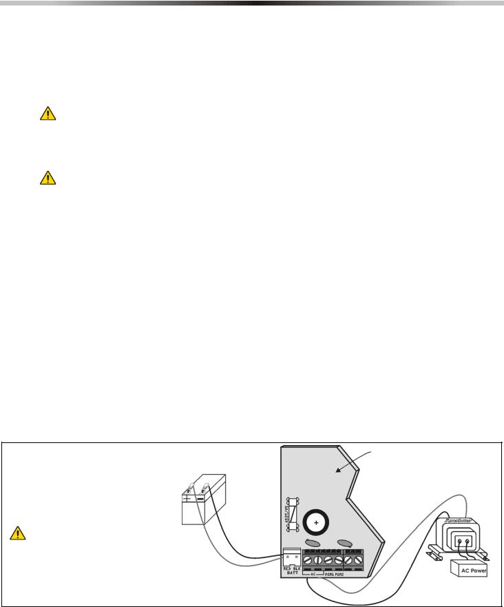
To provide power during a power loss, connect a 12Vdc 4Ah rechargeable acid/lead or gel cell backup battery as shown in Figure 1 below. Use a 7Ah battery to comply with UL fire requirements. Connect the backup battery after applying AC power. When installing, verify proper polarity as reversed connections will blow the battery fuse.
2.4.1Battery Test
If the battery is disconnected or if the battery fuse is blown, a No/Low Battery failure will appear in the keypad’s trouble display (see Trouble Display on page 60). This trouble will also appear if the battery’s capacity is too low or if the voltage drops to 10.5V or lower while the control panel is running on the backup battery. At 8.5V or lower, the panel shuts down and all outputs close.
Figure 1: AC Power and Backup Battery Connections
UL Warning:
A 12Vdc / 7Ah battery is required to comply with UL fire requirements.
Caution:
Disconnect battery before replacing the fuse.
Improper connection of the transformer may result in damage to the system.
Partial PCB view
Rechargeable Battery UL/ULC - 12Vdc / 4Ah or 7Ah
3 Reference & Installation Manual
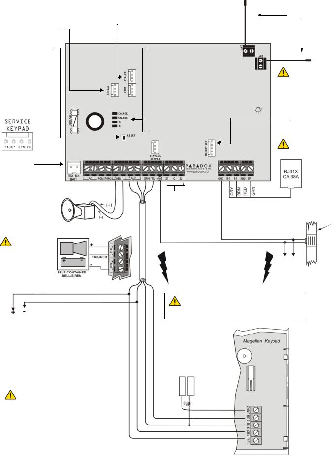
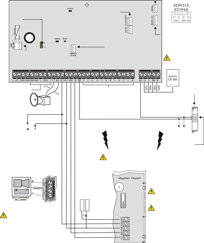
2.5MG5000 PCB Layout
Used for In-Field Firmware upgrade through a 307USB Direct Connect Interface. See Connecting to WinLoad on page 58 for details.
Press and hold the RESET button for five seconds. The STATUS LED will start flashing. Within 2 seconds of this flashing, press the reset switch again. The panel will reset to default and restart.
Four pin connector can be used for quick installation of a MG5000 keypad.
EBUS and Dialer used for VDMP3 plug-in voice module for voice reporting.
Charge LED:
Charging and Battery test LED
"STATUS" LED:
Flash once every second = Normal Flashes ON 1 second and OFF 1 second = Any trouble
Always ON = Panel is using phone line
Fast flash 6 seconds after power up = Installer lock enabled
"RX" & “TX” LED:
Flashes quickly when
receiving or transmitting RF signals from wireless devices.
Antennas
Do not cut, bend or alter the antennas and ensure that electrical wires do not cross over the antennae, as this may affect signal reception.
Paradox Memory
Key (PMC-4,
PMC5)
Disconnect telephone line before servicing.
Refer to AC Power & Backup Battery Connections on page 3.
The "BELL" output will shutdown if the current exceeds 3A.
Connection for Self-Contained Bell/Siren
The sum of the current drawn from the BELL and AUX must be
limited to 1.3A (40VA transformer strongly recommended). Exceeding this limit will overload the panel power supply and lead to complete system shutdown.
AUX Power
Refer to transformer requirements on page 3 for Aux. Power Output. To connect additional wiring to auxiliary power, use the red (+) and black (-) keypad connectors. Auxiliary power will shut down if current exceeds 1.1A. If the auxiliary output is overloaded and is shut down, you must disconnect all loads from the output for at least 10 seconds before reconnecting any load back to the auxiliary output.
This equipment must be installed and maintained by qualified service personnel only. For UL and C-UL warnings, refer to the UL and C-UL Warnings section at the back of the Reference & Installation Manual.
Refer to Single Zone
Inputs on page 12
AWG#14 single conductor solid copper wire
To provide maximum lightning protection |
To metallic |
we strongly recommend having separate |
enclosure |
earth connections for the dialer and zone |
|
ground terminals. |
|
Max. amount of keypads = 15 keypads Max. current = 700 mA
Max. distance of keypad from panel = 76m (250 feet) Max. total run of wire = 230m (750 feet)
For the keypad’s zone configurations, refer to the
Installer Quick Menu. If EOL is enabled: see section [706] option [2]. Also refer to Single Zone Inputs on page 12.
Cold water pipe grounding
Ground  clamp
clamp
Magellan / Spectra SP 4
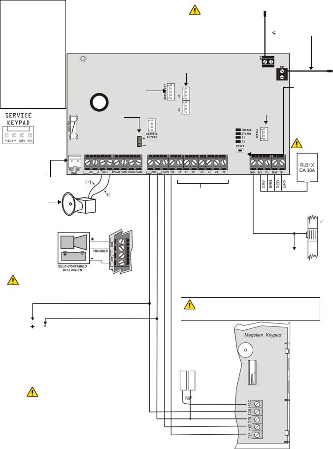
2.6MG5050 PCB Layout
Charge LED:
Charging and battery test LED
Status LED:
•Flash once every second = Normal
•Flashes ON 1 second and OFF 1 second = Any trouble
•Always ON = Panel is using phone line
•Fast flash 6 seconds after power up = Installer lock enabled
"RX" & “TX” LED:
Flashes quickly when receiving or transmitting RF signals from wireless devices.
Four pin connector can be used for quick installation of a MG5050 keypad.
Refer to AC Power & Backup Battery Connections on page 3.
The "BELL" output will shutdown if the current exceeds 3A.
Paradox Memory Key
(PMC-4, PMC5)
PGM Trigger: This jumper allows you to choose whether the solid state relay PGM (PGM4 only) is grounded (-), or gives out 12V (+).
Connection for Self-Contained Bell/Siren
Do not cut, bend or alter the antennas and ensure that electrical wires do not cross
over the antennae, as
this may affect signal  Antennas reception.
EBUS and Dialer used for VDMP3 plug-in voice module for voice reporting.
Used for In-Field Firmware upgrade through a 307USB Direct Connect Interface. See Connecting to WinLoad on page 58 for details.
Press and hold the RESET button for five seconds. The STATUS LED will start flashing. Within 2 seconds of this flashing, press the reset switch again. The panel will reset to default and restart.
Disconnect telephone line before servicing.
Refer to Single Zone
Inputs on page 12
Cold water pipe
AWG#14 single grounding conductor solid 
copper wire
 Ground clamp
To metallic enclosure
The sum of the current drawn from the BELL and AUX must be limited to 1.3A (40VA transformer strongly recommended). Exceeding this limit will overload the panel power supply and lead to complete system shutdown.
AUX Power
Refer to transformer requirements on page 3 for Aux. Power Output. To connect additional wiring to auxiliary power, use the red (+) and black (-) keypad connectors. Auxiliary power will shut down if current exceeds 1.1A. If the auxiliary output is overloaded and is shut down, you must disconnect all loads from the output for at least 10 seconds before reconnecting any load back to the auxiliary output.
This equipment must be installed and maintained by qualified service personnel only. For UL and C-UL warnings, refer to the UL and C-UL Warnings section at the back of the Reference & Installation Manual.
Max. amount of keypads = 15 keypads Max. current = 700 mA
Max. distance of keypad from panel = 76m (250 feet) Max. total run of wire = 230m (750 feet)
For the keypad’s zone configurations, refer to the
Installer Quick Menu. If EOL is enabled: see section [706] option [2]. Also refer to Single Zone Inputs on
page 12.
5 Reference & Installation Manual
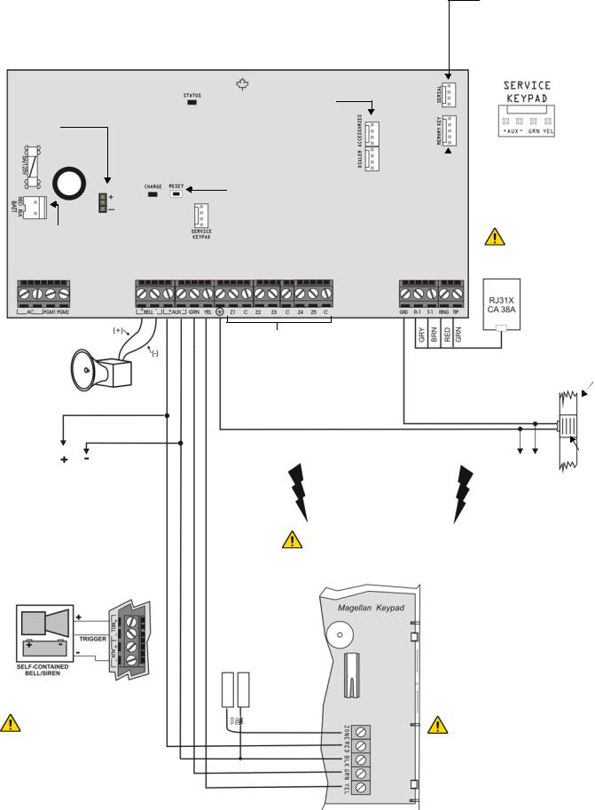
2.7SP5500 PCB Layout
Charge LED: |
Status LED: |
|
Charging and battery test LED |
• Flash once every second = Normal |
|
|
• Flashes ON 1 second and OFF 1 second = Any trouble |
|
|
• |
Always ON = Panel is using phone line |
|
• |
Fast flash 6 seconds after power up = Installer lock enabled |
|
|
|
PGM +/- trigger not supported by the SP5500
Refer to AC Power & Backup Battery Connections on page 3.
EBUS and Dialer used for VDMP3 plug-in voice module for voice reporting.
Press and hold the RESET button for five seconds. The STATUS LED will start flashing. Within 2 seconds of this flashing, press the reset switch again. The panel will reset to default and restart.
Used for In-Field Firmware upgrade through a 307USB Direct Connect Interface. See Connecting to WinLoad on page 59 for details.
Four pin connector can be used for quick installation of a SP5500 keypad.
 Paradox Memory Key
(PMC-4, PMC5)
Disconnect telephone line before servicing.
The "BELL" output will shutdown if the current exceeds 3A.
AUX Power
Refer to transformer requirements on page 3 for Aux. Power Output. To connect additional wiring to auxiliary power, use the red (+) and black (-) keypad connectors. Auxiliary power will shut down if current exceeds 1.1A. If the auxiliary output is overloaded and is shut down, you must disconnect all loads from the output for at least 10 seconds before reconnecting any load back to the auxiliary output.
Connection for Self-Contained Bell/Siren
Refer to Single Zone
Inputs on page 12
|
Cold water |
|
|
pipe |
|
|
grounding |
|
AWG#14 single |
|
|
conductor solid |
|
|
copper wire |
|
|
To metallic |
Ground |
|
clamp |
||
enclosure |
||
To provide maximum lightning |
|
|
protection we strongly recommend |
|
|
having separate earth connections |
|
|
for the dialer and zone ground |
|
|
terminals. |
|
Max. amount of keypads = 15 keypads
Max. current = 700 mA
Max. distance of keypad from panel = 76m (250 feet)
Max. total run of wire = 230m (750 feet)
For the keypad’s zone |
For the keypad’s zone |
configurations, refer to the |
|
Installer Quick Menu. If |
configurations, refer to the |
EOL is enabled: see |
Installer Quick Menu. If EOL |
section [706] option [2]. |
is enabled: see section [706] |
Also refer to Single Zone |
option [2]. Also refer to Keypad |
Inputs on page 12. |
Zone Connections on page 12. |
The sum of the current drawn from the BELL and AUX must be limited to 1.3A (40VA transformer strongly recommended). Exceeding this limit will overload the panel power supply and lead to complete system shutdown.
This equipment must be installed and maintained by qualified service personnel only.
For UL and C-UL warnings, refer to the UL and C-UL Warnings section at the back of the Reference & Installation Manual.
Magellan / Spectra SP 6
2.8SP6000 PCB Layout
Charge LED: |
|
|
Charging and battery test LED |
|
|
Status LED: |
Used for In-Field Firmware |
|
• Flash once every second = Normal |
||
• Flashes ON 1 second and OFF 1 second = Any trouble |
upgrade through a 307USB |
|
• Always ON = Panel is using phone line |
Direct Connect Interface. See |
|
• Fast flash 6 seconds after power up = Installer lock enabled |
Connecting to WinLoad on |
|
|
page 59 for details. |
|
|
|
|
PGM Trigger: This jumper allows you to choose whether the solid state relay PGMs are grounded (-), or give out 12V (+).
Refer to AC Power & Backup Battery Connections on page 3.
EBUS and Dialer used for VDMP3 plug-in voice module for voice reporting.
Press and hold the RESET button for five seconds. The STATUS LED will start flashing. Within 2 seconds of this flashing, press the reset switch again. The panel will reset to default and restart.
PGM3,PGM4, and the |
Refer to Single Zone |
alarm relay are optional. |
Inputs on page 12
Four pin connector can be used for quick installation of a SP6000 keypad.
Paradox Memory Key
(PMC-4, PMC5)
Disconnect telephone line before servicing.
Cold water pipe grounding
The "BELL" output will shutdown if the current exceeds 3A.
AUX Power
Refer to transformer requirements on page 3 for Aux. Power Output. To connect additional wiring to auxiliary power, use the red (+) and black (-) keypad connectors. Auxiliary power will shut down if current exceeds 1.1A. If the auxiliary output is overloaded and is shut down, you must disconnect all loads from the output for at least 10 seconds before reconnecting any load back to the auxiliary output.
Connection for Self-Contained Bell/Siren
The sum of the current drawn from the BELL and AUX must be limited to 1.3A (40VA transformer strongly recommended). Exceeding this limit will overload the panel power supply and lead to complete system shutdown.
|
AWG#14 single |
|
|
conductor solid |
|
|
copper wire |
|
|
To metallic |
|
To provide maximum lightning |
enclosure |
|
protection we strongly recommend |
|
|
having separate earth connections |
Ground |
|
for the dialer and zone ground |
||
clamp |
||
terminals. |
||
|
Max. amount of keypads = 15 keypads Max. current = 700 mA
Max. distance of keypad from panel = 76m (250 feet) Max. total run of wire = 230m (750 feet)
For the keypad’s zone configurations, refer to the
Installer Quick Menu. If EOL is enabled: see section [706] option [2]. Also refer to Keypad Zone Connections on page 12.
When using an SP6000 panel in conjunction with an MG-RTX3, all MG32LED and MG10LEDV/H keypads must be versions 2.0 or higher.
This equipment must be installed and maintained by qualified service personnel only.
For UL and C-UL warnings, refer to the UL and C-UL Warnings section at the back of the Reference & Installation
7 Reference & Installation Manual
2.9SP7000 PCB Layout
Charge LED:
Charging and battery test LED
Status LED:
•Flash once every second = Normal
•Flashes ON 1 second and OFF 1 second = Any trouble
•Always ON = Panel is using phone line
•Fast flash 6 seconds after power up = Installer lock enabled
Press and hold the RESET button for five seconds. The STATUS LED will start flashing. Within 2 seconds of this flashing, press the reset switch again. The panel will reset to default and restart.
PGM Trigger: This jumper allows you to choose whether the solid state relay PGMs are grounded (-), or give out 12V (+).
Refer to AC Power & Backup Battery Connections on page 3.
Used for In-Field Firmware upgrade through a 307USB Direct Connect Interface. See Connecting to WinLoad on page 59 for details.
EBUS and Dialer used for VDMP3 plug-in voice module for voice reporting.
Upper Inputs = Zones 9 to 16 Lower Inputs = Zones 1 to 8
Four pin connector can be used for quick installation of a SP7000 keypad.
Paradox Memory Key
(PMC-4, PMC5)
Disconnect telephone line before servicing.
The "BELL" output will shutdown if the current exceeds 3A.
AUX Power
Refer to transformer requirements on page 3 for Aux. Power Output. To connect additional wiring to auxiliary power, use the red (+) and black (-) keypad connectors. Auxiliary power will shut down if current exceeds 1.1A. If the auxiliary output is overloaded and is shut down, you must disconnect all loads from the output for at least 10 seconds before reconnecting any load back to the auxiliary output.
Connection for Self-Contained Bell/Siren
The sum of the current drawn from the BELL and AUX must be limited to 1.3A (40VA transformer strongly recommended). Exceeding this limit will overload the panel power supply and lead to complete system shutdown.
Refer to Single Zone
Inputs on page 12
Cold water pipe grounding
AWG#14 single conductor solid copper wire
For the keypad’s zone configurations, refer to the
Installer Quick Menu. If EOL is enabled: see section [706] option [2]. Also refer to Keypad Zone Connections on page 12.
|
To metallic |
Ground |
|
To provide maximum lightning |
clamp |
||
enclosure |
|||
protection we strongly recommend |
|
||
|
|
||
having separate earth connections |
|
|
|
for the dialer and zone ground |
|
|
|
terminals. |
|
|
Max. amount of keypads = 15 keypads
Max. current = 700 mA
Max. distance of keypad from panel = 76m (250 feet)
Max. total run of wire = 230m (750 feet)
For the keypad’s zone configurations, refer to the
Installer Quick Menu. If EOL is enabled: see section [706] option [2]. Also refer to Keypad Zone Connections on page 12.
This equipment must be installed and maintained by qualified service personnel only.
For UL and C-UL warnings, refer to the UL and C-UL Warnings section at the back of the Reference & Installation Manual.
Magellan / Spectra SP 8
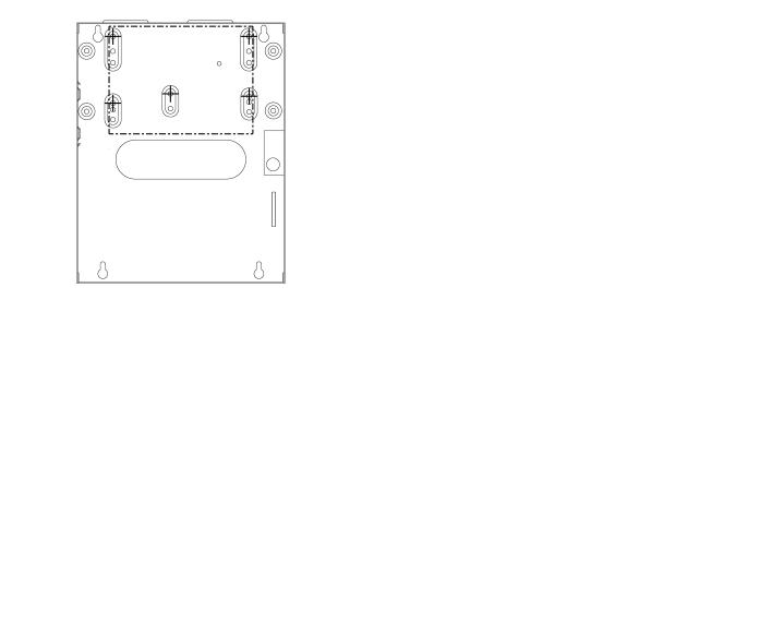
2.10Metal Box Installation
The crosses and dotted line represent the mounting location. If you need specific dimensions, contact Paradox Distributor Support. For UL recommended installation for the MG5000 only, place the PCB one notch lower than the mounting location.
MG5000 (8x10”) |
MG5000 (11x11”) |
MG5050 (11x11”)
9 Reference & Installation Manual
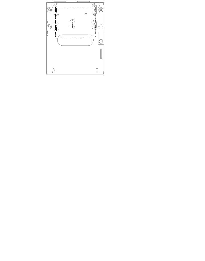
SP5500 (8x10”)
SP6000 (11x11”)
SP7000 (11x11”)
Magellan / Spectra SP 10

2.11Auxiliary Power Terminals
The auxiliary power supply terminals can be used to power motion detectors, keypads and other modules or accessories in the security system. A fuseless circuit protects the power supply against current overload and automatically shuts down if the current exceeds 1.1A. If this occurs, the Maximum Auxiliary Current failure will appear in the keypad’s trouble display (see Trouble Display on page 60). Therefore, the combined current consumption of devices connected to the auxiliary power supply should not exceed 700mA. If the auxiliary output is overloaded and is shut down, you must disconnect all loads from the output for at least 10 seconds before reconnecting any load back to the auxiliary output.
2.12Telephone Line Connection
In order to report system events to the monitoring station, you must connect the incoming telephone company wires into the TIP and RING connections of the control panel and then run the wires from T1 and R1 to the telephone or telephone system as shown in PCB Layouts for each respective panel.
2.13Bell Output Connection
The BELL+ and BELLterminals power bells, sirens and other warning devices requiring a steady voltage output during an alarm. The bell output supplies 12Vdc upon alarm and can support one 30-watt or two 20-watt sirens. The bell output uses a fuseless circuit and will automatically shut down if the current exceeds 3A. When this occurs the Maximum Bell Current failure will only appear in the keypad’s trouble display (see Trouble Display on page 60) during an alarm. If the load on the BELL terminals returns to normal, the control panel will re-instate power to the BELL terminals during the next alarm. When connecting sirens, please verify correct polarity. Connect the positive lead to the BELL+ terminal and the negative lead to the BELLterminal of the control panel as shown in PCB Layouts for each respective panel.
If the BELL output is not being used, the Bell Disconnected failure will remain in the keypad’s trouble display (see Trouble Display on page 60). To avoid this connect a 1KΩ resistor across the BELL terminals.
For connection of a self-contained bell/siren, see PCB Layouts for each respective panel.
2.14Programmable Output Connections
When a specific event occurs in the system, a PGM can reset smoke detectors, activate strobe lights, open/close garage doors and much more.
2.14.1PGMs
The control panels include two/four on-board programmable outputs (PGMs). For details on how to program PGMs, see Programmable Outputs on page 53. PGM1 and PGM2 can support up to 150mA. The PGMs are limited by the power source being used. If powered by:
•The AUX terminals. The current consumption of the AUX terminals cannot exceed 700mA. Therefore, whatever devices are connected to the AUX terminals (i.e. modules and PGMs) cannot exceed 700mA combined. For example, if there are six modules connected to the AUX terminals that are using 600mA and you wish to power the PGM using the AUX terminals, the PGM’s current consumption cannot exceed 100mA.
•An external power supply. If using an external power supply, the current consumption cannot exceed 150mA for PGM1 and PGM2. If the external power supply’s current consumption limit is less than that of the PGM it is connected to, than the current consumption will not exceed the power supply’s current limit.
UL Note: The AUX terminals cannot exceed 200mA for UL installations.
Figure 2: Relay and PGM Connections
11 Reference & Installation Manual
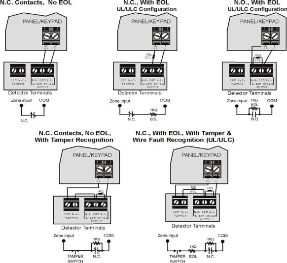
2.15Single Zone Inputs
Detection devices such as motion detectors and door contacts are connected to the control panel's zone input terminals. Figure 3 demonstrates single zone input terminal connections recognized by the panel. Once connected, the associated zone's parameters must be defined.
Figure 3: Single Zone Input Connections
Magellan / Spectra SP 12
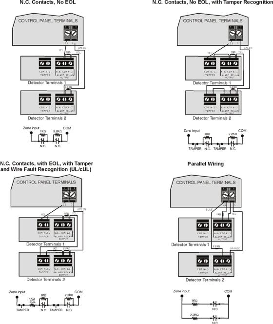
2.16Advanced Technology Zone (ATZ) Connections
The ATZ feature is a software oriented feature that enables two detection devices to be installed per hardwired input terminal. Each detection device has its own zone, displays its zone status on the keypad and sends its own alarm codes. Fire zones cannot be doubled.
Figure 4: Advanced Technology Zone Connections
13 Reference & Installation Manual
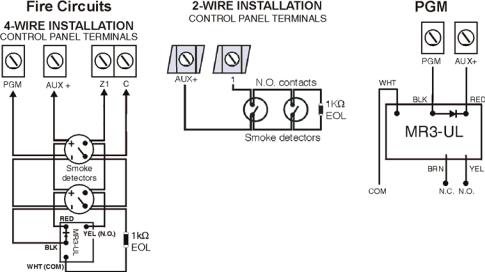
2.17Fire Circuits
When a zone is programmed as a fire zone, the zone becomes normally open and requires an EOL resistor. If a line short occurs or if the smoke detector becomes active, whether the system is armed or disarmed, the control panel will generate an alarm. If a trouble occurs on a fire zone, the Fire Loop Trouble will appear in the keypad’s trouble display (see Trouble Display on page 60) and the control panel can transmit the Fire Loop Trouble report, if programmed, in section [866].
Figure 5: Fire Circuits
2.17.14-Wire and 2-Wire Installation:
For 4-wire installation, program the Activation Event so that the smoke detectors can be reset by pressing the [CLEAR]
+ [ENTER] keys for three seconds. See Event Group # 6 in the Event Description list in the programming guide.
For 2-wire smoke detector installation, connect the 2-wire smoke detectors. If a line short occurs or the smoke detector activates, whether the system is disarmed, the control panel will generate an alarm. If the line is open, the “Zone Fault” trouble indication appears on the trouble display and the report code is sent to the monitoring station, if programmed. To reset 2-wire smoke detectors, press the [CLEAR] + [ENTER] keys for three seconds.
Magellan / Spectra SP 14

Part 3: Programming Methods
3.1WinLoad Software for Windows
Program the control panels remotely or on-site using the WinLoad Software (V2.80 or higher) for Windows®. For more information, contact your local Paradox Distributor or visit our web site at paradox.com. If you are using the WinLoad software, you must program the features (see Settings for WinLoad Software on page 58). Update the panel’s firmware by connecting it to a PC via a 307 Direct Connect Interface and then using the Winload software. (Not investigated by UL).
3.2Programming Using a Keypad
Use the supplied programming guide to keep track of which sections were programmed and how. We recommend you read the entire manual before you begin programming.
How Do I Enter Programming Mode?
1)Press [ENTER]
2)Enter your [INSTALLER CODE] (default: 0000 / 000000) or [MAINTENANCE CODE] (empty by default)
3)Enter 3-digit [SECTION] you wish to program
4)Enter required [DATA]
3.2.1Single Digit Data Entry Method (Decimal and Hexadecimal)
Single Digit Data Entry is used in all sections except those specified in the Feature Select Programming Method (below). After entering Programming Mode as described in the shaded box above, some sections will require that you enter Decimal values from 000 to 255. Other sections will require that you enter Hexadecimal values from 0 to F. The required data will be clearly indicated in this manual as well as in the programming guide. When entering the final digit in a section, the control panel will automatically save and advance to the next section. Except sections 001 to 032, after entering the first three digits the control panel will switch to Feature Select Programming. For phone number programming, press [ENTER] to save the data.
Table 2: Decimal and Hexadecimal Programming Table
Value or Action |
What Do I |
What Do I See? |
||
|
|
|||
Press? |
32-zone LED |
10-zone LED |
||
|
||||
|
|
|
|
|
Value 0 / Replace Current Digit |
[SLEEP] |
Erase digit and remain in section |
Erase digit and remain in |
|
with 0 |
|
|
section |
|
|
|
|
|
|
Values 1 to 9 |
[1] to [9] |
Zone 1 to 9 |
[1] to [9] |
|
|
|
|
|
|
A (hex only) |
[0] |
Zone 10 |
[0] |
|
B (hex only) |
[OFF] |
Zone 11 |
[OFF] |
|
C (hex only) |
[BYP] |
Zone 12 |
[BYP] |
|
|
|
|
|
|
D (hex only) |
[MEM] |
Zone 13 |
[MEM] |
|
E (hex only) |
[TBL] |
Zone 14 |
[TBL] |
|
F (hex only) |
[ ] |
Zone 15 |
[ ] |
|
|
|
|
|
|
Exit Without Saving |
[CLEAR] |
ARM & STAY LED flash |
ARM & STAY LED flash |
|
|
|
|
|
|
Save Data (hex only) |
[ENTER] |
Advances to the next section |
Advances to the next section |
|
|
|
|
|
|
3.2.2Feature Select Programming Method
After entering certain sections, eight options will be displayed where each option from [1] to [8] represents a specific feature. Press the key corresponding to the desired option. This means the option is ON. Press the key again to remove the digit, thereby, turning OFF the option. When the options are set, press the [ENTER] key to save and advance to the next section.
15 Reference & Installation Manual
3.2.3Data Display Mode (except MG32LCD)
In the Data Display Mode you can view the programmed contents of each section one digit at a time.
Figure 6: Data Display Mode
To access the Data Display Mode, press the [ENTER] key after entering a section and before entering any data. The four LEDs as indicated below will begin to flash indicating that you are in the Data Display Mode.
Each time the [ENTER] key is pressed, the keypad will display the next digit in the current section and will continue through all the following sections one digit at a time without changing the programmed values. Not available for sections using the Multiple Feature Select Method. Press the [CLEAR] key at any time to exit the Data Display Mode.
3.3Configuring the Keypad Zone Number
How Do I Configure The Keypad?
Press [ENTER]
Enter your [INSTALLER CODE] (default: 0000 / 000000) or [MAINTENANCE CODE] (empty by default)
Press [ ] and hold for three seconds
Enter the desired zone number key (MG32LED/MG32LCD: 2-digit entry 01 to 32, MG10LEDV/H: 1-digit entry 1 to 0(10)) Press [ENTER] to save and exit programming mode
Press [CLEAR] to erase data without saving
Press [CLEAR]+[CLEAR] to exit programming mode without saving
PLEASE NOTE: After five minutes, the keypad exits programming mode.
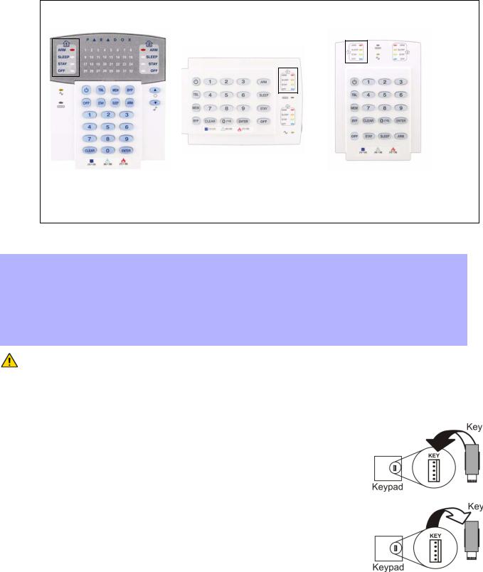
3.4Programming Using A Paradox Memory Key*
Copy the sections of one control panel into the Paradox Memory Key (PMC-4/PMC5). Then copy the contents of the Memory Key into as many control panels as needed. Each panel is programmed in less than 3 seconds.
Download to DESTINATION Control Panel or module
1)Remove AC and battery power from the control panel.
2)Place the Memory Key on the serial connector labeled MEMORY KEY of the Control Panel that is to receive the contents of the Memory Key.
3)Reapply AC and battery power.
4)In Installer Programming Mode, enter section [970], the keypad emits a confirmation beep.
5)When the keypad emits a second confirmation beep, remove the Memory Key.
Copy to Memory Key from SOURCE Control Panel or module
1)Remove AC and battery power from the control panel.
2)Place Memory Key on the serial connector labeled MEMORY KEY of the Control Panel that you want to copy. Make sure the write protect jumper of the Memory Key is on.
3)Reapply AC and battery power.
4)In Installer Programming Mode, enter section [975]. The keypad emits a confirmation beep.
5)After the keypad emits a second confirmation beep, remove the Memory Key. Remove the
Memory Key’s jumper if you do not wish to accidentally overwrite its contents.
* Not investigated by UL
Magellan / Spectra SP 16
|
|
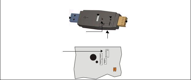
Figure 7: Paradox Memory Key |
||||||
|
|
|
|
|
|
|
|
|
Blue LED flashes only |
|
|
|
|
|
|
|
|
during transfer between |
|
|
|
|
|
|
Prevents overwriting |
|
the key and the PC. |
|
|
|
|
|
|
content of key. |
|
Connection to |
|
|
|
|
|
|
|
|
|
|
|
|
|
|
|
||
|
|
|
|
|
|
|
||
|
|
|
|
|
|
|
||
USB Com Port. |
|
|
|
|
|
|
Connection to |
|
|
|
|
|
|
|
|||
|
|
|
|
|
|
|
|
module or panel. |
Copy and download content of the key.
Lock Switch
Partial view of control panel
Insert Paradox Memory Key onto the ‘MEMKEY’
connector.
17 Reference & Installation Manual

Part 4: LCD Keypad Labels
4.1Input Keys
|
Special Function Keys |
|
Alphanumeric Key Input |
|
Key |
Function |
|
[1] |
A / B / C |
[STAY] |
Insert space |
|
[2] |
D / E / F |
[SLEEP] |
Delete |
|
[3] |
G / H / I |
[ARM] |
Delete whole entry |
|
[4] |
J / K / L |
[OFF] |
Toggle numeric/alphanumeric keys |
|
[5] |
M / N / O |
[BYP] |
Toggle lower case/upper case |
|
[6] |
P / Q / R |
[MEM] |
Special characters |
|
[7] |
S / T / U |
|
|
|
[8] |
V / W / X |
|
|
|
[9] |
Y / Z |
4.2Label Sections
Label Sections
[181] to [212] |
32 Zone Labels |
[341] to [356] |
16 PGM Labels |
[511] to [542] |
32 User Labels |
[771] to [772] |
2 Partition Labels |
[568] to [569] |
2 Wireless Labels |
[599] to [606] |
8 Wireless Keypads |
[781] to [795] 15 Bus Modules Labels
4.3Special Characters and Keypad Letter Assignment
Polish / Hungarian / Turkish Special Character Catalogue |
Special Character Catalogue |
|||||||||
|
|
|
|
|
|
|
|
|
|
|
|
Polish |
001 |
002 |
003 |
004 |
005 |
006 |
007 |
|
|
|
|
|
|
|
|
|
|
|
|
|
|
|
|
|
|
|
|
|
|
|
|
|
Hungarian |
001 |
002 |
003 |
|
|
|
|
|
|
|
|
|
|
|
|
|
|
|
|
|
|
|
|
|
|
|
|
|
|
|
|
|
Turkish |
001 |
|
|
|
|
|
|
|
|
|
|
|
|
|
|
|
|
|
|
|
|
|
|
|
|
|
|
|
|
|
|
Magellan / Spectra SP 18
Loading...