


MAGELLAN MG5000
Table of contents
 Loading...
32-Zone Wireless Transceiver Security Systems
MG5000 V3.2
MG5050 V3.2
5- to 32-Zone Expandable Security Systems
SP5500 V3.2
SP6000 V3.2
SP7000 V3.2
Always Armed,
Never Disarmed
Programming Guide
PARADOX.COM


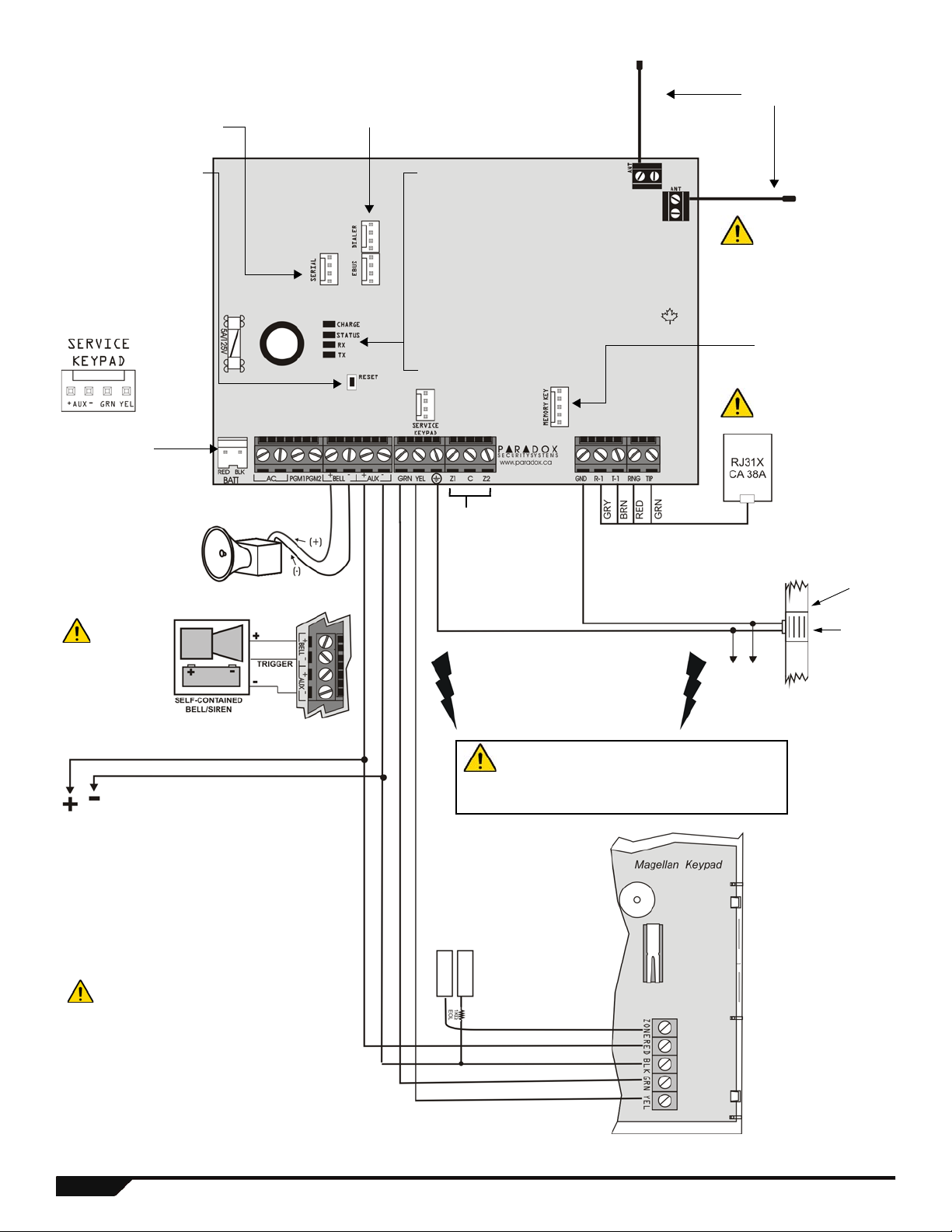
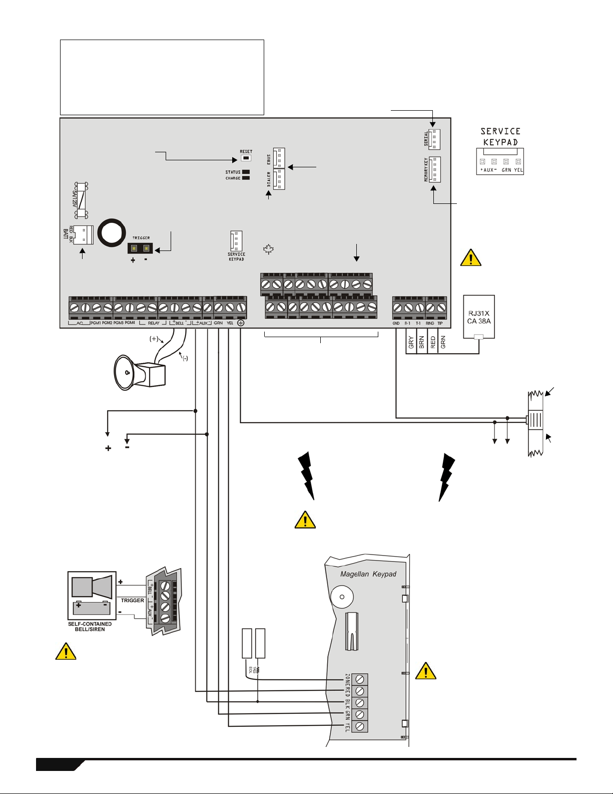
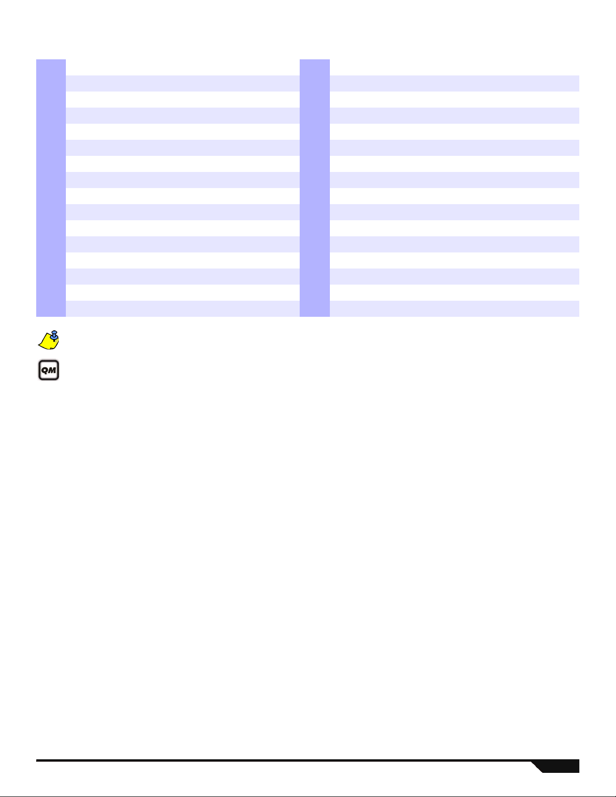
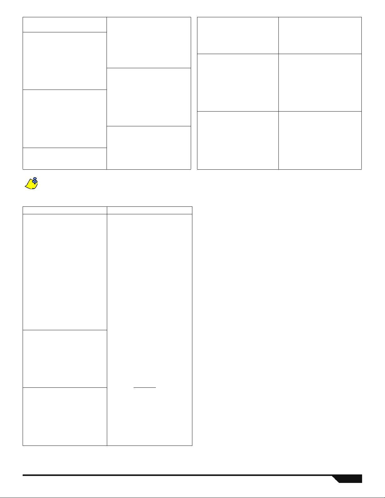
MG5000 PCB Layout
Refer to Single Zone
Inputs on page 59
Refer to AC Power
& Backup Battery
Connections on
page 61.
For the keypad’s zone
configurations, refer to
the Installer Quick
Menu. If EOL is enabled:
see section [706] option
[2]. Also refer to Keypad
Zone Connections on
page 59.
AUX Power
Refer to transformer requirements on p age61 for Aux.
Power Output. To connect additional wiring to auxiliary
power, use the red (+) and black (-) keypad connectors.
Auxiliary power will shut down if current exceeds 1.1A. If the
auxiliary output is overloaded and is shut down, you must
disconnect all loads from the output for at least 10 seconds
before reconnecting any load back to the auxiliary output.
To provide maximum lightning protection
we strongly recommend having separate
earth connections for the dialer and zone
ground terminals.
To metallic
enclosure
Ground
clamp
AWG#14 single
conductor solid
copper wire
Cold water
pipe
grounding
The "
BELL" output will shutdown if
the current exceeds 3A.
Disconnect telephone
line before servicing.
Four pin connector
can be used for
quick installation of a
keypad.
Do not cut, bend or alter
the antennas and ensure
that electrical wires do
not cross over the
antennae, as this may
affect signal reception.
Paradox Memory Key
(PMC-4 PMC-5)
Antennas
"RX" & “TX” LED:
Flashes quickly when
receiving or transmitting RF signals
from wireless devices.
"STATUS" LED:
Flash once every second = Normal
Flashes ON 1 second and OFF 1 second =
Any trouble
Always ON = Panel is using phone line
Fast flash 6 seconds after power up = Installer
lock enabled
This equipment must be installed and maintained
by qualified service personnel only.
For UL and C-UL warnings, refer to the UL and
C-UL Warnings section at the back of the
Reference & Installation Manual.
Used for In-Field Firmware upgrade
through a 307USB Direct Connect
Interface. See Connecting to
WinLoad on page 62 for details.
EBUS and Dialer used with:
VDMP3 plug-in voice module for voice reporting
PCS100 GSM communicator module
Press and hold the RESET
button for five seconds. The
STATUS LED will start
flashing. Within 2 seconds
of this flashing, press the
reset switch again. The
panel will reset to default
and restart.
The sum of the
current drawn
from the BELL
and AUX must be
limited to 1.3A (40VA
transformer strongly
recommended).
Exceeding this limit will
overload the panel
power supply and lead
to complete system
shutdown.
Connection for Self-Contained Bell/Siren
Max. amount of keypads = 15 keypads
Max. aux. current = 700 mA
Max. distance of keypad from panel = 76m (250 feet)
Max. total run of wire = 230m (750 feet)
Charge LED:
Charging and Battery test LED
* If EOL is enabled: see section
[706] option [2]. For the keypad’s
zone configurations, refer to
Installer Quick Menu on page 65.
Also refer to keypad zone
connections on page 59.
1 Programming Guide
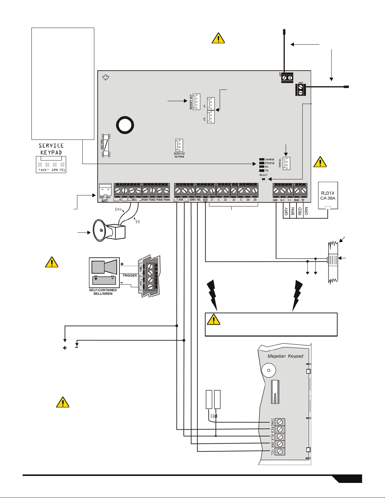
MG5050 PCB Layout
Used for In-Field Firmware upgrade
through a 307USB Direct Connect
Interface. See Connecting to
WinLoad on page 62 for details.
Antennas
Do not cut, bend or
alter the antennas and
ensure that electrical
wires do not cross
over the antennae, as
this may affect signal
reception.
Four pin connector can
be used for quick
installation of a keypad.
Refer to AC Power
& Backup Battery
Connections on
page 61.
Paradox Memory Key
(PMC-4, PMC-5)
LEDs
Charge LED:
Charging and battery test
LED
Status LED:
• Flash once every second =
Normal
• Flashes ON 1 second and
OFF 1 second = Any trouble
• Always ON = Panel is
using phone line
• Fast flash 6 seconds after
power up = Installer lock
enabled
"RX" & “TX” LED:
Flashes quickly when
receiving or transmitting RF
signals from wireless
devices.
To metallic
enclosure
Ground
clamp
AWG#14 single
conductor solid
copper wire
Cold water
pipe
grounding
To provide maximum lightning
protection we strongly recommend
having separate earth connections
for the dialer and zone ground
terminals.
The "
BELL" output will
shutdown if the current
exceeds 3A.
Refer to Single Zone
Inputs on page 59
Max. amount of keypads = 15 keypads
Max. aux. current = 700 mA
Max. distance of keypad from panel = 76m (250 feet)
Max. total run of wire = 230m (750 feet)
Disconnect telephone
line before servicing.
AUX Power
Refer to transformer requirements on page61 for Aux.
Power Output. To connect additional wiring to auxiliary
power, use the red (+) and black (-) keypad connectors.
Auxiliary power will shut down if current exceeds 1.1A. If the
auxiliary output is overloaded and is shut down, you must
disconnect all loads from the output fo r at least 10 seconds
before reconnecting any load back to the auxiliary output.
This equipment must be installed and
maintained by qualified service personnel only.
For UL and C-UL warnings, refer to the UL and
C-UL Warnings section at the back of the
Reference & Installation Manual.
The sum of the
current drawn
from the BELL and AUX
must be limited to 1.3A
(40VA transformer
strongly recommended).
Exceeding this limit will
overload the panel power
supply and lead to
complete system
shutdown.
Connection for Self-Contained Bell/Siren
For the keypad’s zone
configurations, refer to
the Installer Quick
Menu. If EOL is
enabled: see section
[706] option [2]. Also
refer to Keypad Zone
Connections on
page 59.
Press and hold the
RESET button for five
seconds. The STATUS
LED will start flashing.
Within 2 seconds of
this flashing, press the
reset switch again. The
panel will reset to
default and restart.
* If EOL is enabled: see section
[706] option [2]. For the
keypad’s zone configurations,
refer to Installer Quick Menu on
page 65. Als o r ef e r to keypad
zone connections on page 59.
*
Solid-state PGM
(+/- trigger on
PGM4 only.
J3 and J4 used with:
VDMP3 plug-in voice modu l e for
voice reporting
PCS100 GSM communicator
module
Magellan / Spectra SP 2
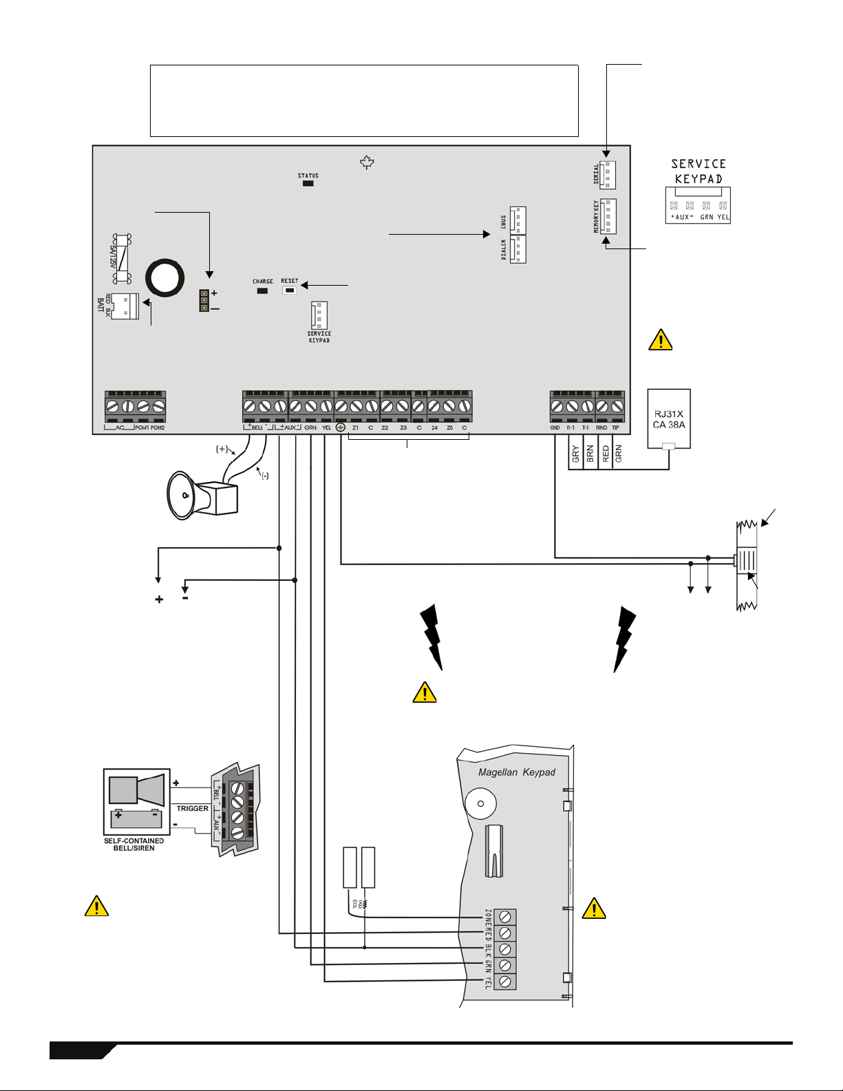
SP5500 PCB Layout
Four pin connector can be used
for quick installation of a SP5500
keypad.
Used for In-Field Firmware
upgrade through a 307USB Direct
Connect Interface. See Connecting
to WinLoad on page 62 for details.
Paradox Memory Key
(PMC-4, PMC5)
Refer to AC Power
& Backup Battery
Connections on
page 61.
The "
BELL" output will
shutdown if the current
exceeds 3A.
AUX Power
Refer to transformer requirements on page 61 for
Aux. Power Output. To connect additional wiring to
auxiliary power, use the red (+) and black (-)
keypad connectors. Auxiliary power will shut down
if current exceeds 1.1A. If the auxiliary output is
overloaded and is shut down, you must
disconnect all loads from the output for at least 10
seconds before reconnecting any load back to the
auxiliary output.
This equipment must be installed and
maintained by qualified service
personnel only.
For UL and C-UL warnings, refer to
the UL and C-UL Warnings section at
the back of the Reference &
Installation Manual.
The sum of the current drawn
from the BELL and AUX must be
limited to 1.3A (40VA transformer
strongly recommended).
Exceeding this limit will overload
the panel power supply and lead
to complete system shutdown.
Connection for Self-Contained Bell/Siren
To provide maximum lightning
protection we strongly recommend
having separate earth connections
for the dialer and zone ground
terminals.
Max. amount of keypads = 15 keypads
Max. aux. current = 700 mA
Max. distance of keypad from panel = 76m (250 feet)
Max. total run of wire = 230m (750 feet)
Disconnect telephone
line before servicing.
To metallic
enclosure
Ground
clamp
AWG#14 single
conductor solid
copper wire
Cold water
pipe
grounding
For the keypad’s zone
configurations, refer to the
Installer Quick Menu. If EOL
is enabled: see section [706]
option [2]. Also refer to Keypad
Zone Connections on page 59.
Refer to Single Zone
Inputs on page 59
PGM +/- trigger not
supported by the
SP5500
Press and hold the RESET button
for five seconds. The STATUS LED
will start flashing. Within 2 seconds
of this flashing, press the reset
switch again. The panel will reset to
default and restart.
Charge LED:
Charging and battery test LED
Status LED:
• Flash once every second = Normal
• Flashes ON 1 second and OFF 1 second = Any trouble
• Always ON = Panel is using phone line
• Fast flash 6 seconds after power up = Installer lock enabled
EBUS and Dialer used with:
VDMP3 plug-in voice module for voice reporting
PCS100 GSM communicator module
* If EOL is enabled: see
section [706] option [2].
For the keypad’s zone
configurations, refer to
Installer Quick Menu on
page 65. Also refer to
keypad zone
connections on page 59.
3 Programming Guide
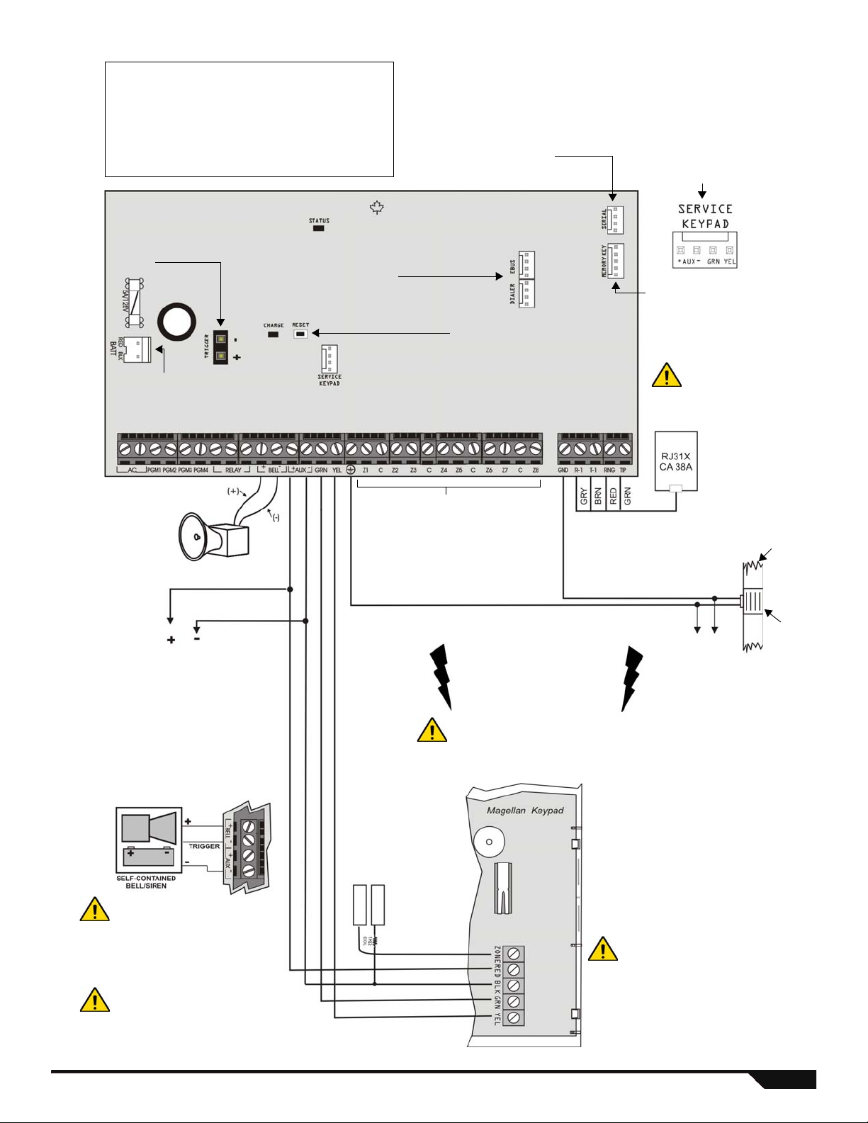
SP6000 PCB Layout
LEDs
Charge LED:
Charging and battery test LED
Status LED:
• Flash once every second = Normal
• Flashes ON 1 second and OFF 1 second = Any trouble
• Always ON = Panel is using phone line
• Fast flash 6 seconds after power up = Installer lock enabled
Four pin connector can
be used for quick
installation of a keypad.
Used for In-Field Firmware
upgrade through a 307USB
Direct Connect Interface. See
Connecting to WinLoad on
page 62 for details.
Paradox Memory Key
(PMC-4, PMC-5)
Refer to AC Power
& Backup Battery
Connections on
page 61.
The "
BELL" output will
shutdown if the current
exceeds 3A.
AUX Power
Refer to transformer requirements on page 61 for
Aux. Power Output. To connect additional wiring to
auxiliary power, use the red (+) and black (-)
keypad connectors. Auxiliary power will shut down
if current exceeds 1.1A. If the auxiliary output is
overloaded and is shut down, you must
disconnect all loads from the output for at least 10
seconds before reconnecting any load back to the
auxiliary output.
This equipment must be installed and
maintained by qualified service
personnel only.
For UL and C-UL warnings, refer to the
UL and C-UL Warnings section at the
back of the Reference & Installation
Manual.
The sum of the current drawn
from the BELL and AUX must be
limited to 1.3A (40VA transformer
strongly recommended).
Exceeding this limit will overload
the panel power supply and lead
to complete system shutdown.
Connection for Self-Contained Bell/Siren
To provide maximum lightning
protection we strongly recommend
having separate earth connections
for the dialer and zone ground
terminals.
Max. amount of keypads = 15 keypads
Max. aux. current = 700 mA
Max. distance of keypad from panel = 76m (250 feet)
Max. total run of wire = 230m (750 feet)
Disconnect telephone
line before servicing.
To metallic
enclosure
Ground
clamp
AWG#14 single
conductor solid
copper wire
Cold water
pipe
grounding
For the keypad’s zone configurations, refer to the
Installer Quick Menu. If EOL is enabled: see
section [706] option [2]. Also refer to Keypad Zone
Connections on page 59.
Refer to Single Zone
Inputs on page 59
PGM Trigger: This
jumper allows you to
choose whether the solid
state relay PGMs are
grounded (-), or give out
12V (+).
Press and hold the
RESET button for five
seconds. The STATUS
LED will start flashing.
Within 2 seconds of
this flashing, press the
reset switch again. The
panel will reset to
default and restart.
When using an SP6000 panel in
conjunction with an RTX3, all K32
and K10V/H keypads must be
versions 2.0 or higher.
* If EOL is enabled: see
section [706] option [2].
For the keypad’s zone
configurations, refer to
Installer Quick Menu on
page 65. Also refer to
keypad zone
connections on page 59.
*
EBUS and Dialer used with:
VDMP3 plug-in voice module for voice reporting
PCS100 GSM communicator module
Magellan / Spectra SP 4
SP7000 PCB Layout
LEDs
Charge LED:
Charging and battery test LED
Status LED:
• Flash once every second = Normal
• Flashes ON 1 second and OFF 1 second = Any trouble
• Always ON = Panel is using phone line
• Fast flash 6 seconds after power up = Installer lock enabled
Four pin connector can
be used for quick
installation of a keypad.
Used for In-Field Firmware
upgrade through a 307USB
Direct Connect Interface. See
Connecting to WinLoad on
page 62 for details.
Paradox Memory Key
(PMC-4, PMC-5)
Refer to AC Power
& Backup Battery
Connections on
page 61.
The "
BELL" output will
shutdown if the current
exceeds 3A.
AUX Power
Refer to transformer requirements on page61
for Aux. Power Output. To connect additional
wiring to auxiliary power, use the red (+) and
black (-) keypad connectors. Auxiliary power
will shut down if current exceeds 1.1A. If the
auxiliary output is overloaded and is shut down,
you must disconnect all loads from the output
for at least 10 seconds before reconnecting any
load back to the auxiliary output.
This equipment must be installed and
maintained by qualified service
personnel only.
For UL and C-UL warnings, refer to the
UL and C-UL Warnings section at the
back of the Reference & Installation
Manual.
The sum of the current drawn from
the BELL and AUX must be limited
to 1.3A (40VA transformer strongly
recommended). Exceeding this
limit will overload the panel power
supply and lead to complete
system shutdown.
Connection for Self-Contained Bell/Siren
To provide maximum lightning
protection we strongly recommend
having separate earth connections
for the dialer and zone ground
terminals.
Max. amount of keypads = 15 keypads
Max. aux. current = 700 mA
Max. distance of keypad from panel = 76m (250 feet)
Max. total run of wire = 230m (750 feet)
Disconnect telephone
line before servicing.
To metallic
enclosure
Ground
clamp
AWG#14 single
conductor solid
copper wire
Cold water
pipe
grounding
For the keypad’s zone configurations, refer to the
Installer Quick Menu. If EOL is enabled: see
section [706] option [2]. Also refer to Keypad Zone
Connections on page 59.
Refer to Single Zone
Inputs on page 59
PGM Trigger: This jumper allows you
to choose whether the solid state
relay PGMs are grounded (-), or give
out 12V (+).
Upper Inputs = Zones 9 to 16
Lower Inputs = Zones 1 to 8
Press and hold the RESET button for five seconds. The
STATUS LED will start flashing. Within 2 seconds of this
flashing, press the reset switch again. The panel will
reset to default and restart.
* If EOL is enabled: see
section [706] option [2].
For the keypad’s zone
configurations, refer to
Installer Quick Menu on
page 65. Also refer to
keypad zone
connections on page 59.
*
Z1 Z2 Z3 Z4 C Z5 Z6 Z7 Z8 C
Z9 Z10 Z11 Z12 C Z13 Z14 Z15 Z16 C
EBUS and Dialer used with:
VDMP3 plug-in voice module
for voice reporting
PCS100 GSM communicator
module
May be labeled
ADM2 on some
panels
5 Programming Guide
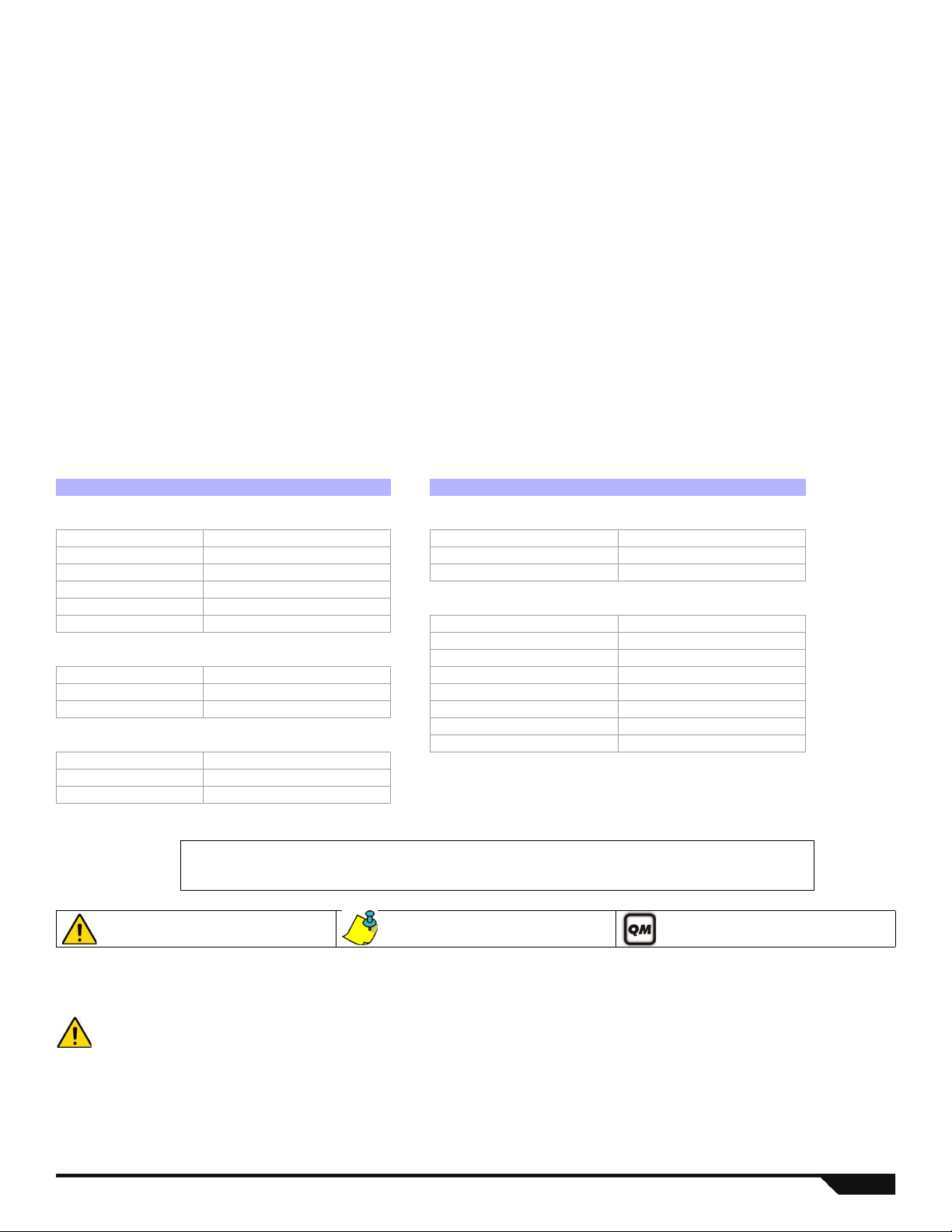
Table of Contents
Table of Contents ... ... .... ... ... ... .... ... ... ... .......................... 6
Entering Programming Mode ........................................ 6
Codes and Panel Reset ................................................ 7
System Overview .......................................................... 7
User Programming ..................... ... ... ... ... .... ... ... ... .... ... ... 8
System Planning ......................................................... 13
Wireless Keypad Planning .......................................... 14
Wireless System Planning ........................................... 15
Daylight Savings Programming ............................... .... 21
Keypad Programming .................................................. 22
System Programming .................................................. 23
Other Settings and Modes ........................................... 25
Partition Programming ................................................. 25
Timers ......................................................................... 26
Communication Programming ..................................... 28
Programmable Output Programming .......................... 31
WinLoad and PCS100 Programming .......................... 39
Report Codes ...............................................................40
Ademco Contact ID Report Codes ..............................43
Automatic Report Code List .........................................45
Data Entry & Display ....................................................47
Trouble Display ............................................................48
Installer Function Keys .................................................48
Wireless Repeater Programming (RPT1) ....................49
Wireless Keypad Programming (K32RF / K32IRF) ......52
LCD Keypad Labels (K32LCD) ........ ... .... ... ... ... ... .... ... ..54
Labels ..........................................................................57
Hardware Connections ................................................59
Connecting to WinLoad ................................................62
Updating Firmware Using WinLoad .............................62
Metal Box Installation . ... ... .......................................... ..63
Installer Quick Menu ....................................................65
Index ............................................................................ 68
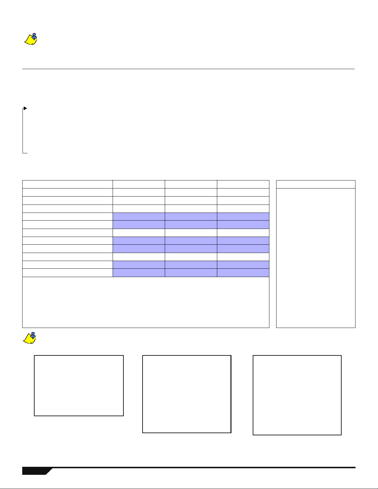
Default Settings:
Options which are bold signify the default value:
e.g. Access code length:
N6 digits 4 digits (4 digit s is th e defaul t value).
More detailed information can be found in the Refe rence & Inst allation Manual, wh ich can be download ed from our website
at paradox.com.
Renamed Products
New Product Codes Previous Product Codes New Product Codes Previous Product Codes
Keypads Door Contacts
K32RF MG32LRF DCT10 MG-DCT10
K32LCD MG32LCD DCTXP2 MG-DCTXP2
K32I MG32I DCT2 MG-DCT2
K32 MG32LED
K10V MG10LEDV Accessories
K10H MG10LEDH 2WPGM MG-2WPGM
Remotes RTX3 MG-RTX3
REM2 / RAC2 MG-REM2 / MG-RAC2 PX8 MG-PX8
REM1 MG-REM1 ZX8SP SP-ZX8
RAC1 MG-RAC1 ZX8 APR-ZX8
Motion Detectors HUB2 APR3-HUB2
PMD1P MG-PMD1P
PMD75 MG-PMD75
PMD85 MG-PMD85
Conventions
Entering Programming Mode
1. Press [
2. Enter your [
3. Enter 3-digit [
4. Enter required [
Magellan / Spectra SP 6
Warning or important information. Suggestion or reminder. Quick Menu (see page 65)
IMPORTANT: StayD Mode must be deactivated in order to enter programming mode. Press [OFF] + [CODE] + [OFF] to
deactivate StayD.
ENTER].
INSTALLER CODE] (default: 000000) or [MAINTENANCE CODE] (no default). [ARM] and [STAY] lights flash.
To modify codes, see System Codes on page 8.
SECTION] you wish to program. [ARM] and [STAY] lights are ON.
DATA].
RPT1 MG-RPT1
PGM4 APR3-PGM4
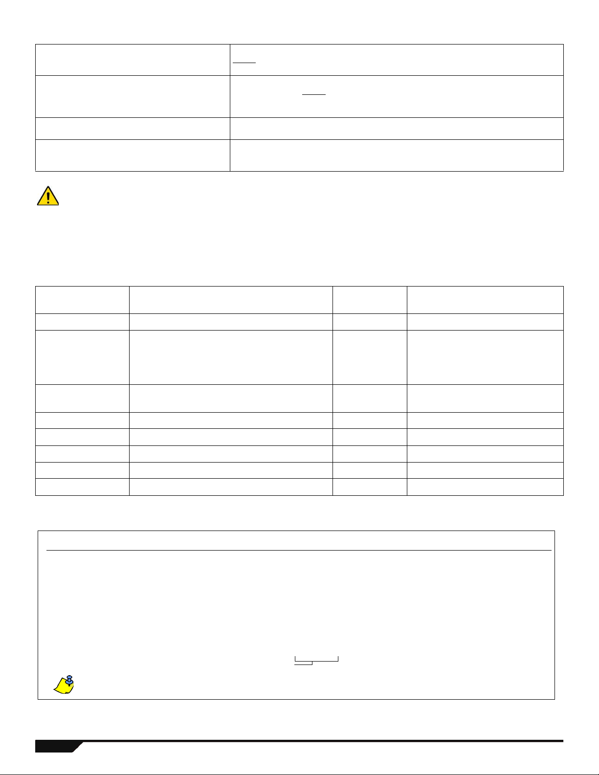
Codes and Panel Reset
Example:
Version 01.42.
Digits 1-4
Step Action Details When Viewing Keypad Version
1 Enter Viewing Mode:
-For panel version, Enter section [980].
-For keypad version, Enter Installer Programming,
then press and hold [
ARM].
The first digit is displayed
(usually “0”)
Digit 1 D [
ARM] is illuminated
2 Press [
ENTER] The second digit is displayed. Digit 2 D [SLEEP] is illuminated
3 Press [
ENTER] The third digit is displayed. Digit 3 D [STAY] is illuminated
4 Press [
ENTER] The fourth digit is displayed. Digit 4 D [OFF] is illuminated
NOTE: K10V/H / K636 keypad version numbers cannot be viewed.
Installer Code (Default: 0000 / 000000)
Maintenance Code (No Default)
System Master Code (Default: 1234 / 123456)
Panel Reset
IMPORTANT: When using an SP Series panel, all wireless sections and options do not apply unless an RTX3 is used in
conjunction with the panel.
IMPORTANT: When using an SP6000 panel in conjunction with an RTX3, all K32 and K10V/H keypads must be versions
2.0 or higher.
IMPORTANT: The K32I Fixed LCD keypad module is only compatible with MG/SP panel version 2.30 and higher.
The Installer code is used to enter programming mode, which allows you to program everything
except
user codes. To change the default code, go to section [397] on page 8 and refer to sec-
tion [701] option [1] on page 23.
The Maintenance code is used to enter programming mode, which allows you to
program everything except
[398], [815], [816], [817], [910], [911], [970], and [975]). To set the default code, go to section
[398] on page 8 and refer to section [701] option [1] on page 23.
The System Master code can use any arming method and can program user codes. To change
the default code, go to section [399] on page 8 and refer to section [701] option [1] on page 23.
Press and hold the RESET switch for five seconds. When the STATUS LED flashes, press the
RESET switch within 2 seconds. However, this will not clear a bus module trouble (see section
[955]). To reset the panel to default using section programming (see section [950]).
for user codes and communication settings (sections [395], [397],
System Overview
Module Description
K32RF, K32IRF 32-Zone Wireless Keypad Modules 8 total Wireless
K10V/H, K32,
K32LCD,
K32I,
10 and 32-Zone Hardwired Keypad Module
K636
ZX8
ZX8SP
8-Zone Expansion Module 3 Min. = 29mA / Max. = 31mA
Maximum num-
ber per system
15 total including
ZX8
and RTX3
K10V/H: Min. = 44mA / Max. = 72mA
K32: Min. = 49mA / Max. = 148mA
K32LCD: Min. = 43mA / Max. = 86mA
K32I: Min. = 30mA / Max. = 70mA
K636: Min. = 28mA / Max. = 33mA
Current
Consumption
RPT1 Magellan Wireless Repeater Module 2 Average = 57mA
VDMP3 Plug-In Voice Dialer 1 Min. = 28mA / Max. = 28mA
IP100 Internet Module 1 Min. = 90mA / Max. = 120mA
RTX3 Wireless Expansion Module (Spectra SP only) 1 Min. = 61mA / Max. = 143mA
PCS100 GSM Communicator Module 1 Min. = 400mA / Max. = 1A
Viewing Version Numbers
7 Programming Guide
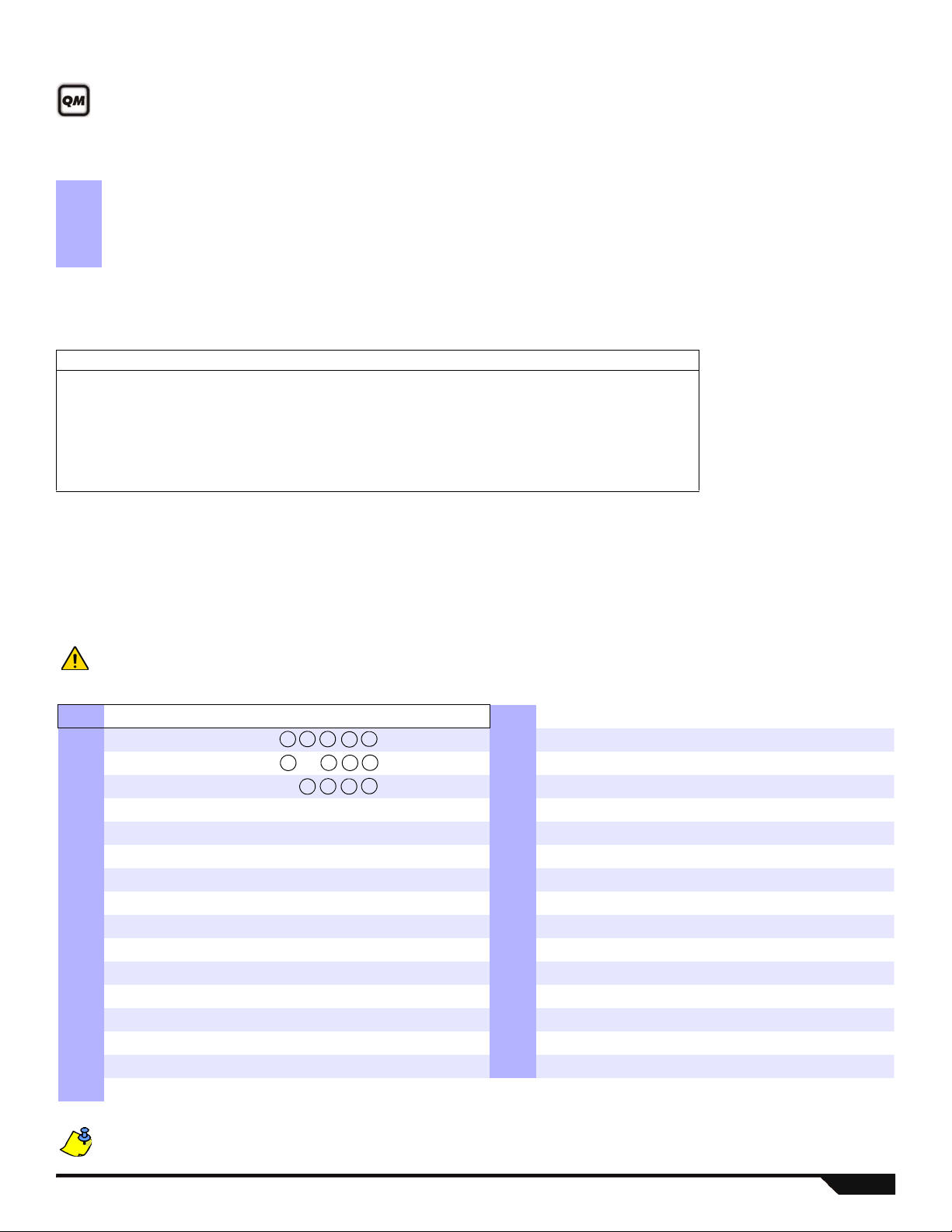
User Programming
Section Options Section Options
[400] Default Option 1 2 3 4 5 6 7 8 [417] User 17: 1 2 3 4 5 6 7 8
[401] System Master: 1 2 3 4 5 6 7 8 [418] User 18: 1 2 3 4 5 6 7 8
[402] Master 1: 1 2 3 4 5 6 7 8 [419] User 19: 1 2 3 4 5 6 7 8
[403] Master 2: 1 2 3 4 5 6 7 8 [420] User 20: 1 2 3 4 5 6 7 8
[404] User 4: 1 2 3 4 5 6 7 8 [421] User 21: 1 2 3 4 5 6 7 8
[405] User 5: 1 2 3 4 5 6 7 8 [422] User 22: 1 2 3 4 5 6 7 8
[406] User 6: 1 2 3 4 5 6 7 8 [423] User 23: 1 2 3 4 5 6 7 8
[407] User 7: 1 2 3 4 5 6 7 8 [424] User 24: 1 2 3 4 5 6 7 8
[408] User 8: 1 2 3 4 5 6 7 8 [425] User 25 1 2 3 4 5 6 7 8
[409] User 9: 1 2 3 4 5 6 7 8 [426] User 26: 1 2 3 4 5 6 7 8
[410] User 10: 1 2 3 4 5 6 7 8 [427] User 27: 1 2 3 4 5 6 7 8
[411] User 11: 1 2 3 4 5 6 7 8 [428] User 28: 1 2 3 4 5 6 7 8
[412] User 12: 1 2 3 4 5 6 7 8 [429] User 29: 1 2 3 4 5 6 7 8
[413] User 13: 1 2 3 4 5 6 7 8 [430] User 30: 1 2 3 4 5 6 7 8
[414] User 14: 1 2 3 4 5 6 7 8 [431] User 31: 1 2 3 4 5 6 7 8
[415] User 15: 1 2 3 4 5 6 7 8 [432] User 32: 1 2 3 4 5 6 7 8
[416] User 16: 1 2 3 4 5 6 7 8
Refer to the Installer Quick Menu on page 65 for installer or maintenance code programming.
Refer to the Master Quick Menu in the User Guide for user code/remote control programming.
System Codes
Section Data Description
[395] ____/____/____(147 to lock, other to unlock) Installer Code Lock (default 000)
[397] ____/____/____/____/____/____ Installer Code (default = 000000)*
[398] ____/____/____/____/____/____ Maintenance Code (no default)
[399] ____/____/____/____/____/____ System Master Code (default = 123456)*
*4 or 6 digits according to section [701] option [1]. The control panel automatically removes the last 2 digits of the user access code if the
length is changed from 6 digits to 4 digits. However, if the user access code length is changed from 4 to 6 digits, the control panel adds 2
digits to the end by using the first two digits.
Maintenance Code Limited Access Table
The Maintenance Code cannot access the following sections:
[395] Installer code lock [817] Backup monitoring station telephone
[397] Installer code [910] Panel ID
[398] Maintenance code [911] PC password
[815] Monitoring station telephone number 1 [970] Download memory key into panel
[816] Monitoring station telephone number 2 [975] Upload panel into the memory key
User Code Options
User Options
1 - Partition 1 Access 5 - Force Arming (Regular/Sleep/StayArming)
2 - Partition 2 Access 6 - Arm Only
3 - Bypass Programming 7 - PGM Activation Only
4 - Stay/Sleep Arming 8 - Duress
When section [400] is accessed, the panel will copy the saved value of that section to all user options- [404] to [432].
Magellan / Spectra SP 8
The System Master, Master 1, and Master 2 user code options cannot be modified. However, if partitioning is not enabled, the user code options for Master 2 will match those of Master 1.

Remote Control Button Assignment
+
+
[SLEEP] - Empty / Button disabled
[1] - Regular / Regular Force arming
[2] - Stay / Stay Force arming
[3] - N/A
[4] - Sleep / Sleep Force arming
[5] - PGM Activation (Event Group 22)*
[6] - PGM Activation (Event Group 23)*
[7] - Activate window mode (StayD)
[8] - Panic 1
[9] - Panic 2
[A] - Panic 3
[B] - PGM Activation (Event Group #8)*
[C] - PGM Activation (Event Group #9)*
[D] - PGM Activation (Event Group #10)*
[E] - PGM Activation (Event Group #11)*
[F] - Paramedic alarm
* See PGM Programming on page 31.
Button Options Table (refer to Decimal and Hexadecimal Values on page 47)
The disarm button ( ) cannot be
modified.
Remote Controls Supported:
REM1 / REM2 / RAC1
RAC2 / REM3
REM1 REM2
RAC1 RAC2
Default data*: 1 B C disabled
* Buttons are programmed using
the Button Options Table below.
REM3 PGM1
[9]
PGM2
[0]
PGM3
[x]
PGM4
[3]
PGM5
[ ]
PGM6
[ ]
PGM3&4
[x] + [3]
PGM5&6
[ ] + [ ]
Default data*: B C D E 5 6 disabled disabled
[610]
All RCs
RC#
______ ______ ______ ______ ______ ______ ______ ______
IMPORTANT: When section [610] is accessed, the panel will copy the saved value of that section to all remotes.
[611] 1 ______ ______ ______ ______ ______ ______ ______ ______
[612] 2 ______ ______ ______ ______ ______ ______ ______ ______
[613] 3 ______ ______ ______ ______ ______ ______ ______ ______
[614] 4 ______ ______ ______ ______ ______ ______ ______ ______
[615] 5 ______ ______ ______ ______ ______ ______ ______ ______
[616] 6 ______ ______ ______ ______ ______ ______ ______ ______
[617] 7 ______ ______ ______ ______ ______ ______ ______ ______
[618] 8 ______ ______ ______ ______ ______ ______ ______ ______
[619] 9 ______ ______ ______ ______ ______ ______ ______ ______
[620] 10 ______ ______ ______ ______ ______ ______ ______ ______
[621] 11 ______ ______ ______ ______ ______ ______ ______ ______
[622] 12 ______ ______ ______ ______ ______ ______ ______ ______
[623] 13 ______ ______ ______ ______ ______ ______ ______ ______
[624] 14 ______ ______ ______ ______ ______ ______ ______ ______
[625] 15 ______ ______ ______ ______ ______ ______ ______ ______
[626] 16 ______ ______ ______ ______ ______ ______ ______ ______
[627] 17 ______ ______ ______ ______ ______ ______ ______ ______
[628] 18 ______ ______ ______ ______ ______ ______ ______ ______
[629] 19 ______ ______ ______ ______ ______ ______ ______ ______
[630] 20 ______ ______ ______ ______ ______ ______ ______ ______
[631] 21 ______ ______ ______ ______ ______ ______ ______ ______
[632] 22 ______ ______ ______ ______ ______ ______ ______ ______
[633] 23 ______ ______ ______ ______ ______ ______ ______ ______
[634] 24 ______ ______ ______ ______ ______ ______ ______ ______
[635] 25 ______ ______ ______ ______ ______ ______ ______ ______
[636] 26 ______ ______ ______ ______ ______ ______ ______ ______
[637] 27 ______ ______ ______ ______ ______ ______ ______ ______
[638] 28 ______ ______ ______ ______ ______ ______ ______ ______
[639] 29 ______ ______ ______ ______ ______ ______ ______ ______
[640] 30 ______ ______ ______ ______ ______ ______ ______ ______
[641] 31 ______ ______ ______ ______ ______ ______ ______ ______
[642] 32 ______ ______ ______ ______ ______ ______ ______ ______
9 Programming Guide
Remote Control (RC) User Assignment
Section Remote Serial Number Section Remote Serial Number
[651] RC 1 for User 1: ____/____/____/____/____/____ [667] RC 17 for User 17: ____/____/____/____/____/____
[652] RC 2 for User 2: ____/____/____/____/____/____ [668] RC 18 for User 18: ____/____/____/____/____/____
[653] RC 3 for User 3: ____/____/____/____/____/____ [669] RC 19 for User 19: ____/____/____/____/____/____
[654] RC 4 for User 4: ____/____/____/____/____/____ [670] RC 20 for User 20: ____/____/____/____/____/____
[655] RC 5 for User 5: ____/____/____/____/____/____ [671] RC 21 for User 21: ____/____/____/____/____/____
[656] RC 6 for User 6: ____/____/____/____/____/____ [672] RC 22 for User 22: ____/____/____/____/____/____
[657] RC 7 for User 7: ____/____/____/____/____/____ [673] RC 23 for User 23: ____/____/____/____/____/____
[658] RC 8 for User 8: ____/____/____/____/____/____ [674] RC 24 for User 24: ____/____/____/____/____/____
[659] RC 9 for User 9: ____/____/____/____/____/____ [675] RC 25 for User 25: ____/____/____/____/____/____
[660] RC 10 for User 10: ____/____/____/____/____/____ [676] RC 26 for User 26: ____/____/____/____/____/____
[661] RC 11 for User 11: ____/____/____/____/____/____ [677] RC 27 for User 27: ____/____/__ __/____/____/____
[662] RC 12 for User 12: ____/____/____/____/____/____ [678] RC 28 for User 28: ____/____/____/____/____/____
[663] RC 13 for User 13: ____/____/____/____/____/____ [679] RC 29 for User 29: ____/____/____/____/____/____
[664] RC 14 for User 14: ____/____/____/____/____/____ [680] RC 30 for User 30: ____/____/____/____/____/____
[665] RC 15 for User 15: ____/____/____/____/____/____ [681] RC 31 for User 31: ____/____/____/____/____/____
[666] RC 16 for User 16: ____/____/____/____/____/____ [682] RC 32 for User 32: ____/____/____/____/____/____
To delete a remote control, enter [000000] in its respective section. To view the serial number of a remote, refer to section [960].
For automatic assignment, press a button on the designated remote while in the respective section.
Refer to the Master Quick Menu in the User Guide for user code/remote control programming.
Magellan / Spectra SP 10

Code Entry for Action Keys (REM3)
The six action keys (PGM1 to PGM6) can be programmed to require a code entry for use.
Section OFF ON
[360] [1] All odd-numbered REM3s N = Code entry for PGM N = One-touch PGM
[2] All odd-numbered REM3s N = Code entry disarm N = One-touch disarm
[3] & [4] N/A N/A
[5] All even-numbered REM3s N = Code entry for PGM N = One-touch PGM
[6] All even-numbered REM3s N = Code entry disarm N = One-touch disarm
[361] [1] REM3 #1 N = Code entry for PGM N = One-touch PGM
[2] REM3 #1 N = Code entry disarm N = One-touch disarm
[3] & [4] N/A N/A
[5] REM3 #2 N = Code entry for PGM N = One-touch PGM
[6] REM3 #2 N = Code entry disarm N = One-touch disarm
[362] [1] REM3 #3 N = Code entry for PGM N = One-touch PGM
[2] REM3 #3 N = Code entry disarm N = One-touch disarm
[3] & [4] N/A N/A
[5] REM3 #4 N = Code entry for PGM N = One-touch PGM
[6] REM3 #4 N = Code entry disarm N = One-touch disarm
[363] [1] REM3 #5 N = Code entry for PGM N = One-touch PGM
[2] REM3 #5 N = Code entry disarm N = One-touch disarm
[3] & [4] N/A N/A
[5] REM3 #6 N = Code entry for PGM N = One-touch PGM
[6] REM3 #6 N = Code entry disarm N = One-touch disarm
[364] [1] REM3 #7 N = Code entry N = One-touch PGM
[2] REM3 #7 N = Code entry disarm N = One-touch disarm
[3] & [4] N/A N/A
[5] REM3 #8 N = Code entry for PGM N = One-touch PGM
[6] REM3 #8 N = Code entry disarm N = One-touch disarm
[365] [1] REM3 #9 N = Code entry for PGM N = One-touch PGM
[2] REM3 #9 N = Code entry disarm N = One-touch disarm
[3] & [4] N/A N/A
[5] REM3 #10 N = Code entry for PGM N = One-touch PGM
[6] REM3 #10 N = Code entry disarm N = One-touch disarm
[366] [1] REM3 #11 N = Code entry for PGM N = One-touch PGM
[2] REM3 #11 N = Code entry disarm N = One-touch disarm
[3] & [4] N/A N/A
[5] REM3 #12 N = Code entry for PGM N = One-touch PGM
[6] REM3 #12 N = Code entry disarm N = One-touch disarm
[367] [1] REM3 #13 N = Code entry for PGM N = One-touch PGM
[2] REM3 #13 N = Code entry disarm N = One-touch disarm
[3] & [4] N/A N/A
[5] REM3 #14 N = Code entry for PGM N = One-touch PGM
[6] REM3 #14 N = Code entry disarm N = One-touch disarm
[368] [1] REM3 #15 N = Code entry for PGM N = One-touch PGM
[2] REM3 #15 N = Code entry disarm N = One-touch disarm
[3] & [4] N/A N/A
[5] REM3 #16 N = Code entry for PGM N = One-touch PGM
[6] REM3 #16 N = Code entry disarm N = One-touch disarm
11 Programming Guide

Section OFF ON
[369] [1] REM3 #17 N = Code entry for PGM N = One-touch PGM
[2] REM3 #17 N = Code entry disarm N = One-touch disarm
[3] & [4] N/A N/A
[5] REM3 #18 N = Code entry for PGM N = One-touch PGM
[6] REM3 #18 N = Code entry disarm N = One-touch disarm
[370] [1] REM3 #19 N = Code entry for PGM N = One-touch PGM
[2] REM3 #19 N = Code entry disarm N = One-touch disarm
[3] & [4] N/A N/A
[5] REM3 #20 N = Code entry for PGM N = One-touch PGM
[6] REM3 #20 N = Code entry disarm N = One-touch disarm
[371] [1] REM3 #21 N = Code entry for PGM N = One-touch PGM
[2] REM3 #21 N = Code entry disarm N = One-touch disarm
[3] & [4] N/A N/A
[5] REM3 #22 N = Code entry for PGM N = One-touch PGM
[6] REM3 #22 N = Code entry disarm N = One-touch disarm
[372] [1] REM3 #23 N = Code entry for PGM N = One-touch PGM
[2] REM3 #23 N = Code entry disarm N = One-touch disarm
[3] & [4] N/A N/A
[5] REM3 #24 N = Code entry for PGM N = One-touch PGM
[6] REM3 #24 N = Code entry disarm N = One-touch disarm
[373] [1] REM3 #25 N = Code entry for PGM N = One-touch PGM
[2] REM3 #25 N = Code entry disarm N = One-touch disarm
[3] & [4] N/A N/A
[5] REM3 #26 N = Code entry for PGM N = One-touch PGM
[6] REM3 #26 N = Code entry disarm N = One-touch disarm
[374] [1] REM3 #27 N = Code entry for PGM N = One-touch PGM
[2] REM3 #27 N = Code entry disarm N = One-touch disarm
[3] & [4] N/A N/A
[5] REM3 #28 N = Code entry for PGM N = One-touch PGM
[6] REM3 #28 N = Code entry disarm N = One-touch disarm
[375] [1] REM3 #29 N = Code entry for PGM N = One-touch PGM
[2] REM3 #29 N = Code entry disarm N = One-touch disarm
[3] & [4] N/A N/A
[5] REM3 #30 N = Code entry for PGM N = One-touch PGM
[6] REM3 #30 N = Code entry disarm N = One-touch disarm
[376] [1] REM3 #31 N = Code entry for PGM N = One-touch PGM
[2] REM3 #31 N = Code entry disarm N = One-touch disarm
[3] & [4] N/A N/A
[5] REM3 #32 N = Code entry for PGM N = One-touch PGM
[6] REM3 #32 N = Code entry disarm N = One-touch disarm
Magellan / Spectra SP 12

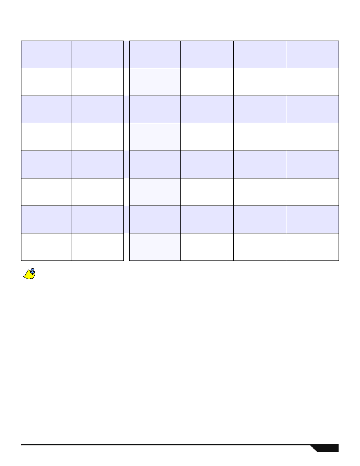
System Planning
IMPORTANT: Maximum of 3 ZX8 modules.
Serial # Sticker Description
Keypad 1 / ZX8
/ ZX8SP
Keypad 2 / ZX8
/ ZX8SP
Keypad 3 / ZX8
/ ZX8SP
Keypad 4 / ZX8
/ ZX8SP
Keypad 5 / ZX8
/ ZX8SP
Keypad 6 / ZX8
/ ZX8SP
Path Zone
(Entry Point)
Path Zone Path Zone Path Zone
Keypad 7 / ZX8
/ ZX8SP
Keypad 8 / ZX8
/ ZX8SP
Keypad 9 / ZX8
/ ZX8SP
Keypad 10 / ZX8
/ ZX8SP
Keypad 11 / ZX8
/ ZX8SP
Keypad 12 / ZX8
/ ZX8SP
Keypad 13 / ZX8
/ ZX8SP
Keypad 14 / ZX8
/ ZX8SP
Keypad 15 / ZX8
/ ZX8SP
13 Programming Guide
Wireless Keypad Planning
Serial # Sticker Description
K32RF / K32IRF 1
K32RF / K32IRF 2
K32RF / K32IRF 3
K32RF / K32IRF 4
K32RF / K32IRF 5
K32RF / K32IRF 6
Path Zone
(Entry Point)
Path Zone Path Zone Path Zone
K32RF / K32IRF 7
K32RF / K32IRF 8
When deleting a wireless keypad (K32RF / K32IRF) from the system, the corresponding StayD path zones will also be deleted.
Magellan / Spectra SP 14
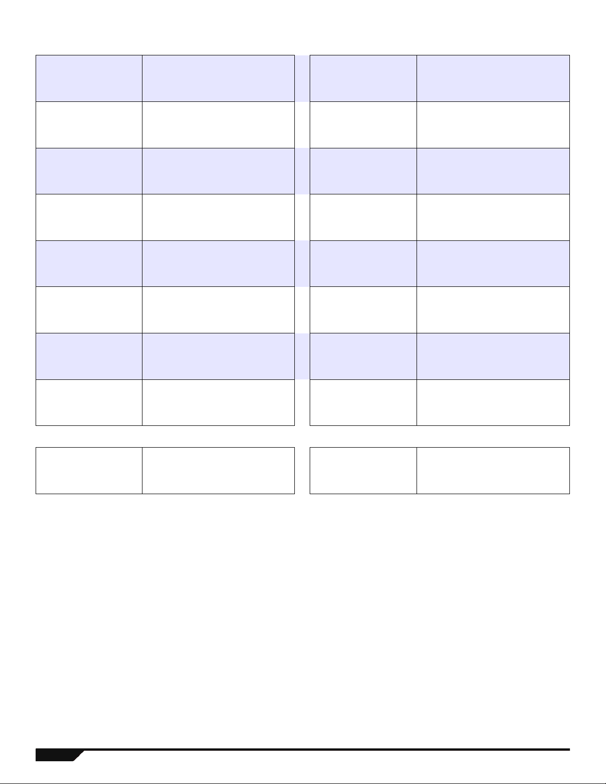
Wireless System Planning
Serial # Sticker Description Serial # Sticker Description
PGM 1 PGM 9
PGM 2 PGM 10
PGM 3 PGM 11
PGM 4 PGM 12
PGM 5 PGM 13
PGM 6 PGM 14
PGM 7 PGM 15
PGM 8 PGM 16
Serial # Sticker Description Serial # Sticker Description
Repeater 1 Repeater 2
15 Programming Guide

Serial # Sticker
Wireless/ZX8 Zone# Zone Description Stay SleepFull Wireless/ZX8 Zone# Zone Description Stay SleepFull
Armed when...
Serial # Sticker
Armed when...
Zone
Zone
Zone
Zone
Zone
Zone
Zone
N N N
NNN
N N N
NNN
N N N
NNN
N N N
Zone
Zone
Zone
Zone
Zone
Zone
Zone
N N N
NNN
N N N
NNN
N N N
NNN
N N N
Zone
Zone
Zone
Zone
Zone
Zone
Zone
NNN
N N N
NNN
N N N
NNN
N N N
NNN
Zone
Zone
Zone
Zone
Zone
Zone
Zone
NNN
N N N
NNN
N N N
NNN
N N N
NNN
Zone
Zone
Magellan / Spectra SP 16
N N N
NNN
Zone
Zone
N N N
NNN
Zone Programming
See Quick Menus on page 65
For keypad zone programming, see page 31.
Zone Recognition (MG Series)
When expanding zones via ZX8, up to 3 ZX8 modules can be added to the system and are identified by the ZX8 3-position jumpers +1,
+9 and +17.
MG5000 No ATZ MG5000 ATZ MG5050 No ATZ MG5050 ATZ
Panel Zone 1: Panel Input 1 Zone 1: Panel Input 1A Zone 1: Panel Input 1 Zone 1: Panel Input 1A
Zone 2: Panel Input 2 Panel Zone 2: Panel Input 2A Zone 2: Panel Input 2 Zone 2: Panel Input 2A
Zone 3: Input 1 Zone 3: Panel Input 1B Panel Zone 3: Panel Input 3 Zone 3: Panel Input 3A
Zone 4: Input 2 Zone 4: Panel Input 2B Zone 4: Panel Input 4 Zone 4: Panel Input 4A
ZX8 Zone 5: Input 3 Zone 5: Input 1 Zone 5: Panel Input 5 Panel Zone 5: Panel Input 5A
Jumper Zone 6: Input 4 Zone 6: Input 2 Zone 6: Input 1 Zone 6: Panel Input 1B
Panel + 1 Zone 7: Input 5 ZX8 Zone 7: Input 3 Zone 7: Input 2 Zone 7: Panel Input 2B
Zone 8: Input 6 Jumper Zone 8: Input 4 ZX8 Zone 8: Input 3 Zone 8: Panel Input 3B
Zone 9: Input 7 Panel + 1 Zone 9: Input 5 Jumper Zone 9: Input 4 Zone 9: Panel Input 4B
Zone 10: Input 8 Zone 10: Input 6 Panel + 1 Zone 10: Input 5 Zone 10: Panel Input 5B
Zone 11: Input 1 Zone 11: Input 7 Zone 11: Input 6 Zone 11: Input 1
Zone 12: Input 2 Zone 12: Input 8 Zone 12: Input 7 Zone 12: Input 2
ZX8 Zone 13: Input 3 Zone 13: Input 1 Zone 13: Input 8 ZX8 Zone 13: Input 3
Jumper Zone 14: Input 4 Zone 14: Input 2 Zone 14: Input 1 Jumper Zone 14: Input 4
Panel + 9 Zone 15: Input 5 ZX8 Zone 15: Input 3 Zone 15: Input 2 Panel + 1 Zone 15: Input 5
Zone 16: Input 6 Jumper Zone 16: Input 4 ZX8 Zone 16: Input 3 Zone 16: Input 6
Zone 17: Input 7 Panel + 9 Zone 17: Input 5 Jumper Zone 17: Input 4 Zone 17: Input 7
Zone 18: Input 8 Zone 18: Input 6 Panel + 9 Zone 18: Input 5 Zone 18: Input 8
Zone 19: Input 1 Zone 19: Input 7 Zone 19: Input 6 Zone 19: Input 1
Zone 20: Input 2 Zone 20: Input 8 Zone 20: Input 7 Zone 20: Input 2
ZX8 Zone 21: Input 3 Zone 21: Input 1 Zone 21: Input 8 ZX8 Zone 21: Input 3
Jumper Zone 22: Input 4 Zone 22: Input 2 Zone 22: Input 1 Jumper Zone 22: Input 4
Panel + 17 Zone 23: Input 5 ZX8 Zone 23: Input 3 Zone 23: Input 2 Panel + 9 Zone 23: Input 5
Zone 24: Input 6 Jumper Zone 24: Input 4 ZX8 Zone 24: Input 3 Zone 24: Input 6
Zone 25: Input 7 Panel + 17 Zone 25: Input 5 Jumper Zone 25: Input 4 Zone 25: Input 7
Zone 26: Input 8 Zone 26: Input 6 Panel + 17 Zone 26: Input 5 Zone 26: Input 8
Zone 27: N/A Zone 27: Input 7 Zone 27: Input 6 Zone 27: Input 1
Zone 28: N/A Zone 28: Input 8 Zone 28: Input 7 ZX8 Zone 28: Input 2
Zone 29: N/A Zone 29: N/A Zone 29: Input 8 Jumper Zone 29: Input 3
Zone 30: N/A Zone 30: N/A Zone 30: N/A Panel + 17 Zone 30: Input 4
Zone 31: N/A Zone 31: N/A Zone 31: N/A Zone 31: Input 5
Zone 32: N/A Zone 32: N/A Zone 32: N/A Zone 32: Input 6
If a zone is already programmed and you assign a device to the same zone, a wireless zone will overwrite a keypad/hardwire
zone, and a keypad zone will overwrite a hardwire zone.
Zone Recognition (SP Series)
When expanding zones via ZX8, up to 3 ZX8 modules can be added to the system and are identified by the ZX8 3-position jumpers +1,
+9 and +17.
SP5500 No ATZ SP5500 ATZ SP6000 No ATZ SP6000 ATZ
Zone 1: Panel Input 1 Zone 1: Panel Input 1A Zone 1: Panel Input 1 Zone 1: Panel Input 1A
Zone 2: Panel Input 2 Zone 2: Panel Input 2A Zone 2: Panel Input 2 Zone 2: Panel Input 2A
Panel Zone 3: Panel Input 3 Zone 3: Panel Input 3A Panel Zone 3: Panel Input 3 Zone 3: Panel Input 3A
Zone 4: Panel Input 4 Zone 4: Panel Input 4A Zone 4: Panel Input 4 Zone 4: Panel Input 4A
Zone 5: Panel Input 5 Panel Zone 5: Panel Input 5A Zone 5: Panel Input 5 Zone 5: Panel Input 5A
Zone 6: Input 1 Zone 6: Panel Input 1B Zone 6: Panel Input 6 Zone 6: Panel Input 6A
Zone 7: Input 2 Zone 7: Panel Input 2B Zone 7: Panel Input 7 Zone 7: Panel Input 7A
ZX8 Zone 8: Input 3 Zone 8: Panel Input 3B ZX8 Zone 8: Panel Input 8 Panel Zone 8: Panel Input 8A
Jumper Zone 9: Input 4 Zone 9: Panel Input 4B Zone 9: Input 1 Zone 9: Panel Input 1B
Panel + 1 Zone 10: Input 5 Zone 10: Panel Input 5B Zone 10: Input 2 Zone 10: Panel Input 2B
Zone 11: Input 6 Zone 11: Input 1 ZX8 Zone 11: Input 3 Zone 11: Panel Input 3B
Zone 12: Input 7 Zone 12:Input 2 Jumper Zone 12: Input 4 Zone 12: Panel Input 4B
17 Programming Guide
SP5500 No ATZ SP5500 ATZ SP6000 No ATZ SP6000 ATZ
Zone 13: Input 8 ZX8 Zone 13: Input 3 Panel + 1 Zone 13: Input 5 Zone 13: Panel Input 5B
Zone 14: Input 1 Jumper Zone 14: Input 4 Zone 14: Input 6 Zone 14: Panel Input 6B
Zone 15: Input 2 Panel + 1 Zone 15: Input 5 Zone 15: Input 7 Zone 15: Panel Input 7B
ZX8 Zone 16: Input 3 Zone 16: Input 6 Zone 16: Input 8 Zone 16: Panel Input 8B
Jumper Zone 17: Input 4 Zone 17: Input 7 Zone 17: Input 1 Zone 17: Input 1
Panel + 9 Zone 18: Input 5 Zone 18: Input 8 Zone 18: Input 2 Zone 18: Input 2
Zone 19: Input 6 Zone 19:Input 1 ZX8 Zone 19: Input 3 ZX8 Zone 19: Input 3
Zone 20: Input 7 Zone 20:Input 2 Jumper Zone 20: Input 4 Jumper Zone 20: Input 4
Zone 21: Input 8 ZX8 Zone 21: Input 3 Panel + 9 Zone 21: Input 5 Panel + 1 Zone 21: Input 5
Zone 22: Input 1 Jumper Zone 22: Input 4 Zone 22: Input 6 Zone 22: Input 6
Zone 23: Input 2 Panel + 9 Zone 23: Input 5 Zone 23: Input 7 Zone 23: Input 7
ZX8 Zone 24: Input 3 Zone 24: Input 6 Zone 24: Input 8 Zone 24: Input 8
Jumper Zone 25: Input 4 Zone 25: Input 7 Zone 25: Input 1 Zone 25: Input 1
Panel + 17 Zone 26: Input 5 Zone 26: Input 8 Zone 26: Input 2 Zone 26: Input 2
Zone 27: Input 6 Zone 27:Input 1 ZX8 Zone 27: Input 3 ZX8 Zone 27: Input 3
Zone 28: Input 7 ZX8 Zone 28: Input 2 Jumper Zone 28: Input 4 Jumper Zone 28: Input 4
Zone 29: Input 8 Jumper Zone 29: Input 3 Panel + 17 Zone 29: Input 5 Panel + 9 Zone 29: Input 5
Zone 30: N/A Panel + 17 Zone 30: Input 4 Zone 30: Input 6 Zone 30: Input 6
Zone 31: N/A Zone 31: Input 5 Zone 31: Input 7 Zone 31: Input 7
Zone 32: N/A Zone 32: Input 6 Zone 32: Input 8 Zone 32: Input 8
If a zone is already programmed and you assign a device to the same zone, a wireless zone will overwrite a keypad/hardwire
zone, and a keypad zone will overwrite a hardwire zone.
SP7000 No ATZ SP7000 ATZ
Zone 1: Panel Input 1 Zone 1: Panel Input 1A
Zone 2: Panel Input 2 Zone 2: Panel Input 2A
Zone 3: Panel Input 3 Zone 3: Panel Input 3A
Zone 4: Panel Input 4 Zone 4: Panel Input 4A
Zone 5: Panel Input 5 Zone 5: Panel Input 5A
Zone 6: Panel Input 6 Zone 6: Panel Input 6A
Zone 7: Panel Input 7 Zone 7: Panel Input 7A
Panel Zone 8: Panel Input 8 Zone 8: Panel Input 8A
Zone 9: Panel Input 9 Zone 9: Panel Input 9A
Zone 10: Panel Input 10 Zone 10: Panel Input 10A
Zone 11: Panel Input 11 Zone 11: Panel Input 11A
Zone 12: Panel Input 12 Zone 12: Panel Input 12A
Zone 13: Panel Input 13 Zone 13: Panel Input 13A
Zone 14: Panel Input 14 Zone 14: Panel Input 14A
Zone 15: Panel Input 15 Zone 15: Panel Input 15A
Zone 16: Panel Input 16 Panel Zone 16: Panel Input 16A
Zone 17: Input 1 Zone 17: Panel Input 1B
Zone 18: Input 2 Zone 18: Panel Input 2B
ZX8 Zone 19: Input 3 Zone 19: Panel Input 3B
Jumper Zone 20: Input 4 Zone 20: Panel Input 4B
Panel + 1 Zone 21: Input 5 Zone 21: Panel Input 5B
Zone 22: Input 6 Zone 22: Panel Input 6B
Zone 23: Input 7 Zone 23: Panel Input 7B
Zone 24: Input 8 Zone 24: Panel Input 8B
Zone 25: Input 1 Zone 25: Panel Input 9B
Zone 26: Input 2 Zone 26: Panel Input 10B
ZX8 Zone 27: Input 3 Zone 27: Panel Input 11B
Jumper Zone 28: Input 4 Zone 28: Panel Input 12B
Panel + 9 Zone 29: Input 5 Zone 29: Panel Input 13B
Zone 30: Input 6 Zone 30: Panel Input 14B
Zone 31: Input 7 Zone 31: Panel Input 15B
Zone 32: Input 8 Zone 32: Panel Input 16B
Magellan / Spectra SP 18
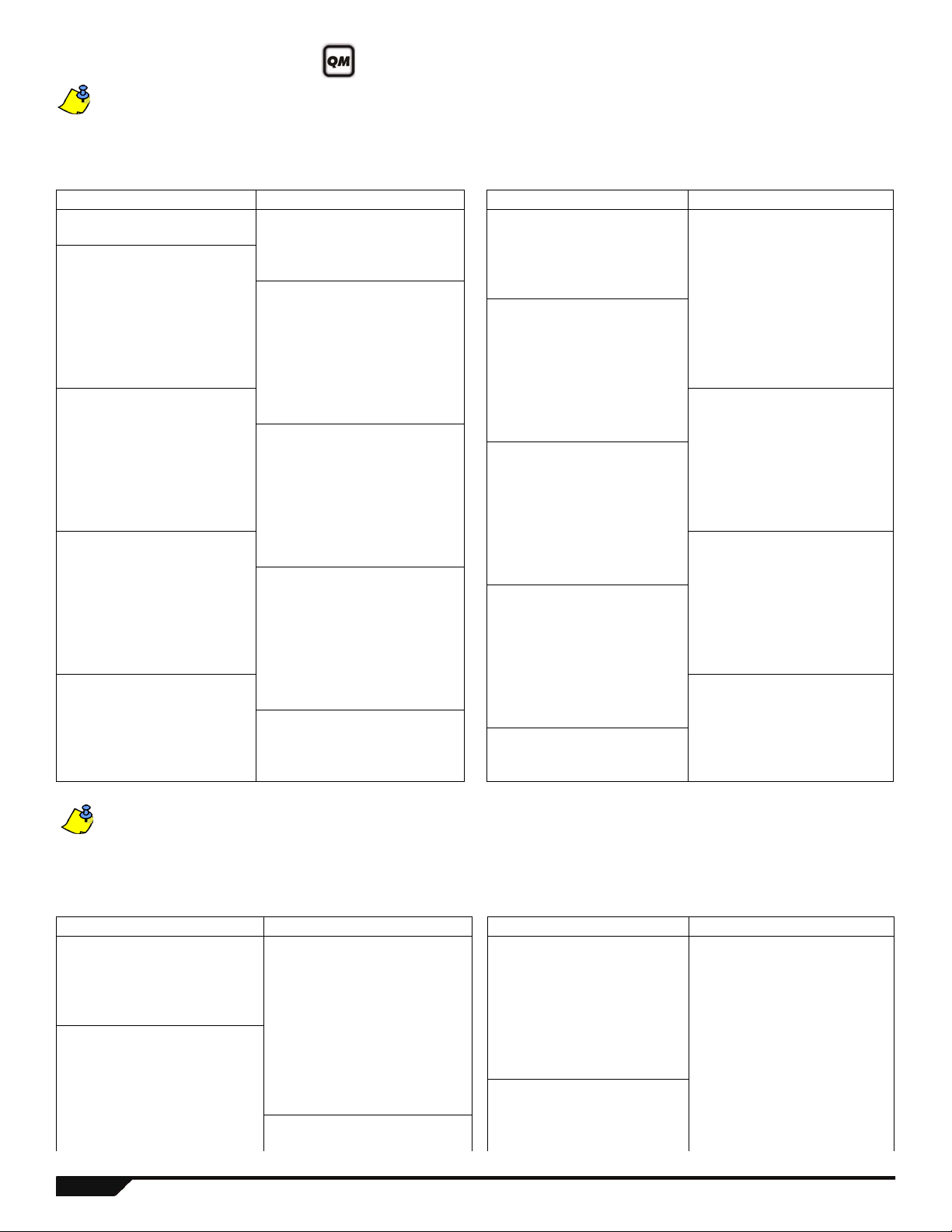
Zone Definitions
[1]- N/A
[2]- N/A
[3]- N/A
[4] OFF = Disarm
ON = Disarm only if Stay/Sleep
armed
[5] = Arm only
[6] = Stay arming‡
[7] = Sleep arming‡
[8] = N/A
‡ Select only one. If all are off, keyswitch will regular arm.
[1] = Auto-zone Shutdown
[2] = Bypassable Zone
[3] =
RF Zone Supervision
[4] [5]
OFF OFF Audible Alarm
OFF ON Pulsed Alarm
ON OFF Silent Alarm
ON ON Report Only
[6] = Intellizone
[7] = Delay alarm transmission
[8] = Force Zone
[1]- Partition 1†
[2]- Partition 2†
[3]- Both partitions†
†
When using a K636 keypad, only
partition 1 is available.
Table 2: Partition Assignment Table 3: Zone Options Table 4: Keyswitch Options
If a zone is already programmed and you assign a device to the same zone, a wireless zone will overwrite a keypad/hardwire
zone, and a keypad zone will overwrite a hardwire zone.
To program zone definitions, zone partitions and assign options:
Step Action Details
1 [
ENTER] + [INSTALLER CODE]
(default: 0000 / 000000)
[ARM] + [STAY] = flash. [MAINTENANCE CODE] may also be used.
2 Enter 3-digit zone you wish to program
[
ARM] + [STAY] = on (see page 20)
[001] to [032]
3 Enter a 2-digit zone definition 2 digits: 01 to 32 (see Table 1 below)
4 Assign Partition
By default, all zones are assigned to partition 1. (see Table 2)
[1], [2] or [3]
5 Select or deselect zone options using
For zone options, see Table 3. For keyswitch options, see Table 4.
buttons [1] to [8]
6 To save and proceed to the next zone,
ENTER]
press [
Table 1: Zone Definitions
Zone Definitions Stay Arm Sleep Arm Fully Arm Zone Definitions
00 = Zone Disabled (default) - - -
11 = Instant Fire†
01 = Entry Delay 1 Entry Delay 1 Entry Delay 1 Entry Delay 1 12 = Delayed Fire†
02 = Entry Delay 2 Entry Delay 2 Entry Delay 2 Entry Delay 2 13 = Instant Fire Silent†
03 = Entry Delay 1 (Full Arm)
Not Armed Not Armed Entry Delay 1 14 = Delayed Fire Silent†
04 = Entry Delay2 (Full Arm) Not Armed Not Armed Entry Delay 2 15 = 24Hr. Buzzer
05 = Follow Follow* Follow* Follow* 16 = 24Hr. Burglary
06 = Follow (Sleep/Full Arm)
Not Armed Follow* Follow 17 = 24Hr . Hold-up
07 = Follow (Full Arm) Not Armed Not Armed Follow 18 = 24Hr. Gas
08 = Instant Instant* Instant* Instant* 19 = 24Hr. Heat
09 = Instant (Sleep/Full Arm)
Not Armed Instant* Instant 20 = 24Hr. Water
10 = Instant (Full Arm) Not Armed Not Armed Instant 21 = 24Hr. Freeze
* Flex-Instant = Zone will follow the delay at section [720], (default is 15 seconds / 0 = instant zone) 22 = 24hr. Panic††
** On-board hardwire control panel zones and ZX8 expansion zones only 23 = Follow No Pre-Alarm
† APR-ZX8 inputs do not support fire zones.
For 2-wire smoke installations (not supported by SP5500), these definitions apply to Zone 1 Input
only. Section [706], option [3] must be enabled.
24 = Instant No Pre-Alarm
25 = Keyswitch Maintain**
26 = Keyswitch Momentary**
For 4-wire smoke installations, use any panel on-board zone input.
†† This alarm will follow the Panic 1 option (section [702], option [1])
For more zone options, see sections [705] and [706] on page 24.
19 Programming Guide

Section Zone*
Zone
Definition
Partition Zone Options
Section
Wireless SN or press tamper/
learn
To delete, enter 000000
[001]
[002]
[003]
[004]
[005]
[006]
[007]
[008]
[009]
[010]
[011]
[012]
[013]
[014]
[015]
[016]
Zone 1: __________________________ _____/_____
Zone 2: __________________________
Zone 3: __________________________
Zone 4: __________________________
Zone 5: __________________________
Zone 6: __________________________
Zone 7: __________________________
Zone 8: __________________________
Zone 9: __________________________
Zone 10: _________________________
Zone 11: _________________________
Zone 12: _________________________
Zone 13: _________________________
Zone 14: _________________________
Zone 15: _________________________
Zone 16: _________________________
_____/_____
_____/_____
_____/_____
_____/_____
_____/_____
_____/_____
_____/_____
_____/_____
_____/_____
_____/_____
_____/_____
_____/_____
_____/_____
_____/_____
_____/_____
_____
_____
_____
_____
_____
_____
_____
_____
_____
_____
_____
_____
_____
_____
_____
_____
12345678
12345678
12345678
12345678
12345678
12345678
12345678
12345678
12345678
12345678
12345678
12345678
12345678
12345678
12345678
12345678
[061] ____/____/____/____/____/____
[062] ____/____/____/____/____/____
[063] ____/____/____/____/____/____
[064] ____/____/____/____/____/____
[065] ____/____/____/____/____/____
[066] ____/____/____/____/____/____
[067] ____/____/____/____/____/____
[068] ____/____/____/____/____/____
[069] ____/____/____/____/____/____
[070] ____/____/____/____/____/____
[071] ____/____/____/____/____/____
[072] ____/____/____/____/____/____
[073] ____/____/____/____/____/____
[074] ____/____/____/____/____/____
[075] ____/____/____/____/____/____
[076] ____/____/____/____/____/____
[017]
[018]
[019]
[020]
[021]
[022]
[023]
[024]
[025]
[026]
[027]
[028]
[029]
[030]
[031]
[032]
Zone 17: _________________________
Zone 18: _________________________
Zone 19: _________________________
Zone 20: _________________________
Zone 21: _________________________
Zone 22: _________________________
Zone 23: _________________________
Zone 24: _________________________
Zone 25: _________________________
Zone 26: _________________________
Zone 27: _________________________
Zone 28: _________________________
Zone 29: _________________________
Zone 30: _________________________
Zone 31: _________________________
Zone 32: _________________________
_____/_____
_____/_____
_____/_____
_____/_____
_____/_____
_____/_____
_____/_____
_____/_____
_____/_____
_____/_____
_____/_____
_____/_____
_____/_____
_____/_____
_____/_____
_____/_____
_____
_____
_____
_____
_____
_____
_____
_____
_____
_____
_____
_____
_____
_____
_____
_____
12345678
12345678
12345678
12345678
12345678
12345678
12345678
12345678
12345678
12345678
12345678
12345678
12345678
12345678
12345678
12345678
[077] ____/____/____/____/____/____
[078] ____/____/____/____/____/____
[079] ____/____/____/____/____/____
[080] ____/____/____/____/____/____
[081] ____/____/____/____/____/____
[082] ____/____/____/____/____/____
[083] ____/____/____/____/____/____
[084] ____/____/____/____/____/____
[085] ____/____/____/____/____/____
[086] ____/____/____/____/____/____
[087] ____/____/____/____/____/____
[088] ____/____/____/____/____/____
[089] ____/____/____/____/____/____
[090] ____/____/____/____/____/____
[091] ____/____/____/____/____/____
[092] ____/____/____/____/____/____
* See Zone Recognition tables on page 17.
Refer to the Installer Quick Menu on page 65.
Magellan / Spectra SP 20
Loading...